EP1502775A1 - Verfahren um der Reifendruck zu schätzen und Fahrzeug ausgestattet mit einem Drucküberwachungsystem, das das Verfahren anwendet - Google Patents
Verfahren um der Reifendruck zu schätzen und Fahrzeug ausgestattet mit einem Drucküberwachungsystem, das das Verfahren anwendet Download PDFInfo
- Publication number
- EP1502775A1 EP1502775A1 EP04291771A EP04291771A EP1502775A1 EP 1502775 A1 EP1502775 A1 EP 1502775A1 EP 04291771 A EP04291771 A EP 04291771A EP 04291771 A EP04291771 A EP 04291771A EP 1502775 A1 EP1502775 A1 EP 1502775A1
- Authority
- EP
- European Patent Office
- Prior art keywords
- wheel
- vertical
- tire
- vertical acceleration
- estimated
- Prior art date
- Legal status (The legal status is an assumption and is not a legal conclusion. Google has not performed a legal analysis and makes no representation as to the accuracy of the status listed.)
- Granted
Links
Images


Classifications
-
- B—PERFORMING OPERATIONS; TRANSPORTING
- B60—VEHICLES IN GENERAL
- B60C—VEHICLE TYRES; TYRE INFLATION; TYRE CHANGING; CONNECTING VALVES TO INFLATABLE ELASTIC BODIES IN GENERAL; DEVICES OR ARRANGEMENTS RELATED TO TYRES
- B60C23/00—Devices for measuring, signalling, controlling, or distributing tyre pressure or temperature, specially adapted for mounting on vehicles; Arrangement of tyre inflating devices on vehicles, e.g. of pumps or of tanks; Tyre cooling arrangements
- B60C23/06—Signalling devices actuated by deformation of the tyre, e.g. tyre mounted deformation sensors or indirect determination of tyre deformation based on wheel speed, wheel-centre to ground distance or inclination of wheel axle
- B60C23/061—Signalling devices actuated by deformation of the tyre, e.g. tyre mounted deformation sensors or indirect determination of tyre deformation based on wheel speed, wheel-centre to ground distance or inclination of wheel axle by monitoring wheel speed
Definitions
- the invention relates generally to the industry automotive and pressure assessment methods motor vehicle tires.
- the invention relates to a first aspect a method of assessing pressure at least one tire mounted on a wheel of a vehicle automobile, this vehicle comprising at least one body, the wheel being connected to the body by a suspension.
- Pressure assessment methods are known from the prior art, in particular by direct measurement, or by indirect measure using the device anti-lock wheels (ABS).
- ABS The indirect method called "ABS” is based on the detection of the variation of the circumference of tire rolling with pressure. It is complex and difficult to develop because many parameters must be taken into account according to the type of tire and type of vehicle, including the vehicle load.
- the present invention aims to to propose another method, not presenting the defects mentioned above.
- the vertical stiffness or the variation of vertical stiffness of the tire is estimated at least from vertical acceleration in the center of the wheel.
- step 1 / comprises a substep of estimating the elevation profile of the ground along the trajectory of the wheel from the acceleration vertical in the center of the wheel.
- the reconciliation of substep 15 / is performed by sampling with a period predetermined the estimate of the second acceleration vertical and the measure of the second acceleration vertical, calculating auto-correlation functions of the estimate of the second vertical acceleration and of measuring the second vertical acceleration on a predetermined sliding duration of observation, and determining for each period the value of the second vertical stiffness that minimizes the difference between the two autocorrelation functions.
- the first step 1 / comprises a sub-step 12 '/ delay between the substeps 12 / and 13 /.
- the estimate of the first stiffness obtained in sub-step 18 / is used in sub-step 12 /, the estimate of the second stiffness vertical obtained in substep 15 / being used in sub-step 16 /.
- the substeps 12 /, 13 /, 16 / and 17 / are performed using a linear model or not two degree of freedom linear modeling the interactions between the soil, the wheel and the body of the vehicle.
- the motor vehicle comprises at minus another wheel, the vertical stiffness of the tire being estimated without using quantities characterizing the behavior of the other wheel (s).
- the vertical stiffness estimated at sub-step 115 / is used in substep 112 /.
- substeps 112 /, 113 /, 114 / and 115 / are performed using a linear model or not two degree of freedom linear modeling the interactions between the soil, the wheel and the body of the vehicle.
- the elevation profile of the soil is estimated also from the vertical acceleration crate of the body, this vertical acceleration cash being measured.
- the altitude profile of the soil is also estimated from the vertical acceleration crate of the crate, this vertical acceleration crate being estimated from the vertical acceleration at center of the wheel.
- the method includes a substep 116 / estimating the vertical acceleration crate to from the vertical acceleration wheel, using predetermined tables and / or mappings characterizing the behavior of the suspension.
- the vertical stiffness of the tire is estimated from the measurement of the wheel relative displacement - body, and / or speed of relative wheel displacement - checkout.
- the pressure or the difference of tire pressure is estimated at step 2 / also in depending on the ambient temperature and / or the speed of the vehicle.
- the invention relates to a motor vehicle comprising at least one tire, a device for monitoring the pressure of said suitable tire to implement the pressure assessment method described above, warning means of the conductor activated by the monitoring device when the tire pressure comes out of a fork predetermined and / or pressure display means of the tire.
- the vehicle comprises a device driving of at least one vehicle member, such as the suspension or braking device, this device controlling said member according to the estimated pressure by the monitoring device.
- the vehicle comprises a sensor angle of the steering wheel, the monitoring device of the pressure is inhibited when the steering wheel angle predetermined range.
- the vehicle includes a sensor acceleration, the monitoring device of the pressure is inhibited when the acceleration comes out of a predetermined range.
- the method of the invention is based on modeling of the interactions between the C box of the vehicle, its wheels R related to the body C, and the ground.
- a two-degree of freedom model is used, in which the body C is likened to a mass Mc suspended from the wheel R o of mass Mr by a suspension assimilated to a spring / damper assembly, this assembly characterized by a stiffness Kc and a damping coefficient R.
- the wheel R o and the body C move in a vertical direction and occupy respective altitudes Zr and Zc with respect to a reference level.
- This reference level may for example be the altitude of the ground at the start of the vehicle.
- the wheel R o carries a tire Pn resting on the ground, assimilated to a spring of vertical stiffness Kp.
- the behavior of the system is controlled by the evolution in time of the altitude Zs of the soil by report to that reference level, that is to say by the profile of the ground covered by the wheel.
- the invention is based on the observation that stiffness vertical Kp of the tire is a signature of the pressure P of the tire.
- the vertical stiffness Kp of the tire is mainly estimated from the vertical acceleration Ar in the center of the wheel R o .
- This acceleration is measured directly by a dedicated sensor, or is estimated from another measurement, for example a measurement of the vertical force exerted in the center of the wheel R o .
- maps and tabulations to determine the pressure P of the tire can be parameterized according to the ambient temperature T and / or vehicle speed V. These parameters are measured by other sensors. These maps and tabulations are determined by calculation in according to the characteristics of the vehicle and validated experimentally.
- the first embodiment makes it possible to determine this stiffness from measurements made on the wheel, possibly supplemented by measurements made on the box. It does not use measurements made on the other wheels of the vehicle.
- the second embodiment makes it possible to determine together the vertical stiffness Kp of the two wheels placed on the same side of the vehicle, using measurements made on both wheels.
- the third embodiment makes it possible to detect a relative variation of the stiffnesses of the two wheels arranged on the same side of the vehicle with respect to the other, using measurements made on both wheels.
- accelerations in the center wheel are noted Ar when they are measured directly, and ⁇ r when they are estimated by calculation. It is the same for the acceleration cash measured Ac and estimated ⁇ c.
- the vertical stiffness Kp estimated at the substep 115 / is used as input for iteration following in sub-step 112 /.
- Substeps 112 /, 113 /, 114 /, 115 / and 116 / are performed in a first variant embodiment using a non-linear calculation model or, in a second variant embodiment, using a model of linear calculation.
- the first variant corresponds to FIGS. 3E.
- the suspension effort Fc is then determined at from the relative speed of travel Vre1 using tables, or possibly maps, predetermined characteristics characterizing the behavior of the suspension. This effort is the sum of two terms: the spring force Fk and the damping force Fr.
- the damping force Fr is read in a table supplied by the manufacturer of the shock absorber, from the relative speed of travel Vrel.
- the spring force Fk is read in a table supplied by the manufacturer of the shock absorber, from Zrel wheel-to-wheel relative travel. For this purpose, determines this travel by integrating the speed of relative movement Vrel.
- the cash acceleration ⁇ c is determined simply by division of the suspension force Fc by the mass of the Mc case.
- the vertical speed of the Vc box used previously to determine the speed of travel relative Vrel is obtained by integration of the acceleration caissec obtained at the iteration previous.
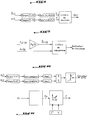
- Step 112 / is shown in Figure 3B.
- the vertical acceleration Ar at the wheel center measured in substep 111 / is first multiplied by the weight of the wheel Mr. It is also estimated the effort suspension Fc from the vertical acceleration of the box ⁇ c estimated at sub-step 116 / by multiplying this one by the mass of the box Mc. We add up then these two terms and divide the sum by the vertical stiffness of the Kp tire supplied to the sub-step 115 /. Add the resulting result to the altitude Zr wheel provided by the sub-step 113 / to determine the altitude of the ground Zs.
- the vertical acceleration Ar at the center measured wheel sub-step 111 / is integrated twice to obtain the wheel altitude Zr.
- the vertical force of the tire obtained at sub-step 114 / is divided by the vertical stiffness of the Kp tire provided in the substep 115, the result being added to the wheel altitude Zr to estimate the altitude soil Zs.
- Figure 3C illustrates substep 114 /.
- the second embodiment variant corresponding the linear calculation model, is represented on the Figures 4A and 4B.
- FIG. 4A represents the substep 116 / which aims to determine the vertical acceleration ⁇ c of the body from the equations:
- C (p) H 4 (p) x Ar (p)
- H 4 (p) (R xp / Kc + 1) / (Mc xp 2 / Kc + R xp / Kc +1)
- FIG. 4B represents the substep 112 /, which aims to estimate the altitude of the ground Zs under the wheel from the following equations:
- Zs (p) Ar / (H'1 (p) x Kp)
- H'1 (p) (Mcp 4 + Rp 3 + Kcp 2 ) / (MrMcp 4 + R (Mc + Mr) p 3 + MrKc + Mc (Kc + Kp) p 2 + RKpp + KcKp)
- Ar is measured in substep 111 /.
- Substeps 114 / and 115 / are performed from same way as in the first embodiment variant, using the same equations.
- the acceleration vertical fund Ac is measured directly using a sensor fitted to the vehicle.
- the substep 116 / described above is therefore replaced by a simple measurement step.
- the value measured is then used in substeps 112 / and 114 /.
- FIG. 5 A second embodiment of the invention is illustrated in Figures 5 to 9.
- These wheels are typically respectively the wheels front and rear of the same side of the motor vehicle.
- the estimate of the first vertical stiffness Kp1 obtained in substep 18 / is used in the substep 12 /, and the estimate of the second vertical stiffness Kp2 obtained in substep 15 / is used in the substep 16 /.
- substeps 12 /, 13 /, 16 /, and 17 / are performed in a first variant embodiment using a non-linear calculation model or, in a second variant embodiment, using a model of linear calculation.
- the damping force Fr is read in a table supplied by the manufacturer of the shock absorber, from the relative speed of travel Vrel1.
- the spring force Fk is read in a table supplied by the manufacturer of the shock absorber, from relative travel first Zrel1 wheel. In this effect, this deflection is determined by integrating the relative speed of travel Vrel1.
- the cash acceleration ⁇ c is determined simply by division of the first suspension effort Fc1 by the body mass Mc.
- the vertical speed of the Vc box used previously to determine the speed of travel relative Vrel1 is obtained by integration of the cash acceleration ⁇ c obtained previously.
- the altitude of the first wheel Zr1 is estimated by integrating the vertical speed Vr1 of the first wheel R1 determined previously.
- the vertical acceleration Ar1 in the center of the first wheel R1 measured in sub-step 11 / is multiplied by the mass Mr1 of the first wheel R1 and added to the acceleration of the fund ⁇ c estimated more high, itself multiplied by the mass of the body Mc.
- the result obtained is divided by the first stiffness Kp1 vertical of the first tire Pn1 estimated at the substep 18 /. Add the resulting result to the altitude Zr1 of the first wheel R1 previously determined for get the ground altitude Zs1 under the first wheel R1.
- the altitude Zr2 is estimated at the center of the second wheel by integrating twice the second vertical acceleration ⁇ r2 estimated previously.
- the reconciliation of sub-step 15 / is performed according to the algorithm of Figure 8, in sampling with a predetermined period T the estimate of the second vertical acceleration ⁇ r2 and the measurement of the second vertical acceleration Ar2, in placing these values in a buffer, calculating the autocorrelation functions, respectively X and X ', of the estimate of the second vertical acceleration ⁇ r2 and the measurement of the second vertical acceleration Ar2 over a predetermined sliding observation period D, and by determining for each period the value of the second vertical stiffness Kp2 which minimizes the difference between the two auto-correlation functions X and X '.
- the observation duration D is typically chosen equal to M x T, with M integer.
- the decision criterion for determining the second vertical stiffness Kp2 is to minimize the gap between the two curves formed by the values successive self-correlations X and X ', for example at meaning of least squares.
- This property makes it possible to assimilate the altitude of the ground Zs2 under second wheel R2 at ground altitude Zs1 under the first wheel R1 to perform the substep 13 /, since the two wheels are arranged one behind the other.
- the second wheel, arranged behind the first "Will see” the same soil profile as the first wheel, with a lag in the constant time.
- Substeps 16 /, 17 / and 18 / are similar to sub-steps 12 /, 13 / and 15 / and will not be described right here.
- the linear model corresponds to FIGS. 7A and 7B.
- the sub-step 13 / is performed simply by inverting the first equation used in the substep 12 /:
- Sub-step 15 / is similar to that of first variant embodiment and will not be described in detail.
- the substeps 16 / to 18 / are similar to substeps 12 /, 13 / and 15 /.
- substeps 12 / and 16 / are executed not with the values respectively second and first stiffness verticals Kp2 and Kp1 estimated at substeps 18 / and 15 /, but with predetermined constant values.
- This variant makes it possible to simplify the algorithm of calculation by avoiding loopbacks.
- step 1 / may include a substep 12 '/ delay between sub-steps 12 / and 13 /. This delay corresponds to the time difference with which the soil profile "seen" by the first wheel arrives under the second wheel, located behind the first.
- the acceleration vertical case Ac is measured directly using a sensor fitted to the vehicle.
- Substeps 12 / and 16 / described above can then be considerably simplified in the first variant embodiment corresponding to the nonlinear model.
- the This method only includes substeps 11 / to 15 /, sub-steps 16 / to 18 / being excluded. Only the second vertical stiffness 12 can be determined in this case.
- the measurement of the acceleration vertical fund Ac can also be exploited to test the robustness calculations made and confirm the estimates of the first and second vertical stiffness Kp1 and Kp2 obtained.
- Figure 9 shows an example of use of the measurement of the acceleration vertical fund Ac in this purpose, in the context of the second variant of corresponding to the linear model.
- This use can be transposed by the man of the craft to the first embodiment variant, corresponding to the nonlinear model.
- reconciliation sub-steps 15 / and 18 / can be implemented in replacing the calculation of the autocorrelation function vertical accelerations at the wheel center measured (Ar1, Ar2) and estimated (Ar1, Ar2) by calculating a other function, such as covariance, spectral density of power or the Fourier transform.
- the third embodiment of the invention is shown in Figure 10. It aims to detect a relative drift of the respective pressures of the first and second tires relative to each other.
- the first and second tires are, for example, the tires respectively front and rear on the same side of the vehicle.
- the measures in substeps 211 / and 213 / are carried out with a predetermined period T.
- the values measured values are stored in a buffer.
- the first and second functions are the autocorrelation functions X and X 'respectively first and second vertical accelerations Ar1 and Ar2, calculated for a sliding duration equal to M x T, with M whole. These functions are defined above.
- Zs1 (p) Ar1 (p) / (H'11 (p) x Kp1)
- Zs2 (p) Ar2 (p) / (H'12 (p) x Kp2)
- the relative difference in stiffness is then determined verticals Kp1 and Kp2 of the first and second tires Pn1 and Pn2 relative to each other according to the ratio Y to using a predetermined map.
- This mapping is established by simulation, considering that the first and second tires are normally reference pressures, for example 2.0 bars in front and 2.3 bars at the back.
- the cartography is then validated experimentally. This gives an indicator of Kp.
- this relative difference in stiffness vertical is translated into pressure difference, using the maps described in the first mode of realization.
- This third embodiment therefore makes it possible to detect that the pressure of a vehicle tire has varied and identify which side of the vehicle is the tire. It does not identify the tire in question, nor does it identify determine if this tire is the front tire or the tire back.
- the autocorrelation function can be replaced by the variance for calculating stiffness vertical tires.
- the third embodiment is then applied of the method to each of the two sides of the vehicle, and performs, in addition, a comparison between the X functions front wheels, and a comparison between X function of the two rear wheels.
- the third mode of embodiment of the invention could detect if, on one side of the vehicle, the pressure of one of the two tires relative to the other had varied.
- the side is identified, it is determined whether the X-functions of the two front tires evolved the same way. If a difference is detected, the tire whose pressure has varied is the front tire of the offending side. Yes no difference is detected, we compare the X functions of the two rear tires. If we detect a difference, the tire whose pressure has varied is the tire back of the offending side.
- the pressure evaluation method is intended to be applied to a motor vehicle comprising four tires, a device for monitoring the tire pressure suitable for implementing the method described above, and the means driver warning enabled by the device when the pressure of a tire comes out a predetermined range.
- the warning means may be audible or visuals.
- this device pilot said organ according to the pressure, or the pressure variation, estimated by the monitoring.
- the vehicle preferably comprises a steering wheel angle sensor, the monitoring device pressure being inhibited when the steering wheel angle a predetermined range.
- the vehicle preferably comprises a acceleration sensor measuring acceleration longitudinal and transverse direction of the vehicle, the device pressure monitoring being inhibited when the acceleration comes out of a predetermined range.
- step 2 the maps used in step 2 / are not valid for strong accelerations transversal, nor for strong accelerations longitudinal.
- the calculation algorithms previously described can be adapted so that the Measured magnitude is not the vertical acceleration Ar in the center wheel but rather the relative movement wheel-case Zrel, or the speed of relative deflection Vrel cash wheel.
- the method of the invention is particularly advantageous since it allows monitor the tire pressure in a simple way and economic.
- the necessary instrumentation is limited to one simple vertical acceleration sensor at the wheel center.
Applications Claiming Priority (2)
| Application Number | Priority Date | Filing Date | Title |
|---|---|---|---|
| FR0309448 | 2003-07-31 | ||
| FR0309448A FR2858267B1 (fr) | 2003-07-31 | 2003-07-31 | Methode d'evaluation de la pression des pneumatiques, et vehicule automobile equipe d'un dispositif de serveillance de la pression apte a la mettre en oeuvre. |
Publications (2)
| Publication Number | Publication Date |
|---|---|
| EP1502775A1 true EP1502775A1 (de) | 2005-02-02 |
| EP1502775B1 EP1502775B1 (de) | 2009-09-23 |
Family
ID=33523034
Family Applications (1)
| Application Number | Title | Priority Date | Filing Date |
|---|---|---|---|
| EP04291771A Not-in-force EP1502775B1 (de) | 2003-07-31 | 2004-07-12 | Verfahren zum Abschätzen des Reifendrucks und Fahrzeug ausgestattet mit einem Drucküberwachungsystem, das dieses Verfahren anwendet |
Country Status (4)
| Country | Link |
|---|---|
| EP (1) | EP1502775B1 (de) |
| AT (1) | ATE443620T1 (de) |
| DE (1) | DE602004023258D1 (de) |
| FR (1) | FR2858267B1 (de) |
Cited By (4)
| Publication number | Priority date | Publication date | Assignee | Title |
|---|---|---|---|---|
| WO2007031678A2 (fr) * | 2005-09-16 | 2007-03-22 | Peugeot Citroen Automobiles Sa | Procede et systeme de diagnostic de l'etat de pneumatiques d'un vehicule automobile |
| WO2007031677A2 (fr) * | 2005-09-16 | 2007-03-22 | Peugeot Citroen Automobiles Sa | Procede et systeme de determination de l'etat d'au moins un pneumatique d'une roue de vehicule |
| WO2007031675A1 (fr) * | 2005-09-16 | 2007-03-22 | Peugeot Citroen Automobiles Sa | Dispositif et procede de mesure d'une quantite representative de la vitesse de rotation d'une roue de vehicule automobile et systeme et procede utilisant un tel dispositif et un tel procede |
| US8825267B2 (en) | 2007-03-16 | 2014-09-02 | Nira Dynamics Ab | Use of suspension information in tire pressure deviation detection for a vehicle tire |
Families Citing this family (2)
| Publication number | Priority date | Publication date | Assignee | Title |
|---|---|---|---|---|
| FR2889111B1 (fr) * | 2005-07-26 | 2007-10-19 | Peugeot Citroen Automobiles Sa | Systeme de determination de la pression de gonflage de pneumatiques montes sur des roues avant et arriere d'un vehicule automobile |
| FR2889112B1 (fr) * | 2005-07-26 | 2007-10-19 | Peugeot Citroen Automobiles Sa | Systeme de determination de la pression de gonflage de pneumatiques montes sur des roues de vehicule automobile |
Citations (5)
| Publication number | Priority date | Publication date | Assignee | Title |
|---|---|---|---|---|
| DE2905931A1 (de) * | 1979-02-16 | 1980-08-28 | Daimler Benz Ag | Vorrichtung zur ueberwachung von stossdaempfern und reifenluftdruck von fahrzeugraedern |
| DE3937403A1 (de) * | 1989-11-10 | 1991-05-16 | Porsche Ag | Verfahren und einrichtung zur ueberwachung der funktionstuechtigkeit eines fahrwerks fuer ein kraftfahrzeug |
| US5412584A (en) * | 1992-11-30 | 1995-05-02 | Kabushiki Kaisha Toyota Chuo Kenkyusho | Dynamic system diagnosing apparatus, tire air pressure diagnosing apparatus and vehicle body weight change detecting apparatus using same |
| DE19723037A1 (de) * | 1996-06-07 | 1997-12-18 | Volkswagen Ag | Reifendruck-Überwachungssystem |
| US6060984A (en) * | 1998-01-29 | 2000-05-09 | Daimlerchrysler Ag | System for monitoring the inflation pressure of a vehicle |
-
2003
- 2003-07-31 FR FR0309448A patent/FR2858267B1/fr not_active Expired - Fee Related
-
2004
- 2004-07-12 DE DE602004023258T patent/DE602004023258D1/de active Active
- 2004-07-12 AT AT04291771T patent/ATE443620T1/de not_active IP Right Cessation
- 2004-07-12 EP EP04291771A patent/EP1502775B1/de not_active Not-in-force
Patent Citations (5)
| Publication number | Priority date | Publication date | Assignee | Title |
|---|---|---|---|---|
| DE2905931A1 (de) * | 1979-02-16 | 1980-08-28 | Daimler Benz Ag | Vorrichtung zur ueberwachung von stossdaempfern und reifenluftdruck von fahrzeugraedern |
| DE3937403A1 (de) * | 1989-11-10 | 1991-05-16 | Porsche Ag | Verfahren und einrichtung zur ueberwachung der funktionstuechtigkeit eines fahrwerks fuer ein kraftfahrzeug |
| US5412584A (en) * | 1992-11-30 | 1995-05-02 | Kabushiki Kaisha Toyota Chuo Kenkyusho | Dynamic system diagnosing apparatus, tire air pressure diagnosing apparatus and vehicle body weight change detecting apparatus using same |
| DE19723037A1 (de) * | 1996-06-07 | 1997-12-18 | Volkswagen Ag | Reifendruck-Überwachungssystem |
| US6060984A (en) * | 1998-01-29 | 2000-05-09 | Daimlerchrysler Ag | System for monitoring the inflation pressure of a vehicle |
Cited By (9)
| Publication number | Priority date | Publication date | Assignee | Title |
|---|---|---|---|---|
| WO2007031678A2 (fr) * | 2005-09-16 | 2007-03-22 | Peugeot Citroen Automobiles Sa | Procede et systeme de diagnostic de l'etat de pneumatiques d'un vehicule automobile |
| WO2007031677A2 (fr) * | 2005-09-16 | 2007-03-22 | Peugeot Citroen Automobiles Sa | Procede et systeme de determination de l'etat d'au moins un pneumatique d'une roue de vehicule |
| WO2007031675A1 (fr) * | 2005-09-16 | 2007-03-22 | Peugeot Citroen Automobiles Sa | Dispositif et procede de mesure d'une quantite representative de la vitesse de rotation d'une roue de vehicule automobile et systeme et procede utilisant un tel dispositif et un tel procede |
| FR2890899A1 (fr) * | 2005-09-16 | 2007-03-23 | Peugeot Citroen Automobiles Sa | Procede et systeme de determination de l'etat d'au moins un pneumatique d'une roue de vehicule. |
| FR2890898A1 (fr) * | 2005-09-16 | 2007-03-23 | Peugeot Citroen Automobiles Sa | Procede et systeme de diagnostic de l'etat de pneumatiques d'un vehicule automobile. |
| FR2891055A1 (fr) * | 2005-09-16 | 2007-03-23 | Peugeot Citroen Automobiles Sa | Dispositif et procede de mesure d'une quantite representative de la vitesse de rotation d'une roue de vehicule automobile et systeme et procede utilisant un tel dispositif et un tel procede. |
| WO2007031678A3 (fr) * | 2005-09-16 | 2007-05-03 | Peugeot Citroen Automobiles Sa | Procede et systeme de diagnostic de l'etat de pneumatiques d'un vehicule automobile |
| WO2007031677A3 (fr) * | 2005-09-16 | 2007-05-03 | Peugeot Citroen Automobiles Sa | Procede et systeme de determination de l'etat d'au moins un pneumatique d'une roue de vehicule |
| US8825267B2 (en) | 2007-03-16 | 2014-09-02 | Nira Dynamics Ab | Use of suspension information in tire pressure deviation detection for a vehicle tire |
Also Published As
| Publication number | Publication date |
|---|---|
| EP1502775B1 (de) | 2009-09-23 |
| FR2858267B1 (fr) | 2006-03-03 |
| FR2858267A1 (fr) | 2005-02-04 |
| ATE443620T1 (de) | 2009-10-15 |
| DE602004023258D1 (de) | 2009-11-05 |
Similar Documents
| Publication | Publication Date | Title |
|---|---|---|
| EP3083360A1 (de) | Schätzung des haftpotenzials durch beurteilung des rollradius | |
| EP1417465B1 (de) | Verfahren zur bestimmung der eigenschaften eines reifens aus belastungen | |
| EP2758257B1 (de) | Verfahren zur schätzung des rollwiderstandes eines fahrzeugrades | |
| FR3042281A1 (fr) | Procede de determination de l'acceleration radiale de la roue d'un vehicule | |
| WO2003045718A1 (fr) | Procede pour evaluer la frequence instantanee d'une excitation mecanique exercee sur une roue d'un vehicule automobile, et applications | |
| EP1502775B1 (de) | Verfahren zum Abschätzen des Reifendrucks und Fahrzeug ausgestattet mit einem Drucküberwachungsystem, das dieses Verfahren anwendet | |
| EP3010746B1 (de) | System und verfahren zur überwachung des durch den motor eines elektro- oder hybridmotorfahrzeugs erzeugten drehmoments | |
| FR2809488A1 (fr) | Methode de determination de composantes d'efforts subis par un pneumatique | |
| FR2973115A1 (fr) | Estimation du rayon dynamique d'une roue et de la vitesse d'un vehicule automobile | |
| FR2889111A1 (fr) | Systeme de determination de la pression de gonflage de pneumatiques montes sur des roues avant et arriere d'un vehicule automobile | |
| EP2937232B1 (de) | Verfahren und vorrichtung zur bestimmung der radlast, mit einer solchen vorrichtung ausgestattetes rad und verfahren und system zur charakterisierung eines fahrzeugs | |
| FR3065075A1 (fr) | Dispositif pour la verification des pneumatiques | |
| WO2007012772A2 (fr) | Systeme de determination de la pression de gonflage de pneumatiques montes sur des roues de vehicule automobile | |
| EP2157002B1 (de) | Verfahren zur Bestimmung des Schwimmwinkels eines Kraftfahrzeugs | |
| FR2935807A1 (fr) | Procede de detection de l'arret d'un vehicule automobile | |
| FR2912363A1 (fr) | Systeme et procede de determination de l'angle de devers d'un vehicule a partir des efforts exerces sur les roues | |
| FR2922014A3 (fr) | Systeme de determination de position de centre de gravite d'un vehicule automobile. | |
| EP1612062A2 (de) | Methode zur Bestimmung einer Druckabweichung eines Fahrzeugreifens | |
| EP3080565B1 (de) | Vorrichtung und verfahren zur schätzung der gesamtmasse eines kraftfahrzeugs mit fahrzeuginterner kalibrierung von aufhängungsverlagerungssensoren | |
| FR3043466A1 (fr) | Procede de determination de l'erreur de mesure de l'acceleration radiale d'une roue et de correction dynamique de cette mesure | |
| EP2830895B1 (de) | Verfahren zur abschätzung des rollwiderstandes eines kraftfahrzeugsrads | |
| EP1612061A1 (de) | Verfahren zum Detektieren des Druckverlustes zumindest eines Fahrzeugsreifens | |
| EP3835716A1 (de) | Verfahren zur kontrolle der radverformung, entsprechende vorrichung und entsprechendes system, das diese vorrichtung umfasst | |
| FR2890737A1 (fr) | Dispositif d'estimation du deplacement d'un groupe moteur par rapport a la struture d'un vehicule automobile et systeme d'evaluation du couple transmis par le groupe moteur | |
| EP3068635B1 (de) | Auf fuzzy-logik basierendes entscheidungsunterstützungsverfahren zur überwachung eines kraftfahrzeugreifendrucks |
Legal Events
| Date | Code | Title | Description |
|---|---|---|---|
| PUAI | Public reference made under article 153(3) epc to a published international application that has entered the european phase |
Free format text: ORIGINAL CODE: 0009012 |
|
| AK | Designated contracting states |
Kind code of ref document: A1 Designated state(s): AT BE BG CH CY CZ DE DK EE ES FI FR GB GR HU IE IT LI LU MC NL PL PT RO SE SI SK TR |
|
| AX | Request for extension of the european patent |
Extension state: AL HR LT LV MK |
|
| 17P | Request for examination filed |
Effective date: 20050720 |
|
| AKX | Designation fees paid |
Designated state(s): AT BE BG CH CY CZ DE DK EE ES FI FR GB GR HU IE IT LI LU MC NL PL PT RO SE SI SK TR |
|
| 17Q | First examination report despatched |
Effective date: 20070711 |
|
| GRAP | Despatch of communication of intention to grant a patent |
Free format text: ORIGINAL CODE: EPIDOSNIGR1 |
|
| GRAS | Grant fee paid |
Free format text: ORIGINAL CODE: EPIDOSNIGR3 |
|
| GRAA | (expected) grant |
Free format text: ORIGINAL CODE: 0009210 |
|
| AK | Designated contracting states |
Kind code of ref document: B1 Designated state(s): AT BE BG CH CY CZ DE DK EE ES FI FR GB GR HU IE IT LI LU MC NL PL PT RO SE SI SK TR |
|
| REG | Reference to a national code |
Ref country code: GB Ref legal event code: FG4D Free format text: NOT ENGLISH |
|
| REG | Reference to a national code |
Ref country code: CH Ref legal event code: EP |
|
| REG | Reference to a national code |
Ref country code: IE Ref legal event code: FG4D |
|
| REF | Corresponds to: |
Ref document number: 602004023258 Country of ref document: DE Date of ref document: 20091105 Kind code of ref document: P |
|
| PG25 | Lapsed in a contracting state [announced via postgrant information from national office to epo] |
Ref country code: FI Free format text: LAPSE BECAUSE OF FAILURE TO SUBMIT A TRANSLATION OF THE DESCRIPTION OR TO PAY THE FEE WITHIN THE PRESCRIBED TIME-LIMIT Effective date: 20090923 Ref country code: SE Free format text: LAPSE BECAUSE OF FAILURE TO SUBMIT A TRANSLATION OF THE DESCRIPTION OR TO PAY THE FEE WITHIN THE PRESCRIBED TIME-LIMIT Effective date: 20090923 |
|
| PG25 | Lapsed in a contracting state [announced via postgrant information from national office to epo] |
Ref country code: PL Free format text: LAPSE BECAUSE OF FAILURE TO SUBMIT A TRANSLATION OF THE DESCRIPTION OR TO PAY THE FEE WITHIN THE PRESCRIBED TIME-LIMIT Effective date: 20090923 Ref country code: SI Free format text: LAPSE BECAUSE OF FAILURE TO SUBMIT A TRANSLATION OF THE DESCRIPTION OR TO PAY THE FEE WITHIN THE PRESCRIBED TIME-LIMIT Effective date: 20090923 |
|
| NLV1 | Nl: lapsed or annulled due to failure to fulfill the requirements of art. 29p and 29m of the patents act | ||
| PG25 | Lapsed in a contracting state [announced via postgrant information from national office to epo] |
Ref country code: CY Free format text: LAPSE BECAUSE OF FAILURE TO SUBMIT A TRANSLATION OF THE DESCRIPTION OR TO PAY THE FEE WITHIN THE PRESCRIBED TIME-LIMIT Effective date: 20090923 |
|
| REG | Reference to a national code |
Ref country code: IE Ref legal event code: FD4D |
|
| PG25 | Lapsed in a contracting state [announced via postgrant information from national office to epo] |
Ref country code: IE Free format text: LAPSE BECAUSE OF FAILURE TO SUBMIT A TRANSLATION OF THE DESCRIPTION OR TO PAY THE FEE WITHIN THE PRESCRIBED TIME-LIMIT Effective date: 20090923 Ref country code: PT Free format text: LAPSE BECAUSE OF FAILURE TO SUBMIT A TRANSLATION OF THE DESCRIPTION OR TO PAY THE FEE WITHIN THE PRESCRIBED TIME-LIMIT Effective date: 20100125 Ref country code: CZ Free format text: LAPSE BECAUSE OF FAILURE TO SUBMIT A TRANSLATION OF THE DESCRIPTION OR TO PAY THE FEE WITHIN THE PRESCRIBED TIME-LIMIT Effective date: 20090923 Ref country code: EE Free format text: LAPSE BECAUSE OF FAILURE TO SUBMIT A TRANSLATION OF THE DESCRIPTION OR TO PAY THE FEE WITHIN THE PRESCRIBED TIME-LIMIT Effective date: 20090923 Ref country code: RO Free format text: LAPSE BECAUSE OF FAILURE TO SUBMIT A TRANSLATION OF THE DESCRIPTION OR TO PAY THE FEE WITHIN THE PRESCRIBED TIME-LIMIT Effective date: 20090923 Ref country code: ES Free format text: LAPSE BECAUSE OF FAILURE TO SUBMIT A TRANSLATION OF THE DESCRIPTION OR TO PAY THE FEE WITHIN THE PRESCRIBED TIME-LIMIT Effective date: 20100103 |
|
| PG25 | Lapsed in a contracting state [announced via postgrant information from national office to epo] |
Ref country code: SK Free format text: LAPSE BECAUSE OF FAILURE TO SUBMIT A TRANSLATION OF THE DESCRIPTION OR TO PAY THE FEE WITHIN THE PRESCRIBED TIME-LIMIT Effective date: 20090923 |
|
| PG25 | Lapsed in a contracting state [announced via postgrant information from national office to epo] |
Ref country code: AT Free format text: LAPSE BECAUSE OF FAILURE TO SUBMIT A TRANSLATION OF THE DESCRIPTION OR TO PAY THE FEE WITHIN THE PRESCRIBED TIME-LIMIT Effective date: 20090923 |
|
| PG25 | Lapsed in a contracting state [announced via postgrant information from national office to epo] |
Ref country code: DK Free format text: LAPSE BECAUSE OF FAILURE TO SUBMIT A TRANSLATION OF THE DESCRIPTION OR TO PAY THE FEE WITHIN THE PRESCRIBED TIME-LIMIT Effective date: 20090923 Ref country code: NL Free format text: LAPSE BECAUSE OF FAILURE TO SUBMIT A TRANSLATION OF THE DESCRIPTION OR TO PAY THE FEE WITHIN THE PRESCRIBED TIME-LIMIT Effective date: 20090923 |
|
| PLBE | No opposition filed within time limit |
Free format text: ORIGINAL CODE: 0009261 |
|
| STAA | Information on the status of an ep patent application or granted ep patent |
Free format text: STATUS: NO OPPOSITION FILED WITHIN TIME LIMIT |
|
| 26N | No opposition filed |
Effective date: 20100624 |
|
| PG25 | Lapsed in a contracting state [announced via postgrant information from national office to epo] |
Ref country code: GR Free format text: LAPSE BECAUSE OF FAILURE TO SUBMIT A TRANSLATION OF THE DESCRIPTION OR TO PAY THE FEE WITHIN THE PRESCRIBED TIME-LIMIT Effective date: 20091224 |
|
| BERE | Be: lapsed |
Owner name: PEUGEOT CITROEN AUTOMOBILES S.A. Effective date: 20100731 |
|
| PG25 | Lapsed in a contracting state [announced via postgrant information from national office to epo] |
Ref country code: MC Free format text: LAPSE BECAUSE OF NON-PAYMENT OF DUE FEES Effective date: 20100731 |
|
| REG | Reference to a national code |
Ref country code: CH Ref legal event code: PL |
|
| GBPC | Gb: european patent ceased through non-payment of renewal fee |
Effective date: 20100712 |
|
| PG25 | Lapsed in a contracting state [announced via postgrant information from national office to epo] |
Ref country code: IT Free format text: LAPSE BECAUSE OF FAILURE TO SUBMIT A TRANSLATION OF THE DESCRIPTION OR TO PAY THE FEE WITHIN THE PRESCRIBED TIME-LIMIT Effective date: 20090923 |
|
| PG25 | Lapsed in a contracting state [announced via postgrant information from national office to epo] |
Ref country code: LI Free format text: LAPSE BECAUSE OF NON-PAYMENT OF DUE FEES Effective date: 20100731 Ref country code: CH Free format text: LAPSE BECAUSE OF NON-PAYMENT OF DUE FEES Effective date: 20100731 |
|
| PG25 | Lapsed in a contracting state [announced via postgrant information from national office to epo] |
Ref country code: BE Free format text: LAPSE BECAUSE OF NON-PAYMENT OF DUE FEES Effective date: 20100731 |
|
| PG25 | Lapsed in a contracting state [announced via postgrant information from national office to epo] |
Ref country code: GB Free format text: LAPSE BECAUSE OF NON-PAYMENT OF DUE FEES Effective date: 20100712 |
|
| PGFP | Annual fee paid to national office [announced via postgrant information from national office to epo] |
Ref country code: FR Payment date: 20110810 Year of fee payment: 8 |
|
| PG25 | Lapsed in a contracting state [announced via postgrant information from national office to epo] |
Ref country code: HU Free format text: LAPSE BECAUSE OF FAILURE TO SUBMIT A TRANSLATION OF THE DESCRIPTION OR TO PAY THE FEE WITHIN THE PRESCRIBED TIME-LIMIT Effective date: 20100324 Ref country code: LU Free format text: LAPSE BECAUSE OF NON-PAYMENT OF DUE FEES Effective date: 20100712 Ref country code: BG Free format text: LAPSE BECAUSE OF FAILURE TO SUBMIT A TRANSLATION OF THE DESCRIPTION OR TO PAY THE FEE WITHIN THE PRESCRIBED TIME-LIMIT Effective date: 20090923 |
|
| PG25 | Lapsed in a contracting state [announced via postgrant information from national office to epo] |
Ref country code: TR Free format text: LAPSE BECAUSE OF FAILURE TO SUBMIT A TRANSLATION OF THE DESCRIPTION OR TO PAY THE FEE WITHIN THE PRESCRIBED TIME-LIMIT Effective date: 20090923 |
|
| REG | Reference to a national code |
Ref country code: FR Ref legal event code: ST Effective date: 20130329 |
|
| PG25 | Lapsed in a contracting state [announced via postgrant information from national office to epo] |
Ref country code: FR Free format text: LAPSE BECAUSE OF NON-PAYMENT OF DUE FEES Effective date: 20120731 |
|
| PGFP | Annual fee paid to national office [announced via postgrant information from national office to epo] |
Ref country code: DE Payment date: 20130110 Year of fee payment: 9 |
|
| PG25 | Lapsed in a contracting state [announced via postgrant information from national office to epo] |
Ref country code: DE Free format text: LAPSE BECAUSE OF NON-PAYMENT OF DUE FEES Effective date: 20140201 |
|
| REG | Reference to a national code |
Ref country code: DE Ref legal event code: R119 Ref document number: 602004023258 Country of ref document: DE Effective date: 20140201 |