EP1502146B1 - Optischer abreissstapel mit umfangsversiegelungsanbringung - Google Patents
Optischer abreissstapel mit umfangsversiegelungsanbringung Download PDFInfo
- Publication number
- EP1502146B1 EP1502146B1 EP02806423A EP02806423A EP1502146B1 EP 1502146 B1 EP1502146 B1 EP 1502146B1 EP 02806423 A EP02806423 A EP 02806423A EP 02806423 A EP02806423 A EP 02806423A EP 1502146 B1 EP1502146 B1 EP 1502146B1
- Authority
- EP
- European Patent Office
- Prior art keywords
- lens
- adhesive
- stack
- optical
- layer
- Prior art date
- Legal status (The legal status is an assumption and is not a legal conclusion. Google has not performed a legal analysis and makes no representation as to the accuracy of the status listed.)
- Expired - Lifetime
Links
- 230000003287 optical effect Effects 0.000 title claims abstract description 54
- 230000002093 peripheral effect Effects 0.000 title description 8
- 239000000853 adhesive Substances 0.000 claims abstract description 32
- 230000001070 adhesive effect Effects 0.000 claims abstract description 32
- 239000012790 adhesive layer Substances 0.000 claims abstract description 27
- 239000010410 layer Substances 0.000 claims description 60
- 238000000034 method Methods 0.000 claims description 7
- 238000010030 laminating Methods 0.000 claims 1
- 230000001012 protector Effects 0.000 description 23
- 239000000463 material Substances 0.000 description 6
- 239000003973 paint Substances 0.000 description 5
- 229920002799 BoPET Polymers 0.000 description 3
- 239000005041 Mylar™ Substances 0.000 description 3
- 238000012986 modification Methods 0.000 description 3
- 230000004048 modification Effects 0.000 description 3
- 208000027418 Wounds and injury Diseases 0.000 description 2
- 239000002313 adhesive film Substances 0.000 description 2
- 230000006378 damage Effects 0.000 description 2
- 208000014674 injury Diseases 0.000 description 2
- 239000002985 plastic film Substances 0.000 description 2
- 229920006255 plastic film Polymers 0.000 description 2
- XLYOFNOQVPJJNP-UHFFFAOYSA-N water Substances O XLYOFNOQVPJJNP-UHFFFAOYSA-N 0.000 description 2
- 239000004698 Polyethylene Substances 0.000 description 1
- NIXOWILDQLNWCW-UHFFFAOYSA-N acrylic acid group Chemical group C(C=C)(=O)O NIXOWILDQLNWCW-UHFFFAOYSA-N 0.000 description 1
- 230000000996 additive effect Effects 0.000 description 1
- 230000015572 biosynthetic process Effects 0.000 description 1
- 238000004140 cleaning Methods 0.000 description 1
- 238000010276 construction Methods 0.000 description 1
- 239000000356 contaminant Substances 0.000 description 1
- 238000011109 contamination Methods 0.000 description 1
- 239000008188 pellet Substances 0.000 description 1
- 229920000728 polyester Polymers 0.000 description 1
- -1 polyethylene Polymers 0.000 description 1
- 229920000573 polyethylene Polymers 0.000 description 1
- 239000005020 polyethylene terephthalate Substances 0.000 description 1
- 229920000139 polyethylene terephthalate Polymers 0.000 description 1
- 229920000642 polymer Polymers 0.000 description 1
- 238000007789 sealing Methods 0.000 description 1
- 239000002356 single layer Substances 0.000 description 1
- 238000009736 wetting Methods 0.000 description 1
Images
Classifications
-
- A—HUMAN NECESSITIES
- A42—HEADWEAR
- A42B—HATS; HEAD COVERINGS
- A42B3/00—Helmets; Helmet covers ; Other protective head coverings
- A42B3/04—Parts, details or accessories of helmets
- A42B3/18—Face protection devices
- A42B3/22—Visors
- A42B3/26—Visors with cleaning means, e.g. wipers ; Movable or interchangeable vision films or sheets
-
- G—PHYSICS
- G02—OPTICS
- G02B—OPTICAL ELEMENTS, SYSTEMS OR APPARATUS
- G02B27/00—Optical systems or apparatus not provided for by any of the groups G02B1/00 - G02B26/00, G02B30/00
- G02B27/0006—Optical systems or apparatus not provided for by any of the groups G02B1/00 - G02B26/00, G02B30/00 with means to keep optical surfaces clean, e.g. by preventing or removing dirt, stains, contamination, condensation
-
- A—HUMAN NECESSITIES
- A61—MEDICAL OR VETERINARY SCIENCE; HYGIENE
- A61F—FILTERS IMPLANTABLE INTO BLOOD VESSELS; PROSTHESES; DEVICES PROVIDING PATENCY TO, OR PREVENTING COLLAPSING OF, TUBULAR STRUCTURES OF THE BODY, e.g. STENTS; ORTHOPAEDIC, NURSING OR CONTRACEPTIVE DEVICES; FOMENTATION; TREATMENT OR PROTECTION OF EYES OR EARS; BANDAGES, DRESSINGS OR ABSORBENT PADS; FIRST-AID KITS
- A61F9/00—Methods or devices for treatment of the eyes; Devices for putting in contact-lenses; Devices to correct squinting; Apparatus to guide the blind; Protective devices for the eyes, carried on the body or in the hand
- A61F9/02—Goggles
- A61F9/025—Special attachment of screens, e.g. hinged, removable; Roll-up protective layers
Definitions
- the present invention generally relates to the field of eye protectors or face shields having a lens cover plate, and in particular to peripheral seal mounts for a tear-off stack of laminated removable lens covers adhered to face shields and the like.
- face shields are worn by physicians working in the operating room. They are sometimes worn by those playing games where injury to the eyes may occur.
- Paint Ball contestants employ weapons that fire at one another pellets or balls of paint as ammunition. When a ball of paint strikes a participant, it becomes readily apparent that they have been hit by a "tell-tale" blotch of paint. Obviously, it is desirable for contestants to wear some form of protection over their face and eyes.
- any face protection lens being worn will become covered with contaminants, which obscures the view.
- the solution would appear to be to simply clean off the lens. This is not always an option, especially for a physician performing an operation who cannot stop for such cleaning.
- An example of a recent solution to a similar problem is the use of a multi-ply transparent lens over goggles in order to facilitate rapid removal of dirt or grime in contaminated environments. That is, when the goggles become contaminated, a single layer of the multi-ply transparent lens is removed. The goggles are now clean and when they again become contaminated another layer of the multi-ply transparent lens is removed. This process can be repeated many times, depending upon the number of layers applied to the goggles.
- the adhesive is omitted from the bottom-most layer, then we are back to the original refraction problem of an air gap between the eye-protector lens and the bottom-most layer of the multi-ply transparent lens.
- the adhesive layer is removed from the interface between the bottom-most layer of the multi-ply stack and the lens of the face protector, then there remains the problem with the lens fogging up in the presence of moisture.
- a feature of the present invention is the use of selective areas of adhesive around the periphery of the bottom-most layer of a multi-ply transparent optical lens stack for attachment to a large area face protector.
- Another feature of the present invention is a method for the removal of a peripheral race around the edges of the bottom-most layer of a multi-ply transparent lens stack, thereby exposing adhesive around the periphery only.
- the peripheral adhesive area may then be used for affixing the multi-layer transparent lens to the face protector.
- the central area of the bottom-most layer of the multi-ply transparent lens remains in place, thereby avoiding the bubble problem.
- the adhesive on the periphery solves the fogging up problem by sealing out any moisture.
- Yet another feature of the present invention is an alternate method of forming the adhesive strip by applying a thin strip of adhesive directly to the bottom-most lens of the optical stack around the periphery thereof.
- Still another feature of the present invention is the provision of an optical stack of removable lenses that may be used for windshields of vehicles, windows of all types, or video displays.
- an optical stack of laminated removable lenses that may be affixed to a face shield.
- the stack includes a plurality of superposed removable lenses adhesively affixed to one another, wherein each of the removable lenses is held to each successive lens with a clear uninterrupted adhesive layer interposed between each lens.
- Each of the lens has a removal tab portion on one end which does not have any adhesive layer on either side thereof. This allows the wearer of the face shield to quickly grasp the removal tab portion for removing the top lens and exposing a clean lens directly underneath.
- the bottom-most removable lens of the stack has a band of adhesive formed around the periphery thereof for attachment of the stack to the face shield. The band of adhesive forms a seal which eliminates any moisture from the interface between the bottom-most lens and the shield.
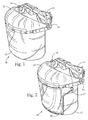
- the face protector may include an adjustable headband 11 and a frontal member 12 for supporting a lens 13.
- the frontal member 12 and lens 13 may be adjusted at an angle with the headband 11.
- Adjustment knobs 14 and 15 are available for holding the member 12 and lens 13 at the desired angle.
- the lens optical stack 16 is made and attached to the lens 13 according to the teachings of the present invention, amplified herein below.
- the lens optical stack 16 preferably includes tabs 17, which are employed by a wearer for removal of an individual layer of the lens optical stack 16. It is preferable that the removal tabs 17 do not have any adhesive on either side thereof so that a user will not pick up the adhesive on their fingers or gloves (if worn).
- the lens optical stack 16 becomes contaminated and blocks the user's view, then one simply reaches up and grabs an individual tab 17 and peels off an outer layer of the lens optical stack 16. This process may be repeated as many times as there are layers in the lens optical stack 16.
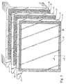
- FIG. 3 a partially exploded view of the multi-ply transparent optical stack 16 is shown.
- This figure illustrates removable Mylar lenses or film layers 30, 32, 34, 36 ... alternating with adhesive layers 31, 33, 35 .... That is, the film layer 30 is held to the film layer 32 by the clear uninterrupted adhesive layer 31 interposed there between. The next film layer 34 is held to the film layer 32 by interposing the adhesive layer 33 there between, and so forth for formation of the entire lens optical stack 16.
- the preferred material used to form the film layers 30, 32, 34, etc. is preferably a clear polyester.
- the layers are preferably fabricated from sheets of plastic film sold under the registered trademark Mylar owned by the DuPont Company and more particularly a type of Mylar made from a clear polymer polyethylene terephalate, commonly referred to as PET.
- the preferred adhesive layers 31, 33, 35 etc. used to laminate the lenses together sequentially is a clear optical low tack material.
- the thickness of each film layer typically ranges from .5 mil to 7 mil (1 mil is .001"). The preferred thickness is 2 mil. Even after the adhesive material is applied to a 2 mil thickness layer, the thickness of the 2 mil thickness layer will still be 2 mil due to the adhesive film layer having only a nominal thickness.
- the adhesive material 20 comprises a water based acrylic optically clear adhesive or an oil based clear adhesive, with the water based adhesive being the preferred embodiment.
- the thickness of each adhesive layer is negligible even though the adhesive layers are illustrated in as distinct layers.
- a preferred adhesive layer/film layer construction is disclosed in our pending application serial no. 09/449,318 filed November 24, 1999 entitled Optical Stack of Laminated Removable Lenses for Face Shields, Windows, and Displays, published as US6388813.
- a cut is made around the periphery of the bottom-most film layer 30, thereby exposing a narrow strip 20 of the adhesive layer 31.
- the strip 20 is used for adhesively affixing the optical stack 16 to the face protector 10. It is preferable to make the peripheral cut after the optical stack 16 is assembled into the multiple alternating layers in order to maintain proper registration of the individual layers.
- the narrow strip 20 may be applied separately to the bottom most film layer 30 as well.
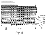
- FIG 4 a partial cross-sectional view taken along line 4-4 of Figure 3 illustrates a detail of alternating film layers 30, 32, 34, 36 ..., with the adhesive layers 31, 33, 35, ... interposed between each the film layers.
- the peripheral cut exposing the strip 20 only removes a portion of the bottom-most film layer 30.
- This narrow peripheral strip 20 is preferably 1 ⁇ 8" to 1 ⁇ 2" in width, or wider. The more narrow the strip the more likely the stack will not stay in place on the face protector and the wider the strip the more likely the bubble problem, discussed above, will occur.
- the preferred width is as stated above, i.e., 1 ⁇ 8" to 1 ⁇ 2" in width.
- the multiply transparent optical stack 16 of the present invention can be easily applied to any desired face protector 10 by positioning the bottom-most film layer 30 having the narrow strip 20 of adhesive layer disposed about the periphery thereof adjacent to the front surface of the face protector. A user may then press the narrow strip 20 of the adhesive layer 31 against the outer surface of the face protector 10 causing the stack to be rapidly mounted thereto.
- the narrow strip 20 is attached to the face protector 10 adjacent one end thereof and subsequently spread or pressed tightly against the front surface of the face protector 10.
- air bubbles or the like are not presented at the interface of the optical stack 16 and the face protector 10.
- the optical stack 16 has adhesive layers there between, reflection between the film layers 30 is substantially reduced.
- the user may quickly remove the upper most film layer from the stack exposing a clean film layer there below.
- the present invention allows an effective optical stack to be rapidly deployed upon any optical surface and be rapidly used by a user.
Landscapes
- Physics & Mathematics (AREA)
- General Physics & Mathematics (AREA)
- Optics & Photonics (AREA)
- Eyeglasses (AREA)
- Prostheses (AREA)
- Packages (AREA)
- Adhesives Or Adhesive Processes (AREA)
- Led Device Packages (AREA)
Claims (11)
- Optischer Stapel (16) aus laminierten abziehbaren Linsen zum Aufkleben auf einem Gesichtsschutzschild, welcher umfasst:(a) eine Vielzahl von übereinander gestapelten abziehbaren Linsen (30,32,34,36,...), welche klebend aneinander gefügt sind;(b) wobei jede abziehbare Linse an jeder nachfolgenden Linse mit einer durchsichtigen ununterbrochenen Klebeschicht (31,33,35,...) befestigt ist, welche zwischen jeder abziehbaren Linse aufgebracht ist;(c) wobei jede Linse einen Abziehlaschenabschnitt (17) an zumindest einem Ende aufweist, und wobei der Abziehlaschenabschnitt auf beiden Seiten keine Klebeschicht aufweist, um den Träger des Gesichtsschutzschilds zu ermöglichen, schnell den Abziehlaschenabschnitt zu greifen, zum Abziehen der obersten Linse, und zum Freilegen einer sauberen Linse direkt unterhalb der abgezogenen obersten Linse; gekennzeichnet durch:(d) eine unterste abziehbare Linse (30) des Stapels mit einem Klebeband (20), ausgebildet entlang des Umfangs der Linse zum Befestigen des Stapels an dem Gesichtsschutzschild, wobei das Klebeband eine Dichtlippe bildet, und dadurch jede Feuchtigkeit von der Verbindungsfläche zwischen der untersten Linse und dem Gesichtsschutzschild fernhält.
- Optischer Stapel gemäß Anspruch 1, wobei das Klebeband (20) gebildet wird, indem ein Schnitt in die Tiefe der untersten Linse (30) eingebracht wird, innerhalb des Umfangs und entlang der Linsenform, wodurch der äußerste, gewöhnlich ringförmige Abschnitt dann abgetrennt wird, und wobei dadurch der Kleber der vorherigen Schicht freigelegt wird, welcher dazu beiträgt, die Linse an dem Gesichtsschutzschild zu befestigen.
- Optischer Stapel gemäß Anspruch 1, wobei das Klebeband (20) an dem Umfang der untersten Linse angebracht ist.
- Optischer Stapel gemäß Anspruch 1, wobei die abziehbaren Linsen und die durchsichtigen Klebeschichten einen Brechungsindex zwischen 1,4 und 1,52 aufweisen.
- Optischer Stapel (16) aus abziehbaren Linsen zum Aufkleben auf einem optischen Fenster, welcher umfasst:(a) eine Vielzahl von gewöhnlich rechteckigen, übereinander gestapelten, abziehbaren Linsen (30,32,34,36,...), welche klebend aneinander gefügt sind, um den optischen Stapel zu bilden;(b) wobei jede abziehbare Linse an jeder nachfolgenden Linse mit einer durchsichtigen ununterbrochenen Klebeschicht (31,33,35,...) befestigt ist, welche zwischen jeder abziehbaren Linse aufgebracht ist;(c) eine Vielzahl von versetzt angeordneten Laschen (17), welche von einer Ecke von jeder der Filmschichten abstehen, wobei die Laschen zur Unterstützung angebracht sind, um zu ermöglichen, dass jede Filmschicht nacheinander abgezogen wird; und(d) wobei die unterste abziehbare Linse (30) des Stapels ein Klebeband (20) aufweist, welches entlang des Umfangs davon ausgebildet ist, um den Stapel an dem optischen Fenster zu befestigen, wobei das Klebeband eine Dichtlippe bildet, und dadurch Feuchtigkeit von der Verbindungsfläche zwischen der untersten Linse und dem optischen Fenster fernhält.
- Optischer Stapel gemäß Anspruch 5, wobei das optische Fenster, an welchem der Stapel aus abziehbaren Linsen befestigt ist, umfasst, ein Windschutzschild, ein Fenster, ein Gesichtsschutzschild oder ein Videodisplay.
- Optischer Stapel gemäß Anspruch 5, wobei das Klebeband (20) ausgebildet wird, indem ein Schnitt in die Tiefe der untersten Linse (30) eingebracht wird, innerhalb des Umfangs und entlang der Linsenform, wobei der äußerste, gewöhnlich ringförmige Abschnitt dann entfernt wird, und wobei dadurch der Klebstoff der vorherigen Schicht freigelegt wird, welcher dazu beiträgt, die Linse an dem optischen Fenster zu befestigen.
- Optischer Stapel gemäß Anspruch 5, wobei das Klebeband (20) an dem Umfang der untersten Linse (30) angebracht ist.
- Optischer Stapel gemäß Anspruch 5, wobei die abziehbaren Linsen und die durchsichtigen Klebeschichten einen Brechungsindex zwischen 1,4 und 1,52 aufweisen.
- Optischer Stapel gemäß Anspruch 5, wobei die Laschen (17) keinen darauf aufgebrachten Klebstoff aufweisen.
- Verfahren zum Bilden eines Stapels (16) aus optischen Linsen zur Befestigung an einem optischen Fenster, wobei das Verfahren die nachfolgenden Schritte umfasst:(a) das Aufeinanderlaminieren einer Vielzahl von Schichten (30,32,34,36,...) aus optischen Linsen, indem eine durchsichtige, ununterbrochene Klebeschicht (31,33,35,...) zwischen jede Schicht aus einer optischen Linse, welche laminiert wird, aufgebracht wird;(b) das Bilden einer Laschenerweiterung (17) bei jeder Schicht aus einer optischen Linse, und das Weglassen der Klebeschicht bei der Laschenerweiterung, wobei jede Linsenschicht einzeln abgezogen werden kann; und(c) das Schneiden entlang dem Umfang und in die Tiefe einer Lage aus einer optischen Linse der untersten Schicht (30) des optischen Stapels, wobei dadurch ein Klebestreifen (20) freigelegt wird, um den optischen Stapel (16) an dem optischen Fenster anzukleben.
Applications Claiming Priority (3)
| Application Number | Priority Date | Filing Date | Title |
|---|---|---|---|
| US39519 | 1997-03-03 | ||
| US10/039,519 US6536045B1 (en) | 1999-11-24 | 2002-01-03 | Tear-off optical stack having peripheral seal mount |
| PCT/US2002/010971 WO2003060563A2 (en) | 2002-01-03 | 2002-04-09 | Tear-off optical stack having peripheral seal mount |
Publications (3)
| Publication Number | Publication Date |
|---|---|
| EP1502146A2 EP1502146A2 (de) | 2005-02-02 |
| EP1502146A4 EP1502146A4 (de) | 2005-04-20 |
| EP1502146B1 true EP1502146B1 (de) | 2006-07-05 |
Family
ID=21905904
Family Applications (1)
| Application Number | Title | Priority Date | Filing Date |
|---|---|---|---|
| EP02806423A Expired - Lifetime EP1502146B1 (de) | 2002-01-03 | 2002-04-09 | Optischer abreissstapel mit umfangsversiegelungsanbringung |
Country Status (5)
| Country | Link |
|---|---|
| EP (1) | EP1502146B1 (de) |
| AT (1) | ATE332510T1 (de) |
| AU (1) | AU2002366993A1 (de) |
| DE (1) | DE60213009T2 (de) |
| WO (1) | WO2003060563A2 (de) |
Cited By (1)
| Publication number | Priority date | Publication date | Assignee | Title |
|---|---|---|---|---|
| WO2025257620A1 (en) * | 2024-06-10 | 2025-12-18 | Thi Total Healthcare Innovation S.r.l. | Protection lens for surgical use having removable layers |
Families Citing this family (5)
| Publication number | Priority date | Publication date | Assignee | Title |
|---|---|---|---|---|
| WO2010044029A1 (en) * | 2008-10-16 | 2010-04-22 | Koninklijke Philips Electronics N.V. | Imaging device and method |
| WO2016089695A1 (en) | 2014-12-05 | 2016-06-09 | 3M Innovative Properties Company | Vision-protecting filter lens |
| US20170266929A1 (en) | 2016-03-17 | 2017-09-21 | Racing Optics, Inc. | Rigid Display Shield |
| KR101882310B1 (ko) * | 2016-04-22 | 2018-07-27 | 주식회사 오토스윙 | 투시창 보호용 투명필름시트가 결합된 안면 보호구 |
| DE102018210680A1 (de) * | 2018-06-29 | 2020-01-02 | Trumpf Laser Gmbh | Optisches Element mit abziehbarer Schutzfolie |
Family Cites Families (9)
| Publication number | Priority date | Publication date | Assignee | Title |
|---|---|---|---|---|
| US2511329A (en) * | 1946-12-26 | 1950-06-13 | Craig Edward | Lens shield |
| US4076373A (en) * | 1976-03-10 | 1978-02-28 | E. D. Bullard Company | Method of and means for shielding the lens of a face mask |
| US4138746A (en) * | 1977-03-28 | 1979-02-13 | Bergmann Donald W | Face shield protective system and apparatus |
| US4716601A (en) * | 1986-08-05 | 1988-01-05 | Scott Usa Limited Partnership, A Washington Limited Partnership | Tear-off lens system and method for goggles |
| GB2269239A (en) * | 1992-07-28 | 1994-02-02 | Andrew Thomas Moore | Protective visors for motor cycle helmet visors |
| US5671483A (en) * | 1995-06-06 | 1997-09-30 | Ontario Limited | Removable subsidiary helmet face shield lens |
| US5592698A (en) * | 1995-06-30 | 1997-01-14 | Woods; Marlen M. | Tear-off lens for transparent eye and face shield |
| CA2211755A1 (en) * | 1997-05-27 | 1998-11-27 | Kevin Cogan | Vision enhancing tear off shield guards |
| US6388813B1 (en) * | 1999-11-24 | 2002-05-14 | Bart Wilson | Optical stack of laminated removable lenses for face shields windows and displays |
-
2002
- 2002-04-09 WO PCT/US2002/010971 patent/WO2003060563A2/en not_active Ceased
- 2002-04-09 AT AT02806423T patent/ATE332510T1/de not_active IP Right Cessation
- 2002-04-09 AU AU2002366993A patent/AU2002366993A1/en not_active Abandoned
- 2002-04-09 EP EP02806423A patent/EP1502146B1/de not_active Expired - Lifetime
- 2002-04-09 DE DE60213009T patent/DE60213009T2/de not_active Expired - Lifetime
Cited By (1)
| Publication number | Priority date | Publication date | Assignee | Title |
|---|---|---|---|---|
| WO2025257620A1 (en) * | 2024-06-10 | 2025-12-18 | Thi Total Healthcare Innovation S.r.l. | Protection lens for surgical use having removable layers |
Also Published As
| Publication number | Publication date |
|---|---|
| AU2002366993A1 (en) | 2003-07-30 |
| EP1502146A2 (de) | 2005-02-02 |
| WO2003060563A2 (en) | 2003-07-24 |
| ATE332510T1 (de) | 2006-07-15 |
| DE60213009T2 (de) | 2007-02-01 |
| WO2003060563A3 (en) | 2004-11-18 |
| DE60213009D1 (de) | 2006-08-17 |
| EP1502146A4 (de) | 2005-04-20 |
| AU2002366993A8 (en) | 2003-07-30 |
Similar Documents
| Publication | Publication Date | Title |
|---|---|---|
| US6536045B1 (en) | Tear-off optical stack having peripheral seal mount | |
| US12557867B2 (en) | Adhesive mountable stack of removable layers | |
| US12038789B2 (en) | Touch screen shield | |
| US9471163B2 (en) | Touch screen shield | |
| EP1012638B1 (de) | Lichtfilternde linsenbeschichtung | |
| US6388813B1 (en) | Optical stack of laminated removable lenses for face shields windows and displays | |
| EP3429845B1 (de) | Starrer anzeigeschutz | |
| EP1517791B1 (de) | Optischer stapel von laminierten entfernbaren gläsern | |
| KR20210069581A (ko) | 김서림-방지 렌즈 커버링 시스템 | |
| EP1502146B1 (de) | Optischer abreissstapel mit umfangsversiegelungsanbringung | |
| JPH10165600A (ja) | 遊技機用の前面開閉扉 | |
| WO2014021903A1 (en) | Touch screen shield |
Legal Events
| Date | Code | Title | Description |
|---|---|---|---|
| PUAI | Public reference made under article 153(3) epc to a published international application that has entered the european phase |
Free format text: ORIGINAL CODE: 0009012 |
|
| 17P | Request for examination filed |
Effective date: 20040728 |
|
| AK | Designated contracting states |
Kind code of ref document: A2 Designated state(s): AT BE CH CY DE DK ES FI FR GB GR IE IT LI LU MC NL PT SE TR |
|
| AX | Request for extension of the european patent |
Extension state: AL LT LV MK RO SI |
|
| A4 | Supplementary search report drawn up and despatched |
Effective date: 20050309 |
|
| RIC1 | Information provided on ipc code assigned before grant |
Ipc: 7G 02B 27/14 A Ipc: 7A 61F 9/02 B Ipc: 7A 42B 3/26 B |
|
| GRAP | Despatch of communication of intention to grant a patent |
Free format text: ORIGINAL CODE: EPIDOSNIGR1 |
|
| GRAS | Grant fee paid |
Free format text: ORIGINAL CODE: EPIDOSNIGR3 |
|
| GRAA | (expected) grant |
Free format text: ORIGINAL CODE: 0009210 |
|
| AK | Designated contracting states |
Kind code of ref document: B1 Designated state(s): AT BE CH CY DE DK ES FI FR GB GR IE IT LI LU MC NL PT SE TR |
|
| PG25 | Lapsed in a contracting state [announced via postgrant information from national office to epo] |
Ref country code: IT Free format text: LAPSE BECAUSE OF FAILURE TO SUBMIT A TRANSLATION OF THE DESCRIPTION OR TO PAY THE FEE WITHIN THE PRESCRIBED TIME-LIMIT;WARNING: LAPSES OF ITALIAN PATENTS WITH EFFECTIVE DATE BEFORE 2007 MAY HAVE OCCURRED AT ANY TIME BEFORE 2007. THE CORRECT EFFECTIVE DATE MAY BE DIFFERENT FROM THE ONE RECORDED. Effective date: 20060705 Ref country code: BE Free format text: LAPSE BECAUSE OF FAILURE TO SUBMIT A TRANSLATION OF THE DESCRIPTION OR TO PAY THE FEE WITHIN THE PRESCRIBED TIME-LIMIT Effective date: 20060705 Ref country code: LI Free format text: LAPSE BECAUSE OF FAILURE TO SUBMIT A TRANSLATION OF THE DESCRIPTION OR TO PAY THE FEE WITHIN THE PRESCRIBED TIME-LIMIT Effective date: 20060705 Ref country code: AT Free format text: LAPSE BECAUSE OF FAILURE TO SUBMIT A TRANSLATION OF THE DESCRIPTION OR TO PAY THE FEE WITHIN THE PRESCRIBED TIME-LIMIT Effective date: 20060705 Ref country code: FI Free format text: LAPSE BECAUSE OF FAILURE TO SUBMIT A TRANSLATION OF THE DESCRIPTION OR TO PAY THE FEE WITHIN THE PRESCRIBED TIME-LIMIT Effective date: 20060705 Ref country code: NL Free format text: LAPSE BECAUSE OF FAILURE TO SUBMIT A TRANSLATION OF THE DESCRIPTION OR TO PAY THE FEE WITHIN THE PRESCRIBED TIME-LIMIT Effective date: 20060705 Ref country code: CH Free format text: LAPSE BECAUSE OF FAILURE TO SUBMIT A TRANSLATION OF THE DESCRIPTION OR TO PAY THE FEE WITHIN THE PRESCRIBED TIME-LIMIT Effective date: 20060705 |
|
| REG | Reference to a national code |
Ref country code: GB Ref legal event code: FG4D |
|
| REG | Reference to a national code |
Ref country code: CH Ref legal event code: EP |
|
| REG | Reference to a national code |
Ref country code: IE Ref legal event code: FG4D |
|
| REF | Corresponds to: |
Ref document number: 60213009 Country of ref document: DE Date of ref document: 20060817 Kind code of ref document: P |
|
| PG25 | Lapsed in a contracting state [announced via postgrant information from national office to epo] |
Ref country code: SE Free format text: LAPSE BECAUSE OF FAILURE TO SUBMIT A TRANSLATION OF THE DESCRIPTION OR TO PAY THE FEE WITHIN THE PRESCRIBED TIME-LIMIT Effective date: 20061005 Ref country code: DK Free format text: LAPSE BECAUSE OF FAILURE TO SUBMIT A TRANSLATION OF THE DESCRIPTION OR TO PAY THE FEE WITHIN THE PRESCRIBED TIME-LIMIT Effective date: 20061005 |
|
| PG25 | Lapsed in a contracting state [announced via postgrant information from national office to epo] |
Ref country code: ES Free format text: LAPSE BECAUSE OF FAILURE TO SUBMIT A TRANSLATION OF THE DESCRIPTION OR TO PAY THE FEE WITHIN THE PRESCRIBED TIME-LIMIT Effective date: 20061016 |
|
| NLV1 | Nl: lapsed or annulled due to failure to fulfill the requirements of art. 29p and 29m of the patents act | ||
| PG25 | Lapsed in a contracting state [announced via postgrant information from national office to epo] |
Ref country code: PT Free format text: LAPSE BECAUSE OF FAILURE TO SUBMIT A TRANSLATION OF THE DESCRIPTION OR TO PAY THE FEE WITHIN THE PRESCRIBED TIME-LIMIT Effective date: 20061205 |
|
| EN | Fr: translation not filed | ||
| PLBE | No opposition filed within time limit |
Free format text: ORIGINAL CODE: 0009261 |
|
| STAA | Information on the status of an ep patent application or granted ep patent |
Free format text: STATUS: NO OPPOSITION FILED WITHIN TIME LIMIT |
|
| 26N | No opposition filed |
Effective date: 20070410 |
|
| PG25 | Lapsed in a contracting state [announced via postgrant information from national office to epo] |
Ref country code: GR Free format text: LAPSE BECAUSE OF FAILURE TO SUBMIT A TRANSLATION OF THE DESCRIPTION OR TO PAY THE FEE WITHIN THE PRESCRIBED TIME-LIMIT Effective date: 20061006 Ref country code: FR Free format text: LAPSE BECAUSE OF FAILURE TO SUBMIT A TRANSLATION OF THE DESCRIPTION OR TO PAY THE FEE WITHIN THE PRESCRIBED TIME-LIMIT Effective date: 20070511 |
|
| PG25 | Lapsed in a contracting state [announced via postgrant information from national office to epo] |
Ref country code: IE Free format text: LAPSE BECAUSE OF NON-PAYMENT OF DUE FEES Effective date: 20070409 |
|
| PG25 | Lapsed in a contracting state [announced via postgrant information from national office to epo] |
Ref country code: FR Free format text: LAPSE BECAUSE OF FAILURE TO SUBMIT A TRANSLATION OF THE DESCRIPTION OR TO PAY THE FEE WITHIN THE PRESCRIBED TIME-LIMIT Effective date: 20060705 |
|
| PG25 | Lapsed in a contracting state [announced via postgrant information from national office to epo] |
Ref country code: MC Free format text: LAPSE BECAUSE OF NON-PAYMENT OF DUE FEES Effective date: 20070430 |
|
| PG25 | Lapsed in a contracting state [announced via postgrant information from national office to epo] |
Ref country code: LU Free format text: LAPSE BECAUSE OF NON-PAYMENT OF DUE FEES Effective date: 20070409 Ref country code: CY Free format text: LAPSE BECAUSE OF FAILURE TO SUBMIT A TRANSLATION OF THE DESCRIPTION OR TO PAY THE FEE WITHIN THE PRESCRIBED TIME-LIMIT Effective date: 20060705 |
|
| PG25 | Lapsed in a contracting state [announced via postgrant information from national office to epo] |
Ref country code: TR Free format text: LAPSE BECAUSE OF FAILURE TO SUBMIT A TRANSLATION OF THE DESCRIPTION OR TO PAY THE FEE WITHIN THE PRESCRIBED TIME-LIMIT Effective date: 20060705 |
|
| PGRI | Patent reinstated in contracting state [announced from national office to epo] |
Ref country code: IT Effective date: 20110616 |
|
| PGFP | Annual fee paid to national office [announced via postgrant information from national office to epo] |
Ref country code: IT Payment date: 20210427 Year of fee payment: 20 Ref country code: DE Payment date: 20210408 Year of fee payment: 20 |
|
| PGFP | Annual fee paid to national office [announced via postgrant information from national office to epo] |
Ref country code: GB Payment date: 20210408 Year of fee payment: 20 |
|
| REG | Reference to a national code |
Ref country code: DE Ref legal event code: R071 Ref document number: 60213009 Country of ref document: DE |
|
| REG | Reference to a national code |
Ref country code: GB Ref legal event code: PE20 Expiry date: 20220408 |
|
| PG25 | Lapsed in a contracting state [announced via postgrant information from national office to epo] |
Ref country code: GB Free format text: LAPSE BECAUSE OF EXPIRATION OF PROTECTION Effective date: 20220408 |