EP1502032B1 - Oberleitung schiene anker-system - Google Patents
Oberleitung schiene anker-system Download PDFInfo
- Publication number
- EP1502032B1 EP1502032B1 EP03709497A EP03709497A EP1502032B1 EP 1502032 B1 EP1502032 B1 EP 1502032B1 EP 03709497 A EP03709497 A EP 03709497A EP 03709497 A EP03709497 A EP 03709497A EP 1502032 B1 EP1502032 B1 EP 1502032B1
- Authority
- EP
- European Patent Office
- Prior art keywords
- cavity
- component
- opening
- members
- head
- Prior art date
- Legal status (The legal status is an assumption and is not a legal conclusion. Google has not performed a legal analysis and makes no representation as to the accuracy of the status listed.)
- Expired - Lifetime
Links
- 230000015572 biosynthetic process Effects 0.000 claims abstract description 85
- 238000005755 formation reaction Methods 0.000 claims abstract description 85
- 230000006641 stabilisation Effects 0.000 claims description 62
- 238000011105 stabilization Methods 0.000 claims description 62
- 230000006835 compression Effects 0.000 claims description 8
- 238000007906 compression Methods 0.000 claims description 8
- 238000006073 displacement reaction Methods 0.000 claims description 7
- 230000002441 reversible effect Effects 0.000 claims description 4
- 230000002401 inhibitory effect Effects 0.000 claims description 3
- 230000000670 limiting effect Effects 0.000 claims description 3
- 230000001939 inductive effect Effects 0.000 claims description 2
- 230000036961 partial effect Effects 0.000 description 16
- 230000007246 mechanism Effects 0.000 description 6
- 230000000295 complement effect Effects 0.000 description 3
- 238000003780 insertion Methods 0.000 description 3
- 230000037431 insertion Effects 0.000 description 3
- 239000002023 wood Substances 0.000 description 3
- 238000004873 anchoring Methods 0.000 description 2
- 230000000903 blocking effect Effects 0.000 description 2
- 108010001267 Protein Subunits Proteins 0.000 description 1
- 229910000831 Steel Inorganic materials 0.000 description 1
- 238000010276 construction Methods 0.000 description 1
- 230000005484 gravity Effects 0.000 description 1
- 238000009434 installation Methods 0.000 description 1
- 230000007774 longterm Effects 0.000 description 1
- 238000000034 method Methods 0.000 description 1
- 230000000750 progressive effect Effects 0.000 description 1
- 239000007858 starting material Substances 0.000 description 1
- 239000010959 steel Substances 0.000 description 1
Images









Classifications
-
- F—MECHANICAL ENGINEERING; LIGHTING; HEATING; WEAPONS; BLASTING
- F16—ENGINEERING ELEMENTS AND UNITS; GENERAL MEASURES FOR PRODUCING AND MAINTAINING EFFECTIVE FUNCTIONING OF MACHINES OR INSTALLATIONS; THERMAL INSULATION IN GENERAL
- F16B—DEVICES FOR FASTENING OR SECURING CONSTRUCTIONAL ELEMENTS OR MACHINE PARTS TOGETHER, e.g. NAILS, BOLTS, CIRCLIPS, CLAMPS, CLIPS OR WEDGES; JOINTS OR JOINTING
- F16B21/00—Means for preventing relative axial movement of a pin, spigot, shaft or the like and a member surrounding it; Stud-and-socket releasable fastenings
- F16B21/02—Releasable fastening devices locking by rotation
-
- F—MECHANICAL ENGINEERING; LIGHTING; HEATING; WEAPONS; BLASTING
- F16—ENGINEERING ELEMENTS AND UNITS; GENERAL MEASURES FOR PRODUCING AND MAINTAINING EFFECTIVE FUNCTIONING OF MACHINES OR INSTALLATIONS; THERMAL INSULATION IN GENERAL
- F16B—DEVICES FOR FASTENING OR SECURING CONSTRUCTIONAL ELEMENTS OR MACHINE PARTS TOGETHER, e.g. NAILS, BOLTS, CIRCLIPS, CLAMPS, CLIPS OR WEDGES; JOINTS OR JOINTING
- F16B37/00—Nuts or like thread-engaging members
- F16B37/04—Devices for fastening nuts to surfaces, e.g. sheets, plates
- F16B37/045—Devices for fastening nuts to surfaces, e.g. sheets, plates specially adapted for fastening in channels, e.g. sliding bolts, channel nuts
-
- F—MECHANICAL ENGINEERING; LIGHTING; HEATING; WEAPONS; BLASTING
- F16—ENGINEERING ELEMENTS AND UNITS; GENERAL MEASURES FOR PRODUCING AND MAINTAINING EFFECTIVE FUNCTIONING OF MACHINES OR INSTALLATIONS; THERMAL INSULATION IN GENERAL
- F16B—DEVICES FOR FASTENING OR SECURING CONSTRUCTIONAL ELEMENTS OR MACHINE PARTS TOGETHER, e.g. NAILS, BOLTS, CIRCLIPS, CLAMPS, CLIPS OR WEDGES; JOINTS OR JOINTING
- F16B5/00—Joining sheets or plates, e.g. panels, to one another or to strips or bars parallel to them
- F16B5/06—Joining sheets or plates, e.g. panels, to one another or to strips or bars parallel to them by means of clamps or clips
- F16B5/0685—Joining sheets or plates to strips or bars
-
- F—MECHANICAL ENGINEERING; LIGHTING; HEATING; WEAPONS; BLASTING
- F16—ENGINEERING ELEMENTS AND UNITS; GENERAL MEASURES FOR PRODUCING AND MAINTAINING EFFECTIVE FUNCTIONING OF MACHINES OR INSTALLATIONS; THERMAL INSULATION IN GENERAL
- F16B—DEVICES FOR FASTENING OR SECURING CONSTRUCTIONAL ELEMENTS OR MACHINE PARTS TOGETHER, e.g. NAILS, BOLTS, CIRCLIPS, CLAMPS, CLIPS OR WEDGES; JOINTS OR JOINTING
- F16B7/00—Connections of rods or tubes, e.g. of non-circular section, mutually, including resilient connections
- F16B7/18—Connections of rods or tubes, e.g. of non-circular section, mutually, including resilient connections using screw-thread elements
- F16B7/187—Connections of rods or tubes, e.g. of non-circular section, mutually, including resilient connections using screw-thread elements with sliding nuts or other additional connecting members for joining profiles provided with grooves or channels
-
- A—HUMAN NECESSITIES
- A61—MEDICAL OR VETERINARY SCIENCE; HYGIENE
- A61G—TRANSPORT, PERSONAL CONVEYANCES, OR ACCOMMODATION SPECIALLY ADAPTED FOR PATIENTS OR DISABLED PERSONS; OPERATING TABLES OR CHAIRS; CHAIRS FOR DENTISTRY; FUNERAL DEVICES
- A61G7/00—Beds specially adapted for nursing; Devices for lifting patients or disabled persons
- A61G7/10—Devices for lifting patients or disabled persons, e.g. special adaptations of hoists thereto
- A61G7/104—Devices carried or supported by
- A61G7/1042—Rail systems
-
- A—HUMAN NECESSITIES
- A61—MEDICAL OR VETERINARY SCIENCE; HYGIENE
- A61G—TRANSPORT, PERSONAL CONVEYANCES, OR ACCOMMODATION SPECIALLY ADAPTED FOR PATIENTS OR DISABLED PERSONS; OPERATING TABLES OR CHAIRS; CHAIRS FOR DENTISTRY; FUNERAL DEVICES
- A61G7/00—Beds specially adapted for nursing; Devices for lifting patients or disabled persons
- A61G7/10—Devices for lifting patients or disabled persons, e.g. special adaptations of hoists thereto
- A61G7/1073—Parts, details or accessories
- A61G7/1076—Means for rotating around a vertical axis
Definitions
- the present invention relates to mechanisms for the fixation of support runners, tracks, rails and the like to an overhead structure and in particular for the for fixation of runners, tracks, rails and the like for lifting and transferring loads.
- the overhead structure may for example be the ceiling in room, corridor and the like of buildings such as hospitals, residential and long-term care centers, residential custodial care facilities as well as private homes.
- Overhead support and displacement structures are known, for example, for lifting and transferring loads as well as for maintaining fixtures such as lighting devices in place (for the latter please see US patent no. 5653412 ).
- Overhead handling systems are, in particular, known for lifting and transferring people.
- Such systems may comprise a trolley component and an overhead track component for guiding the trolley along a predetermined path.
- a trolley component may take on any suitable (known) form which allows it to be supported by and glide along a track component, i.e. such that a trolley component may be moved manually along the track or may be so moved by providing a suitable motorised trolley displacement system; please also see for example U.S. patent no. 6,085,368 which relates to a winch for such a person handling system.
- Overhead track components are also known wherein a track is either directly bolted or otherwise fixed to the ceiling of a room.
- the fasteners for an overhead track component may, for example, be an extruded latch bracket such as is disclosed in GB 2216857 . They are built in the runner and used frequently with bolting components. In any case such fasteners are bolted in some manner to the ceiling support structure
- US 5,051,047 relates to a clamping apparatus for clamping an object to a member having an opening therein and marginal portions defining, in part, said opening.
- the apparatus includes a first member engageable with the object and having a first threaded portion. The first threaded portion is in threaded engagement with a second threaded portion complementary to the first threaded portion, the second threaded portion being on a base member having first and second opposite side portions.
- the apparatus further includes engaging members for engaging the marginal portions adjacent to the opening, the engaging members having distal and proximal end portions, the proximal end portions being pivotely connected to the first and second opposite side portions of the base, respectively.
- the distal end portions have respective contact surfaces for engaging the marginal portions about the opening.
- an attachment means or mechanism by which an overhead track support may be relatively easy to install It would also be advantageous to have such a mechanism which would facilitate the removal of the track once initially set in place. It would be further advantageous to have an attachment means which could be used to provide an an esthetic attachment of a track to a ceiling.
- anchoring mechanism of the present invention will be described hereinafter with respect to overhead track systems for displacing a person, it is to be understood that the anchoring mechanism may be used in the context of overhead track support systems for the displacement of other types of loads as well as for merely supporting objects which are not necessarily to be intended to be (regularly) displaced along a track.
- the flarable member may take on any desired or necessary form or configuration, keeping in mind the purpose thereof, namely, to jam in a holding cavity of a mounting element for mounting a load bearing track to a hanger component attached to an overhead structure (e.g. a ceiling or ceiling structure).
- an overhead structure e.g. a ceiling or ceiling structure
- a anchor assembly for mounting a load bearing track to an overhead structure (e.g. a ceiling or ceiling structure), said track having a longitudinal extent (i.e. length dimension) and comprising a rail element and a mounting element, said mounting element comprising one or more retaining formations, each retaining formation defining a holding cavity and an (cavity) opening communicating with the holding cavity, said holding cavity being sized larger than the (cavity) opening communicating therewith, the anchor assembly comprising a hanger component (shank) attached to an overhead structure (e.g.
- a ceiling or ceiling structure and a head component
- said head component comprising, a support member and a flarable member, said support member being connected to the hanger component, said flarable member being attached to and flarable from said support member, said head component being sized and configured such that said head component is able to pass through a said (cavity) opening into said holding cavity wherein the flarable member is able to flare (i.e. to open or spread outwardly) so as to present a flared formation in the holding cavity sized larger than the (cavity) opening so as to inhibit withdrawal of the head component in the holding cavity back through the opening.
- a combination kit for mounting a load bearing track to an overhead structure (e.g. a ceiling or ceiling structure), said load bearing track having a longitudinal extent and comprising a rail element and a mounting element, said mounting element comprising one or more retaining formations, each retaining formation defining a holding cavity and a respective (cavity) opening communicating with the holding cavity, said holding cavity being sized larger than the respective (cavity) opening communicating therewith, said combination kit comprising one or more head components, each head component comprising a support member and a flarable member attached to and flarable from said support member, said head component being sized and configured such that said head component is able to pass through a respective (cavity) opening into said holding cavity wherein the flarable member is able to flare (i.e.
- a hanger component for attaching a respective head component to the overhead structure (e.g. a ceiling or ceiling structure) and a section of said load bearing track.
- a combination kit as defined herein may comprise one or more hanger component for attaching a respective head component to the overhead structure (e.g. a ceiling or ceiling structure); and/or one or more sections of said load bearing track
- the rail element and said mounting element may integral; alternatively they may be releasebly attachable in any suitable (known) manner.
- a mounting element may comprise one or more retainer formations each defining a discrete (slot-like) opening, i.e. a mounting element may comprise a plurality (i.e. two or more) of discrete (cavity) openings and in particular a plurality (i.e. two or more) of discrete elongated slot-like (cavity) openings.
- a mounting element may comprise an elongated retainer formation extending the longitudinal extent of the track, said elongated retainer formation defining a slot-like (cavity) opening extending the longitudinal extent of the track.
- a combination kit as defined herein may comprise one or more a lateral stabilization components, each said lateral stabilization component comprising an attachment member (i.e.opening) connecting the lateral stabilization component to a respective hanger component, said lateral stabilization component being displaceable between a non-wedging configuration and a lodging or wedging configuration in the slot-like (cavity) opening for inhibiting lateral movement of the mounting element transverse to the longitudinal extent of the track.
- attachment member i.e.opening
- the flarable member may take on any desired form or configuration keeping in mind its intended purpose.
- the flarable member may comprise two or more wing blade or plate members such as described herein by way of example only.
- a head component for an anchor assembly, for mounting a load bearing track to a hanger component attached to an overhead structure (e.g. a ceiling or ceiling structure), said track comprising a rail element and a mounting element, said mounting element comprising one or more retaining formations, each retaining formation defining a holding cavity and a (cavity) opening communicating with the holding cavity, said holding cavity being sized larger than the opening communicating therewith, the head component comprising a support member and a pair of opposed engagement (i.e..
- each of said wing blade members being pivotally attached to the support member by a respective pivot connect member, said head component being sized and configured such that said head component is able to pass through said opening into said holding cavity wherein each of the wing blade members are able to pivot outwardly in said holding cavity so as to each engage the retaining formation to create a respective truss formation which acts as a reverse wedge to resist pull out of the head component from the holding cavity through the opening, said truss formation having a base chord defined by the retaining formation, a side chord defined by the wing blade member and a center strut defined by the support member.
- a wing blade or plate member may comprise a single unit as described by way example herein below. However, if desired or necessary a wing plate or blade member may comprise two or more individual sub-units; in this case wing plate or blade member as well as the pivot connect member a respective pivot connect member must be configured or adapted as necessary keeping in mind the purpose of the wing blade members, i.e. to be able to enter the holding cavity and jam the head component in a holding cavity so as to inhibit removal of the head component back out the (cavity) opening.
- a head component may or may not be provided with biasing means for biasing the wing blade members in a flared position.
- the head component may be provided with stop elements for arresting the rotation of the wing blade members beyond a desired or predetermined angle, i.e. the rotation is constrained between a predetermined range of angular displacement about of rotation.
- the retaining formation may include in the holding cavity members which serve to limit such rotation of the wing blade members, e.g. if no stop members is provided for this purpose, i.e. to facilitate engagement between the portion of the retaining formation defining the (cavity) opening so as to form said truss structure(s).
- An anchor assembly for mounting a load bearing track to an overhead structure (e.g. a ceiling or ceiling structure), said track having a longitudinal extent (i.e. length dimension) comprising a rail element and a mounting element, said mounting element comprising one or more retaining formations, each retaining formation defining a holding cavity and an (cavity) opening communicating with the holding cavity, said holding cavity being sized larger than the (cavity) opening communicating therewith, the anchor assembly comprising a hanger component (shank) attached to an overhead structure (e.g. a ceiling or ceiling structure) and a head component said head component being as defined above as comprising wing blade (plate) members, said support member being connected to said hanger component.
- an overhead structure e.g. a ceiling or ceiling structure
- an anchor assembly as defined herein wherein when the (cavity) opening has a slot-like configuration and a longitudinal extent, the anchor assembly further comprises a lateral stabilization component, said lateral stabilization component comprising a head member, for gripping the lateral stabilization element for the rotation thereof, and an insert member extending from said head member, said insert member having a rectangular configuration and comprising a pair of opposed outer long sides and a pair of opposed outer short sides said insert member being configured such that said insert member is insertable into the slot-like opening when the long sides of the insert member extend parallel to the longitudinal extent of the slot-like opening, and is pivotable - rotatable in the slot-like opening with respect to the longitudinal extent of the opening so as to dispose the long sides of the insert member transverse to the longitudinal extent of the rail such that the short sides of the insert member engage the retaining formation defining the slot-like opening so as to (or for) inhibit(ing) lateral (sideways) movement of the mounting element transverse (i.e. movement in a direction transverse (e
- An anchor assembly as provided herein may be one wherein the hanger component comprises a shank member having a longitudinal extent, said head and insert members define a sleeve body having a sleeve opening, said shank member extending through said sleeve opening, said sleeve body and said shank member being configured for rotational displacement of the lateral stabilization component about the longitudinal extent of the shank member (i.e. about the longitudinal axis of the shank member).
- An anchor assembly as provided herein may be one wherein the insert member comprises a pair of opposed tab members, each tab member extending from a respective short side of the insert member, said insert member being configured such that said tab members are insertable through the slot-like (cavity) opening into the holding cavity, said tab members, said wing blade members and said retaining formation being configured such that when the tab members are in the holding cavity and the short sides of the insert member are made to engage the retaining formation each wing blade member is engaged by (i.e. sandwiched or pinched between) a respective tab member and the retaining formation.
- An anchor assembly as provided herein may comprise a compression inducing component for placing the wing blade members under compression stress between the retaining formation and said pivot connect member.
- an anchor assembly as defined herein may be one wherein said anchor assembly comprises a pair of opposed base members, each base member projecting from a respective side of said support member, a pair of brace members and a pair of cam members, each brace member comprising a head member and a distal engagement member, each base member being associated with a respective brace member and a respective cam member, each base member and respective brace and cam members being configured such that said head member is able to abut the outside surface of the portion of the retaining formation defining said opening, said distal engagement member is able to pivotally - rotationally engage said base member and when said brace member is rotated said cam member places said brace member under tension stress so as to urge said pivot connect member to urge said wing blade members connected thereto against the retaining formation and thereby placing the wing blade members under compression stress between the retaining formation and said pivot connect member.
- An anchor assembly as provided herein may comprise a stabilization component, the stabilization component comprising a head member, for gripping the stabilization element for the rotation thereof, and an insert member extending from said head member, the insert member comprising a pair of opposed tab members spaced apart from (e.g.
- insert member and the opening being configured such that said insert member including said tab members is insertable into opening with the tab members extending parallel to the longitudinal axis - direction of the rail such that said tab members are insertable through the slot-like opening into the holding cavity, and said tab members, said wing blade members and said retaining formation being configured such that when the tab members are in the holding cavity said insert member including said tab members is pivotable - rotatable with respect to the longitudinal extent of the opening so as to dispose the tab members transverse to the longitudinal axis of the rail such that each wing blade member is engaged by (i.e. sandwiched between) a respective tab member and the retaining formation.
- a combination kit is further provided for mounting a load bearing track to an overhead structure (e.g. a ceiling or ceiling structure), said load bearing track having a longitudinal extent and comprising a rail element and a mounting element, said mounting element comprising one or more retaining formations, each retaining formation defining a holding cavity and a respective (cavity) opening communicating with the holding cavity, said holding cavity being sized larger than the respective (cavity) opening communicating therewith, said combination kit comprising one or more head components as comprising (support) wing blade (plate) members, and one or more members selected from the class consisting of a hanger component for attaching a respective head component to the overhead structure (e.g. a ceiling or ceiling structure) and a section of said load bearing track.
- an overhead structure e.g. a ceiling or ceiling structure
- said load bearing track having a longitudinal extent and comprising a rail element and a mounting element, said mounting element comprising one or more retaining formations, each retaining formation defining a holding cavity and a respective (ca
- a stop element may be provided for limiting the wing blade member(s) to a predetermined degree of rotation relative to the support member, e.g. once the wing blade members are in a holding cavity they may unfold outwardly by a predetermined degree of rotation.
- the head component itself may for example be provided with such a stop element; the stop element may comprise a plurality of sub-units, e.g. each wing blade member may be associated with a respective stop element unit.
- the holding cavity itself may comprise such a stop element.
- both the head component and the holding cavity may be provided with such stop element units.
- a lateral stabilization component and/or a brace member may be provided with alignment indicator members, the visibility of which from below is indicative of whether or not a lateral stabilization component or a brace member has been rotated, i.e. the visibility of the indicator members from below is indicative that a lateral stabilization component or a brace member has not been rotated to a locking position as discussed by way of example herein; on the other hand if an indicator member is hidden from view by the track this is indicative that a lateral stabilization component or a brace member has been rotated to a locking position.
- the present invention may advantageously be used by a single person for the mounting of a track attachable thereto to a ceiling or other overhead structure since the head component once inside the holding cavity will already maintain the track in place.
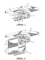
- FIG. 1 illustrate, an example embodiment of an anchor assembly 1 in accordance with the present invention.
- the anchor assembly 1 comprises a track anchor head component designated generally by the reference numeral 3, a lateral stabilization component designated generally by the reference numeral 5 and a hanger component.
- the hanger component is designated generally by the reference numeral 7.
- the hanger component 7 comprises a threaded shank or shaft 9.
- One end (i.e. the upper end) of the shank (not shown) is connected to the ceiling or ceiling structure in any known or suitable manner examples of which shall be described in more detail below; as may also be seen, for illustration purposes Figure 1 and 9 as well as other figures mentioned herein a portion of a false or suspended ceiling 11 will be shown.
- the head component 3 is connected to other or lower end 13 of the threaded shank or shaft 7 and is releasably held thereto by a bolt/washer combination, wherein the bolt is designated by the reference numeral 14 and the washer by the reference numeral 15.
- Figure 2 shows the anchor assembly 1 of Figure 1 associated with a track 17 the side walls of which are partially cut away so as to show the C-shaped cross section of the mounting element 19 and the lower rail element 21 as well as the disposition of the head component 3 in the holding cavity 23a of the mounting element 19 of the track 17
- the mounting element 19 is integral with the rail element 21 and each as mentioned above are of C-shaped cross section.
- the side walls 23 and 24 of the mounting element 19 function as an elongated retaining formation in that they define the elongated holding cavity 23a and an elongated slot (cavity) opening 25; more particularly the side walls 23 and 24 have free edge portions 27 and 29 which are bent inwardly towards each other and are spaced apart so as to define said elongated slot (cavity) opening 25.
- the holding cavity 23a defines a space which is larger or wider in extent than the elongated slot (cavity) opening 25, i.e. the width of the cavity 23a is larger than the space or distance between the free edge portions 27 and 29 defining the slot (cavity) opening 25.
- the rail element may be used to engage a displaceable trolley component such as is described in U.S. patent no. 6,085,368 .
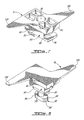
- Figures 3 to 6 illustrate the head component 3, and more particularly its support member 31 and its flarable member 33.
- Figure 3 also shows the head component in association with the example lateral stabilization component 5 which shall be described below in more detail.
- the flarable member 33 comprises a pair of opposed engagement wing blades or plates 35 and 36, each wing blade or plate 35 and 36 being pivotally attached to the support member31 by a respective two part pivot connect member on a side of the support member 31 opposite to the other wing plate member.
- each of the wing plates 35, 36 comprises a wing body 38 from which a pair of spaced apart foot elements 40 and 42 extend; the wing body 38 and foot elements 40, 42 give the wing plate a generally U-shaped appearance.
- a pivot pin or toe element 44 extends outwardly from each foot element 40, 42.
- the pivot connect member for wing plate 35 comprises a pair of opposed pin or toe openings 46 for pivotally engaging a respective pin or toe element 44 of the wing blade or plate 35 (see also figure 3 which shows the pin or toe element 44 disposed in a respective pin or toe opening 46); the openings 46 are each defined by an upper projection and a lower stop element 48 or 50.
- the pivot connect member for wing plate 35 also includes, adjacent each pin opening, an angled stop element 48 or 50; the stop elements 48, 50 are configured and angled so as to be able to engage a respective foot element 40, 42 so as to allow the wing plate 35 to only be able to pivot up to a predetermined rotational angle ⁇ as shown in Figure 6 with respect to the support member 31, i.e. the wing plate 35 is only able to fold outwardly and inwardly within a predetermined degree of rotation relative to the support member 31.
- the angle ⁇ is of course to be chosen keeping in mind the purpose of the wing plates, i.e. to participate in the provision of a truss structure as described herein (e.g. the rotational angle ⁇ may be from about 0 to about 30 degrees or less).
- the stop elements 48, 50 may if desired be configured for a greater degree (e.g. an angle ⁇ of from about 0 to about 45 degrees or less) or lesser degree (e.g. an angle ⁇ of from about 0 to about 25 degrees or less) of rotation of the wing plate 35 or even be dispensed with entirely provided that a lower support element is maintained for defining the lower portion of the pin openings 46.
- wing plate 35 In the absence of the stop elements the wing plate 35 will be free to rotate to a greater degree; however, in such case the mounting of a track 17 to such a head component 3 will require more manipulation by an installer since the installer will have to manually configure the wing plate 35 disposition for insertion of the head component 3 through the (cavity) opening 25 of a mounting element 19.
- the retaining formation should be configured to include one or more blocking members which are so disposed so as to maintain the wing blade members in an upwardly extending configuration in the holding cavity such as set forth in the figures whereby the ends of the wing blade member may act on the upper free edge portions of the to create a truss structure.
- a blocking structure may alternatively be incorporated or associated with a wing member itself.
- wing blade members In any event, the purpose of the wing blade members should always be kept in mind as well as their ability to fold up for passage through the (cavity) opening 25 or any other opening which may be used by a mounting element and once in the holding cavity to fold outwardly a sufficient degree so as to participate in the provision of a truss structure as described herein.
- the other wing plate or blade 36 and its respective pivot connect member (hidden from view) are of the same construction described above with respect to the wing plate 35 and its pivot connect member.
- the central portion 52 of the support member 31 which separates the stop elements 48, 50 defines a recessed space 54 and is provided with an attachment opening 56 (i.e. a connection member) for receiving the end 13 of the threaded shank.
- the attachment opening 56 communicates with the recessed space 54; the so defined recessed structure is to act as a recessed seat for receiving the bolt/washer combination 14/15 when the bolt 14 thereof is threaded to the end 13 of the shank passing through the attachment opening 56 for releasably attaching the support member 31 to the lower end 13 of the shank (i.e. to the hanger component) (see Figure 1 ).
- the lateral stabilization component 5 has an attachment member which in the embodiment shown comprises a sleeve opening 58. More particularly, the lateral stabilization component 5 comprises a head member 60, for gripping the lateral stabilization element for the rotation thereof, and an insert member 62 extending from the head member 60; i.e. the head and insert members define a sleeve body which defines the above mentioned sleeve opening 58.
- the sleeve opening 58 is used for connecting the lateral stabilization component 5 to the hanger component (i.e. to end 13 of the shank).
- the lateral stabilization component 5 as shall be discussed in more detail below is displaceable about the shank between a non-wedging configuration and a lodging or wedging configuration in the slot like (cavity) opening 25 of the mounting element 19 for inhibiting lateral (i.e. wobble) movement of the mounting element 19 transverse to the longitudinal extent of the track 17.
- the insert member 62 has a rectangular configuration and comprises a pair of opposed outer long sides 54 and a pair of opposed outer short sides 66. Diagonally opposed corners 68 of the insert member 62 are beveled or rounded to facilitate rotation of the insert member 62 in the mounting element (cavity) opening 25 as shall be discussed below.
- the insert member 62 shown also comprises a pair of opposed tab members 70, each tab member 70 extending from a respective short side 66 of the insert member 62. Each tab member70 is spaced apart from a respective opposite portion of the head member 60, by a portion of the insert member 62 so as to define an open ended U-shaped like structure.
- the U-shaped like structure is configured such that when the insert member 62 is in the above mentioned wedging configuration in the slot like (cavity) opening 25, a respective free edge portion 27 (or 29) extends into the opening of the U-shaped like structure such that not only does the short side 66 of the insert member 62 embrace (i.e. engages) the respective free edge portion 27 (or 29) but so does the tab member 70 and the opposed portion of the head member (see for example Figure 22 and 23 ).
- the tab member and the opposed portion of the head member may be so spaced apart that one or both of them is not able to embrace the above mentioned respective free edge portion 27 (or 29).
- the tab members 70 are rotated from their initial in-line position (i.e.
- the anchor assembly 1 may comprise one or more other stabilization components which are of different or similar configuration to the lateral stabilization component 5 described above; such different stabilization component 5 may be used in place of the lateral stabilization component described above or, as shall be described herein, in addition thereto.
- Such other stabilization components may thus, for example, provide the above mentioned wedging function as well as a clamping function (as discussed below); alternatively the other stabilization components instead of providing both of such functions may only provide one of them, e.g. the clamping function.
- the clamping function may, in particular, be exploited to provide the anchor assembly with a track interconnection ability, i.e.
- each track 17 has an end retaining formation of C-shaped cross-section disposed at an end of the rail thereof, the ends of the arms of the C-shape defining a first slot-like (cavity) opening 25, the end retaining formation further defining at the end of the mounting element 19 a respective end C-shaped opening communicating with said holding cavity 23a.
- a suitably configured anchor assembly may thus further acti as a track interconnection component for interconnecting respective end retaining formations of two tracks 17, the ends of the rails thereof being juxtaposed (see for example Figure 26 ).
- Such an alternate stabilization component may exploit a brace member 75 as illustrated in Figure 8 .
- the support member 31 may as illustrated in Figures 3 and 4 , also or in the alterative be associated with a pair of base members 77 and 79 which are connected to the support member 31 on opposite sides thereof.
- the base members 77 and 79 are each intended to cooperate with a respective brace member 75 for (releasably) urging the pivot connect member(s) to urge the wing blades 35, 36 connected thereto against the retaining formation and thereby placing the wing blades 35, 36under compression stress between the retaining formation and said pivot connect member (i.e. to provide a type of clamping action wherein the retaining formation is sandwiched between the brace members 75 and the wing plates 35, 36).
- each brace member 75 comprises a head member 81, for gripping the connector member for the rotation thereof, an intermediate member 83 and a distal (i.e. foot) engagement member 85 which is connected to the intermediate member 83 by a stem member 87; the distal (i.e. foot) engagement member 85 has a longitudinal extent, i.e. it has a rectangle-like shape with rounded corners 89.
- each base member 77 (and 79) has a primary opening or cavity 91 which extends longitudinally more or less parallel to the attachment opening, 56 the cross section of the primary opening 91has a shape complementary to the shape of the foot engagement member 85 such that the longitudinal extent thereof is parallel to the longitudinal extent of the support member 31 (i.e. both extend along the axis designated by the reference numeral 93 in Figures 3 and 4 ).
- the intermediate member 83 is sized larger than the mouth of the primary opening 91.
- the foot member 85 when its longitudinal extent is aligned or lined up with the longitudinal extent of the support member 31(see axis 93) is sized and configured so as to be able to enter the primary opening 91 just sufficiently to be disposed adjacent opposed cam openings 95.
- the side walls defining a primary opening 91 also define the opposed cam openings or slots 95; i.e. each primary opening 91 is associated with a pair of opposed cam openings 95.
- the cam openings 95 are configured for receiving the above mentioned (i.e. foot) engagement member 85.
- the cam openings 95 are each wider at one side thereof but with the narrow portion of one cam slot being opposite the wider portion of the opposed cam slot, i.e.
- cam slot 95 for base member 77 the shown slot 95 gradually narrows down from side 97 to the other side 99.
- the upper engagement surfaces 100 of the opposed cam slots 95 thus can act as an overall cam surface for urging a downward displacement of the (i.e. foot) engagement member 85 when the foot engagement member 85 is rotated such that its longitudinal extent is transvers to the longitudinal extent of the support member, (i.e. transverse to the axis 93 in Figures 3 and 4 ) .
- each brace member 75 as illustrated additionally is provided with an insert member101 extending from the head member 81 so as to be between the intermediate member 83 and the head member 81.
- the insert member 101 for the brace member 75 has the same configuration as the insert member 62 for lateral stabilization component 5 described above (see Figure 7 ); the insert member 101 for the brace member 75 thus also has a rectangular configuration and comprises a pair of opposed outer long sides, a pair of opposed outer short sides as well as a pair of diagonally opposed round corners.
- the insert member 101 for the brace member 75 can provide for the same sort of lateral stability as that of the lateral stabilization component 5.
- the insert member 101 for the brace member 75 may, on the other hand, be sized and configured to present a body smaller than the slot (cavity) opening 25 of the mounting element 19 such that rotation of the brace member 75 does not bring about a wedging of its insert member 101 in the slot (cavity) opening 25.
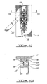
- the head members 60 and 81 for the lateral stabilization component 5 and the brace members 75 are shown in Figures 7 and 8 as being provided with gripping wings 102 for being gripped by the fingers of an installer for rotation of thereof; these wings 102, if present, may also serve as indicators that the associated lateral stabilization component 5 or brace member 75 has or has not been rotated into a locking configuration, i.e. namely, if the wings 120 are aligned as shown in Figure 29 so as to be visible from below then there is no wedging but if the wings are aligned as shown in figure 31 so as to be hidden from view from below then an insert member is wedged in the slot (cavity) opening 25 as discussed herein.
- the gripping wings 102 may alternatively be dispensed with in which case rotation may be solely induced by that use of a suitable tool such as the wrench like tool shown in Figures 18 and 19 .
- FIGS 9 to 15 show the steps for the formation of the anchor assembly 1 i.e. the installation or connection of various elements of the anchor assembly to the shank which has been previously connected to the ceiling overhead structure.
- the shank projects out of the surface of a false ceiling 11 ( Figure 9 ); see below for various connection type for the shank to a ceiling or ceiling structure.
- a disc shaped abutment plate 104 having a central opening through which the shank extends may first be attached to the ceiling surface (e.g. by any suitable known attachment means e.g. screws); i.e. the shank is slipped through the central opening of the disc and the disc is placed against the ceiling surface where after screws (not shown) are then passed through screw openings (not shown) in the plate and screwed in place so as to secure the disc up against the ceiling surface.
- a head component 3 associated with a lateral stabilization component 5 (as shown in Figure 3 ) is slipped onto the end 13 of the shank i.e. the end 13 of the shank is passed through the sleeve opening 58 of the stabilization component 5 and then through the attachment opening 56 of the support member 31 whereupon the bolt/washer combination 14/15 is attached to the end 13 of the shank, i.e.
- the anchor assembly 1 is as shown in figure 11 ; in this configuration the lateral stabilization component 5 abuts the support member3 as well as the disc plate 104 but is still able to be rotated about the shank.
- the head component 3 may also be associated with a pair of brace members 75 so as to provide an anchor assembly 106 (see Figure 24 ) with the above mentioned other stabilization component(s).
- the track comprises a mounting element and a rail element each of which as mentioned above is of C-shaped cross section.
- the side walls of the mounting element function also as mentioned above, as an elongated retaining formation in that they define an elongated holding cavity and an elongated slot opening; more particularly the side walls have free edge portions which are bent inwardly towards each other and are spaced apart so as to define said elongated slot (cavity) opening.
- the holding cavity defines a space which is larger in extent than the elongated slot opening, i.e. the width of the cavity is larger the space or distance between the free edge portions defining the slot (cavity) opening.
- the head component 3 is sized and configured such that the head component 3, when its longitudinal extent is placed parallel to the longitudinal extent of the elongated slot (cavity) opening, is able to pass through slot (cavity) opening 25 into the holding cavity 23a wherein the flarable member (i.e. wing plates 35, 36) is able to flare (i.e. to open or spread outwardly) so as to present a flared formation in the holding cavity 23a sized larger than the (cavity) opening 25 so as to inhibit withdrawal of the head component 3 in the holding cavity 23a back through the (cavity) opening 25
- the flarable member i.e. wing plates 35, 36
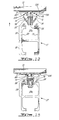
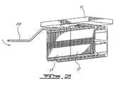
- Figures 12 to 15 show the progressive insertion of the head component 3 through the slot (cavity) opening 25 into the holding cavity 23a and the ultimate disposition of the head component 3 in the holding cavity 23a of the mounting element 19 of the track17.
- Figure 12 shows the head component 3 with its longitudinal extent lined up with the longitudinal extent of the slot (cavity) opening 25.
- the slot opening 25 is displaced upwardly in the direction of the arrow 108 towards the head component 3
- the wing plates 35, 36 thereof eventually impinge upon the free edge portions 27, 29 defining the slot opening 25 and are displaced inwardly in the direction of the arrows 110.
- the wings plates 35 and 36 are folded up the head component 3 as seen in Figure 13 proceeds through the slot (cavity) opening 25.
- the head component 3 is sized and configured such that the head component3 is able to pass through the slot (cavity) opening 25 into the holding cavity 23a wherein each of the wing blades 35, 36 are able to pivot outwardly in said holding cavity 23a so as to each engage the retaining formation to create a respective truss-like formation which acts as a reverse wedge to resist pull out of the head component from the holding cavity through the opening;
- the truss-like formation comprises an assemblage of members arranged in a triangle or combination of triangles to form a rigid framework.
- each of the truss-like formations has a base chord defined more or less by a respective free edge portion 27, 29 of the retaining formation, a side chord defined by the wing blade 35, 36 and a center strut defined by the support member 31.
- Figures 16 and 17 are perspective views illustrating the insertion of the head component 3 through the slot (cavity) opening 25 into the holding cavity 23a as shown above in Figures 12 to 14
- the mounting element 19 (and thus the track 17 as a whole) may still wobble laterally along its longitudinal extent (in the direction of the arrows 109) about the head component 3 (see Figure 19 ). Accordingly, it is desirable to inhibit such movement and recourse for this purpose may be made to the lateral stabilization element.
- Figures 18 to 22 show the rotation of the lateral stabilization element 5 by the tool 110 (which grips the head member 3) from an initial in longitudinally in-line position (see Figures 18 to 20 ) to an intermediate transverse position ( Figure 21 ) to the final more or less perpendicular disposition shown in Figure 22 .
- the tab members are rotated from their initial in-line position (i.e. in-line with the longitudinal extent of the slot opening) into their final transverse position they will tend to urge the wing plates 35, 36 apart to ensure that the upper edges 71 of the wing plates 35, 36 extend well into the holding cavity 23a under respective free edge portions 27, 29 of the retaining formation.
- the head member 60 of the lateral stabilization element 5 is configured for being gripped by the tool 110 for the rotation of the lateral stabilization element 5 by the tool 110; rotation is in the direction of lowest resistance as provided by the diagonally rounded corners 68.
- the head member 60 is sized in longitudinal extent larger than the width of slot-like opening 25.
- the tool 110 has jaws which define an opening of shape complementary to the shape of the head component 3.
- the insert member 62 also as may be seen from Figures 19 to 22 is configured such that the insert member 62 is insertable into the slot-like (cavity) opening 25 when the long sides 64 of the insert member extend parallel to the longitudinal extent (axis 112) of the slot-like (cavity) opening 25, and is pivotable (i.e. rotatable) in the slot-like (cavity) opening 25 with respect to the longitudinal extent of the (cavity) opening 25 so as to dispose the long sides 64 of the insert member transverse to the longitudinal extent of the (cavity) opening 25 such that the short sides 66 of the insert member 62 engage the retaining formation defining the slot-like opening 25 (i.e.
- the free edge portions 27, 29 thereof so as to (or for) inhibit(ing) lateral (sideways) movement of the mounting element 19 transverse (i.e. movement in a direction transverse (e.g. at right angles - perpendicular)) to the longitudinal extent of the track 17.
- the insert member 62 as mentioned includes tab members 70.
- the tab members 70 are configured such that the tab members 70 are also insertable through the slot-like (cavity) opening 25 into the holding cavity 23a.
- the tab members 70, the wing blades 35, 36 and the retaining formation are configured such that when the tab members 70 are in the holding cavity 23a and the short sides 66 of the insert member 62 have been made to engage the free edge portions 27,29 of the retaining formation, each wing blade 35, 36 is engaged by (i.e. sandwiched between) a respective tab member 70 and the retaining formation
- the insert member 62 for the lateral stabilization component 5 is shown as being sized to wedge in the slot-like opening, the insert member 62 may, in an alternate embodiment, be sized smaller than the slot like opening 25.
- the tab members 70 alone may not only serve to (if necessary) push apart and maintain the wing blades 35, 36 apart but also to engage the wing blade 35, 36 against the retaining formation (e.g. mounting element side walls) so as to (or for) inhibit(ing) lateral (sideways) movement of the mounting element 19 transverse (i.e. movement in a direction transverse (e.g. at right angles - perpendicular)) to the longitudinal extent of the track 17 i.e. to act as a stabilization component
- Figure 23 illustrates a modified version of the example embodiment of the head component 3 shown in Figure 3 .
- the head component shown in Figure 23 is the same as that shown in Figure 3 except that the embodiment in Figure 23 includes a pair of bias springs 115; the bias springs 115 are configured so as to tend to urge the wing plates 35, 36 to remain in the flared position but are so chosen that they do not interfere with the folding back of the wing plates 35, 36 as the head component is forced into the holding cavity 23a through the slot (cavity) opening 25.
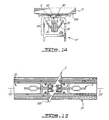
- FIGS. 24 to 27 these Figures illustrate the mounting of the adjacent ends of a pair of the tracks 17 (i.e. tracks 17 as described above with respect to Figures 12 to 14 ) using the alternate anchor assembly embodiment shown in Figure 24 ; the embodiment being the same as that shown in Figures 1 and 11 except that the assembly includes a pair of brace members 75 as shown in Figure 8 .
- the mounting process is the same as that discussed above with respect to Figures 12 to 14 and 20 to 22 , i.e. the same steps are followed so as to wedge the insert member 62 of the lateral stabilization component 5 into the slot opening 25.
- each brace member 75 is associated with a respective base member 77, 79.
- each brace member 75 has a head member 81, an insert member 101, an intermediate member 83, a stem member 87 and a distal or foot engagement member 85.
- FIGS 26 , 27 and 29 show each of the brace members 75 in the initial mounting configuration wherein the members such as the insert member 101 as well as the foot member 85 have their longitudinal extents aligned or lined up (i.e. in-line) with the longitudinal extent of the support member (see axis112). Thus each foot member 85 is adjacent a respective pair of cam openings 95.
- each brace member 75 and respective base member 77, 79 are configured such that the head member 81 of the brace member 75 is rotatable from the in-line position shown in the figures 26 , 27 and 29 to the transverse position (as shown in Figure 31 a) .
- the head member 81 is able to be brought into abutment with the outside surface of the portion of the free edge portions 27, 29 of the retaining formation defining the slot (cavity) opening 25.
- the longitudinally opposed ends of the the distal or foot engagement member 85 are each able to be pivotally (i.e. rotationally) inserted into a respective cam opening 95 so as to engage the upper cam surfaces 100 thereof.
- the brace member 75 acts against the upper cam surfaces 100 tending to place the stem member 87 , etc. under tension stress.
- FIGs 28 , 29 , 29a , 30 , 30a , 31 and 31a illustrate the rotation of the brace member 75 by the same type tool 110 used for rotation of the lateral stabilization component 5 (which grips the head member) from an initial in longitudinally in-line position (see Figure 29a ) to an intermediate transverse position ( Figure 30a ) to the final more or less perpendicular or transverse disposition shown in Figure 31a .
- the distal or foot engagement members 85 are rotated from their initial in-line position (i.e.
- FIG. 32 shows another example embodiment of a track wherein the mounting element has a retaining formation structure that provides a plurality (i.e. one or more, e.g. two or more) of distinct elongated (cavity openings) 130.
- Figures 33, 34 and 35 these figures illustrate example for attaching an elongated stem of a shank projecting out of a false ceiling 11 to an upper (ceiling) support structure.
- Figure 33 shows the upper end of the stem 135 being attached to a concrete structure 137; the attachment may be by any known mechanism e.g. by a screw anchor disposed in a hole in the concrete surface, the end of the stem being provided with screw threads for being threaded into the anchor 136 so as to compress the anchor 136 against the hole wall.
- Figure 34 shows a stem 135 being attached to a steel girder 140 by a bolt/washer combination 142, the end of the stem being provided with screw threads for engagement with corresponding threads of the bolt.
- Figure 35 shows the stem 135 being attached to a wood beam 144, the end of the stem 135 having a screw configuration for being screwed directly into the wood beam 144 or into a starter hole initially drilled therein.
Landscapes
- Engineering & Computer Science (AREA)
- General Engineering & Computer Science (AREA)
- Mechanical Engineering (AREA)
- Joining Of Building Structures In Genera (AREA)
- Supports For Pipes And Cables (AREA)
- Installation Of Indoor Wiring (AREA)
- Vehicle Body Suspensions (AREA)
- Paper (AREA)
- Platform Screen Doors And Railroad Systems (AREA)
- Railway Tracks (AREA)
- Invalid Beds And Related Equipment (AREA)
- Nitrogen And Oxygen Or Sulfur-Condensed Heterocyclic Ring Systems (AREA)
- Saccharide Compounds (AREA)
- Shaping Of Tube Ends By Bending Or Straightening (AREA)
- Snaps, Bayonet Connections, Set Pins, And Snap Rings (AREA)
- Clamps And Clips (AREA)
Claims (16)
- Kombination zum Befestigen einer Lauflcatzen-Tragschiene (17) an einer Aufhängekomponente (7), die an einer Überkopf-Struktur (11) befestigt ist,
wobei die Laufkatzen-Tragschiene (17) ein Schienenelement (21) und ein Lagerelement (14) umfasst, welches Lagerelement (19) eine oder mehrere Halteformationen aufweist, von denen jede Formation einem Haltehohlraum (23a) und eine mit dem Haltehohlraum (23a) kommunizierende Hohlraumöffnung (25) definiert, wobei der Haltehohlraum (23a) größere Ausmaße als die mit ihm kommunizierende Hohlraumöffnung (25) aufweist,
wobei die Kombination aufweist
eine Kopfkomponente (3),
und
eine Seitenstabilisierungskomponente (5),
wobei die Kopfkomponente (3) ein Tragelement (31) und ein Abspreizelement (33), aufweist, wobei das Abspreizelement (33) an dem Tragelement (31) befestigt und von ihm abspreizbar ist,
wobei die Kopfkomponente (3) so dimensioniert und geformt ist, das die Kopfkomponente (3) durch die Hohlraumöffnung (25) hindurch in den Haltehohlraum (23a) eintreten kann, in welchem das Abspreizelement (31) sich nach außen abspreizen kann, um in dem Haltehohlraum (23a) eine aufgeweitete Form einzunehmen, die breiter ist als die Hohlraumöffnung (25), um ein Herausziehen der Kopfkomponente (31) aus dem Haltehohlraum (23a) zurück durch die Hohlraumöffnung (25) zu verhindern,
und wobei das Seitenstabilisierungselement (5) ein Befestigungselement zum Verbinden des Seitenstabilisierungselements (5) mit der Aufhängekomponente (7) aufweist, wobei das Seitenstabilisierungselement (5) zwischen einer nicht klemmenden Anordnung und einer Klemmanordnung in der Hohlraumöffnung (25) verschiebbar ist, um eine seitliche Bewegung des Lagerelements (19) quer zu der Längserstreckung der Laufkatzen-Tragschiene (17) zu verhindern. - Kombination nach Anspruch 1, mit einem Verbindungselement zum lösbaren Verbinden des Tragelements (31) mit der Aufhängekomponente (7).
- Kombination nach Anspruch 1, bei der das Spreizelement (33) ein Paar von einander gegenüberliegenden Eingriffs-Flügelelementen (35, 36) aufweist, von denen jedes schwenkbar an dem Tragelement (31) über ein jeweiliges Schwenkverbindungselement (44) befestigt ist, wobei die Kopfkomponente (3) solche Abmessungen und Formgebung hat, dass die Kopfkomponente (3) durch die Hohlraumöffnung (25) in den Haltehohlraum (23a) hindurchtreten kann, in welchem jedes der Flügelelemente (35, 36) in dem Haltehohlraum (23a) ausschwenken kann, um in die Halteformation einzugreifen und eine jeweilige Fachwerkformation zu bilden, die als Gegenkeil gegen ein Herausziehen der Kopfkomponente (3) aus dem Haltehohlraum (23a) durch die Hohlraumöffnung (25) wirkt,
wobei die Fachwerkformation einen von der Halteformation gebildeten Basisgurt, einen von dem jeweiligen Flügelelement (35, 36) gebildeten Seitengurt und einen von dem Tragelement (31) gebildeten Zentralgurt aufweist. - Kombination nach Anspruch 3, mit einem Verbindungselement zum lösbaren Verbinden der Tragelemente (31) mit der Aufhängekomponente (7).
- Kombination nach Anspruch 3, mit einem Anschlagelement (48, 52) zum Begrenzen jedes Flügelelements (35, 36) auf einen vorgegebenen Rotationswinkel relativ zu dem Tragelement (31).
- Kombination nach Anspruch 1, bei der das Tragelement (31) der Kopfkomponente (3) mit der an der Überkopfkonstruktion (11) befestigten Aufhängekomponente (7) verbunden ist.
- Kombination nach Anspruch 6, bei der die Kopfkomponente (3) ein Verbindungselement zur lösbaren Verbindung des Tragelements (31) mit der Aufhängekomponente (7) aufweist.
- Kombination nach Anspruch 6, bei der das Spreizelement (33) ein Paar von einander gegenüberliegenden Eingriffs-Flügelelementen (35, 36) aufweist, von denen jedes schwenkbar an dem Tragelement (31) über ein jeweiliges Schwenkverbindungselement (44) befestigt ist, wobei die Kopfkomponente (3) solche Abmessungen und Formgebungen hat, dass die Kopfkomponente (3) durch die Hohlraumöffnung (25) in den Haltehohlraum (23a) hindurchtreten kann, in welchem jedes der Flügelelemente (35, 36) in dem Haltehohlraum (23a) ausschwenken kann, um in die Halteformation einzugreifen und eine jeweilige Fachwerkformation zu bilden, die als Gegenkeil gegen ein Herausziehen der Kopfkomponente (3) aus dem Haltehohlraum (23a) durch die Hohlraumöffnung (25) wirkt,
wobei die Fachwerkformation einen von der Halteformation gebildeten Basisgurt, einen von dem jeweiligen Flügelelement (35, 36) gebildeten Seitengurt und einen von dem Tragelement (31) gebildeten Zentralgurt aufweist. - Kombination nach Anspruch 8, bei der die Kopfkomponente (3) ein Verbindungselement zur lösbaren Verbindung des Tragelements (31) mit der Aufhängekomponente (7) aufweist.
- Kombination nach Anspruch 8, wobei die Hohlraumöffnung (25) eine schlitzartige Ausbildung und eine Erstreckung in Längsrichtung hat und dass das Seitenstabilisierungselement ein Kopfelement (60) zum Ergreifen des Seitenstabilisierungselements (5) für dessen Drehung und ein von dem Kopfelement (60) vorstehendes Einsatzelement (62) aufweist,
wobei das Einsatzelement (62) eine Rechteckform hat und zwei einander gegenüberliegende lange Seiten (54) und zwei einander gegenüberliegende kurze Seiten (66) aufweist, wobei das Einsatzelement (62) so konfiguriert ist, dass das Einsatzelement (62)
in die schlitzförmige Hohlraumöffnung (25) einsetzbar ist, wenn die langen Seiten (54) des Einsatzelements (62) parallel zur Längserstreckung der schlitzartigen Hohlraumöffnung (25) verlaufen, und
in der schlitzartigen Hohlraumöffnung (25) relativ zur Längerstreckung der Öffnung (25) schwenkbar ist, um die langen Seiten (54) des Einsatzelements (62) quer zur Längserstreckung der Laufkatzen-Tragschiene (17) anzuordnen derart, dass die kurzen Seiten (66) des Einsatzelements (62) an der die schlitzförmige Hohlraumöffnung (25) begrenzenden Halteformation eingreifen, um eine seitliche Bewegung des Lagerelements (19) quer zur Längserstreckung der Laufkatzen-Tragschiene (17) zu verhindern. - Kombination gemäß Anspruch 10, bei der die Aufhängekomponente (7) ein Schaftelement (9) mit Längserstreckung aufweist, dass das Kopfelement und Einsatzelement (60, 62) einen Hülsenkörper mit einer Hülsenöffnung (58) definieren; dass das Schaftelement (9) sich durch die Hülsenöffnung (58) erstreckt, wobei der Hülsenkörper und das Schaftelement (9) für eine Schwenkbewegung der Seitenstabilisierungskomponente (5) um die Längserstreckung des Schaftelements (9) herum ausgebildet sind.
- Kombination nach Anspruch 10, bei der das Einsatzelement (62) zwei einander gegenüberliegende Lappenelemente (70) aufweisen, wobei jedes Lappenelement (70) von einer jeweiligen kurzen Seite (66) des Einsatzelements (62) vorsteht, wobei das Einsatzelement (62) so ausgebildet ist, dass die Lappenelemente (70) durch die schlitzartige Hohlraumöffnung (25) in den Haltehohlraum (23a) einführbar sind und die Lappenelemente (70), die Flügelelemente (35, 36) und die Halteformation derart ausgebildet sind, dass, wenn sich die Lappenelemente (70) in dem Haltehohlraum (23a) befinden und die kurzen Seiten (66) des Einsatzelements (62) in die Halteformation eingreifen, jedes Flügelelement (35, 36) mit einem entsprechenden Lappenelement (70) und der Halteformation in Eingriff ist.
- Kombination nach Anspruch 8, mit einer Druck ausübenden Komponente, die die Flügelelemente (35, 36) zwischen der Halteformation und dem Schwenkverbindungselement mit einer Druckspannung beaufschlagt.
- Kombination nach Anspruch 8, bei der die Ankereinheit (1) zwei einander gegenüberliegende Basiselemente (77, 79), wobei jedes Basiselement (77, 79) von einer jeweiligen Seite des Halteelements (31) vorsteht, sowie zwei Klammerelemente (75) und zwei Nockenelemente aufweist, wobei jedes Klammerelement (75) ein Kopfelement (81) und ein distales Eingriffselement (85) hat, wobei jedes Basiselement (77, 79) einem jeweiligen Klammerelement (75) und einem jeweiligen Nockenelement zugeordnet ist, wobei jedes Basiselement (77, 79) und das entsprechende Klammerelement (75) und Nockenelement so ausgebildet sind, dass das Kopfelement (81) gegen die Außenfläche des die Hohlraumöffnung (25) definierenden Teils der Halteformation schlagen kann, das distale Eingriffselement (85) in Drehrichtung an dem Basiselement (77, 79) anschlagen kann, und das Nockenelement bei Drehung des Klammerelements (75) das Klammerelement (75) unter Zugspannung setzt, so dass das Schwenkverbindungselement die damit verbundenen Flügelelemente (35, 36) gegen die Halteformation drückt und dabei die Flügelelemente (35, 36) zwischen der Halteformation und dem Schwenkverbindungselement unter Druckspannung setzt.
- Kombination nach Anspruch 8, bei der die Seitenstabilisierungskomponente (5) ein Kopfteil (60) zum Ergreifen der Stabilisierungskomponente (5) für deren Drehung sowie ein von dem Kopfteil (60) abstehendes Einsatzelement (62) aufweist,
wobei das Einsatzelement (62) ein Paar von einander gegenüberliegenden Lappenelementen (70) aufweist, die von dem Kopfteil (60) beabstandet sind,
wobei das Einsatzelement (62) und die Hohlraumöffnung (25) so geformt sind, dass das Einsatzelement (62) einschließlich der Lappenelemente (70)
in die Hohlraumöffnung (25) einsetzbar ist, wobei die Lappenelemente (70) sich parallel zur Längserstreckung der Laufkatzen-Tragschiene (17) erstrecken, so dass die Lappenelemente (70) durch die Hohlraumöffnung (25) in den Haltehohlraum (23a) einführbar sind, und
die Lappenelemente (70), die Flügelelemente (35, 36) und die Halteformation derart ausgebildet sind, dass, wenn sich die Lappenelemente (70) in dem Haltehohlraum (25) befinden, das Einsatzteil (62) einschließlich der Lappenelemente (70)
um die Längserstreckung der Hohlraumöffnung (25) schwenkbar sind, um die Lappenelemente (70) quer zu der Längserstreckung der Laufkatzen-Tragschiene (17) anzuordnen, so dass jedes Flügelelement (35, 36) mit einem jeweiligen Lappenelemente (70) und der Halteformation in Eingriff ist. - Kombination nach Anspruch 8, bei der die Kopfkomponente (3) ein Anschlagelement (48, 50) zum Begrenzen jedes der Flügelelemente (35, 36) auf einen vorgegebenen Rotationswinkel relativ zu dem Tragelement (31) aufweist.
Applications Claiming Priority (3)
| Application Number | Priority Date | Filing Date | Title |
|---|---|---|---|
| CA2384032 | 2002-04-30 | ||
| CA002384032A CA2384032C (en) | 2002-04-30 | 2002-04-30 | Overhead track anchor system |
| PCT/CA2003/000454 WO2003093687A1 (en) | 2002-04-30 | 2003-03-28 | Overhead track anchor system |
Publications (2)
| Publication Number | Publication Date |
|---|---|
| EP1502032A1 EP1502032A1 (de) | 2005-02-02 |
| EP1502032B1 true EP1502032B1 (de) | 2008-03-26 |
Family
ID=29220518
Family Applications (1)
| Application Number | Title | Priority Date | Filing Date |
|---|---|---|---|
| EP03709497A Expired - Lifetime EP1502032B1 (de) | 2002-04-30 | 2003-03-28 | Oberleitung schiene anker-system |
Country Status (10)
| Country | Link |
|---|---|
| US (2) | US20030201374A1 (de) |
| EP (1) | EP1502032B1 (de) |
| JP (1) | JP2005529256A (de) |
| AT (1) | ATE390565T1 (de) |
| AU (1) | AU2003213928B2 (de) |
| CA (1) | CA2384032C (de) |
| DE (1) | DE60319974T2 (de) |
| DK (1) | DK1502032T3 (de) |
| ES (1) | ES2301783T3 (de) |
| WO (1) | WO2003093687A1 (de) |
Families Citing this family (28)
| Publication number | Priority date | Publication date | Assignee | Title |
|---|---|---|---|---|
| US8540194B2 (en) * | 2009-07-08 | 2013-09-24 | Advance Co., Ltd. | Pipe support base |
| DE102010027904A1 (de) * | 2010-04-19 | 2011-10-20 | Hilti Aktiengesellschaft | Befestigungsvorrichtung für Anbauteile an Montageschienen |
| CN105909636B (zh) * | 2010-04-26 | 2019-07-30 | 布兰金系统公司 | 用于使框架构架机械互锁的弯角件 |
| DE102010037521A1 (de) * | 2010-09-14 | 2012-03-15 | Demag Cranes & Components Gmbh | Vorrichtung zum Aufhängen einer Schiene |
| DE102010037522A1 (de) | 2010-09-14 | 2012-03-15 | Demag Cranes & Components Gmbh | Schiene für Hängebahnen, Hängekrane u. dgl. |
| DE102010037520A1 (de) | 2010-09-14 | 2012-03-15 | Demag Cranes & Components Gmbh | Anordnung aus einer Schiene und einem daran befestigten Schleifleitungshalter |
| DE102010037523A1 (de) | 2010-09-14 | 2012-03-15 | Demag Cranes & Components Gmbh | Verbindungsanordnung zweier Schienenabschnitte |
| USD682463S1 (en) * | 2012-03-06 | 2013-05-14 | Easton O. Bernard | Track lighting hanging bracket |
| US9303792B2 (en) * | 2012-07-23 | 2016-04-05 | Tracy M Heims | Pipe block support |
| US10463563B2 (en) | 2013-01-20 | 2019-11-05 | Bioness Inc. | Methods and apparatus for body weight support system |
| US9855177B2 (en) | 2013-01-20 | 2018-01-02 | Bioness Inc. | Methods and apparatus for body weight support system |
| US9682000B2 (en) | 2013-01-20 | 2017-06-20 | Bioness, Inc. | Methods and apparatus for body weight support system |
| GB2517779A (en) * | 2013-08-31 | 2015-03-04 | Opemed Europ Ltd | Track mounting system |
| WO2016077920A1 (en) * | 2014-11-17 | 2016-05-26 | Arjohuntleigh Magog Inc. | Configurable patient ceiling lift |
| AU2016354524B2 (en) | 2015-11-11 | 2021-08-05 | Bioness Medical, Inc. | Apparatus and methods for support track and power rail switching in a body weight support system |
| US20180028384A1 (en) * | 2016-08-01 | 2018-02-01 | Savaria Concord Lifts Inc. | Quarter turn track bracket (QTTB) for patient lifter ceiling track mechanism and methods thereof |
| WO2018049031A1 (en) | 2016-09-09 | 2018-03-15 | Bioness Inc. | Methods and apparatus for body weight support system |
| US10495409B2 (en) * | 2016-11-18 | 2019-12-03 | Tedder Industries, LLC | Mounting dock |
| EP3329893B1 (de) | 2016-12-01 | 2020-09-23 | Liko Research & Development AB | Gates für overhead-hubschienen |
| AU2018220931A1 (en) | 2017-02-14 | 2019-08-01 | Bioness Inc. | Methods and apparatus for body weight support system |
| US11041560B2 (en) * | 2018-03-08 | 2021-06-22 | Textron Innovations Inc. | Cam-locking system for a retractable driveshaft and method for use thereof |
| CN108584421B (zh) * | 2018-07-12 | 2024-01-19 | 中铁武汉电气化局集团有限公司 | 一种用于整体吊弦预配全自动生产设备的心形环送料机构 |
| EP3636238B1 (de) | 2018-10-12 | 2021-04-28 | Liko Research & Development AB | Tore mit übergangsrampen für deckenhubschienen |
| CN113454347B (zh) * | 2019-02-21 | 2023-12-22 | J·范瓦尔拉芬私人控股有限公司 | 具有扭矩诱导元件的槽形件紧固件 |
| WO2020181139A1 (en) * | 2019-03-05 | 2020-09-10 | Bedford Systems Llc | Spring biased box clip |
| US11725686B1 (en) * | 2019-08-13 | 2023-08-15 | Yakattack, Llc | Rotation locking device for T-bolt |
| AU2020289859A1 (en) * | 2019-12-18 | 2021-07-08 | Rhino Rack Australia Pty Limited | Channel Fastener |
| IT202300020925A1 (it) * | 2023-10-09 | 2025-04-09 | Bc Consulting S R L | Una manopola per vincolare un telaio o parte del telaio ad una parete di supporto |
Family Cites Families (20)
| Publication number | Priority date | Publication date | Assignee | Title |
|---|---|---|---|---|
| US2824913A (en) * | 1954-01-05 | 1958-02-25 | Ashton B Taylor | Hanger for electrical trolley |
| US3249064A (en) * | 1960-03-25 | 1966-05-03 | Leonard D Barry | Material handling system |
| GB1038075A (en) * | 1963-05-16 | 1966-08-03 | Insul 8 Corp | Improvements relating to conductor clamps |
| US3346909A (en) * | 1966-03-01 | 1967-10-17 | Karen Corp | Overhead traverse for supporting draperies or the like |
| US3439132A (en) * | 1967-04-03 | 1969-04-15 | Maysteel Products Corp | Insulated electrical conductor system |
| US3879799A (en) * | 1973-05-03 | 1975-04-29 | Hough Mfg Corp | Multidirectional suspension system for operable partitions |
| US3974777A (en) * | 1974-10-29 | 1976-08-17 | Maxime Monne | Rolling element for a handling equipment and equipments comprising such elements |
| US4102007A (en) * | 1976-09-29 | 1978-07-25 | Janson Richard W | Curtain suspension assembly |
| US4137258A (en) * | 1978-04-07 | 1979-01-30 | The Dow Chemical Company | Process for making pure salicylic acid |
| US4318252A (en) * | 1979-08-31 | 1982-03-09 | Janson Richard W | Joist assembly for stage equipment support system |
| US4768442A (en) * | 1986-10-01 | 1988-09-06 | Phillips Industries, Inc. | Crane apparatus |
| GB2216857B (en) | 1988-03-31 | 1992-04-08 | Chiltern Medical Developments | Track support |
| US5051047A (en) * | 1990-03-27 | 1991-09-24 | Karl Loncaric | Clamping apparatus |
| US5335890A (en) * | 1992-07-20 | 1994-08-09 | Pryor Products, Inc. | Ceiling track mounting apparatus |
| US5653412A (en) | 1994-11-14 | 1997-08-05 | Cooper Industries, Inc. | Track mounting clip for a track lighting system |
| US5598785A (en) * | 1995-11-06 | 1997-02-04 | Knight Industries, Inc. | Hanger bracket for track rails |
| CA2217421C (en) | 1997-10-03 | 2005-06-07 | Stephane Robert | A person lowering and raising winch assembly |
| US6708939B2 (en) * | 1999-05-14 | 2004-03-23 | Don Walker | Retail store information display device |
| US6295036B1 (en) * | 2000-06-08 | 2001-09-25 | General Electric Company | Retainer for supporting a device on a mounting surface and method for mounting a device on a mounting surface |
| DE20112823U1 (de) * | 2001-08-01 | 2001-10-18 | Krannich, Sabine, 71263 Weil der Stadt | Befestigungsvorrichtung |
-
2002
- 2002-04-30 CA CA002384032A patent/CA2384032C/en not_active Expired - Lifetime
-
2003
- 2003-01-10 US US10/342,047 patent/US20030201374A1/en not_active Abandoned
- 2003-03-28 JP JP2004501811A patent/JP2005529256A/ja active Pending
- 2003-03-28 WO PCT/CA2003/000454 patent/WO2003093687A1/en not_active Ceased
- 2003-03-28 EP EP03709497A patent/EP1502032B1/de not_active Expired - Lifetime
- 2003-03-28 DK DK03709497T patent/DK1502032T3/da active
- 2003-03-28 AT AT03709497T patent/ATE390565T1/de not_active IP Right Cessation
- 2003-03-28 AU AU2003213928A patent/AU2003213928B2/en not_active Expired
- 2003-03-28 DE DE60319974T patent/DE60319974T2/de not_active Expired - Lifetime
- 2003-03-28 ES ES03709497T patent/ES2301783T3/es not_active Expired - Lifetime
-
2007
- 2007-05-11 US US11/798,233 patent/US8104731B2/en not_active Expired - Lifetime
Also Published As
| Publication number | Publication date |
|---|---|
| US20070215774A1 (en) | 2007-09-20 |
| DE60319974T2 (de) | 2009-03-19 |
| AU2003213928A1 (en) | 2003-11-17 |
| DK1502032T3 (da) | 2008-07-14 |
| AU2003213928B2 (en) | 2008-08-21 |
| EP1502032A1 (de) | 2005-02-02 |
| ES2301783T3 (es) | 2008-07-01 |
| JP2005529256A (ja) | 2005-09-29 |
| US20030201374A1 (en) | 2003-10-30 |
| ATE390565T1 (de) | 2008-04-15 |
| US8104731B2 (en) | 2012-01-31 |
| DE60319974D1 (de) | 2008-05-08 |
| CA2384032A1 (en) | 2003-10-30 |
| WO2003093687A1 (en) | 2003-11-13 |
| CA2384032C (en) | 2009-12-08 |
Similar Documents
| Publication | Publication Date | Title |
|---|---|---|
| US8104731B2 (en) | Overhead track anchor system | |
| US7165649B2 (en) | Positioning system for folding ladder and method of installation of folding ladder using positioning system | |
| US11608650B2 (en) | Railing system | |
| US10233632B1 (en) | Rotatable stud framing guide | |
| CA2183198A1 (en) | Shelf mounting system | |
| US20060151760A1 (en) | Tensioning system | |
| US8245651B1 (en) | Suspended storage device | |
| US9644405B2 (en) | Door security wedge device | |
| US7780132B1 (en) | Construction hanger | |
| KR101054443B1 (ko) | 추락방지용 안전난간대 | |
| EP2314892A2 (de) | Befestigungsanordnung | |
| US20070158957A1 (en) | Double door security device | |
| US20020134976A1 (en) | Kit for rail assembly | |
| CA2651731A1 (en) | A kit for a barrier system | |
| US8353070B1 (en) | Collapsible rail system | |
| US4720954A (en) | Screen ceiling assembly | |
| US6688371B2 (en) | Glide assembly for wall panel arrangement and method of assembling | |
| JP2691386B2 (ja) | 建築パネルの吊り具 | |
| CZ9902816A3 (cs) | Profilová kolejnice a spojovací prvek pro nosné zařízení | |
| GB2340176A (en) | Lockable window stay | |
| JPH11182158A (ja) | 脱出可能な格子状枠組構造体 | |
| EP0733812B1 (de) | Blindbefestigungsvorrichtung | |
| AU2009233525A1 (en) | Support anchor | |
| JPH0734096Y2 (ja) | 手摺の取り付け装置 | |
| JPH0734097Y2 (ja) | 手摺の取り付け装置 |
Legal Events
| Date | Code | Title | Description |
|---|---|---|---|
| PUAI | Public reference made under article 153(3) epc to a published international application that has entered the european phase |
Free format text: ORIGINAL CODE: 0009012 |
|
| 17P | Request for examination filed |
Effective date: 20041029 |
|
| AK | Designated contracting states |
Kind code of ref document: A1 Designated state(s): AT BE BG CH CY CZ DE DK EE ES FI FR GB GR HU IE IT LI LU MC NL PT RO SE SI SK TR |
|
| AX | Request for extension of the european patent |
Extension state: AL LT LV MK |
|
| 17Q | First examination report despatched |
Effective date: 20050318 |
|
| RAP1 | Party data changed (applicant data changed or rights of an application transferred) |
Owner name: BHM MEDICAL INC. |
|
| 17Q | First examination report despatched |
Effective date: 20050318 |
|
| GRAP | Despatch of communication of intention to grant a patent |
Free format text: ORIGINAL CODE: EPIDOSNIGR1 |
|
| GRAS | Grant fee paid |
Free format text: ORIGINAL CODE: EPIDOSNIGR3 |
|
| GRAA | (expected) grant |
Free format text: ORIGINAL CODE: 0009210 |
|
| AK | Designated contracting states |
Kind code of ref document: B1 Designated state(s): AT BE BG CH CY CZ DE DK EE ES FI FR GB GR HU IE IT LI LU MC NL PT RO SE SI SK TR |
|
| REG | Reference to a national code |
Ref country code: GB Ref legal event code: FG4D |
|
| REG | Reference to a national code |
Ref country code: IE Ref legal event code: FG4D Ref country code: CH Ref legal event code: EP |
|
| REF | Corresponds to: |
Ref document number: 60319974 Country of ref document: DE Date of ref document: 20080508 Kind code of ref document: P |
|
| REG | Reference to a national code |
Ref country code: ES Ref legal event code: FG2A Ref document number: 2301783 Country of ref document: ES Kind code of ref document: T3 |
|
| REG | Reference to a national code |
Ref country code: DK Ref legal event code: T3 |
|
| REG | Reference to a national code |
Ref country code: SE Ref legal event code: TRGR |
|
| PG25 | Lapsed in a contracting state [announced via postgrant information from national office to epo] |
Ref country code: FI Free format text: LAPSE BECAUSE OF FAILURE TO SUBMIT A TRANSLATION OF THE DESCRIPTION OR TO PAY THE FEE WITHIN THE PRESCRIBED TIME-LIMIT Effective date: 20080326 |
|
| PG25 | Lapsed in a contracting state [announced via postgrant information from national office to epo] |
Ref country code: AT Free format text: LAPSE BECAUSE OF FAILURE TO SUBMIT A TRANSLATION OF THE DESCRIPTION OR TO PAY THE FEE WITHIN THE PRESCRIBED TIME-LIMIT Effective date: 20080326 |
|
| PG25 | Lapsed in a contracting state [announced via postgrant information from national office to epo] |
Ref country code: SI Free format text: LAPSE BECAUSE OF FAILURE TO SUBMIT A TRANSLATION OF THE DESCRIPTION OR TO PAY THE FEE WITHIN THE PRESCRIBED TIME-LIMIT Effective date: 20080326 |
|
| PG25 | Lapsed in a contracting state [announced via postgrant information from national office to epo] |
Ref country code: SK Free format text: LAPSE BECAUSE OF FAILURE TO SUBMIT A TRANSLATION OF THE DESCRIPTION OR TO PAY THE FEE WITHIN THE PRESCRIBED TIME-LIMIT Effective date: 20080326 Ref country code: PT Free format text: LAPSE BECAUSE OF FAILURE TO SUBMIT A TRANSLATION OF THE DESCRIPTION OR TO PAY THE FEE WITHIN THE PRESCRIBED TIME-LIMIT Effective date: 20080901 Ref country code: MC Free format text: LAPSE BECAUSE OF NON-PAYMENT OF DUE FEES Effective date: 20080331 Ref country code: CZ Free format text: LAPSE BECAUSE OF FAILURE TO SUBMIT A TRANSLATION OF THE DESCRIPTION OR TO PAY THE FEE WITHIN THE PRESCRIBED TIME-LIMIT Effective date: 20080326 |
|
| REG | Reference to a national code |
Ref country code: CH Ref legal event code: PL |
|
| PG25 | Lapsed in a contracting state [announced via postgrant information from national office to epo] |
Ref country code: RO Free format text: LAPSE BECAUSE OF FAILURE TO SUBMIT A TRANSLATION OF THE DESCRIPTION OR TO PAY THE FEE WITHIN THE PRESCRIBED TIME-LIMIT Effective date: 20080326 |
|
| ET | Fr: translation filed | ||
| PG25 | Lapsed in a contracting state [announced via postgrant information from national office to epo] |
Ref country code: LI Free format text: LAPSE BECAUSE OF NON-PAYMENT OF DUE FEES Effective date: 20080331 Ref country code: IE Free format text: LAPSE BECAUSE OF NON-PAYMENT OF DUE FEES Effective date: 20080328 Ref country code: EE Free format text: LAPSE BECAUSE OF FAILURE TO SUBMIT A TRANSLATION OF THE DESCRIPTION OR TO PAY THE FEE WITHIN THE PRESCRIBED TIME-LIMIT Effective date: 20080326 Ref country code: CH Free format text: LAPSE BECAUSE OF NON-PAYMENT OF DUE FEES Effective date: 20080331 |
|
| PLBE | No opposition filed within time limit |
Free format text: ORIGINAL CODE: 0009261 |
|
| STAA | Information on the status of an ep patent application or granted ep patent |
Free format text: STATUS: NO OPPOSITION FILED WITHIN TIME LIMIT |
|
| 26N | No opposition filed |
Effective date: 20081230 |
|
| PG25 | Lapsed in a contracting state [announced via postgrant information from national office to epo] |
Ref country code: BG Free format text: LAPSE BECAUSE OF FAILURE TO SUBMIT A TRANSLATION OF THE DESCRIPTION OR TO PAY THE FEE WITHIN THE PRESCRIBED TIME-LIMIT Effective date: 20080626 |
|
| PG25 | Lapsed in a contracting state [announced via postgrant information from national office to epo] |
Ref country code: CY Free format text: LAPSE BECAUSE OF FAILURE TO SUBMIT A TRANSLATION OF THE DESCRIPTION OR TO PAY THE FEE WITHIN THE PRESCRIBED TIME-LIMIT Effective date: 20080326 |
|
| PG25 | Lapsed in a contracting state [announced via postgrant information from national office to epo] |
Ref country code: HU Free format text: LAPSE BECAUSE OF FAILURE TO SUBMIT A TRANSLATION OF THE DESCRIPTION OR TO PAY THE FEE WITHIN THE PRESCRIBED TIME-LIMIT Effective date: 20080927 Ref country code: LU Free format text: LAPSE BECAUSE OF NON-PAYMENT OF DUE FEES Effective date: 20080328 |
|
| PG25 | Lapsed in a contracting state [announced via postgrant information from national office to epo] |
Ref country code: TR Free format text: LAPSE BECAUSE OF FAILURE TO SUBMIT A TRANSLATION OF THE DESCRIPTION OR TO PAY THE FEE WITHIN THE PRESCRIBED TIME-LIMIT Effective date: 20080326 |
|
| PG25 | Lapsed in a contracting state [announced via postgrant information from national office to epo] |
Ref country code: GR Free format text: LAPSE BECAUSE OF FAILURE TO SUBMIT A TRANSLATION OF THE DESCRIPTION OR TO PAY THE FEE WITHIN THE PRESCRIBED TIME-LIMIT Effective date: 20080627 |
|
| REG | Reference to a national code |
Ref country code: DE Ref legal event code: R082 Ref document number: 60319974 Country of ref document: DE Representative=s name: GLAWE, DELFS, MOLL, PATENTANWAELTE, DE |
|
| REG | Reference to a national code |
Ref country code: NL Ref legal event code: TD Effective date: 20120329 |
|
| REG | Reference to a national code |
Ref country code: FR Ref legal event code: CD Owner name: ARJOHUNTLEIGH MAGOG INC. Effective date: 20120319 |
|
| REG | Reference to a national code |
Ref country code: DE Ref legal event code: R081 Ref document number: 60319974 Country of ref document: DE Owner name: ARJOHUNTLEIGH MAGOG INC., CA Free format text: FORMER OWNER: BHM MEDICAL INC., SAINT JOHN, CA Effective date: 20120306 Ref country code: DE Ref legal event code: R082 Ref document number: 60319974 Country of ref document: DE Representative=s name: GLAWE DELFS MOLL PARTNERSCHAFT MBB VON PATENT-, DE Effective date: 20120306 Ref country code: DE Ref legal event code: R081 Ref document number: 60319974 Country of ref document: DE Owner name: ARJOHUNTLEIGH MAGOG INC., SAINT JOHN, CA Free format text: FORMER OWNER: BHM MEDICAL INC., SAINT JOHN, NEW BRUNSWICK, CA Effective date: 20120306 Ref country code: DE Ref legal event code: R082 Ref document number: 60319974 Country of ref document: DE Representative=s name: ZACCO DR. PETERS UND PARTNER, DE Effective date: 20120306 Ref country code: DE Ref legal event code: R082 Ref document number: 60319974 Country of ref document: DE Representative=s name: ZACCO PATENTANWALTS- UND RECHTSANWALTSGESELLSC, DE Effective date: 20120306 |
|
| PGFP | Annual fee paid to national office [announced via postgrant information from national office to epo] |
Ref country code: ES Payment date: 20150325 Year of fee payment: 13 |
|
| PGFP | Annual fee paid to national office [announced via postgrant information from national office to epo] |
Ref country code: SE Payment date: 20150323 Year of fee payment: 13 |
|
| PGFP | Annual fee paid to national office [announced via postgrant information from national office to epo] |
Ref country code: BE Payment date: 20150323 Year of fee payment: 13 |
|
| PGFP | Annual fee paid to national office [announced via postgrant information from national office to epo] |
Ref country code: IT Payment date: 20150327 Year of fee payment: 13 |
|
| REG | Reference to a national code |
Ref country code: FR Ref legal event code: PLFP Year of fee payment: 14 |
|
| PG25 | Lapsed in a contracting state [announced via postgrant information from national office to epo] |
Ref country code: BE Free format text: LAPSE BECAUSE OF NON-PAYMENT OF DUE FEES Effective date: 20160331 |
|
| REG | Reference to a national code |
Ref country code: SE Ref legal event code: EUG |
|
| PG25 | Lapsed in a contracting state [announced via postgrant information from national office to epo] |
Ref country code: SE Free format text: LAPSE BECAUSE OF NON-PAYMENT OF DUE FEES Effective date: 20160329 |
|
| REG | Reference to a national code |
Ref country code: FR Ref legal event code: PLFP Year of fee payment: 15 |
|
| PG25 | Lapsed in a contracting state [announced via postgrant information from national office to epo] |
Ref country code: IT Free format text: LAPSE BECAUSE OF NON-PAYMENT OF DUE FEES Effective date: 20160328 |
|
| REG | Reference to a national code |
Ref country code: ES Ref legal event code: FD2A Effective date: 20170426 |
|
| PG25 | Lapsed in a contracting state [announced via postgrant information from national office to epo] |
Ref country code: ES Free format text: LAPSE BECAUSE OF NON-PAYMENT OF DUE FEES Effective date: 20160329 |
|
| REG | Reference to a national code |
Ref country code: DE Ref legal event code: R082 Ref document number: 60319974 Country of ref document: DE Representative=s name: ZACCO LEGAL RECHTSANWALTSGESELLSCHAFT MBH, DE Ref country code: DE Ref legal event code: R082 Ref document number: 60319974 Country of ref document: DE Representative=s name: ZACCO DR. PETERS UND PARTNER, DE Ref country code: DE Ref legal event code: R082 Ref document number: 60319974 Country of ref document: DE Representative=s name: ZACCO PATENTANWALTS- UND RECHTSANWALTSGESELLSC, DE |
|
| REG | Reference to a national code |
Ref country code: FR Ref legal event code: PLFP Year of fee payment: 16 |
|
| PGFP | Annual fee paid to national office [announced via postgrant information from national office to epo] |
Ref country code: GB Payment date: 20220321 Year of fee payment: 20 Ref country code: DK Payment date: 20220323 Year of fee payment: 20 Ref country code: DE Payment date: 20220322 Year of fee payment: 20 |
|
| REG | Reference to a national code |
Ref country code: DE Ref legal event code: R082 Ref document number: 60319974 Country of ref document: DE Representative=s name: ZACCO LEGAL RECHTSANWALTSGESELLSCHAFT MBH, DE |
|
| PGFP | Annual fee paid to national office [announced via postgrant information from national office to epo] |
Ref country code: NL Payment date: 20220321 Year of fee payment: 20 Ref country code: FR Payment date: 20220322 Year of fee payment: 20 |
|
| REG | Reference to a national code |
Ref country code: DE Ref legal event code: R071 Ref document number: 60319974 Country of ref document: DE |
|
| REG | Reference to a national code |
Ref country code: NL Ref legal event code: MK Effective date: 20230327 |
|
| REG | Reference to a national code |
Ref country code: DK Ref legal event code: EUP Expiry date: 20230328 |
|
| REG | Reference to a national code |
Ref country code: GB Ref legal event code: PE20 Expiry date: 20230327 |
|
| PG25 | Lapsed in a contracting state [announced via postgrant information from national office to epo] |
Ref country code: GB Free format text: LAPSE BECAUSE OF EXPIRATION OF PROTECTION Effective date: 20230327 |