EP1501339A1 - X-ray tube adjustment apparatus, x-ray tube adjustment system, and x-ray tube adjustment method - Google Patents
X-ray tube adjustment apparatus, x-ray tube adjustment system, and x-ray tube adjustment method Download PDFInfo
- Publication number
- EP1501339A1 EP1501339A1 EP03745699A EP03745699A EP1501339A1 EP 1501339 A1 EP1501339 A1 EP 1501339A1 EP 03745699 A EP03745699 A EP 03745699A EP 03745699 A EP03745699 A EP 03745699A EP 1501339 A1 EP1501339 A1 EP 1501339A1
- Authority
- EP
- European Patent Office
- Prior art keywords
- ray tube
- imaged
- initial image
- image
- ray
- Prior art date
- Legal status (The legal status is an assumption and is not a legal conclusion. Google has not performed a legal analysis and makes no representation as to the accuracy of the status listed.)
- Withdrawn
Links
Images




Classifications
-
- H—ELECTRICITY
- H05—ELECTRIC TECHNIQUES NOT OTHERWISE PROVIDED FOR
- H05G—X-RAY TECHNIQUE
- H05G1/00—X-ray apparatus involving X-ray tubes; Circuits therefor
- H05G1/08—Electrical details
- H05G1/26—Measuring, controlling or protecting
- H05G1/30—Controlling
- H05G1/32—Supply voltage of the X-ray apparatus or tube
-
- H—ELECTRICITY
- H05—ELECTRIC TECHNIQUES NOT OTHERWISE PROVIDED FOR
- H05G—X-RAY TECHNIQUE
- H05G1/00—X-ray apparatus involving X-ray tubes; Circuits therefor
- H05G1/08—Electrical details
- H05G1/26—Measuring, controlling or protecting
-
- H—ELECTRICITY
- H05—ELECTRIC TECHNIQUES NOT OTHERWISE PROVIDED FOR
- H05G—X-RAY TECHNIQUE
- H05G1/00—X-ray apparatus involving X-ray tubes; Circuits therefor
- H05G1/08—Electrical details
- H05G1/26—Measuring, controlling or protecting
- H05G1/30—Controlling
Definitions
- the present invention relates to an X-ray tube adjusting apparatus, an X-ray tube adjusting system and an X-ray tube adjusting method.
- the focal point when an electron beam in an X-ray tube which is an X-ray generating source hits a target is not restricted to an appropriate level at the time of performing nondestructive inspection using an X-ray inspection apparatus, a penumbra is formed in a an imaging area, blurring the image.
- the focus lens in the X-ray tube open tube
- the focal point may become wider as the position of the filament or the target is deviated at the time the filament or the target is replaced.
- the focal point may also become wider when the tube voltage to be applied to the target of the X-ray tube is changed.
- a customer engineer has adjusted the focus lens in such a way that an image appearing on the monitor of the X-ray inspection apparatus becomes absolutely clear.
- the conventional X-ray tube adjusting method (focus lens adjusting method) had a problem that it was difficult to optimally adjust the focus lens.
- the invention has been made to overcome the problem, and aims at providing an X-ray tube adjusting apparatus, an X-ray tube adjusting system and an X-ray tube adjusting method which facilitate optimal adjustment of the focus lens.
- an X-ray tube adjusting apparatus which remotely adjusts an X-ray tube, comprising: storage means which stores, beforehand, an initial image of a subject to be imaged engraved with a given pattern, the initial image having been imaged by an X-ray inspection apparatus having the X-ray tube with a focal diameter of an electron beam at a target of the X-ray tube adjusted so as to be a predetermined value and an imaging device; acquisition means which acquires a test image of the subject to be imaged that is imaged at a time the X-ray inspection apparatus adjusts the focal diameter via a telecommunications line; and presentation means which presents the initial image stored in the storage means and the test image acquired by the acquisition means in a comparable manner.
- an initial image stored in the storage means (the image of a subject to be imaged, which is imaged in a state where the focal diameter of an electron beam at a target of the X-ray tube is adjusted so as to be a predetermined value) and a test image acquired by the acquisition means via a telecommunications line (the image of the subject to be imaged, which is imaged at the time of adjusting the focal diameter) are presented in a comparable manner by the presentation means.
- the X-ray tube adjusting apparatus should include operation means that manipulates a focus lens, which adjusts a beam diameter of the electron beam in the X-ray tube, via the telecommunications line.
- the inclusion of the operation means that manipulates the focus lens via the telecommunications line can remotely operate the focus lens without a customer engineer going to the site of the X-ray tube.
- an X-ray tube adjusting system is an X-ray tube adjusting system which remotely adjusts an X-ray tube, comprising: an X-ray inspection apparatus having an X-ray tube and an imaging device; and an X-ray tube adjusting apparatus having storage means which stores, beforehand, an initial image of a subject to be imaged engraved with a given pattern, the initial image having been imaged by the X-ray inspection apparatus with a focal diameter of an electron beam at a target of the X-ray tube adjusted so as to be a predetermined value, acquisition means which acquires a test image of the subject to be imaged that is imaged at a time the X-ray inspection apparatus adjusts the focal diameter via a telecommunications line, and presentation means which presents the initial image stored in the storage means and the test image acquired by the acquisition means in a comparable manner, and characterized in that the X-ray inspection apparatus and the X-ray tube adjusting apparatus are connected together via a telecommunications line.
- an initial image stored in the storage means (the image of a subject to be imaged, which is imaged in a state where the focal diameter of an electron beam at a target of the X-ray tube is adjusted so as to be a predetermined value) and a test image acquired by the acquisition means via a telecommunications line (the image of the subject to be imaged, which is imaged at the time of adjusting the focal diameter) are presented in a comparable manner by the presentation means.
- an X-ray tube adjusting method is an X-ray tube adjusting method for remotely adjusting an X-ray tube, wherein an initial image of a subject to be imaged engraved with a given pattern is stored in storage means beforehand, the initial image having been imaged by an X-ray inspection apparatus having the X-ray tube with a focal diameter of an electron beam at a target of the X-ray tube adjusted so as to be a predetermined value and an imaging device, and comprising: an acquisition step at which acquisition means acquires a test image of the subject to be imaged that is imaged at a time the X-ray inspection apparatus adjusts the focal diameter; and a presentation step at which presentation means presents the initial image stored in the storage means and the test image acquired by the acquisition means in a comparable manner.
- Another aspect of the X-ray tube adjusting method according to the invention is an X-ray tube adjusting method, wherein an initial image of a subject to be imaged engraved with a given pattern is stored in storage means beforehand in association with identification information of the X-ray tube, the initial image having been imaged by an X-ray inspection apparatus having the X-ray tube with a focal diameter of an electron beam at a target of the X-ray tube adjusted so as to be a predetermined value and an imaging device, and comprising: an imaging step at which the X-ray inspection apparatus images a test image of the subject to be imaged at a time parts of the X-ray tube are replaced; and a presentation step at which the initial image associated with the identification information of the X-ray tube is acquired from the storage means and presented in such a manner as to be comparable with the test image.
- an initial image stored in the storage means (the image of a subject to be imaged, which is imaged in a state where the focal diameter of an electron beam at a target of the X-ray tube is adjusted so as to be a predetermined value) and a test image (the image of the subject to be imaged, which is imaged at the time of adjusting the focal diameter) are presented in a comparable manner at the presentation step.
- the X-ray tube adjusting method should include an operation step at which operation means manipulates a focus lens, which adjusts a beam diameter of the electron beam in said X-ray tube, via the telecommunications line.
- the inclusion of the operation step that manipulates the focus lens via the telecommunications line can remotely manipulate the focus lens without a customer engineer going to the site of the X-ray tube.
- Fig. 1 is an exemplary diagram (cross-sectional view) showing the structure of the X-ray tube 1.
- the X-ray tube 1 is sealed by the outer casing comprised of a metal enclosure 11, a stem 12 and a beryllium window 13.
- the X-ray tube 1 has a vacuum pump 14, and a gas inside the outer casing is degassed by the vacuum pump 14 before activation of the X-ray tube 1.
- the X-ray tube 1 has, inside of the outer casing, a filament 110 which emits thermions when energized, a first grid electrode 120 which pushes the thermions back toward the filament side and a second grid electrode 130, which pulls the thermions toward the target side, a alignment coil section 140 which adjusts the position of the beam axis of an electron beam, a focus coil section (focus lens) 145, and a tungsten target 150 which generates X-rays when hit by the thermions.
- the first grid electrode 120, the second grid electrode 130, the alignment coil section 140 and the focus coil section 145 are arranged in that order from the filament 110 toward the target 150, and the first grid electrode 120 and the second grid electrode 130 respectively have an opening 120a and an opening 130a in their centers for passing the thermions.
- the X-ray tube 1 has a power supply 15 including a high-voltage generating circuit for applying a positive high voltage to the target 150.
- the X-ray tube 1 is controlled by an X-ray tube controller 2 connected to the X-ray tube 1 by a control cable 16.
- the filament 110 When applied with a predetermined voltage and energized, the filament 110 emits thermions.
- the voltage which is applied to the first grid electrode 120 rises from the cutoff voltage to an operation voltage, the thermions emitted from the filament 110 are pulled to the second grid electrode 130, which has a higher potential than the filament 110 does, and thus pass through the opening 120a of the first grid electrode 120. Further, the thermions pass through the opening 130a of the second grid electrode 130 while being accelerated by the tube voltage applied to the target 150, and becomes an electron beam directing toward the target 150 applied with the positive high voltage.
- the position of the beam axis of the electron beam is adjusted by electromagnetic deflection in such a way as to pass the center of the X-ray tube 1. Further, the beam diameter of the electron beam is contracted by the focus coil section 145.
- the target 150 When the electron beam which is converged by the focus coil section 145 hits the target 150, the target 150 generates X-rays.
- the X-rays pass through the beryllium window 13 and exit the X-ray tube 1.
- the intensity of the X-rays that are generated by the target 150 is determined by the level of the tube voltage and the magnitude of the tube current.
- the focal diameter when the electron beam hits the target 150 is changed by the intensity of the magnetic field of the focus coil section 145 (i.e., the magnitude of the current flowing in the focus coil section 145) and the level of the tube voltage.
- Fig. 2 is a diagram for explaining the X-ray tube adjusting system according to the first embodiment.
- the X-ray tube adjusting system according to the embodiment has an X-ray inspection apparatus 4 comprising the X-ray tube 1, the X-ray tube controller 2 and an imaging device 3, and an X-ray tube adjusting apparatus 7.
- the X-ray inspection apparatus 4 is set at the place of a user while the X-ray tube adjusting apparatus 7 is set at the place of a maintenance manager for the X-ray tube, and both are connected via a telecommunications line such as the Internet.
- the image imaging device 3 has an imaging area 32, and images an image of a subject to be imaged which appears on the imaging area 32 as X-rays generated by the X-ray tube 1 are irradiated.
- the image imaging device 3 is connected to the X-ray tube controller 2 by a cable 36.
- the X-ray tube controller 2 has a control section 22, and a communications section 24.
- the control section 22 has a main power supply switch, an X-ray irradiation switch, a tube voltage adjusting section, a tube current adjusting section, etc., and has a function of energizing the filament in the X-ray tube 1, switching of the voltage to be applied to the first grid electrode (cutoff voltage, operation voltage), and controlling adjustment or so of the tube voltage and the tube current.
- the communications section 24 has a function of sending the image of the subject to be imaged, picked up by the image imaging device 3, to an acquisition section 74 of the X-ray tube adjusting apparatus 7, receiving a control command from an operation section 78 of the X-ray tube adjusting apparatus 7 and transferring it to the control section 22.
- a slit plate 5 is set as a subject to be imaged in the X-ray inspection apparatus 4.
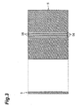
- Fig. 3 is a diagram showing the side face and front face of the slit plate 5.
- the slit plate 5 is made of a material which is difficult for X-rays to pass, and has three slits (pattern) 54 engraved in the center portion, with a residual area 56 formed between the slits 54.
- the X-ray tube adjusting apparatus 7 has a storage section 72, the acquisition section 74, a presentation section 76 and an operation section 78.
- the image (initial image) of the slit plate 5 imaged by the X-ray inspection apparatus 4 having the X-ray tube 1 in a state set at the time of shipment (at the time of shipment, the current value of the focus coil section 145 is set in such a way that the focal diameter becomes the optimal value under the initial tube voltage) as an X-ray source is stored in the storage section 72.
- the acquisition section 74 has a function of acquiring information, such as the image of the subject to be imaged which is sent by the communications section 24 of the X-ray tube controller 2, and the tube current value of the X-ray tube 1.
- the presentation section 76 has a function of presenting the initial image and an image representing the luminance on the initial image, and a test image and an image representing the luminance on the test image (details will be given later) simultaneously (in a comparable manner).
- the operation section 78 has a function of adjusting the current values of the alignment coil section 140 and the focus coil section 145 of the X-ray tube 1 via the telecommunications line.
- Fig. 5 is a flowchart illustrating procedures from replacement of the filament of the X-ray tube 1 to minimization of the focal diameter. Referring to Fig. 5, the procedures from replacement of the filament of the X-ray tube 1 to minimization of the focal diameter will be described.
- a user replaces the cathode (S501).
- the user degases the X-ray tube 1 by means of the vacuum pump 14 (S503) and warms up the X-ray tube 1 (S505).
- the position of the replaced filament 110 or target 150 of the X-ray tube 1 may be shifted, shifting the beam axis of the electron beam, which reduces the tube current as a consequence.
- the X-ray tube adjusting apparatus 7 automatically adjusts the position of the beam axis of the electron beam by changing the current value of the alignment coil section 140 in such a way as to maximize the tube current of the X-ray tube 1.
- a customer engineer checks if the positional alignment of the beam axis of the electron beam has been performed appropriately from the intensity of the X-rays detected by the image imaging device 3 (S507).
- the focal point of the electron beam may become wider, so that the focal diameter is minimized by the following process.
- the user of the X-ray inspection apparatus 4 sets the slit plate 5 at the same position as that where the initial image was imaged, and images it (S509).
- the image of the slit plate 5 (test image) acquired here is transmitted to the acquisition section 74 of the X-ray tube adjusting apparatus 7 by the communications section 24 of the X-ray tube controller 2.
- the presentation section 76 presents the initial image stored in the storage section 72 and an image representing the luminance on the initial image, and the test image and an image representing the luminance on the test image simultaneously (in a comparable manner) (S511).
- Fig. 4A shows the initial image and the image representing the luminance on the initial image presented by the presentation section 76.
- Fig. 4B shows the test image and the image representing the luminance on the test image.
- a portion a 1 indicates the initial image (the x direction being perpendicular to the lengthwise direction of the slit portion while the y direction is the lengthwise direction of the slit portion), and a portion a 2 represents the luminance on a line (line 4a) passing the center of the initial image and parallel to the x direction.
- a slit portion 764a equivalent to the slits 54 and a residual area portion (peripheral portion) 766a equivalent to the residual area 56 appear in the center portion of the initial image.
- a high luminance portion corresponding to the slit portion 764a and a low luminance portion equivalent to the residual area portion 766a appear in the center portion of the portion a 2 .
- a portion b 1 indicates the test image and a portion b 2 represents the luminance on a line (line 4b) passing the center of the test image and parallel to the x direction. While the images that appear at the portion b 1 and the portion b 2 are similar to images that appear at the portion a 1 and the portion a 2 , the contrast between the slit portion and the residual area becomes lower than the one that appears at the portion a 1 and the portion a 2 .
- a difference ⁇ b between the highest luminance corresponding to the slit portion 764b in the portion b 2 and a low luminance corresponding to the residual area portion 766b becomes smaller than a difference ⁇ a between the highest luminance corresponding to the slit portion 764a in the portion a 2 and a low luminance corresponding to the residual area portion 766a.
- the focal point of the electron beam in the X-ray tube 1 is widened at the time the initial image is imaged, a penumbra is produced around the bright portion. Accordingly, the contours of the slit portion 764b (bright portion) and the residual area portion 766b (dark portion) becomes unclear, so that the luminance at the slit portion 764b becomes relatively low and the luminance at the residual area portion 766b becomes relatively high.
- the contrast between the slit portion 764a and the residual area portion 766a on the initial image can be compared with the contrast between the slit portion 764b and the residual area portion 766b on the test image, so that it is possible to know from the difference between both contrasts how much the focal point at the time of adjusting the focal diameter (when the test image is imaged) is widened as compared with the focal point at the time of shipment of the X-ray tube 1 (when the current value of the focus coil section 145 is set in such a way that the focal diameter becomes the optimal value under the initial tube voltage). Further, it is possible to compute the current value of the focus coil section 145 to optimize the focal diameter from the comparison of the contrasts, i.e., from the difference between ⁇ a and ⁇ b, thus ensuring auto focus
- the operation section 78 adjusts the current value of the focus coil section 145 in such a way as to be the current value obtained in the above scheme for setting the focal diameter to the optimal value (S513).
- the focal point of the electron beam at the target 150 may also become wide when the tube voltage of the X-ray tube 1 is changed.
- the current value of the focus coil section 145 for adjustment to the optimal focal diameter can be known by comparing the contrast between the slit portion 764a and the residual area portion 766a on the initial image with the contrast between the slit portion 764b and the residual area portion 766b on the test image. It is to be noted, however, that as the tube voltage is changed, the intensity of X-rays to be irradiated is changed, so that it is necessary to consider its influence on the contrast between the slit portion 764b and the residual area portion 766b on the test image.
- the presentation section 76 of the X-ray tube adjusting apparatus 7 presents the contrast between the slit portion 764a and the residual area portion 766a on the initial image and the contrast between the slit portion 764b and the residual area portion 766b on the test image in a comparable manner
- a customer engineer can easily know, from information presented by the presentation section 76, how much the focal point is widened from the focal point restricted to the optimal level, and further know the current value of the focus coil section 145 that should be adjusted to achieve the optimal focal diameter, without going over to the place of the user.
- the customer engineer can remotely adjust the current value of the focus coil section 145 by using the operation section 78 the X-ray tube adjusting apparatus 7 without going over to the place of the user. As a result, the focus coil section 145 can be adjusted with less labor.
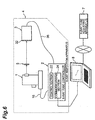
- Fig. 6 is a diagram for explaining an X-ray tube adjusting system according to the second embodiment.
- a customer engineer goes over to the installation site of the X-ray tube 1 and performs a process from replacement of the filament to focus adjustment.
- the maintenance manager receives a user's request of changing the filament
- a customer engineer carrying a notebook personal computer 8 goes over to the installation site of the X-ray tube 1.
- the customer engineer connects the notebook personal computer 8 to the X-ray tube adjusting apparatus 7, and sends identification information of the X-ray tube 1.
- the X-ray tube adjusting apparatus 7 acquires the initial image stored in association with the identification information of the X-ray tube 1 from the storage section 72 and downloads it to the notebook personal computer 8. Subsequently, the customer engineer connects the notebook personal computer 8 to the X-ray tube controller 2. The customer engineer shows the initial image and the test image and luminance information of both on the screen of the notebook personal computer 8, and performs processes similar to the S501 to S507.
- the X-ray tube adjusting apparatus, the X-ray tube adjusting system and the X-ray tube adjusting method according to the invention can be adapted for adjustment of, for example, medical X-ray generating equipment.
Landscapes
- Health & Medical Sciences (AREA)
- General Health & Medical Sciences (AREA)
- Toxicology (AREA)
- X-Ray Techniques (AREA)
- Analysing Materials By The Use Of Radiation (AREA)
Abstract
An initial image (the image of a slit plate 5
imaged when adjusted to an optimal focal diameter) is
stored in a storage section 72 of an X-ray tube
adjusting apparatus 7. An acquisition section 74
acquires a test image (the image of the slit plate 5
imaged at the time of adjusting the focal diameter). A
presentation section 76 presents the initial image and
an image representing the luminance on the initial
image (showing a contrast Δa between a slit portion
764a and a residual area portion 766a in the initial
image) and the test image and an image representing the
luminance on the test image (showing a contrast Δb
between a slit portion 764b and a residual area portion
766b in the initial image) simultaneously (in a
comparable manner).
Description
The present invention relates to an X-ray tube
adjusting apparatus, an X-ray tube adjusting system and
an X-ray tube adjusting method.
If the focal point when an electron beam in an X-ray
tube which is an X-ray generating source hits a
target is not restricted to an appropriate level at the
time of performing nondestructive inspection using an
X-ray inspection apparatus, a penumbra is formed in a
an imaging area, blurring the image. Even if the focus
lens in the X-ray tube (open tube) is initially
adjusted so that the focal point is restricted to an
appropriate level, the focal point may become wider as
the position of the filament or the target is deviated
at the time the filament or the target is replaced.
The focal point may also become wider when the tube
voltage to be applied to the target of the X-ray tube
is changed. As a measure in such a case,
conventionally, a customer engineer has adjusted the
focus lens in such a way that an image appearing on the
monitor of the X-ray inspection apparatus becomes
absolutely clear.
However, the conventional X-ray tube adjusting
method (focus lens adjusting method) had a problem that
it was difficult to optimally adjust the focus lens.
The invention has been made to overcome the
problem, and aims at providing an X-ray tube adjusting
apparatus, an X-ray tube adjusting system and an X-ray
tube adjusting method which facilitate optimal
adjustment of the focus lens.
To achieve the object, an X-ray tube adjusting
apparatus according to the invention is an X-ray tube
adjusting apparatus which remotely adjusts an X-ray
tube, comprising: storage means which stores,
beforehand, an initial image of a subject to be imaged
engraved with a given pattern, the initial image having
been imaged by an X-ray inspection apparatus having the
X-ray tube with a focal diameter of an electron beam at
a target of the X-ray tube adjusted so as to be a
predetermined value and an imaging device; acquisition
means which acquires a test image of the subject to be
imaged that is imaged at a time the X-ray inspection
apparatus adjusts the focal diameter via a
telecommunications line; and presentation means which
presents the initial image stored in the storage means
and the test image acquired by the acquisition means in
a comparable manner.
According to the X-ray tube adjusting apparatus
of the invention, an initial image stored in the
storage means (the image of a subject to be imaged,
which is imaged in a state where the focal diameter of
an electron beam at a target of the X-ray tube is
adjusted so as to be a predetermined value) and a test
image acquired by the acquisition means via a
telecommunications line (the image of the subject to be
imaged, which is imaged at the time of adjusting the
focal diameter) are presented in a comparable manner by
the presentation means. Therefore, it is possible to
know how much wider the focal point at the time of
adjusting the focal diameter (when the test image is
imaged) is as compared with the focal point in the
adjusted state from the difference in contrast between
pattern portions and their peripheral portions of both
images presented by the presentation means, and it is
further possible to know the adjustment value of the
focus lens to set the focal diameter to the
predetermined value. As a result, optimal adjustment
of the focus lens becomes easy.
It is preferable that the X-ray tube adjusting
apparatus according to the invention should include
operation means that manipulates a focus lens, which
adjusts a beam diameter of the electron beam in the X-ray
tube, via the telecommunications line.
The inclusion of the operation means that
manipulates the focus lens via the telecommunications
line can remotely operate the focus lens without a
customer engineer going to the site of the X-ray tube.
To achieve the object, an X-ray tube adjusting
system according to the invention is an X-ray tube
adjusting system which remotely adjusts an X-ray tube,
comprising: an X-ray inspection apparatus having an X-ray
tube and an imaging device; and an X-ray tube
adjusting apparatus having storage means which stores,
beforehand, an initial image of a subject to be imaged
engraved with a given pattern, the initial image having
been imaged by the X-ray inspection apparatus with a
focal diameter of an electron beam at a target of the
X-ray tube adjusted so as to be a predetermined value,
acquisition means which acquires a test image of the
subject to be imaged that is imaged at a time the X-ray
inspection apparatus adjusts the focal diameter via a
telecommunications line, and presentation means which
presents the initial image stored in the storage means
and the test image acquired by the acquisition means in
a comparable manner, and characterized in that the X-ray
inspection apparatus and the X-ray tube adjusting
apparatus are connected together via a
telecommunications line.
According to the X-ray tube adjusting system of
the invention, an initial image stored in the storage
means (the image of a subject to be imaged, which is
imaged in a state where the focal diameter of an
electron beam at a target of the X-ray tube is adjusted
so as to be a predetermined value) and a test image
acquired by the acquisition means via a
telecommunications line (the image of the subject to be
imaged, which is imaged at the time of adjusting the
focal diameter) are presented in a comparable manner by
the presentation means. Therefore, it is possible to
know how much wider the focal point at the time of
adjusting the focal diameter (when the test image is
imaged) is as compared with the focal point in the
adjusted state from the difference in contrast between
pattern portions and their peripheral portions of both
images presented by the presentation means, and it is
further possible to know the adjustment value of the
focus lens to set the focal diameter to the
predetermined value. As a result, optimal adjustment
of the focus lens becomes easy.
To achieve the object, an X-ray tube adjusting
method according to the invention is an X-ray tube
adjusting method for remotely adjusting an X-ray tube,
wherein an initial image of a subject to be imaged
engraved with a given pattern is stored in storage
means beforehand, the initial image having been imaged
by an X-ray inspection apparatus having the X-ray tube
with a focal diameter of an electron beam at a target
of the X-ray tube adjusted so as to be a predetermined
value and an imaging device, and comprising: an
acquisition step at which acquisition means acquires a
test image of the subject to be imaged that is imaged
at a time the X-ray inspection apparatus adjusts the
focal diameter; and a presentation step at which
presentation means presents the initial image stored in
the storage means and the test image acquired by the
acquisition means in a comparable manner.
Another aspect of the X-ray tube adjusting method
according to the invention is an X-ray tube adjusting
method, wherein an initial image of a subject to be
imaged engraved with a given pattern is stored in
storage means beforehand in association with
identification information of the X-ray tube, the
initial image having been imaged by an X-ray inspection
apparatus having the X-ray tube with a focal diameter
of an electron beam at a target of the X-ray tube
adjusted so as to be a predetermined value and an
imaging device, and comprising: an imaging step at
which the X-ray inspection apparatus images a test
image of the subject to be imaged at a time parts of
the X-ray tube are replaced; and a presentation step at
which the initial image associated with the
identification information of the X-ray tube is
acquired from the storage means and presented in such a
manner as to be comparable with the test image.
According to the X-ray tube adjusting method of
the invention, an initial image stored in the storage
means (the image of a subject to be imaged, which is
imaged in a state where the focal diameter of an
electron beam at a target of the X-ray tube is adjusted
so as to be a predetermined value) and a test image
(the image of the subject to be imaged, which is imaged
at the time of adjusting the focal diameter) are
presented in a comparable manner at the presentation
step. Therefore, it is possible to know how much wider
the focal point at the time of adjusting the focal
diameter (when the test image is imaged) is as compared
with the focal point in the adjusted state from the
difference in contrast between pattern portions and
their peripheral portions of both images presented at
the presentation step, and it is further possible to
know the adjustment value of the focus lens to set the
focal diameter to the predetermined value. As a result,
optimal adjustment of the focus lens becomes easy.
It is preferable that the X-ray tube adjusting
method should include an operation step at which
operation means manipulates a focus lens, which adjusts
a beam diameter of the electron beam in said X-ray tube,
via the telecommunications line.
The inclusion of the operation step that
manipulates the focus lens via the telecommunications
line can remotely manipulate the focus lens without a
customer engineer going to the site of the X-ray tube.
Preferred embodiments of an X-ray tube adjusting
apparatus, an X-ray tube adjusting system and an X-ray
tube adjusting method according to the invention will
be described in detail below with reference to the
accompanying drawings.
First, the structure and operation of an X-ray
tube 1 which is adjusted by an X-ray tube adjusting
system according to the embodiment will be described.
Fig. 1 is an exemplary diagram (cross-sectional view)
showing the structure of the X-ray tube 1. As shown in
Fig. 1, the X-ray tube 1 is sealed by the outer casing
comprised of a metal enclosure 11, a stem 12 and a
beryllium window 13. The X-ray tube 1 has a vacuum
pump 14, and a gas inside the outer casing is degassed
by the vacuum pump 14 before activation of the X-ray
tube 1.
The X-ray tube 1 has, inside of the outer casing,
a filament 110 which emits thermions when energized, a
first grid electrode 120 which pushes the thermions
back toward the filament side and a second grid
electrode 130, which pulls the thermions toward the
target side, a alignment coil section 140 which adjusts
the position of the beam axis of an electron beam, a
focus coil section (focus lens) 145, and a tungsten
target 150 which generates X-rays when hit by the
thermions. The first grid electrode 120, the second
grid electrode 130, the alignment coil section 140 and
the focus coil section 145 are arranged in that order
from the filament 110 toward the target 150, and the
first grid electrode 120 and the second grid electrode
130 respectively have an opening 120a and an opening
130a in their centers for passing the thermions.
The X-ray tube 1 has a power supply 15 including
a high-voltage generating circuit for applying a
positive high voltage to the target 150.
The X-ray tube 1 is controlled by an X-ray tube
controller 2 connected to the X-ray tube 1 by a control
cable 16.
When applied with a predetermined voltage and
energized, the filament 110 emits thermions. When the
voltage which is applied to the first grid electrode
120 rises from the cutoff voltage to an operation
voltage, the thermions emitted from the filament 110
are pulled to the second grid electrode 130, which has
a higher potential than the filament 110 does, and thus
pass through the opening 120a of the first grid
electrode 120. Further, the thermions pass through the
opening 130a of the second grid electrode 130 while
being accelerated by the tube voltage applied to the
target 150, and becomes an electron beam directing
toward the target 150 applied with the positive high
voltage.
At the time of passing the magnetic field formed
in a direction perpendicular to the traveling direction
of the electron beam by the alignment coil section 140,
the position of the beam axis of the electron beam is
adjusted by electromagnetic deflection in such a way as
to pass the center of the X-ray tube 1. Further, the
beam diameter of the electron beam is contracted by the
focus coil section 145. When the electron beam which
is converged by the focus coil section 145 hits the
target 150, the target 150 generates X-rays. The X-rays
pass through the beryllium window 13 and exit the
X-ray tube 1. The intensity of the X-rays that are
generated by the target 150 is determined by the level
of the tube voltage and the magnitude of the tube
current. The focal diameter when the electron beam
hits the target 150 is changed by the intensity of the
magnetic field of the focus coil section 145 (i.e., the
magnitude of the current flowing in the focus coil
section 145) and the level of the tube voltage.
Next, the functional structure of the X-ray tube
adjusting system according to the embodiment will be
described. Fig. 2 is a diagram for explaining the X-ray
tube adjusting system according to the first
embodiment. As shown in Fig. 2, the X-ray tube
adjusting system according to the embodiment has an X-ray
inspection apparatus 4 comprising the X-ray tube 1,
the X-ray tube controller 2 and an imaging device 3,
and an X-ray tube adjusting apparatus 7. The X-ray
inspection apparatus 4 is set at the place of a user
while the X-ray tube adjusting apparatus 7 is set at
the place of a maintenance manager for the X-ray tube,
and both are connected via a telecommunications line
such as the Internet.
The image imaging device 3 has an imaging area 32,
and images an image of a subject to be imaged which
appears on the imaging area 32 as X-rays generated by
the X-ray tube 1 are irradiated. The image imaging
device 3 is connected to the X-ray tube controller 2 by
a cable 36.
The X-ray tube controller 2 has a control section
22, and a communications section 24. The control
section 22 has a main power supply switch, an X-ray
irradiation switch, a tube voltage adjusting section, a
tube current adjusting section, etc., and has a
function of energizing the filament in the X-ray tube 1,
switching of the voltage to be applied to the first
grid electrode (cutoff voltage, operation voltage), and
controlling adjustment or so of the tube voltage and
the tube current. The communications section 24 has a
function of sending the image of the subject to be
imaged, picked up by the image imaging device 3, to an
acquisition section 74 of the X-ray tube adjusting
apparatus 7, receiving a control command from an
operation section 78 of the X-ray tube adjusting
apparatus 7 and transferring it to the control section
22.
In the embodiment, a slit plate 5 is set as a
subject to be imaged in the X-ray inspection apparatus
4. Fig. 3 is a diagram showing the side face and front
face of the slit plate 5. The slit plate 5 is made of
a material which is difficult for X-rays to pass, and
has three slits (pattern) 54 engraved in the center
portion, with a residual area 56 formed between the
slits 54.
The X-ray tube adjusting apparatus 7 has a
storage section 72, the acquisition section 74, a
presentation section 76 and an operation section 78.
The image (initial image) of the slit plate 5 imaged by
the X-ray inspection apparatus 4 having the X-ray tube
1 in a state set at the time of shipment (at the time
of shipment, the current value of the focus coil
section 145 is set in such a way that the focal
diameter becomes the optimal value under the initial
tube voltage) as an X-ray source is stored in the
storage section 72. The acquisition section 74 has a
function of acquiring information, such as the image of
the subject to be imaged which is sent by the
communications section 24 of the X-ray tube controller
2, and the tube current value of the X-ray tube 1. The
presentation section 76 has a function of presenting
the initial image and an image representing the
luminance on the initial image, and a test image and an
image representing the luminance on the test image
(details will be given later) simultaneously (in a
comparable manner). The operation section 78 has a
function of adjusting the current values of the
alignment coil section 140 and the focus coil section
145 of the X-ray tube 1 via the telecommunications line.
Fig. 5 is a flowchart illustrating procedures
from replacement of the filament of the X-ray tube 1 to
minimization of the focal diameter. Referring to Fig.
5, the procedures from replacement of the filament of
the X-ray tube 1 to minimization of the focal diameter
will be described. First, a user replaces the cathode
(S501). When the user uses the X-ray tube 1 for the
first time after replacement of the cathode, the user
degases the X-ray tube 1 by means of the vacuum pump 14
(S503) and warms up the X-ray tube 1 (S505).
When the filament 110 or the target 150 of the X-ray
tube 1 is replaced, the position of the replaced
filament 110 or target 150 may be shifted, shifting the
beam axis of the electron beam, which reduces the tube
current as a consequence. The X-ray tube adjusting
apparatus 7 automatically adjusts the position of the
beam axis of the electron beam by changing the current
value of the alignment coil section 140 in such a way
as to maximize the tube current of the X-ray tube 1. A
customer engineer checks if the positional alignment of
the beam axis of the electron beam has been performed
appropriately from the intensity of the X-rays detected
by the image imaging device 3 (S507).
As the position of the replaced filament 110 or
target 150 may be shifted, the focal point of the
electron beam may become wider, so that the focal
diameter is minimized by the following process. The
user of the X-ray inspection apparatus 4 sets the slit
plate 5 at the same position as that where the initial
image was imaged, and images it (S509). The image of
the slit plate 5 (test image) acquired here is
transmitted to the acquisition section 74 of the X-ray
tube adjusting apparatus 7 by the communications
section 24 of the X-ray tube controller 2.
When the acquisition section 74 of the X-ray tube
adjusting apparatus 7 acquires the test image, the
presentation section 76 presents the initial image
stored in the storage section 72 and an image
representing the luminance on the initial image, and
the test image and an image representing the luminance
on the test image simultaneously (in a comparable
manner) (S511). Fig. 4A shows the initial image and
the image representing the luminance on the initial
image presented by the presentation section 76. Fig.
4B shows the test image and the image representing the
luminance on the test image. In Fig. 4A, a portion a1
indicates the initial image (the x direction being
perpendicular to the lengthwise direction of the slit
portion while the y direction is the lengthwise
direction of the slit portion), and a portion a2
represents the luminance on a line (line 4a) passing
the center of the initial image and parallel to the x
direction. A slit portion 764a equivalent to the slits
54 and a residual area portion (peripheral portion)
766a equivalent to the residual area 56 appear in the
center portion of the initial image. A high luminance
portion corresponding to the slit portion 764a and a
low luminance portion equivalent to the residual area
portion 766a appear in the center portion of the
portion a2.
In Fig. 4B, a portion b1 indicates the test image
and a portion b2 represents the luminance on a line
(line 4b) passing the center of the test image and
parallel to the x direction. While the images that
appear at the portion b1 and the portion b2 are similar
to images that appear at the portion a1 and the portion
a2, the contrast between the slit portion and the
residual area becomes lower than the one that appears
at the portion a1 and the portion a2. That is, a
difference Δb between the highest luminance
corresponding to the slit portion 764b in the portion
b2 and a low luminance corresponding to the residual
area portion 766b becomes smaller than a difference Δa
between the highest luminance corresponding to the slit
portion 764a in the portion a2 and a low luminance
corresponding to the residual area portion 766a. As
the focal point of the electron beam in the X-ray tube
1 is restricted to the optimal level at the time the
initial image is imaged, the contours of the slit
portion 764a (bright portion) and the residual area
portion 766a (dark portion) becomes clear. By way of
contrast, the focal point of the electron beam in the
X-ray tube 1 is widened at the time the initial image
is imaged, a penumbra is produced around the bright
portion. Accordingly, the contours of the slit portion
764b (bright portion) and the residual area portion
766b (dark portion) becomes unclear, so that the
luminance at the slit portion 764b becomes relatively
low and the luminance at the residual area portion 766b
becomes relatively high.
As the presentation section 76 in the X-ray tube
adjusting apparatus 7 presents the initial image and
the image representing the luminance on the initial
image, and the test image and the image representing
the luminance on the test image simultaneously (in a
comparable manner), the contrast between the slit
portion 764a and the residual area portion 766a on the
initial image can be compared with the contrast between
the slit portion 764b and the residual area portion
766b on the test image, so that it is possible to know
from the difference between both contrasts how much the
focal point at the time of adjusting the focal diameter
(when the test image is imaged) is widened as compared
with the focal point at the time of shipment of the X-ray
tube 1 (when the current value of the focus coil
section 145 is set in such a way that the focal
diameter becomes the optimal value under the initial
tube voltage). Further, it is possible to compute the
current value of the focus coil section 145 to optimize
the focal diameter from the comparison of the contrasts,
i.e., from the difference between Δa and Δb, thus
ensuring auto focus adjustment.
The operation section 78 adjusts the current
value of the focus coil section 145 in such a way as to
be the current value obtained in the above scheme for
setting the focal diameter to the optimal value (S513).
The focal point of the electron beam at the
target 150 may also become wide when the tube voltage
of the X-ray tube 1 is changed. In this case too, the
current value of the focus coil section 145 for
adjustment to the optimal focal diameter can be known
by comparing the contrast between the slit portion 764a
and the residual area portion 766a on the initial image
with the contrast between the slit portion 764b and the
residual area portion 766b on the test image. It is to
be noted, however, that as the tube voltage is changed,
the intensity of X-rays to be irradiated is changed, so
that it is necessary to consider its influence on the
contrast between the slit portion 764b and the residual
area portion 766b on the test image.
Next the effect of the X-ray tube adjusting
system according to the embodiment will be described.
As mentioned above, the presentation section 76 of the
X-ray tube adjusting apparatus 7 presents the contrast
between the slit portion 764a and the residual area
portion 766a on the initial image and the contrast
between the slit portion 764b and the residual area
portion 766b on the test image in a comparable manner,
a customer engineer can easily know, from information
presented by the presentation section 76, how much the
focal point is widened from the focal point restricted
to the optimal level, and further know the current
value of the focus coil section 145 that should be
adjusted to achieve the optimal focal diameter, without
going over to the place of the user. Also, the
customer engineer can remotely adjust the current value
of the focus coil section 145 by using the operation
section 78 the X-ray tube adjusting apparatus 7 without
going over to the place of the user. As a result, the
focus coil section 145 can be adjusted with less labor.
Fig. 6 is a diagram for explaining an X-ray tube
adjusting system according to the second embodiment.
In the second embodiment, a customer engineer goes over
to the installation site of the X-ray tube 1 and
performs a process from replacement of the filament to
focus adjustment. When the maintenance manager
receives a user's request of changing the filament, a
customer engineer carrying a notebook personal computer
8 goes over to the installation site of the X-ray tube
1. After performing processes similar to the S501 to
S507, the customer engineer connects the notebook
personal computer 8 to the X-ray tube adjusting
apparatus 7, and sends identification information of
the X-ray tube 1. The X-ray tube adjusting apparatus 7
acquires the initial image stored in association with
the identification information of the X-ray tube 1 from
the storage section 72 and downloads it to the notebook
personal computer 8. Subsequently, the customer
engineer connects the notebook personal computer 8 to
the X-ray tube controller 2. The customer engineer
shows the initial image and the test image and
luminance information of both on the screen of the
notebook personal computer 8, and performs processes
similar to the S501 to S507.
The X-ray tube adjusting apparatus, the X-ray
tube adjusting system and the X-ray tube adjusting
method according to the invention can be adapted for
adjustment of, for example, medical X-ray generating
equipment.
Claims (7)
- An X-ray tube adjusting apparatus which remotely adjusts an X-ray tube, comprising:storage means which stores, beforehand, an initial image of a subject to be imaged engraved with a given pattern, said initial image having been imaged by an X-ray inspection apparatus having said X-ray tube with a focal diameter of an electron beam at a target of said X-ray tube adjusted so as to be a predetermined value and an imaging device;acquisition means which acquires a test image of said subject to be imaged that is imaged at a time said X-ray inspection apparatus adjusts the focal diameter via a telecommunications line; andpresentation means which presents said initial image stored in said storage means and said test image acquired by said acquisition means in a comparable manner.
- The X-ray tube adjusting apparatus according to Claim 1, including operation means that manipulates a focus lens, which adjusts a beam diameter of the electron beam in said X-ray tube, via a telecommunications line.
- An X-ray tube adjusting system which remotely adjusts an X-ray tube, comprising:and characterized in that said X-ray inspection apparatus and said X-ray tube adjusting apparatus are connected together via a telecommunications line.an X-ray inspection apparatus having an X-ray tube and an imaging device; andan X-ray tube adjusting apparatus having
storage means which stores, beforehand, an initial image of a subject to be imaged engraved with a given pattern, said initial image having been imaged by said X-ray inspection apparatus with a focal diameter of an electron beam at a target of said X-ray tube adjusted so as to be a predetermined value,
acquisition means which acquires a test image of said subject to be imaged that is imaged at a time said X-ray inspection apparatus adjusts the focal diameter via a telecommunications line, and
presentation means which presents said initial image stored in said storage means and said test image acquired by said acquisition means in a comparable manner, - An X-ray tube adjusting method for remotely adjusting an X-ray tube,
wherein an initial image of a subject to be imaged engraved with a given pattern is stored in storage means beforehand, said initial image having been imaged by an X-ray inspection apparatus having said X-ray tube with a focal diameter of an electron beam at a target of said X-ray tube adjusted so as to be a predetermined value and an imaging device, and comprising:an acquisition step at which acquisition means acquires a test image of said subject to be imaged that is imaged at a time said X-ray inspection apparatus adjusts the focal diameter; anda presentation step at which presentation means presents said initial image stored in said storage means and said test image acquired by said acquisition means in a comparable manner. - The X-ray tube adjusting method according to Claim 4, comprising an operation step at which operation means manipulates a focus lens, which adjusts a beam diameter of the electron beam in said X-ray tube, via the telecommunications line.
- An X-ray tube adjusting method,
wherein an initial image of a subject to be imaged engraved with a given pattern is stored in storage means beforehand in association with identification information of said X-ray tube, said initial image having been imaged by an X-ray inspection apparatus having said X-ray tube with a focal diameter of an electron beam at a target of said X-ray tube adjusted so as to be a predetermined value and an imaging device, and comprising:an imaging step at which said X-ray inspection apparatus images a test image of said subject to be imaged at a time parts of said X-ray tube are replaced; anda presentation step at which the initial image associated with the identification information of said X-ray tube is acquired from said storage means and presented in such a manner as to be comparable with said test image. - The X-ray tube adjusting method according to Claim 6, further comprising:an alignment adjusting step at which a position of a beam axis of the electron beam in said X-ray tube is adjusted;a set step at which, following said alignment adjusting step and prior to said imaging step, said subject to be imaged is placed at a same position as that when said initial image was imaged; anda focus adjusting step at which referring to the images presented at said presentation step, a focus lens of said X-ray tube is adjusted in such a way that a focal diameter of the electron beam at a target of said X-ray tube becomes said desired state.
Applications Claiming Priority (3)
| Application Number | Priority Date | Filing Date | Title |
|---|---|---|---|
| JP2002103917 | 2002-04-05 | ||
| JP2002103917 | 2002-04-05 | ||
| PCT/JP2003/004356 WO2003086027A1 (en) | 2002-04-05 | 2003-04-04 | X-ray tube adjustment apparatus, x-ray tube adjustment system, and x-ray tube adjustment method |
Publications (2)
| Publication Number | Publication Date |
|---|---|
| EP1501339A1 true EP1501339A1 (en) | 2005-01-26 |
| EP1501339A4 EP1501339A4 (en) | 2009-11-04 |
Family
ID=28786320
Family Applications (1)
| Application Number | Title | Priority Date | Filing Date |
|---|---|---|---|
| EP03745699A Withdrawn EP1501339A4 (en) | 2002-04-05 | 2003-04-04 | X-ray tube adjustment apparatus, x-ray tube adjustment system, and x-ray tube adjustment method |
Country Status (8)
| Country | Link |
|---|---|
| US (1) | US7212610B2 (en) |
| EP (1) | EP1501339A4 (en) |
| JP (1) | JP4308673B2 (en) |
| KR (1) | KR20040098041A (en) |
| CN (1) | CN100355323C (en) |
| AU (1) | AU2003236267A1 (en) |
| TW (1) | TWI261485B (en) |
| WO (1) | WO2003086027A1 (en) |
Cited By (3)
| Publication number | Priority date | Publication date | Assignee | Title |
|---|---|---|---|---|
| WO2008006569A2 (en) | 2006-07-11 | 2008-01-17 | Carl Zeiss Industrielle Messtechnik Gmbh | Arrangement for producing electromagnetic radiation and method for operating said arrangement |
| US8831179B2 (en) | 2011-04-21 | 2014-09-09 | Carl Zeiss X-ray Microscopy, Inc. | X-ray source with selective beam repositioning |
| EP3089192A1 (en) * | 2010-12-22 | 2016-11-02 | Excillum AB | Focusing an electron beam in an x-ray source |
Families Citing this family (5)
| Publication number | Priority date | Publication date | Assignee | Title |
|---|---|---|---|---|
| JP4755005B2 (en) * | 2005-10-07 | 2011-08-24 | 浜松ホトニクス株式会社 | X-ray tube and nondestructive inspection equipment |
| DE102007043820B4 (en) * | 2007-09-13 | 2020-06-04 | Carl Zeiss Industrielle Messtechnik Gmbh | Method for determining a correction value of a brake spot position of an X-ray source of a measuring arrangement and a measuring arrangement for generating radiographic images |
| JP6134130B2 (en) * | 2012-01-23 | 2017-05-24 | ギガフォトン株式会社 | Target generation condition determination apparatus and target generation system |
| JP6441015B2 (en) * | 2014-10-06 | 2018-12-19 | キヤノンメディカルシステムズ株式会社 | X-ray diagnostic apparatus and X-ray tube control method |
| CN115811822B (en) * | 2022-11-24 | 2026-03-17 | 上海联影医疗科技股份有限公司 | A method, apparatus, and X-ray imaging system for controlling X-ray imaging voltage. |
Family Cites Families (20)
| Publication number | Priority date | Publication date | Assignee | Title |
|---|---|---|---|---|
| SU458899A1 (en) * | 1973-03-22 | 1975-01-30 | Предприятие П/Я М-5659 | X-ray tube |
| JPS61218100A (en) | 1985-03-22 | 1986-09-27 | Toshiba Corp | X-ray tube and x-ray photographing device utilizing same |
| DE3545348A1 (en) * | 1985-12-20 | 1987-06-25 | Siemens Ag | X-RAY DIAGNOSTIC DEVICE WITH LOCAL FREQUENCY HIGH-PASS FILTERING |
| SU1450144A1 (en) * | 1987-07-29 | 1989-01-07 | Всесоюзный научно-исследовательский институт по строительству магистральных трубопроводов | Method of measuring the effective size of focus of x-ray source |
| US4937270A (en) * | 1987-09-18 | 1990-06-26 | Genzyme Corporation | Water insoluble derivatives of hyaluronic acid |
| JPH05259249A (en) * | 1992-03-16 | 1993-10-08 | Fujitsu Ltd | Flip chip inspection method and device |
| SE502298C2 (en) * | 1993-11-25 | 1995-10-02 | Rti Electronics Ab | Method and apparatus for imaging or measuring a radiation source in one dimension |
| JP2927206B2 (en) | 1995-04-27 | 1999-07-28 | 株式会社島津製作所 | X-ray diagnostic equipment |
| JP3465424B2 (en) * | 1995-06-30 | 2003-11-10 | 株式会社島津製作所 | X-ray equipment |
| JPH0971594A (en) | 1995-09-07 | 1997-03-18 | Mitsubishi Chem Corp | Process for producing fatty acid ester of sugar or sugar alcohol by enzymatic method |
| JP3919294B2 (en) | 1997-06-24 | 2007-05-23 | キヤノン株式会社 | Industrial equipment remote maintenance system and method |
| US5841835A (en) * | 1997-03-31 | 1998-11-24 | General Electric Company | Apparatus and method for automatic monitoring and assessment of image quality in x-ray systems |
| US6233349B1 (en) * | 1997-06-20 | 2001-05-15 | General Electric Company | Apparata and methods of analyzing the focal spots of X-ray tubes |
| DE19820243A1 (en) * | 1998-05-06 | 1999-11-11 | Siemens Ag | X=ray tube with variable sized X=ray focal spot and focus switching |
| JP2000210800A (en) | 1999-01-27 | 2000-08-02 | Komatsu Ltd | Industrial machine monitoring method and apparatus |
| JP2000245721A (en) | 1999-02-25 | 2000-09-12 | Konica Corp | Radiation imaging device |
| US6256372B1 (en) * | 1999-03-16 | 2001-07-03 | General Electric Company | Apparatus and methods for stereo radiography |
| JP4010101B2 (en) * | 1999-09-21 | 2007-11-21 | コニカミノルタホールディングス株式会社 | X-ray imaging device |
| JP3481186B2 (en) * | 2000-06-08 | 2003-12-22 | メディエックステック株式会社 | X-ray generator, X-ray inspection apparatus, and X-ray generation method |
| JP2002008572A (en) * | 2000-06-20 | 2002-01-11 | Shimadzu Corp | X-ray tube |
-
2003
- 2003-04-04 KR KR10-2004-7015704A patent/KR20040098041A/en not_active Ceased
- 2003-04-04 US US10/510,213 patent/US7212610B2/en not_active Expired - Fee Related
- 2003-04-04 EP EP03745699A patent/EP1501339A4/en not_active Withdrawn
- 2003-04-04 CN CNB038076993A patent/CN100355323C/en not_active Expired - Fee Related
- 2003-04-04 TW TW092107723A patent/TWI261485B/en not_active IP Right Cessation
- 2003-04-04 WO PCT/JP2003/004356 patent/WO2003086027A1/en not_active Ceased
- 2003-04-04 JP JP2003583067A patent/JP4308673B2/en not_active Expired - Fee Related
- 2003-04-04 AU AU2003236267A patent/AU2003236267A1/en not_active Abandoned
Cited By (9)
| Publication number | Priority date | Publication date | Assignee | Title |
|---|---|---|---|---|
| WO2008006569A2 (en) | 2006-07-11 | 2008-01-17 | Carl Zeiss Industrielle Messtechnik Gmbh | Arrangement for producing electromagnetic radiation and method for operating said arrangement |
| DE102006032607A1 (en) * | 2006-07-11 | 2008-01-17 | Carl Zeiss Industrielle Messtechnik Gmbh | Arrangement for generating electromagnetic radiation and method for operating the arrangement |
| WO2008006569A3 (en) * | 2006-07-11 | 2008-03-20 | Zeiss Ind Messtechnik Gmbh | Arrangement for producing electromagnetic radiation and method for operating said arrangement |
| DE102006032607B4 (en) * | 2006-07-11 | 2011-08-25 | Carl Zeiss Industrielle Messtechnik GmbH, 73447 | Arrangement for generating electromagnetic radiation and method for operating the arrangement |
| EP3089192A1 (en) * | 2010-12-22 | 2016-11-02 | Excillum AB | Focusing an electron beam in an x-ray source |
| US9947502B2 (en) | 2010-12-22 | 2018-04-17 | Excillum Ab | Aligning and focusing an electron beam in an X-ray source |
| US8831179B2 (en) | 2011-04-21 | 2014-09-09 | Carl Zeiss X-ray Microscopy, Inc. | X-ray source with selective beam repositioning |
| US8995622B2 (en) | 2011-04-21 | 2015-03-31 | Carl Zeiss X-ray Microscopy, Inc. | X-ray source with increased operating life |
| US9142382B2 (en) | 2011-04-21 | 2015-09-22 | Carl Zeiss X-ray Microscopy, Inc. | X-ray source with an immersion lens |
Also Published As
| Publication number | Publication date |
|---|---|
| EP1501339A4 (en) | 2009-11-04 |
| AU2003236267A1 (en) | 2003-10-20 |
| JPWO2003086027A1 (en) | 2005-08-18 |
| US7212610B2 (en) | 2007-05-01 |
| US20060067477A1 (en) | 2006-03-30 |
| TW200306135A (en) | 2003-11-01 |
| CN100355323C (en) | 2007-12-12 |
| WO2003086027A1 (en) | 2003-10-16 |
| TWI261485B (en) | 2006-09-01 |
| JP4308673B2 (en) | 2009-08-05 |
| KR20040098041A (en) | 2004-11-18 |
| CN1647589A (en) | 2005-07-27 |
Similar Documents
| Publication | Publication Date | Title |
|---|---|---|
| US8487534B2 (en) | Pierce gun and method of controlling thereof | |
| EP0949653B1 (en) | Electron beam apparatus | |
| US5528658A (en) | X-ray tube having an annular vacuum housing | |
| JP2789399B2 (en) | Scanning electron microscope and observation method thereof | |
| JP2002540581A (en) | Method and apparatus for extending the life of an x-ray target | |
| US3833811A (en) | Scanning electron microscope with improved means for focusing | |
| US7212610B2 (en) | X-ray tube adjustment apparatus, x-ray tube adjustment system, and x-ray tube adjustment method | |
| US20070051907A1 (en) | Device for generating X-ray or XUV radiation | |
| JP2002150987A (en) | Electron microscope and transmission electron image capturing method in electron microscope | |
| JP3153391B2 (en) | Focused ion beam equipment | |
| JP3376793B2 (en) | Scanning electron microscope | |
| JP2003151484A (en) | Scanning charged particle beam device | |
| JPH08255588A (en) | Scanning electron microscope and similar devices | |
| US4722097A (en) | X-ray diagnostics installation with spatial frequency high-pass filtering | |
| JP2001004559A (en) | X-ray inspection equipment | |
| JP2000208089A (en) | Electron microscope equipment | |
| JPH10334844A (en) | Scanning electron microscope | |
| JP2003004668A (en) | X-ray inspection equipment | |
| JP4728173B2 (en) | Method for adjusting electron beam axis of scanning electron microscope and scanning electron microscope | |
| JPH02267894A (en) | Focus compensation device for x-ray generator | |
| CN121601518A (en) | Method for regulating focal spot of X-ray tube, X-ray tube and medical equipment | |
| JPH11260308A (en) | Drawing equipment | |
| JPH07288096A (en) | Sample charge detection method and scanning electron microscope | |
| JPS6248344B2 (en) | ||
| JPS6332220B2 (en) |
Legal Events
| Date | Code | Title | Description |
|---|---|---|---|
| PUAI | Public reference made under article 153(3) epc to a published international application that has entered the european phase |
Free format text: ORIGINAL CODE: 0009012 |
|
| 17P | Request for examination filed |
Effective date: 20041029 |
|
| AK | Designated contracting states |
Kind code of ref document: A1 Designated state(s): AT BE BG CH CY CZ DE DK EE ES FI FR GB GR HU IE IT LI LU MC NL PT RO SE SI SK TR |
|
| AX | Request for extension of the european patent |
Extension state: AL LT LV MK |
|
| A4 | Supplementary search report drawn up and despatched |
Effective date: 20091006 |
|
| 17Q | First examination report despatched |
Effective date: 20091012 |
|
| STAA | Information on the status of an ep patent application or granted ep patent |
Free format text: STATUS: THE APPLICATION IS DEEMED TO BE WITHDRAWN |
|
| 18D | Application deemed to be withdrawn |
Effective date: 20100222 |