EP1500749A1 - Vorrichtung zum Filtern/Sieben einer mit Feststoffen beladenen Flüssigkeit und dazugehöriges Sieb-/Filterverfahren - Google Patents
Vorrichtung zum Filtern/Sieben einer mit Feststoffen beladenen Flüssigkeit und dazugehöriges Sieb-/Filterverfahren Download PDFInfo
- Publication number
- EP1500749A1 EP1500749A1 EP04102535A EP04102535A EP1500749A1 EP 1500749 A1 EP1500749 A1 EP 1500749A1 EP 04102535 A EP04102535 A EP 04102535A EP 04102535 A EP04102535 A EP 04102535A EP 1500749 A1 EP1500749 A1 EP 1500749A1
- Authority
- EP
- European Patent Office
- Prior art keywords
- rake
- filter screen
- bars
- teeth
- liquid
- Prior art date
- Legal status (The legal status is an assumption and is not a legal conclusion. Google has not performed a legal analysis and makes no representation as to the accuracy of the status listed.)
- Withdrawn
Links
- 238000001914 filtration Methods 0.000 title claims abstract description 18
- 238000000034 method Methods 0.000 title claims abstract description 9
- 239000007788 liquid Substances 0.000 title claims description 38
- 238000007873 sieving Methods 0.000 title claims description 19
- 238000004140 cleaning Methods 0.000 claims abstract description 45
- 239000002699 waste material Substances 0.000 claims abstract description 39
- 238000012216 screening Methods 0.000 claims abstract description 18
- 238000011144 upstream manufacturing Methods 0.000 claims description 16
- 238000011084 recovery Methods 0.000 claims description 4
- 230000000717 retained effect Effects 0.000 claims description 4
- 238000013459 approach Methods 0.000 claims description 3
- 230000008021 deposition Effects 0.000 claims 1
- 230000000149 penetrating effect Effects 0.000 claims 1
- 238000009991 scouring Methods 0.000 claims 1
- 238000006073 displacement reaction Methods 0.000 abstract description 2
- XLYOFNOQVPJJNP-UHFFFAOYSA-N water Substances O XLYOFNOQVPJJNP-UHFFFAOYSA-N 0.000 abstract description 2
- 238000010276 construction Methods 0.000 description 10
- 230000005484 gravity Effects 0.000 description 3
- 239000000463 material Substances 0.000 description 2
- 239000002184 metal Substances 0.000 description 2
- 238000005086 pumping Methods 0.000 description 2
- 239000002351 wastewater Substances 0.000 description 2
- 240000008042 Zea mays Species 0.000 description 1
- 230000001174 ascending effect Effects 0.000 description 1
- 239000010782 bulky waste Substances 0.000 description 1
- 210000000078 claw Anatomy 0.000 description 1
- 239000002131 composite material Substances 0.000 description 1
- 238000013461 design Methods 0.000 description 1
- 239000004744 fabric Substances 0.000 description 1
- 230000035515 penetration Effects 0.000 description 1
- 238000013519 translation Methods 0.000 description 1
- 238000005406 washing Methods 0.000 description 1
Images


Classifications
-
- E—FIXED CONSTRUCTIONS
- E02—HYDRAULIC ENGINEERING; FOUNDATIONS; SOIL SHIFTING
- E02B—HYDRAULIC ENGINEERING
- E02B8/00—Details of barrages or weirs ; Energy dissipating devices carried by lock or dry-dock gates
- E02B8/02—Sediment base gates; Sand sluices; Structures for retaining arresting waterborne material
- E02B8/023—Arresting devices for waterborne materials
- E02B8/026—Cleaning devices
-
- B—PERFORMING OPERATIONS; TRANSPORTING
- B01—PHYSICAL OR CHEMICAL PROCESSES OR APPARATUS IN GENERAL
- B01D—SEPARATION
- B01D29/00—Filters with filtering elements stationary during filtration, e.g. pressure or suction filters, not covered by groups B01D24/00 - B01D27/00; Filtering elements therefor
- B01D29/01—Filters with filtering elements stationary during filtration, e.g. pressure or suction filters, not covered by groups B01D24/00 - B01D27/00; Filtering elements therefor with flat filtering elements
-
- B—PERFORMING OPERATIONS; TRANSPORTING
- B01—PHYSICAL OR CHEMICAL PROCESSES OR APPARATUS IN GENERAL
- B01D—SEPARATION
- B01D29/00—Filters with filtering elements stationary during filtration, e.g. pressure or suction filters, not covered by groups B01D24/00 - B01D27/00; Filtering elements therefor
- B01D29/44—Edge filtering elements, i.e. using contiguous impervious surfaces
- B01D29/445—Bar screens
-
- B—PERFORMING OPERATIONS; TRANSPORTING
- B01—PHYSICAL OR CHEMICAL PROCESSES OR APPARATUS IN GENERAL
- B01D—SEPARATION
- B01D29/00—Filters with filtering elements stationary during filtration, e.g. pressure or suction filters, not covered by groups B01D24/00 - B01D27/00; Filtering elements therefor
- B01D29/62—Regenerating the filter material in the filter
- B01D29/64—Regenerating the filter material in the filter by scrapers, brushes, nozzles, or the like, acting on the cake side of the filtering element
- B01D29/6469—Regenerating the filter material in the filter by scrapers, brushes, nozzles, or the like, acting on the cake side of the filtering element scrapers
- B01D29/6484—Regenerating the filter material in the filter by scrapers, brushes, nozzles, or the like, acting on the cake side of the filtering element scrapers with a translatory movement with respect to the filtering element
-
- B—PERFORMING OPERATIONS; TRANSPORTING
- B01—PHYSICAL OR CHEMICAL PROCESSES OR APPARATUS IN GENERAL
- B01D—SEPARATION
- B01D29/00—Filters with filtering elements stationary during filtration, e.g. pressure or suction filters, not covered by groups B01D24/00 - B01D27/00; Filtering elements therefor
- B01D29/96—Filters with filtering elements stationary during filtration, e.g. pressure or suction filters, not covered by groups B01D24/00 - B01D27/00; Filtering elements therefor in which the filtering elements are moved between filtering operations; Particular measures for removing or replacing the filtering elements; Transport systems for filters
- B01D29/965—Device for changing the inclination of the filtering element
Definitions
- the invention relates to a screening / sieving device.
- the device according to the invention can be used to separate bulky wastes conveyed by a liquid. It is designed to be installed in a rectangular canal, but its construction can be suitable for other types of pipes.
- the common name of this type of device is fine screen.
- the method and the device described are particularly intended for the screening of waste water.
- the filtration mesh can vary from a few tens of microns (sieve to canvas) to several centimeters (bar grids).
- the filter screen can be a woven cloth, a perforated plate, a row of bars more or less close together or a filter screen composed of several different elements.
- the device can be installed in a channel (sieving without loss of load), or designed as an independent device powered by gravity or pumping. It exists also devices that mount on closed piping.
- the filter screen can be cleaned mechanically or by pressure washing, or a combination of both.
- the device according to the invention is of the same type as the last device described above. (paragraph 4). Nevertheless, the original design of the filter screen and the rake cleaning process avoids the mechanical problems mentioned, and considerably reduce the filtration mesh.
- the screen has a filter screen consisting of bars stretched between two brackets and a cleaning rake located downstream of the screen. To clean the filter screen this rake slides along said screen to push the waste upwards. Arrivals top, the teeth of the rake advance without coming out of the screen to deposit the waste on a fixed comb located on the upstream side of the filter screen. Once the waste is deposited on the comb, the teeth of the rake recede and penetrate between the bars of the screen (without however come out), slide along the screen to the bottom of the channel and recover waiting position for a new cleaning cycle.
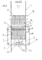
- the device according to the invention (hereinafter referred to as "the screen") is intended to be installed in a channel (1), in which a liquid flows, and in particular water, conveying bulky bodies (waste to be eliminated).
- the screen includes a composite filter screen of bars (2) arranged parallel two by two in a row at a certain distance one the other.
- the bars (2) are stretched or arranged between two beams (3) and (4).
- the beam (3) is fixed to the bottom of the channel (1).
- the beam (4) is located above the channel, substantially vertically to the beam (3).
- the two beams (3) and (4) are interconnected by posts (6), so as to form a frame. Bars (2) traverse each of the two beams (3) and (4) by slots (not shown) cut out in said beams, and are locked at this level by means of locking bars (5).
- the rigidity of the frame formed by the beams (3) and (4) and the posts (6) makes it possible to bars (2) so that they remain perfectly straight.
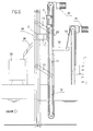
- the device of the invention comprises a cleaning rake (7) of the filter screen. This is located behind said screen, downstream side with respect to the direction of flow of the liquid.
- the teeth (8) which is provided with said rake, are oriented in a direction opposite to the flow direction of the liquid. They have a thickness less than the distance separating two adjacent bars (2).
- the teeth (8) are arranged so that each of them facing a slot defined by two adjacent bars (2). So the teeth (8) of the rake (7) penetrate between the bars (2) and can slide all along the filter screen always remaining between the bars. In the "off" position the free end teeth (8) protrude from the row of bars (2) a certain distance to the side upstream of the filter screen.
- the cleaning rake (7) is fixed on a carriage (9) equipped with wheels or rollers (10), connected to said carriage by means of axes (11).
- the rollers (10) are intended to move along a guide rail (12).
- the carriage (9) is able to slide along rail (12). It is connected to the posts (6) via arms (13) and axes articulation (14).
- the arms (13) and pins (14) allow the rail (12) to approach or away from the filter screen, while remaining parallel to said screen.
- This movement of the rail (12) is provided by means of a geared motor (15).
- This latter is mounted on a support (16) and is connected to the rail (12) via a pinion (17), a chain (18) and an arm (19).
- the weight of the whole constituted by the rail (12) and the carriage (9) is balanced by a counterweight (20). So the distance between the rail (12) and the filter screen can be controlled by the position of the counterweight by through proximity sensors (21).
- the carriage (9) slides along the rail (12) via a geared motor (22) driving a chain (25) secured to the carriage (9), and looped between two pinions (23) and (24).
- the device of the invention also comprises a cleaning comb (27) of the rake (7). It is fixed on a support (28) located above the channel (1), on the upstream side filter screen with respect to the flow direction of the liquid.
- the cleaning comb (27) generally has a construction similar to that of the rake (7).
- Each of the teeth (29) with which it is equipped, is opposite a bar (2), and has substantially the same thickness as said bar. In this way the teeth (8) of the rake (7) are capable of penetrate between the teeth (29) of the comb (27) as shown in Figure 4.
- the device according to the invention operates as follows:
- the geared motor (15) then stops and the gear motor (22) is restarted in the opposite direction to lower the rake (7).
- the teeth (8) of the rake (7) crossing with the teeth (29) of the comb (27), the waste (40) is deposited on said comb as shown in Figure 8.
- the rail (12) is lifted through the geared motor (15), always through the rotation of the arms (13) relative to the hinge pins (14) secured to the posts (6).
- the amplitude of this rotation is defined so that the end (8C) teeth (8) are found between the bars (2) of the filter screen as shown in the figure 9.
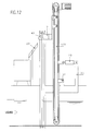
- This position of the rail (12) is maintained until the carriage (7) descends low position, as shown in Figure 10. This avoids driving to the low (with the lower part (8D) teeth (8)) waste that could have stopped on filter screen in between.
- the gearmotor (22) is then stopped and, via of the geared motor (15), the rail (12) is returned to the starting position shown on the figure 5.
- the upper part of the teeth (29) of the comb (27) is inclined. This allows the lower part (8D) of the teeth (8) of the rake (7) of push to a storage bin (30), the waste deposited on the cleaning comb during the previous cycle.
- the rake (7) fills two functions: on the one hand, it deposits on the comb (27) the waste of the cleaning cycle in progress, and on the other hand, it pushes towards the bucket (30) the waste deposited during the cycle of previous cleaning.
- the filter screen may be vertical or inclined relative to the horizontal.
- the bars (2) can be connected to the beams (3) and (4) by any other means than that described previously. So each bar can be welded on the beam or be stretched through a threaded rod welded to the bar and a nut.
- the bars of the filter screen can be stretched between two beams connected by poles or attached independently.
- the bars (2) can be made of metal, plastic or other material. They may have a rectangular, circular section Or other.
- the rake (7) and the cleaning comb (27) can also be made in metal, plastic or different elements made of materials different.
- the device according to the invention can be equipped not with a single rail (12), but with several guide rails of the carriage (9), in particular for very wide screens.
- the guide rail (12) of the carriage (9) can be replaced by another mechanism, which is not necessarily located behind the filter screen, downstream side with respect to the of liquid flow.
- the sliding of the rake (7) between the bars (2) of the filter screen can be ensured by another means that a geared motor (22) actuating the chain (25). So it can be made by one or more racks, by one or more threaded rods or by another means for obtaining the translation of the rake along the filter screen.
- the movements of the rail (12), and more generally the advancement and the retreat rake (7) relative to the filter screen, can be achieved by means other than the geared motor (15) and the chain (18).
- This function can be fulfilled by a jack, by a rack, a threaded rod or another rail guide mechanism to obtain the described course of the rake (7).
- the guide rail can remain motionless.
- the rake (7) can be fixed on another mechanism allowing it approaching or moving away from the filter screen.
- the rake (7) can remain in an intermediate position between the cleaning comb and the surface of the liquid. So, it will go down at the bottom of the filter screen and will resume the position shown in Figure 5 (respectively in Figure 11) only when starting the new cleaning cycle of the filter screen.
- guiding the rake (7) during cleaning of the filter screen of the device according to the invention can be carried out not only by detecting the position of the different elements (proximity detectors, counting of turns, ...) and by independent on the two animation means moving the rake (7) and the rail (12). It is possible to have a single engine combined with a mechanical guiding device to get rid of the second means of animation.
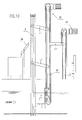
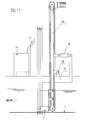
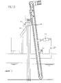
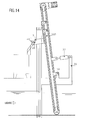
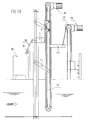
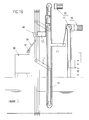
- FIGS. 11 to 16 A variant of the device according to the invention is shown in FIGS. 11 to 16.
- the guide rail (12A) of the carriage (9) is not held by the arms (13), but rests on a fixed support (31) (in this example this support (31) is connected to the filter screen, but it is quite possible that said support (31) is fixed independently on the edges of the channel).
- the rail (12A) is articulated on the support (31) by means of a hinge axis horizontal (32). In doing so, the rail (12A) does not remain parallel to the filter screen as in the case described above, but is likely to pivot about the axis 32.
- the rail (12A) is further secured to a jack (33), whose point of application is constituted by the support (31). This jack (33) thus makes it possible to incline the rail (12A) to approach or move the rake (7) away from the filter screen when said rake is at the bottom or upper part of the filter screen.
- FIGS. 11 to 16 The various sequences of operation of this variant of the device according to the invention are shown in FIGS. 11 to 16, which repeat the same steps as those shown in Figures 5 to 10 respectively.
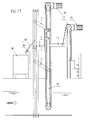
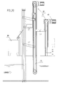
- FIGS. 20 A second variant of the device according to the invention is shown in FIGS. 20.
- the cleaning comb (27) is replaced by a pivoting plate (50), inclined as shown in Figure 17.
- This plate (50) is fixed at its base (28) via a hinge pin (51), allowing it to and to pivot with respect thereto.
- the upper part of the swivel plate (50) bears against the bars (2) of the filter screen, by simple gravity.
- the rake (7) is moved away from the filter screen, so that the teeth (8) penetrate entirely between the bars (2) of said filter screen, as shown in the figure 20. No longer being worn by the teeth (8), the waste (40) falls on the plate (50). As a corollary, the rake (7) returns to its initial position towards the end bottom of the filter screen, the teeth (8) always remaining inside the filter screen to not hang the pivot plate (50) during this down stroke.
- the pivoting plate (50) can be animated by another independent means rake (7). Instead of pivoting, it can also back up or, more generally, move one way or another to always perform the same function, it's up to say let the rake (7) pass during his ascent, and lean again against the filter screen when the rake has passed over it, and position itself indented by report to the filter screen to release the waste that falls on said plate.
- the whole point of the device according to the invention is conceived within the framework of the sieving / screening of liquid effluents and waste water. Indeed, besides simplicity of construction, it can be easily installed in a very deep channel and offers the possibility to significantly reduce the filtration mesh by freeing mechanical problems.
Landscapes
- Chemical & Material Sciences (AREA)
- Chemical Kinetics & Catalysis (AREA)
- Engineering & Computer Science (AREA)
- General Engineering & Computer Science (AREA)
- Mechanical Engineering (AREA)
- Civil Engineering (AREA)
- Structural Engineering (AREA)
- Filtration Of Liquid (AREA)
Applications Claiming Priority (2)
| Application Number | Priority Date | Filing Date | Title |
|---|---|---|---|
| FR0309136A FR2857994B1 (fr) | 2003-07-25 | 2003-07-25 | Dispositif de degrillage/tamisage d'un liquide charge en corps volumineux, et procede de degrillage/tamisage d'un tel liquide mettant en oeuvre ce dispositif |
| FR0309136 | 2003-07-25 |
Publications (1)
| Publication Number | Publication Date |
|---|---|
| EP1500749A1 true EP1500749A1 (de) | 2005-01-26 |
Family
ID=33484705
Family Applications (1)
| Application Number | Title | Priority Date | Filing Date |
|---|---|---|---|
| EP04102535A Withdrawn EP1500749A1 (de) | 2003-07-25 | 2004-06-04 | Vorrichtung zum Filtern/Sieben einer mit Feststoffen beladenen Flüssigkeit und dazugehöriges Sieb-/Filterverfahren |
Country Status (2)
| Country | Link |
|---|---|
| EP (1) | EP1500749A1 (de) |
| FR (1) | FR2857994B1 (de) |
Cited By (3)
| Publication number | Priority date | Publication date | Assignee | Title |
|---|---|---|---|---|
| CN112681057A (zh) * | 2021-01-27 | 2021-04-20 | 上海姿耀玥汽车用品有限公司 | 一种能够净化汽车尾气的马路路面装置 |
| CN114249445A (zh) * | 2021-12-25 | 2022-03-29 | 鄂尔多斯职业学院 | 一种处理有机化工污水的装置 |
| CN114870476A (zh) * | 2022-06-16 | 2022-08-09 | 邵阳学院 | 一种环境规划工程用污水过滤装置 |
Citations (5)
| Publication number | Priority date | Publication date | Assignee | Title |
|---|---|---|---|---|
| GB1407089A (en) * | 1971-10-04 | 1975-09-24 | Roeder W | Apparatus for cleaning a collecting rake and method for its operation |
| FR2532863A1 (fr) * | 1982-09-15 | 1984-03-16 | Degremont Sa | Degrilleur droit a commande pneumatique |
| DE3818501A1 (de) * | 1988-05-31 | 1989-12-07 | Karl Kraus | Reinigungsrechen |
| WO2001088291A1 (en) * | 2000-05-15 | 2001-11-22 | Zygmunt Czekala | Self-cleaning device, especially for trash screening |
| US20030189015A1 (en) * | 2002-04-08 | 2003-10-09 | Roumen Kaltchev | Device for screening/sieving a liquid loaded with bulk material, and procedure for screening/sieving such a liquid |
-
2003
- 2003-07-25 FR FR0309136A patent/FR2857994B1/fr not_active Expired - Lifetime
-
2004
- 2004-06-04 EP EP04102535A patent/EP1500749A1/de not_active Withdrawn
Patent Citations (5)
| Publication number | Priority date | Publication date | Assignee | Title |
|---|---|---|---|---|
| GB1407089A (en) * | 1971-10-04 | 1975-09-24 | Roeder W | Apparatus for cleaning a collecting rake and method for its operation |
| FR2532863A1 (fr) * | 1982-09-15 | 1984-03-16 | Degremont Sa | Degrilleur droit a commande pneumatique |
| DE3818501A1 (de) * | 1988-05-31 | 1989-12-07 | Karl Kraus | Reinigungsrechen |
| WO2001088291A1 (en) * | 2000-05-15 | 2001-11-22 | Zygmunt Czekala | Self-cleaning device, especially for trash screening |
| US20030189015A1 (en) * | 2002-04-08 | 2003-10-09 | Roumen Kaltchev | Device for screening/sieving a liquid loaded with bulk material, and procedure for screening/sieving such a liquid |
Cited By (3)
| Publication number | Priority date | Publication date | Assignee | Title |
|---|---|---|---|---|
| CN112681057A (zh) * | 2021-01-27 | 2021-04-20 | 上海姿耀玥汽车用品有限公司 | 一种能够净化汽车尾气的马路路面装置 |
| CN114249445A (zh) * | 2021-12-25 | 2022-03-29 | 鄂尔多斯职业学院 | 一种处理有机化工污水的装置 |
| CN114870476A (zh) * | 2022-06-16 | 2022-08-09 | 邵阳学院 | 一种环境规划工程用污水过滤装置 |
Also Published As
| Publication number | Publication date |
|---|---|
| FR2857994B1 (fr) | 2006-11-10 |
| FR2857994A1 (fr) | 2005-01-28 |
Similar Documents
| Publication | Publication Date | Title |
|---|---|---|
| EP0979340B1 (de) | Führungsvorrichtung für flexibles hubtor | |
| EP2554231A1 (de) | Sieb mit zylindrischem Filterpaneel für Wasserentnahmestelle | |
| BE1014506A3 (fr) | Dispositif a volet avec element de reintroduction. | |
| FR2941603A1 (fr) | Dispositif pour supporter une pluralite de recipients souples pour liquide. | |
| EP1518036A1 (de) | Verschlusseinrichtung zum wickeln auf eine welle | |
| EP1500749A1 (de) | Vorrichtung zum Filtern/Sieben einer mit Feststoffen beladenen Flüssigkeit und dazugehöriges Sieb-/Filterverfahren | |
| FR2871820A1 (fr) | Tamis a panneau filtrant circulaire pour prise d'eau | |
| FR2497629A1 (de) | ||
| FR2675828A1 (fr) | Barrage flottant. | |
| EP0634981B1 (de) | Einziehbare einrichtung zum bedecken und öffnen eines zwei-oder dreidimensionalen platzes | |
| EP3176356B1 (de) | Schliessvorrichtung | |
| EP0944435A1 (de) | Wasserspiel mit einem zweidimensionalen fliessmuster, überlauf dafür und verfahren zum betrieb der anlage | |
| EP1793043A1 (de) | Bewegliche Hochwasserschutzwand | |
| EP3069774A1 (de) | Staubfilter mit filterkartuschen | |
| EP1413779A1 (de) | Vorrichtung um ein Tier anzubinden | |
| CH655333A5 (fr) | Machine roulante pour excaver le ballast des voies ferrees. | |
| CA3237183A1 (fr) | Dispositif de guidage lateral d'une bande transporteuse sans fin de convoyeur auge | |
| WO2002071375A2 (fr) | Dispositif d'affichage selectif d'affiches | |
| FR2978960A1 (fr) | Conteneur de collecte des dechets dote d'un systeme d'actionnement de trappes perfectionne | |
| EP2730725B1 (de) | Reguliervorrichtung des Durchsatzes eines Skimmers in einem Becken mit Wasserfalleffekt | |
| WO2017118644A1 (fr) | Abri stationnaire de stockage d'au moins une unité de stockage d'énergie électrique | |
| FR3114804A1 (fr) | Machine de retournement d’objet rigide de forme allongée | |
| EP2023778B1 (de) | Sichere basis für eine matte zum windelwechseln | |
| EP4278045B1 (de) | Vorrichtung zur entfernung von schwimmendem abfall zur reinigung von wasserläufen | |
| FR2553803A1 (fr) | Degrilleur automatique |
Legal Events
| Date | Code | Title | Description |
|---|---|---|---|
| PUAI | Public reference made under article 153(3) epc to a published international application that has entered the european phase |
Free format text: ORIGINAL CODE: 0009012 |
|
| AK | Designated contracting states |
Kind code of ref document: A1 Designated state(s): AT BE BG CH CY CZ DE DK EE ES FI FR GB GR HU IE IT LI LU MC NL PL PT RO SE SI SK TR |
|
| AX | Request for extension of the european patent |
Extension state: AL HR LT LV MK |
|
| 17P | Request for examination filed |
Effective date: 20050513 |
|
| AKX | Designation fees paid |
Designated state(s): AT BE BG CH CY CZ DE DK EE ES FI FR GB GR HU IE IT LI LU MC NL PL PT RO SE SI SK TR |
|
| STAA | Information on the status of an ep patent application or granted ep patent |
Free format text: STATUS: THE APPLICATION IS DEEMED TO BE WITHDRAWN |
|
| 18D | Application deemed to be withdrawn |
Effective date: 20060804 |