EP1500530B1 - Mounting of a rigid axle suspension to vehicle frame comprising a spring catch - Google Patents
Mounting of a rigid axle suspension to vehicle frame comprising a spring catch Download PDFInfo
- Publication number
- EP1500530B1 EP1500530B1 EP04015012A EP04015012A EP1500530B1 EP 1500530 B1 EP1500530 B1 EP 1500530B1 EP 04015012 A EP04015012 A EP 04015012A EP 04015012 A EP04015012 A EP 04015012A EP 1500530 B1 EP1500530 B1 EP 1500530B1
- Authority
- EP
- European Patent Office
- Prior art keywords
- rocker
- retaining
- bearing block
- spring
- retaining pin
- Prior art date
- Legal status (The legal status is an assumption and is not a legal conclusion. Google has not performed a legal analysis and makes no representation as to the accuracy of the status listed.)
- Expired - Lifetime
Links
Images

Classifications
-
- B—PERFORMING OPERATIONS; TRANSPORTING
- B60—VEHICLES IN GENERAL
- B60G—VEHICLE SUSPENSION ARRANGEMENTS
- B60G7/00—Pivoted suspension arms; Accessories thereof
- B60G7/04—Buffer means for limiting movement of arms
-
- B—PERFORMING OPERATIONS; TRANSPORTING
- B60—VEHICLES IN GENERAL
- B60G—VEHICLE SUSPENSION ARRANGEMENTS
- B60G11/00—Resilient suspensions characterised by arrangement, location or kind of springs
- B60G11/02—Resilient suspensions characterised by arrangement, location or kind of springs having leaf springs only
- B60G11/04—Resilient suspensions characterised by arrangement, location or kind of springs having leaf springs only arranged substantially parallel to the longitudinal axis of the vehicle
-
- B—PERFORMING OPERATIONS; TRANSPORTING
- B60—VEHICLES IN GENERAL
- B60G—VEHICLE SUSPENSION ARRANGEMENTS
- B60G11/00—Resilient suspensions characterised by arrangement, location or kind of springs
- B60G11/02—Resilient suspensions characterised by arrangement, location or kind of springs having leaf springs only
- B60G11/10—Resilient suspensions characterised by arrangement, location or kind of springs having leaf springs only characterised by means specially adapted for attaching the spring to axle or sprung part of the vehicle
- B60G11/12—Links, pins, or bushes
-
- B—PERFORMING OPERATIONS; TRANSPORTING
- B60—VEHICLES IN GENERAL
- B60G—VEHICLE SUSPENSION ARRANGEMENTS
- B60G2202/00—Indexing codes relating to the type of spring, damper or actuator
- B60G2202/10—Type of spring
- B60G2202/11—Leaf spring
- B60G2202/112—Leaf spring longitudinally arranged
-
- B—PERFORMING OPERATIONS; TRANSPORTING
- B60—VEHICLES IN GENERAL
- B60G—VEHICLE SUSPENSION ARRANGEMENTS
- B60G2204/00—Indexing codes related to suspensions per se or to auxiliary parts
- B60G2204/10—Mounting of suspension elements
- B60G2204/12—Mounting of springs or dampers
- B60G2204/121—Mounting of leaf springs
-
- B—PERFORMING OPERATIONS; TRANSPORTING
- B60—VEHICLES IN GENERAL
- B60G—VEHICLE SUSPENSION ARRANGEMENTS
- B60G2204/00—Indexing codes related to suspensions per se or to auxiliary parts
- B60G2204/40—Auxiliary suspension parts; Adjustment of suspensions
- B60G2204/43—Fittings, brackets or knuckles
-
- B—PERFORMING OPERATIONS; TRANSPORTING
- B60—VEHICLES IN GENERAL
- B60G—VEHICLE SUSPENSION ARRANGEMENTS
- B60G2204/00—Indexing codes related to suspensions per se or to auxiliary parts
- B60G2204/40—Auxiliary suspension parts; Adjustment of suspensions
- B60G2204/45—Stops limiting travel
Definitions
- the invention relates to a sprung suspension of a rigid axle on the chassis frame of a vehicle, in particular trucks or buses, with features specified in the preamble of claim 1 Art.
- the invention is based on a sprung suspension of a rigid axle as from GB 1202482 A known.
- a leaf spring is hinged to the front of a frame-fixed bracket and the rear of a lower bearing point of a rocker.
- the rocker itself is hinged in its upper part to a frame fixed bearing block.
- the rocker is one - associated with the breakage of the leaf spring - spring catch device assigned.
- This has a rear bearing block spaced from the upper swing bearing point and shifted down rear catch bolt, on which the rocker comes in the event of a spring break with its rear edge approximately centrally to the plant.
- This known solution therefore requires a downwardly extended and correspondingly widened bearing block for the mounting of the rocker and suitable arrangement of the catch bolt.
- the spring catch device according to the invention is immediately effective when the leaf spring breaks at its front attachment point.
- the leaf spring shifts in this case to the rear.
- this movement is stopped after a short way, because the deflected backward at this longitudinal displacement rocker comes after a short angular movement with the stop surface at its catching area on the bearing block fixed catch bolt to the plant.
- the axle of the rigid axle although a bit crooked, that is, no longer perpendicular to the vehicle longitudinal axis, but this disadvantage can be compensated for slower driving on the wheel steering.
- the safety gear according to the invention does not interfere with the deflection of the chassis frame to the axis, since in this case the rocker is not swung back to the extent of the fraction of the spring.
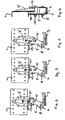
- FIG. 5 There is a vehicle, z. As trucks or buses, a portion of a part of the chassis forming frame side member 1 shown on which a rigid axle with its axle 2 is sprung articulated and fixed. This purpose is served by either a single spring leaf or a leaf spring package existing leaf spring 3, which is fastened with its front spring eye 4 on a frame-fixed front bearing block 5 and with its rear spring eye 6 on a rocker 7, where the lower bearing 8, hinged and this rocker 7 suspended on a rear frame fixed bearing block 9, wherein the upper bearing point on the rocker 7, with which the connection is made to the bearing block 9, designated 10.
- a shock absorber 11 which is articulated at the top on a frame-fixed bearing block 12 and at the bottom of the axle 2, and a U-shaped stabilizer 13, with its transverse leg on the axle body 2 and with its two U-shaped stabilizer. Legs is hinged to one holding rod 14, which is suspended with its upper end to a frame-fixed block 15. 16 with a stop buffer is designated, which is fastened on top of the leaf spring 3 and in cooperation with a frame-fixed stop surface 17, the Einfederungsweg of the frame 1 with respect to the axle beam 2 limited.
- a correspondingly modified rocker and modified rear bearing block is used in the region of the rear linkage of the leaf spring 3.
- the rocker according to the invention is denoted by 7 'and the rear bearing block according to the invention is denoted by 9'.
- These two components 7 ', 9' are used to form the spring catch device according to the invention, namely as follows.
- a catch pin 18 is arranged above and spaced from the upper bearing point 10 for the rocker 7'.
- the rocker 7 'seen from the upper bearing 10 is extended upwards to the area of the catch bolt 18 by a catching area 19 and has at least one stop surface 20 at this catch area 19 in the amount of the catch bolt 18.
- a stop surface 20 is provided, which is given by a section on a - viewed forwardly in the direction of travel - front end face on the catch portion 19 of the rocker 7 ', which stop surface 20 engages behind the catch pin 18.
- two abutment surfaces namely a rear abutment surface 20 and a front abutment surface 21, are provided on or in the catching region 19 of the rocker 7 '.
- this is provided in the catching area 19 of the rocker 7 'a slot or a transverse bore with respect to the diameter of the catch bolt 18 corresponding larger diameter, in which slot or transverse bore of the catch pin 18 dips and whose or front and rear arcuate wall portion, the front and rear abutment surface 20, 21 form.
- an upwardly open mouth is provided on the catching area 19 of the rocker 7 ', whose front and rear boundary surfaces form the front and rear abutment surfaces 20, 21.
- Two abutment surfaces 20, 21 have the advantage that when broken leaf spring 3 not only a forward drive, but on a reverse driving with each set on the frame-side stop leaf spring 3 is possible.
- the catch bolt 18 may be formed for example by a cylindrical steel bolt, which penetrates a transverse bore in the rear bearing block 9 ', this inside and outside outstanding and on the bearing block 9' is welded.
- the rocker 7 ' can be formed, for example, by two identical and mutually parallel tabs - see FIG. 4 - which are held at a parallel distance via a spacer sleeve within the front spring eye 6 and a spacer sleeve 22 at the rear bearing block 9'.
Landscapes
- Engineering & Computer Science (AREA)
- Mechanical Engineering (AREA)
- Vehicle Body Suspensions (AREA)
- Body Structure For Vehicles (AREA)
Abstract
Description
Die Erfindung betrifft eine gefederte Aufhängung einer Starrachse am Fahrgestell-Rahmen eines Fahrzeugs, insbesondere Lastkraftwagen oder Omnibus, mit Merkmalen der im Oberbegriff des Anspruchs 1 angegebenen Art.The invention relates to a sprung suspension of a rigid axle on the chassis frame of a vehicle, in particular trucks or buses, with features specified in the preamble of claim 1 Art.
Die Erfindung geht aus von einer gefederten Aufhängung einer Starrachse wie aus der
Bei gebauten Nutzfahrzeugen der Anmelderin, die bisher mit keiner solchen Federfangvorrichtung ausgestattet waren, ist die Schwinge - wie aus Fig. 5 ersichtlich, am unteren Ende eines hinteren Lagerbocks gelagert.When built commercial vehicles of the Applicant, which were previously equipped with no such spring catch device, the rocker - as shown in Fig. 5, stored at the lower end of a rear bearing block.
Rein der Vollständigkeit wegen sei auch noch auf die aus der
Es ist ausgehend von der
Diese Aufgabe wird bei einer gefederten Starrachs-Aufhängung der gattungsgemäßen Art durch die im Kennzeichen des Anspruchs 1 angegebene Bauart der Federfangvorrichtung gelöst.This object is achieved in a sprung rigid suspension of the generic type by the specified in the characterizing part of claim 1 type of spring catching device.
Dabei ist der Fangbolzen erfindungsgemäß am hinteren Lagerbock oberhalb und beabstandet von der oberen Lagerstelle der Schwinge angeordnet, außerdem ist die Schwinge um einen Fangbereich nach oben bis in den Fangbereich verlängert und weist an diesem Fangbereich in Höhe des Fangbolzens wenigstens eine Anschlagfläche auf, mit der sie im Fall eines Federbruchs am Fangbolzen zur Anlage kommt.In this case, the catch bolt according to the invention at the rear bearing block above and spaced from the upper bearing of the rocker, also the rocker is extended by a catch area up to the catch area and has at this catch area in height of the catch bolt at least one stop surface on, with them in the case of a spring break on the catch bolt comes to rest.
Die erfindungsgemäße Federfangvorrichtung wird sofort wirksam, wenn die Blattfeder an ihrer vorderen Befestigungsstelle bricht. Die Blattfeder verschiebt sich in diesem Fall nach hinten. Diese Bewegung wird aber bereits nach kurzem Weg gestoppt, weil die bei dieser Längsverschiebung nach hinten ausgelenkte Schwinge schon nach kurzer Winkelbewegung mit der Anschlagfläche an ihrem Fangbereich am lagerbockfesten Fangbolzen zur Anlage kommt. Es steht dann der Achskörper der Starrachse zwar etwas schief, das heißt, nicht mehr senkrecht zur Fahrzeug-Längsachse, dieser Nachteil lässt sich aber bei langsamer Weiterfahrt über die Radlenkung ausgleichen. Im Normalbetrieb behindert die erfindungsgemäße Fangvorrichtung die Einfederung des Fahrgestell-Rahmens zur Achse hin nicht, da hierbei die Schwinge nicht in dem Maß wie beim Bruch der Feder nach hinten ausgeschwenkt wird.The spring catch device according to the invention is immediately effective when the leaf spring breaks at its front attachment point. The leaf spring shifts in this case to the rear. However, this movement is stopped after a short way, because the deflected backward at this longitudinal displacement rocker comes after a short angular movement with the stop surface at its catching area on the bearing block fixed catch bolt to the plant. It is then the axle of the rigid axle, although a bit crooked, that is, no longer perpendicular to the vehicle longitudinal axis, but this disadvantage can be compensated for slower driving on the wheel steering. In normal operation, the safety gear according to the invention does not interfere with the deflection of the chassis frame to the axis, since in this case the rocker is not swung back to the extent of the fraction of the spring.
Vorteilhafte Ausgestaltungen oder Details der erfindungsgemäßen Lösung sind in den Unteransprüchen gekennzeichnet.Advantageous embodiments or details of the solution according to the invention are characterized in the subclaims.
Nachstehend ist die Erfindung anhand mehrerer in der Zeichnung dargestellter Ausführungsbeispiele noch näher erläutert. In der Zeichnung zeigen:
- Fig. 1, 2 und 3 je
- ein Ausführungsbeispiel der erfindungsgemäßen Federfangvorrichtung in Seitenansicht,
- Fig. 4
- die Federfangvorrichtung gemäß Fig. 1 in Ansicht von hinten, und
- Fig. 5
- eine gefederte Starrachs-Aufhängung bekannter Bauart, der es aufgabengemäß eine Federfangvorrichtung zuzuordnen galt.
- Fig. 1, 2 and 3 each
- An embodiment of the spring catch device according to the invention in side view,
- Fig. 4
- the spring catch device of FIG. 1 in rear view, and
- Fig. 5
- a sprung rigid axle suspension of known type, which was assigned task according to a spring catch device.
Zunächst wird zum besseren Verständnis der Erfindung auf den Stand der Technik gemäß Fig. 5 eingegangen. Dort ist von einem Fahrzeug, z. B. Lastkraftwagen oder Omnibus, ein Abschnitt eines ein Teil des Fahrgestells bildenden Rahmen-Längsträgers 1 gezeigt, an dem eine Starrachse mit ihrem Achskörper 2 gefedert angelenkt und befestigt ist. Hierzu dient eine entweder aus einem einzigen Federblatt oder einem Blattfederpaket bestehende Blattfeder 3, die mit ihrem vorderen Federauge 4 an einem rahmenfesten vorderen Lagerbock 5 befestigt sowie mit ihrem hinteren Federauge 6 an einer Schwinge 7, dort deren unterer Lagerstelle 8, angelenkt und über diese Schwinge 7 fliegend an einem hinteren rahmenfesten Lagerbock 9 aufgehängt ist, wobei die obere Lagerstelle an der Schwinge 7, mit der die Verbindung zum Lagerbock 9 hergestellt ist, mit 10 bezeichnet ist. Als weitere Teile der Starrachs-Aufhängung sind zu nennen ein Stoßdämpfer 11, der oben an einem rahmenfesten Lagerbock 12 und unten am Achskörper 2 angelenkt ist, und ein U-förmiger Stabilisator 13, der mit seinem Querschenkel am Achskörper 2 und mit seinen beiden U-Schenkeln an jeweils einem Haltestab 14 angelenkt ist, der mit seinem oberen Ende an einem rahmenfesten Bock 15 aufgehängt ist. Mit 16 ist ein Anschlagpuffer bezeichnet, der oben auf der Blattfeder 3 befestigt ist und im Zusammenwirken mit einer rahmenfesten Anschlagfläche 17 den Einfederungsweg des Rahmens 1 in Bezug auf den Achskörper 2 begrenzt.First, for a better understanding of the invention, the state of the art according to FIG. 5 will be discussed. There is a vehicle, z. As trucks or buses, a portion of a part of the chassis forming frame side member 1 shown on which a rigid axle with its axle 2 is sprung articulated and fixed. This purpose is served by either a single spring leaf or a leaf spring package existing leaf spring 3, which is fastened with its
Erfindungsgemäß kommt im Bereich der hinteren Anlenkung der Blattfeder 3 eine entsprechend abgewandelte Schwinge und abgewandelter hinterer Lagerbock zur Anwendung. Die erfindungsgemäße Schwinge ist mit 7' und der erfindungsgemäße hintere Lagerbock ist mit 9' bezeichnet. Diese beiden Bauteile 7', 9' sind zur Bildung der erfindungsgemäßen Federfangvorrichtung herangezogen und zwar wie folgt. Am hinteren Lagerbock 9' ist ein Fangbolzen 18 angeordnet und zwar oberhalb und beabstandet von der oberen Lagerstelle 10 für die Schwinge 7'. Außerdem ist die Schwinge 7' von der oberen Lagerstelle 10 aus gesehen nach oben bis in den Bereich des Fangbolzens 18 um einen Fangbereich 19 verlängert und weist an diesem Fangbereich 19 in Höhe des Fangbolzens 18 wenigstens eine Anschlagfläche 20 auf. Mit dieser Anschlagfläche 20 kommt die Schwinge 7' im Falle eines Bruches der Blattfeder 3 in ihren vorderen Lagerbereich 4 aufgrund einer dadurch während der Vorwärtsfahrt bedingten Längsverschiebung der Blattfeder 3 nach hinten und ihrer damit einhergehenden Verschwenkung um die obere Lagerstelle 10 am Fangbolzen 18 zum Anschlag. Dadurch wird eine gebrochene Blattfeder 3 nach hinten sicher am Rahmen abgestützt, was eine Weiterfahrt des Fahrzeugs mit verminderter Geschwindigkeit für eine begrenzte Strecke, z. B. zur nächsten Werkstatt oder Servicecenter ermöglicht. Bei intakter Blattfeder 3 bleibt die Anschlagfläche 20 in jedem Einfederungszustand des Rahmens 1 gegenüber dem Starrachskörper 2 mehr oder weniger weit vom Fangbolzen 18 beabstandet.According to the invention, a correspondingly modified rocker and modified rear bearing block is used in the region of the rear linkage of the leaf spring 3. The rocker according to the invention is denoted by 7 'and the rear bearing block according to the invention is denoted by 9'. These two components 7 ', 9' are used to form the spring catch device according to the invention, namely as follows. At the rear bearing block 9 'a
Nachstehend ist auf Details der verschiedenen in der Zeichnung dargestellten Ausführungsbeispiele der Erfindung eingegangen.Hereinafter, details of the various exemplary embodiments of the invention illustrated in the drawing are described.
Im Fall von Fig. 1 ist eine Anschlagfläche 20 vorgesehen, die durch einen Abschnitt an einer - in Fahrtrichtung vorwärts gesehen - vorderen Stirnfläche am Fangbereich 19 der Schwinge 7' gegeben ist, welche Anschlagfläche 20 den Fangbolzen 18 hintergreift.In the case of Fig. 1, a
In den Fällen von Fig. 2 und 3 sind zwei Anschlagflächen, nämlich eine hintere Anschlagfläche 20 und eine vordere Anschlagfläche 21, am bzw. im Fangbereich 19 der Schwinge 7' vorgesehen.In the cases of FIGS. 2 and 3, two abutment surfaces, namely a
Im Fall des Beispiels von Fig. 2 ist hierzu im Fangbereich 19 der Schwinge 7' ein Langloch oder eine Querbohrung mit gegenüber dem Durchmesser des Fangsbolzens 18 entsprechend größeren Durchmesser vorgesehen, in welches Langloch bzw. welche Querbohrung der Fangbolzen 18 eintaucht und dessen bzw. deren vorderer und hinterer bogenförmiger Wandabschnitt die vordere und hintere Anschlagfläche 20, 21 bilden.In the case of the example of FIG. 2, this is provided in the
Im Fall des Beispiels gemäß Fig. 3 ist am Fangbereich 19 der Schwinge 7' ein nach oben offenes Maul vorgesehen, dessen vordere und hintere Begrenzungsfläche die vordere und hintere Anschlagfläche 20, 21 bilden.In the case of the example according to FIG. 3, an upwardly open mouth is provided on the
Zwei Anschlagflächen 20, 21 haben den Vorteil, dass bei gebrochener Blattfeder 3 nicht nur eine Vorwärtsfahrt, sondern auf ein Rückwärtsfahren mit jeweils auf rahmenseitigen Anschlag gesetzter Blattfeder 3 möglich ist.Two
Der Fangbolzen 18 kann beispielsweise durch einen zylindrischen Stahlbolzen gebildet sein, der eine Querbohrung im hinteren Lagerbock 9', diesen innen- und außenseitig überragend durchdringt und am Lagerbock 9' angeschweißt ist.The
Die erfindungsgemäße Schwinge 7' kann beispielsweise durch zwei identisch und parallel zueinander angeordnete Laschen - siehe Fig. 4 - gebildet sein, die über eine Distanzhülse innerhalb des vorderen Federauges 6 und eine Distanzhülse 22 am hinteren Lagerbock 9' auf Parallelabstand gehalten sind.The rocker 7 'according to the invention can be formed, for example, by two identical and mutually parallel tabs - see FIG. 4 - which are held at a parallel distance via a spacer sleeve within the
Claims (6)
- Sprung suspension system for a rigid axle in a chassis frame of a vehicle, particularly a truck or bus/coach, whereby the lower end of the axle body (2) is fastened to a leaf spring (3) whose front end is located on a frame-mounted bearing block (5) and whose rear end is located on a lower bearing point (8) of a rocker (7), which in turn is slewably located via an upper bearing point (10) on a frame-mounted rear bearing block (9) and to which a spring retaining device is allocated - which spring retaining device becomes effective in the front fastening area (4) of the leaf spring (3) should said spring (3) rupture - and features a retaining pin (18) arranged at the rear bearing block (9) and located at a distance to the upper bearing point (10) of the rocker (7) which contacts said retaining pin (18) with at least one stop face if the spring (3) breaks, but, if the leaf spring (3) is intact, remains at a more or less large distance relative to the retaining pin (18) during any compression condition of the frame (1) relative to the axle body (2) of the rigid axle, characterised in that the retaining pin (18) is located at the rear bearing block (9') above and at a distance to the upper bearing point (10) on the rocker (7'), that the rocker (7') is extended upwards by a retaining area (19) as far as into the area of the retaining pin (18) and that the at least one stop face (20, 21) is arranged at the height of the retaining pin (18) in this retaining area (19) of the rocker (7').
- Suspension system according to Claim 1, characterised in that only one stop face (20) is provided, namely in the form of a section on - as viewed in forward-driving direction - the front end face in the retaining area (19) on the rocker (7'), which stop face (20) encompasses the retaining pin (18).
- Suspension system according to Claim 1, characterised in that two stop faces (20, 21), namely a rear one (20) and a front one (21), are provided at or in the retaining area (19) of the rocker (7').
- Suspension system according to Claim 3, characterised in that a longitudinal hole or a transverse bore with a diameter larger than that of the retaining pin (18) is provided in the retaining area (19) of the rocker (7'), into which hole or bore the retaining pin (18) penetrates, the front and rear wall sections of said hole or bore forming the stop faces (20, 21).
- Suspension system according to Claim 3, characterised in that a jaw open towards the top is provided in the retaining area (19) of the rocker (7'), the front and rear limiting faces of which jaw forming the two stop faces (20, 21).
- Suspension system according to Claim 1, characterised in that the retaining pin (18) is formed by a cylindrical steel pin which penetrates a transverse bore in the rear bearing block (9'), projects beyond said rear bearing block (9') on the inside and outside and is welded to the bearing block (9').
Applications Claiming Priority (2)
| Application Number | Priority Date | Filing Date | Title |
|---|---|---|---|
| AT0114103A AT413362B (en) | 2003-07-21 | 2003-07-21 | SPRING SUSPENSION OF A STARRACHSE ON THE CHASSIS FRAME OF A VEHICLE, WITH A SPRING Catcher |
| AT11412003 | 2003-07-21 |
Publications (2)
| Publication Number | Publication Date |
|---|---|
| EP1500530A1 EP1500530A1 (en) | 2005-01-26 |
| EP1500530B1 true EP1500530B1 (en) | 2007-12-12 |
Family
ID=33479922
Family Applications (1)
| Application Number | Title | Priority Date | Filing Date |
|---|---|---|---|
| EP04015012A Expired - Lifetime EP1500530B1 (en) | 2003-07-21 | 2004-06-25 | Mounting of a rigid axle suspension to vehicle frame comprising a spring catch |
Country Status (3)
| Country | Link |
|---|---|
| EP (1) | EP1500530B1 (en) |
| AT (2) | AT413362B (en) |
| DE (1) | DE502004005680D1 (en) |
Families Citing this family (4)
| Publication number | Priority date | Publication date | Assignee | Title |
|---|---|---|---|---|
| DE102005032611B4 (en) * | 2005-07-11 | 2021-01-14 | Iveco Magirus Ag | Leaf spring suspension for commercial vehicles |
| AT504976B1 (en) | 2007-03-09 | 2013-03-15 | Man Truck & Bus Oesterreich Ag | SPRING TRAP |
| DE102018112484B3 (en) | 2018-05-24 | 2019-10-24 | Benteler Automobiltechnik Gmbh | Retaining shackle for holding a leaf spring |
| CN116852926B (en) * | 2023-06-27 | 2026-01-27 | 东风商用车有限公司 | Monolithic spring suspension system and vehicle |
Family Cites Families (5)
| Publication number | Priority date | Publication date | Assignee | Title |
|---|---|---|---|---|
| DE409826C (en) * | 1923-05-03 | 1925-02-16 | Jean Visart | Front spring suspension for motor vehicles |
| BE352896A (en) * | 1928-07-16 | 1928-08-31 | ||
| US1941331A (en) * | 1933-06-01 | 1933-12-26 | Eaton Mfg Co | Vehicle spring |
| GB1202482A (en) * | 1968-01-16 | 1970-08-19 | Ford Motor Co | Motor vehicle leaf spring assembly |
| US4872653A (en) * | 1988-04-11 | 1989-10-10 | Chuchua Brian N | Shackle for use in limiting the movement of an end of a leaf spring in a wheeled vehicle |
-
2003
- 2003-07-21 AT AT0114103A patent/AT413362B/en not_active IP Right Cessation
-
2004
- 2004-06-25 AT AT04015012T patent/ATE380687T1/en not_active IP Right Cessation
- 2004-06-25 EP EP04015012A patent/EP1500530B1/en not_active Expired - Lifetime
- 2004-06-25 DE DE502004005680T patent/DE502004005680D1/en not_active Expired - Lifetime
Also Published As
| Publication number | Publication date |
|---|---|
| ATE380687T1 (en) | 2007-12-15 |
| ATA11412003A (en) | 2005-07-15 |
| EP1500530A1 (en) | 2005-01-26 |
| DE502004005680D1 (en) | 2008-01-24 |
| AT413362B (en) | 2006-02-15 |
Similar Documents
| Publication | Publication Date | Title |
|---|---|---|
| DE69904123T2 (en) | Cross member for a rear suspension system of a motor vehicle | |
| DE19605283B4 (en) | Trailing arm suspension for vehicles | |
| DE2536060A1 (en) | WHEEL SUSPENSION FOR MOTOR VEHICLES | |
| EP0940272A1 (en) | Chassis for a cab-over-engine lorry | |
| EP0798198A1 (en) | Front bearing for tilt cab truck | |
| EP0940320B1 (en) | Chassis for a heavy-duty utility vehicle | |
| DE3047970C2 (en) | Axle suspension for motor vehicles, in particular off-road vehicles | |
| DE10036396B4 (en) | Subframe module for a motor vehicle | |
| DE19809279A1 (en) | Chassis of a heavy commercial vehicle | |
| AT413362B (en) | SPRING SUSPENSION OF A STARRACHSE ON THE CHASSIS FRAME OF A VEHICLE, WITH A SPRING Catcher | |
| EP1967394B1 (en) | Spring trap device | |
| AT413971B (en) | SPRING SUSPENSION OF A STARRACHSE ON THE CHASSIS FRAME OF A VEHICLE, IN PARTICULAR LORRY OR OMNIBUSSES | |
| EP0502311B1 (en) | Axle with steered wheels and pneumatic suspension for a motor vehicle | |
| DE19849474B4 (en) | Suspension of a rear axle of a motor vehicle | |
| EP0940322A1 (en) | Chassis for a heavy-duty utility vehicle | |
| EP0940324A1 (en) | Chassis for a heavy-duty utility vehicle | |
| DE19809196A1 (en) | Chassis of a heavy commercial vehicle | |
| DE1555377A1 (en) | Wheel suspension for motor vehicles | |
| EP1447247B1 (en) | Rigid axle suspension for a vehicle | |
| DE102005032610B4 (en) | Leaf spring suspension for commercial vehicles | |
| AT501922B1 (en) | COMMERCIAL VEHICLE, IN PARTICULAR LORRAINE, WITH SPECIAL SUSPENSION AND STEERING OF TWO ADJOINABLE FRONT AXLES | |
| DE4107305C2 (en) | Air-suspended, steerable wheel-bearing axle of a motor vehicle | |
| EP0940323A1 (en) | Chassis for a heavy-duty utility vehicle | |
| DE3422897C2 (en) | ||
| DE102006010130B4 (en) | Subframe, in particular for motor vehicles |
Legal Events
| Date | Code | Title | Description |
|---|---|---|---|
| PUAI | Public reference made under article 153(3) epc to a published international application that has entered the european phase |
Free format text: ORIGINAL CODE: 0009012 |
|
| 17P | Request for examination filed |
Effective date: 20041118 |
|
| AK | Designated contracting states |
Kind code of ref document: A1 Designated state(s): AT BE BG CH CY CZ DE DK EE ES FI FR GB GR HU IE IT LI LU MC NL PL PT RO SE SI SK TR |
|
| AX | Request for extension of the european patent |
Extension state: AL HR LT LV MK |
|
| RAP1 | Party data changed (applicant data changed or rights of an application transferred) |
Owner name: MAN NUTZFAHRZEUGE OESTERREICH AG |
|
| AKX | Designation fees paid |
Designated state(s): AT DE FR IT SE |
|
| GRAP | Despatch of communication of intention to grant a patent |
Free format text: ORIGINAL CODE: EPIDOSNIGR1 |
|
| GRAS | Grant fee paid |
Free format text: ORIGINAL CODE: EPIDOSNIGR3 |
|
| GRAA | (expected) grant |
Free format text: ORIGINAL CODE: 0009210 |
|
| AK | Designated contracting states |
Kind code of ref document: B1 Designated state(s): AT DE FR IT SE |
|
| REF | Corresponds to: |
Ref document number: 502004005680 Country of ref document: DE Date of ref document: 20080124 Kind code of ref document: P |
|
| REG | Reference to a national code |
Ref country code: SE Ref legal event code: TRGR |
|
| ET | Fr: translation filed | ||
| PLBE | No opposition filed within time limit |
Free format text: ORIGINAL CODE: 0009261 |
|
| STAA | Information on the status of an ep patent application or granted ep patent |
Free format text: STATUS: NO OPPOSITION FILED WITHIN TIME LIMIT |
|
| 26N | No opposition filed |
Effective date: 20080915 |
|
| PGFP | Annual fee paid to national office [announced via postgrant information from national office to epo] |
Ref country code: AT Payment date: 20090615 Year of fee payment: 6 |
|
| PG25 | Lapsed in a contracting state [announced via postgrant information from national office to epo] |
Ref country code: AT Free format text: LAPSE BECAUSE OF NON-PAYMENT OF DUE FEES Effective date: 20100625 |
|
| REG | Reference to a national code |
Ref country code: DE Ref legal event code: R081 Ref document number: 502004005680 Country of ref document: DE Owner name: MAN TRUCK BUS OESTERREICH AG, AT Free format text: FORMER OWNER: MAN NUTZFAHRZEUGE OESTERREICH AG, STEYR, AT Effective date: 20120125 Ref country code: DE Ref legal event code: R081 Ref document number: 502004005680 Country of ref document: DE Owner name: MAN TRUCK & BUS OESTERREICH AG, AT Free format text: FORMER OWNER: MAN NUTZFAHRZEUGE OESTERREICH AG, STEYR, AT Effective date: 20120125 |
|
| REG | Reference to a national code |
Ref country code: FR Ref legal event code: CD Owner name: MAN TRUCK & BUS OSTERREICH AG Effective date: 20120314 |
|
| REG | Reference to a national code |
Ref country code: FR Ref legal event code: PLFP Year of fee payment: 13 |
|
| REG | Reference to a national code |
Ref country code: FR Ref legal event code: PLFP Year of fee payment: 14 |
|
| REG | Reference to a national code |
Ref country code: FR Ref legal event code: PLFP Year of fee payment: 15 |
|
| REG | Reference to a national code |
Ref country code: DE Ref legal event code: R081 Ref document number: 502004005680 Country of ref document: DE Owner name: MAN TRUCK & BUS SE, DE Free format text: FORMER OWNER: MAN TRUCK & BUS OESTERREICH AG, STEYR, AT |
|
| PGFP | Annual fee paid to national office [announced via postgrant information from national office to epo] |
Ref country code: SE Payment date: 20230317 Year of fee payment: 20 |
|
| PGFP | Annual fee paid to national office [announced via postgrant information from national office to epo] |
Ref country code: FR Payment date: 20230622 Year of fee payment: 20 Ref country code: DE Payment date: 20230627 Year of fee payment: 20 |
|
| PGFP | Annual fee paid to national office [announced via postgrant information from national office to epo] |
Ref country code: IT Payment date: 20230620 Year of fee payment: 20 |
|
| REG | Reference to a national code |
Ref country code: DE Ref legal event code: R071 Ref document number: 502004005680 Country of ref document: DE |
|
| REG | Reference to a national code |
Ref country code: SE Ref legal event code: EUG |