EP0940323A1 - Chassis for a heavy-duty utility vehicle - Google Patents
Chassis for a heavy-duty utility vehicle Download PDFInfo
- Publication number
- EP0940323A1 EP0940323A1 EP99101609A EP99101609A EP0940323A1 EP 0940323 A1 EP0940323 A1 EP 0940323A1 EP 99101609 A EP99101609 A EP 99101609A EP 99101609 A EP99101609 A EP 99101609A EP 0940323 A1 EP0940323 A1 EP 0940323A1
- Authority
- EP
- European Patent Office
- Prior art keywords
- strut
- rigid axle
- chassis according
- axle body
- crossbar
- Prior art date
- Legal status (The legal status is an assumption and is not a legal conclusion. Google has not performed a legal analysis and makes no representation as to the accuracy of the status listed.)
- Granted
Links
Images


Classifications
-
- B—PERFORMING OPERATIONS; TRANSPORTING
- B60—VEHICLES IN GENERAL
- B60G—VEHICLE SUSPENSION ARRANGEMENTS
- B60G9/00—Resilient suspensions of a rigid axle or axle housing for two or more wheels
-
- B—PERFORMING OPERATIONS; TRANSPORTING
- B62—LAND VEHICLES FOR TRAVELLING OTHERWISE THAN ON RAILS
- B62D—MOTOR VEHICLES; TRAILERS
- B62D21/00—Understructures, i.e. chassis frame on which a vehicle body may be mounted
- B62D21/11—Understructures, i.e. chassis frame on which a vehicle body may be mounted with resilient means for suspension, e.g. of wheels or engine; sub-frames for mounting engine or suspensions
-
- B—PERFORMING OPERATIONS; TRANSPORTING
- B62—LAND VEHICLES FOR TRAVELLING OTHERWISE THAN ON RAILS
- B62D—MOTOR VEHICLES; TRAILERS
- B62D25/00—Superstructure or monocoque structure sub-units; Parts or details thereof not otherwise provided for
- B62D25/08—Front or rear portions
- B62D25/088—Details of structures as upper supports for springs or dampers
-
- B—PERFORMING OPERATIONS; TRANSPORTING
- B62—LAND VEHICLES FOR TRAVELLING OTHERWISE THAN ON RAILS
- B62D—MOTOR VEHICLES; TRAILERS
- B62D33/00—Superstructures for load-carrying vehicles
- B62D33/06—Drivers' cabs
- B62D33/063—Drivers' cabs movable from one position into at least one other position, e.g. tiltable, pivotable about a vertical axis, displaceable from one side of the vehicle to the other
- B62D33/067—Drivers' cabs movable from one position into at least one other position, e.g. tiltable, pivotable about a vertical axis, displaceable from one side of the vehicle to the other tiltable
-
- B—PERFORMING OPERATIONS; TRANSPORTING
- B60—VEHICLES IN GENERAL
- B60G—VEHICLE SUSPENSION ARRANGEMENTS
- B60G2206/00—Indexing codes related to the manufacturing of suspensions: constructional features, the materials used, procedures or tools
- B60G2206/01—Constructional features of suspension elements, e.g. arms, dampers, springs
- B60G2206/60—Subframe construction
- B60G2206/602—Single transverse beam
-
- B—PERFORMING OPERATIONS; TRANSPORTING
- B60—VEHICLES IN GENERAL
- B60G—VEHICLE SUSPENSION ARRANGEMENTS
- B60G2300/00—Indexing codes relating to the type of vehicle
- B60G2300/14—Buses
Definitions
- the invention relates to a chassis of a heavy commercial vehicle with features according to the preamble of claim 1.
- the chassis according to the invention is part of a heavy commercial vehicle, which is a truck, especially the front-link design tilting cab, with attachments and superstructures of various types, including those trade for special purposes, a tractor unit or an omnibus can.
- the rigid axle according to the invention can be used as a front axle, trailing axle or Leading axle with steerable or non-steerable wheels are used.
- a front axle is an example of the rigid axle according to the invention shown. From the chassis are in the drawing as parts of the frame whose two side members are labeled 1 and 2.
- the rigid axle shown includes all suspension, suspension and Damping elements from the following main parts, namely a rigid axle body 3, a left trailing arm 4 and right trailing arm 5, a left strut 6 with air or coil spring 7 and this coaxial shock absorber 8, a right Strut 9 with air or coil spring 10 and this coaxial shock absorber 11, a Panhard rod 15 and a - seen from the front - U-shaped cross member 38, which consists of a left strut holder 12, a right strut holder 13 and a crossbar 14 is composed.
- Each of them is outside on one Frame side members 1 and 2 attached and used for frame-side articulation of the rigid axle according to the invention and in the present example also beyond as a holding, supporting and bearing element for a larger number of vehicle parts to be attached.
- the rigid axle according to the invention then brings out its advantages in particular, if - as shown - in the manner of a self-stabilizing torsion beam axle is trained.
- the rigid axle is basically designed that only the Panhard rod 15 is necessary for their transverse guidance and they without the Previously necessary in heavy commercial vehicles to limit swaying U-shaped stabilizer works, but its function is imprinted on a composite is that of the rigid axle body 3 and the two attached to it Trailing arms 4, 5 assembled.
- the rigid axle body 3 obeys in a straight central region 18 between the two trailing arms 4, 5 connected to it are designed to be torsionally defined.
- each has the two equally long trailing arms 4, 5 between his foot 23 and 24 and one other end existing bearing eye 26 or 27 with a rod-shaped area one that changes in size over the length to the bearing eye 26 or 27 decreasing cross-section.
- the two trailing arms 4, 5 to the vehicle longitudinal center axis mirror-symmetrical and - viewed from above - so swept towards each other are connected to the rigid axle body 3 so that they enclose a trapezoidal surface, the distance between their bearing eyes 26 and 27 with which they each the frame-mounted multi-function end shields 16 and 17 articulated are, is smaller than the distance between their axles-side feet 23 and 24. If the rigid axle according to the invention is installed in the vehicle, the two run Trailing arms 4, 5 - viewed from the side - starting from the rigid axle body 3 directed obliquely upwards to the multi-functional position shields 16 on the frame or 17 out.
- each strut 6 and 9 is spatially above and laterally outside of the adjacent frame side member 1 or 2 on one the two strut brackets 12 and 13 supported and attached.
- the two strut holders according to the invention, 12 and 13 form together with the crossbar 14 the - seen from the front - U-shaped cross member 38, the cross member 14th the rigid axle body 3 and the Panhard rod 15 forming a roof at a short distance above bridged and also the two frame side members 1, 2 stabilizing connects with each other.
- the cross member 14 is hat-shaped in cross section Pressed sheet metal part, optionally also forged or cast part, formed a straight central section 39 and on both sides of the same one pulled up obliquely End portion 40 and 41 has.
- a mouth with which the strut holder 12 or 13 to be connected is attacked on the outside.
- Each mouth is cut out by a cutout 42 or 43 in Upper flange of the crossbar 14 and remaining on both sides of each cutout 42 or 43
- Cheeks 44, 45 or 46, 47 formed, which on the respective strut holder 12th or 13 associated front and rear associated contact surfaces 48, 49 or 50, 51 are.
- the cross-member 14 In the area of these contact surfaces 48, 49 and 50, 51, the cross-member 14 is included their cheeks 44, 45 and 46, 47 supported and there by appropriate holes or holes 52 penetrating screws 53 with the respective strut holder 12 or 13 firmly connected. In the middle of his top chord, the crossbar can be 14 have one or more openings for weight reduction.
- the two strut brackets 12 and 13 are preferably each by a steel casting realized that after the casting in the required places is finished or finished.
- Each strut holder 12 or 13 is what his As far as shape is concerned, at least in its upper area in the manner of an exterior open half-shell 54 and 55 formed, from the boundary wall 56th or 57 the associated strut 6 or 9 in the area of its air or coil spring 7 or 10 partially covered radially outside with a small distance from the inside is and on the head plate 58 and 59, the respective strut 6 and 9 at the top supported and by means of two holes 60 or 61 penetrating screw connections 62 or 63 is attached.
- a central hole 64 or 65 in the strut head plate 58 or 59 is used to center the respective shock absorber 12 or 13 and free passage from its upper end 36 or 37.
- Each suspension strut bracket 12 or 13 has a height range on the outside of the half-shell 54 or 55 then a connecting flange 66 or 67 with several Screw holes 68 and 69 on.
- the respective connection flange 66 or 67 which is given approximately in the center of thrust, is each of the two strut holders 12 or 13 flanged to the outside of the associated frame side member 1 or 2 and there in each case by means of a plurality of holes 68 and 69, respectively, which are aligned within the longitudinal member Holes penetrating screws 70 attached with associated nuts.
- Different openings 71 and 72 in the strut holders 12 and 13 serve to reduce their weight.
- One of the two strut holders 12 and 13 is about its actual function
- another function is imprinted, namely that of the support, holding and articulation element to form one end of the Panhard rod 15.
- the shock absorber holder 12 or 13 in question downwards through a bearing plate 73 extended, at the lower end of a mouth and on both sides of it a bearing eye 74 and 75 are formed, on which the Panhard rod 15 has an in supports one end bearing eye 76 built-in claw joint 77 and by means of Screws 78 is attached.
- the Panhard rod 15 is z. B. about a claw joint 80 installed in the bearing eye 79 there at a suitable point of the rigid axle trailing arm assembly.
- a connecting block is fastened to it or molded on, on which a corresponding contact surface and threaded holes for screwing of the claw joint 80 are worked on.
- this is a mouth-like bearing bracket 81 projecting laterally inwards or - As shown - co-molded, the one outer contact surface and two internal blind thread holes for the support of the claw joint 80 and its Has attachment by means of screws 82.
- the one as an essentially straight rod Panhard rod formed with the bearing eyes 76, 79 forged on the end 15 extends due to its articulation as described above approximately parallel or slightly oblique to the central region 18 of the rigid axle body 3 fading.
- the two multifunction end shields 16, 17 each have one towards the center of the vehicle protruding projection 83 or 84, in the interior of which is free from the outside there is a pivot point for the rigid axle, in the form of a contact surface and a transverse bore 85 into which the front trailing arm bearing eye is installed 26 or 27 penetrating bearing bolts installed and then each of these two bearings from the outside by means of several Screws 86 secured to multifunction bearing plate 16 or 17 attached cover 87 becomes.
Abstract
Description
Die Erfindung betrifft ein Fahrgestell eines schweren Nutzfahrzeugs mit Merkmalen
gemäß dem Oberbegriff des Anspruchs 1.The invention relates to a chassis of a heavy commercial vehicle with features
according to the preamble of
Die DE 21 42 079 A1 beschreibt eine luft- oder schraubengefederte Verbundlenker-Vorderachse mit einem Starrachskörper und zwei fest mit diesem verbundenen Längslenkern. Zur Querführung ist ein Panhardstab vorgesehen, der einenendes an einem Längslenker und andernendes an der gefederten Masse des Fahrzeugs angelenkt ist.DE 21 42 079 A1 describes an air or screw-sprung torsion beam front axle with a rigid axle body and two rigidly connected to it Trailing arms. A Panhard rod is provided for transverse guidance, the one end a trailing arm and other articulated to the sprung mass of the vehicle is.
Demgegenüber ist es Aufgabe der Erfindung, innerhalb eines Fahrgestells eines schweren Nutzfahrzeugs die Aufhängung einer Starrachse sowie deren Federung und Dämpfung auf möglichst platzsparende Weise und so darzustellen, daß sich im Bereich der Starrachse ein hinreichend großer Freiraum über deren Mittelabschnitt sowie stabile Rahmenverhältnisse erzielen lassen.In contrast, it is an object of the invention, within a chassis heavy commercial vehicle, the suspension of a rigid axle and its suspension and damping in the most space-saving way possible and to represent that in Area of the rigid axle a sufficiently large free space over the central section as well as stable framework conditions.
Diese Aufgabe ist bei einem Fahrgestell der gattungsgemäßen Art erfindungsgemäß
durch die im Anspruch 1 angegebenen Merkmale gelöst.This object is according to the invention in a chassis of the generic type
solved by the features specified in
Vorteilhafte Ausgestaltungen und Weiterbildungen sowie Anwendungen der Erfindung sind in den Unteransprüchen angegeben.Advantageous refinements and developments as well as applications of the invention are specified in the subclaims.
Aufgrund des Vorsehens des erfindungsgemäßen U-förmigen Querträgers ergibt
sich im Bereich der Starrachse ein entsprechend stabilisierter Rahmenabschnitt sowie
ein großer Freiraum zwischen den Rahmen-Längsträgern und über der Querträger-Quertraverse,
was dort den ungehinderten Einbau anderer Fahrzeugteile, wie
eines Antriebsaggregates in einem Lastkraftwagen oder eines Mittelganges in einem
Omnibus, ermöglicht. Außerdem stellt das Vorsehen von Feder-Dämpfer-Beinen in
einem schweren Nutzfahrzeug ein Novum dar, weil solche Federbeine bisher nur in
hochwertigen Personenkraftwagen zur Anwendung kamen. Das Anschließen der
Feder-Dämpfer-Beine jeweils oben an einem am Fahrzeugrahmen befestigten Federbeinhalter
und unten an einer Anlenkstelle am Starrachskörper, insbesondere so
weit wie möglich außen im Sinne einer größtmöglichen Federspur mit von vorne gesehen
gepfeilter Anordnung der Federbeine, ergibt einen hohen Fahr-und Federungskomfort.
Besonders vorteilhaft kommt dies zum Tragen, wenn die Starrachse
nach Art einer selbststabilisierenden Verbundlenkerachse ausgebildet ist, mit Merkmalen,
wie im Anspruch 12 angegeben.Due to the provision of the U-shaped cross member according to the invention results
a correspondingly stabilized frame section as well as in the area of the rigid axle
a large free space between the frame side members and above the cross member cross member,
what there the unimpeded installation of other vehicle parts, such as
a drive unit in a truck or a central aisle in one
Omnibus, enables. In addition, the provision of spring-damper legs in
a novelty in a heavy commercial vehicle because such struts have so far only been used in
high-quality passenger cars were used. Connecting the
Spring-damper legs each on the top of a strut bracket attached to the vehicle frame
and below at a pivot point on the rigid axle body, in particular like this
as far as possible from the outside in the sense of the greatest possible spring trace when seen from the front
swept arrangement of the struts, results in a high driving and suspension comfort.
This is particularly advantageous when the rigid axle
is designed in the manner of a self-stabilizing torsion beam axle with features
as indicated in
Nachstehend ist die Erfindung anhand der Zeichnung und darin aufgezeigter Beispiele in Verbindung mit einer ebenso neuartigen, nach Art einer selbststabilisierenden Verbundlenkerachse konstruierten Starrachse näher erläutert. In der Zeichnung zeigen:
- Fig. 1
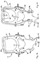
- perspektivisch den vorderen Endbereich des Fahrgestells eines Frontlenker-Lastkraftwagen (als Beispiel eines schweren Nutzfahrzeuges) mit der erfindungsgemäßen Starrachse samt Aufhängung, Federung und Dämpfung,
- Fig. 2
- den Fahrgestellbereich gemäß Fig. 1 in Ansicht von vorn,
- Fig. 3
- den Fahrgestellbereich gemäß Fig. 1 in Seitenansicht,
- Fig. 4
- die Darstellung gemäß Fig. 2 ohne Federbeine,
- Fig. 5
- die Darstellung gemäß Fig. 1 ohne Federbeine,
- Fig. 6
- die Darstellung gemäß Fig. 3 ohne Federbeine,
- Fig. 7
- die Darstellung gemäß Fig. 4 in Draufsicht ohne Panhardstab,
- Fig. 8
- den Starrachskörper-Längslenker-Verbund aus den Fig. 1 bis 7 in perspektivischer Alleindarstellung,
- Fig. 9
- einen Längslenker aus dem Starrachskörper-Längslenker-Verbund gemäß Fig. 8 in perspektivischer Alleindarstellung,
- Fig. 10
- den erfindungsgemäßen U-förmigen Querträger in vorderansichtiger Alleindarstellung,
- Fig. 11
- den erfindungsgemäßen Querträger in perspektivischer Alleindarstellung,
- Fig. 12 bis 17
- je eine unterschiedliche Ansicht des einen der beiden Federbeinhalter aus dem erfindungsgemäßen Querträger,
- Fig. 18 bis 23
- je eine unterschiedliche Ansicht des anderen der beiden Federbeinhalter aus dem erfindungsgemäßen Querträger.
- Fig. 1
- in perspective the front end area of the chassis of a front-steering truck (as an example of a heavy commercial vehicle) with the rigid axle according to the invention, including suspension, suspension and damping,
- Fig. 2
- 1 in front view,
- Fig. 3
- 1 in side view,
- Fig. 4
- 2 without struts,
- Fig. 5
- 1 without struts,
- Fig. 6
- 3 without struts,
- Fig. 7
- 4 in plan view without Panhard rod,
- Fig. 8
- the rigid axle body-trailing arm assembly of FIGS. 1 to 7 in a perspective view alone,
- Fig. 9
- 6 shows a trailing arm made of the rigid axle-trailing arm assembly according to FIG. 8 in a perspective representation on its own,
- Fig. 10
- the U-shaped cross member according to the invention in front view alone,
- Fig. 11
- the cross member according to the invention in a perspective sole representation,
- 12 to 17
- a different view of one of the two strut holders from the cross member according to the invention,
- 18 to 23
- each a different view of the other of the two strut holders from the cross member according to the invention.
Das erfindungsgemäße Fahrgestell ist Bestandteil eines schweren Nutzfahrzeuges, bei dem es sich um einen Lastkraftwagen, insbesondere der Frontlenker-Bauart mit kippbarem Fahrerhaus, mit An- und Aufbauten der verschiedensten Art, auch solche für Spezialeinsatzzwecke, eine Sattelzugmaschine oder um einen Omnibus handeln kann. Die erfindungsgemäße Starrachse kann als Vorderachse, Nachlaufachse oder Vorlaufachse mit lenkbaren oder nicht-lenkbaren Rädern zur Anwendung kommen. In der Zeichnung ist als Beispiel für die erfindungsgemäße Starrachse eine Vorderachse aufgezeigt. Vom Fahrgestell sind in der Zeichnung als Teile des Rahmens dessen beide Längsträger mit 1 und 2 bezeichnet.The chassis according to the invention is part of a heavy commercial vehicle, which is a truck, especially the front-link design tilting cab, with attachments and superstructures of various types, including those trade for special purposes, a tractor unit or an omnibus can. The rigid axle according to the invention can be used as a front axle, trailing axle or Leading axle with steerable or non-steerable wheels are used. In the drawing, a front axle is an example of the rigid axle according to the invention shown. From the chassis are in the drawing as parts of the frame whose two side members are labeled 1 and 2.
Die dargestellte Starrachse besteht einschließlich aller Aufhängungs-, Federungs- und
Dämpfungsorgane aus folgenden Hauptteilen, nämlich einem Starrachskörper 3,
einem linken Längslenker 4 und rechten Längslenker 5, einem linken Federbein 6
mit Luft- oder Schraubenfeder 7 und hierzu koaxialem Stoßdämpfer 8, einem rechten
Federbein 9 mit Luft- oder Schraubenfeder 10 und hierzu koaxialem Stoßdämpfer
11, einem Panhardstab 15 und einem - von vorne gesehen - U-förmigen Querträger
38, der sich aus einem linken Federbeinhalter 12, einem rechten Federbeinhalter
13 und einer Quertraverse 14 zusammensetzt.The rigid axle shown includes all suspension, suspension and
Damping elements from the following main parts, namely a
In der Zeichnung sind ein linker Multifunktionslagerschild mit 16 und ein rechter
Multifunktionslagerschild mit 17 bezeichnet. Jeder derselben ist außen an einem
Rahmen-Längsträger 1 bzw. 2 befestigt und dient zur rahmenseitigen Anlenkung der
erfindungsgemäßen Starrachse und im vorliegenden Beispiel darüber hinaus auch
als Halte-, Stütz- und Lagerorgan für eine größere Anzahl anzubauender Fahrzeugteile. In the drawing are a left multifunction bearing plate with 16 and a right one
Multifunction bearing plate labeled 17. Each of them is outside on one
Die erfindungsgemäße Starrachse bringt ihre Vorteile dann besonders zur Geltung,
wenn sie - wie dargestellt - nach Art einer selbststabilisierenden Verbundlenkerachse
ausgebildet ist. In diesem Fall ist die Starrachse grundsätzlich derart konstruiert,
daß zu ihrer Querführung nur der Panhardstab 15 notwendig ist und sie ohne den
bisher bei schweren Nutzfahrzeugen zur Beschränkung des Wankens notwendigen
U-förmigen Stabilisator auskommt, aber dessen Funktion einem Bauteilverbund aufgeprägt
ist, der sich aus dem Starrachskörper 3 und den beiden an diesem befestigten
Längslenkern 4, 5 zusammengesetzt. Dieser Zweckbestimmung und Funktion
gehorchend ist der Starrachskörper 3 in einem geraden Mittelbereich 18 zwischen
den beiden an ihm angeschlossenen Längslenkern 4, 5 definiert torsionsfähig ausgebildet.
Der je nach Anwendungsfall durchgehend gerade oder - wie in der Zeichnung
dargestellt - nach Art einer gekröpften Faustachse ausgebildete Starrachskörper
3 wird durch Schmieden oder Gießen hergestellt und anschließend an bestimmten
Stellen spanabhebend nach- bzw. endbearbeitet. Das Profil und die Größe des
Querschnitts seines Mittelbereiches 18 werden im Sinne der gewünschten Torsionsfähigkeit
auf den jeweiligen fahrzeugspezifischen Anwendungsfall abgestimmt. Am
Übergangsbereich zwischen geradem Mittelbereich 18 und jedem beiderseits desselben
anschließenden, im dargestellten Beispiel hochgekröpften Endabschnitt 19
bzw. 20 ist stirnseitig - im Fall einer gezogenen Achse vorne und im Fall einer geschobenen
Achse hinten - am Starrachskörper 3 jeweils ein Ansatz bzw. Vorsprung
mit nachbearbeiteter Anlagefläche 21 bzw. 22 mitangeformt, an der jeweils einer der
beiden Längslenker 4, 5 mit seinen achskörperseitigen Fuß 23 bzw. 24 kraftschlüssig
und gegebenenfalls auch noch formschlüssig angeflanscht ist. Die Anlagefläche
21 bzw. 22 erstreckt sich dabei mit großer Breite vorzugsweise über die ganze
am Starr-achskörper 3 verfügbare Höhe, um am Starrachskörper 3 eine möglichst
große Anschlußbasis für den jeweiligen Längslenker 4 bzw. 5 bereitzustellen. Zur
Befestigung sind je Längslenker 4, 5 mehrere Schrauben 25, z. B. je 4 Stück, vorgesehen,
die von der gegenüberliegenden Seite des Starrachskörpers 3 her durch in
diesem ausgebildete Durchgangsbohrungen hindurchgeführt sowie in hierzu fluchtende
Sacklochgewindebohrungen im jeweiligen Längslenker-Fuß 23 bzw 24 eingeschraubt
sind, und zwar mit einer hohen Vorspannkraft und so gesichert, daß der
Starrachskörper-Längslenker-Verbund bei allen im Fahrbetrieb auftretenden Belastungen
einwandfrei erhalten bleibt. Wie der Starrachskörper 3 sind auch die beiden
Längslenker 4, 5 in die Stabilisatorfunktion eingebunden und dementsprechend
ausgebildet. Die beiden jeweils als Gußteil, gegebenenfalls auch Schmiedeteil hergestellten
und anschließend an bestimmten Stellen spanabhebend nach- bzw. endbearbeiteten
Längslenker 4, 5 sind demzufolge in der Vertikalen vergleichsweise
biegesteif, um ihre Längsachse aber begrenzt tordierbar ausgebildet. Generell sind
die beiden Längslenker 4, 5 in diesem Fall hinsichtlich ihrer Biegesteifigkeit und
Torsionsfähigkeit auf den Gesamtstabilisierungseffekt in Verbindung mit dem torsionsfähigen
Starrachskörper 3 abgestimmt, und zwar über entsprechende Bemessung
und Formgebung ihrer Querschnitte. Im dargestellten Beispiel weist jeder der
beiden gleich langen Längslenker 4, 5 zwischen seinem Fuß 23 bzw. 24 und einem
andern-endes vorhandenen Lagerauge 26 bzw. 27 einen stabförmigen Bereich mit
einem sich über die Länge größenmäßig ändernden, zu dem Lagerauge 26 bzw. 27
hin kleiner werdenden Querschnitt auf. Zu dem besagten Gesamtstabilisierungseffekt
trägt außerdem bei, daß die beiden Längslenker 4, 5 zur Fahrzeuglängsmittelachse
spiegelsymmetrisch und - von oben betrachtet - derart gepfeilt zueinander
stehend am Starrachskörper 3 angeschlossen sind, daß sie eine Trapezfläche einschließen,
wobei der Abstand ihrer Lageraugen 26 bzw. 27, mit denen sie jeweils an
den rahmenfest angebrachten Multifunktionslagerschilden 16 bzw. 17 angelenkt
sind, kleiner ist als der Abstand ihrer achskörperseitigen Füße 23 bzw. 24. Wenn die
erfindungsgemäße Starrachse in das Fahrzeug eingebaut ist, verlaufen die beiden
Längslenker 4, 5 - von der Seite her betrachtet - vom Starrachskörper 3 ausgehend
schräg nach oben gerichtet zu den rahmenseitigen Multfunktionslageschilden 16
bzw. 17 hin.The rigid axle according to the invention then brings out its advantages in particular,
if - as shown - in the manner of a self-stabilizing torsion beam axle
is trained. In this case, the rigid axle is basically designed
that only the
Mir der erfindungsgemäßen Starrachse läßt sich im Fahrbetrieb ein für ein Nutzfahrzeug
sehr hoher Fahr- und Federungskomfort erzielen. Dieser erreicht ein Optimum,
wenn die größtmögliche Federspur festgelegt ist, das heißt, jedes der beiden Federbeine
6 bzw. 9 an seinem unteren Ende z. B. über ein in ein dortiges Lagerauge 28
bzw. 29 eingebautes Pratzengelenk 30 bzw. 31 an einer achskörperfesten Lagerstelle
angelenkt ist, die räumlich im Bereich zwischen einem Längslenker 4 bzw. 5 und
einem benachbarten achskörperendigen Radträger-Anschlußkopf 34 bzw. 35 so weit
wie möglich zu letzterem hin gerückt angeordnet und jeweils durch einen am Starrachskörper
3 angebauten oder mitangeformten maulartigen Bock 32 bzw. 33 gebildet
ist. Zu diesem hohen Fahr- und Federungskomfort trägt auch bei, daß die beiden
Federbeine 6 bzw. 9 - von vorne gesehen - gepfeilt zueinander eingebaut sind, derart,
daß ihre oberen Enden 36 bzw. 37 weniger weit voneinander beabstandet sind
als ihre untenendigen Lageraugen 28 bzw. 29. Von der Seite her gesehen steht jedes
Federbein 6 bzw. 9 entweder vertikal oder, je nach dem, ob es sich um eine geschobene
oder - wie dargestellt - gezogene Starrachse handelt, leicht nach vorn
oder hinten geneigt.With the rigid axle according to the invention, one can drive a commercial vehicle
achieve very high driving and suspension comfort. This reaches an optimum
when the largest possible spring track is determined, that is, each of the two
Mit seinem oberen Ende 36 bzw. 37 ist jedes Federbein 6 bzw. 9 räumlich oberhalb
und seitlich außerhalb des benachbarten Rahmenlängsträgers 1 bzw. 2 an einem
der beiden Federbeinhalter 12 bzw. 13 abgestützt und befestigt. Die beiden Federbeinhalter
12 bzw. 13 bilden erfindungsgemäß zusammen mit der Quertraverse 14
den - von vorne gesehen - U-förmigen Querträger 38, der mit seiner Quertraverse 14
den Starrachskörper 3 und den Panhardstab 15 oben mit geringem Abstand dachbildend
überbrückt und außerdem die beiden Rahmen-Längsträger 1, 2 stabilisierend
miteinander verbindet.With its
Innerhalb des Querträgers 38 ist die Quertraverse 14 durch ein im Querschnitt hutförmiges
Blechpreßteil, gegebenenfalls auch Schmiede- oder Gußteil, gebildet, das
einen geraden Mittelabschnitt 39 und beiderseits desselben je einen schräg hochgezogenen
Endabschnitt 40 bzw. 41 aufweist. Dessen äußere Enden sind nach Art
eines Maules ausgebildet, mit dem der anzuschließende Federbeinhalter 12 bzw. 13
außen übergriffen wird. Jedes Maul wird durch einen Ausschnitt 42 bzw. 43 im
Obergurt der Quertraverse 14 und beiderseits jedes Ausschnitts 42 bzw. 43 verbleibende
Wangen 44, 45 bzw. 46, 47 gebildet, denen am jeweiligen Federbeinhalter 12
bzw. 13 vorn und hinten zugehörige Anlageflächen 48, 49 bzw. 50, 51 zugeordnet
sind. Im Bereich dieser Anlageflächen 48, 49 bzw. 50, 51 ist die Quertraverse 14 mit
ihren Wangen 44, 45 bzw. 46, 47 abgestützt und dort durch entsprechende Bohrungen
bzw. Löcher 52 durchdringende Schrauben 53 mit dem jeweiligen Federbeinhalter
12 bzw. 13 fest verbunden. In der Mitte seines Obergurtes kann die Quertraverse
14 zur Gewichtsreduzierung einen oder mehrere Durchbrüche aufweisen.Within the
Die beiden Federbeinhalter 12 bzw. 13 sind vorzugsweise jeweils durch ein Stahlgußteil
realisiert, das nach dem Abguß an erforderlichen Stellen spanabhebend
nach - bzw. endbearbeitet wird. Jeder Federbeinhalter 12 bzw. 13 ist dabei, was seine
Form anbelangt, zumindest in seinem oberen Bereich nach Art einer nach außen
offenen Halbschale 54 bzw. 55 ausgebildet, von deren Begrenzungswand 56
bzw. 57 das zugehörige Federbein 6 bzw. 9 im Bereich seiner Luft- oder Schraubenfeder
7 bzw. 10 radial außen mit geringem Abstand von innen her partiell überdeckt
wird und an deren Kopfplatte 58 bzw. 59 das jeweilige Federbein 6 bzw. 9 obenendig
abgestützt und mittels je zwei Löcher 60 bzw. 61 durchdringenden Verschraubungen
62 bzw. 63 befestigt ist. Ein Zentralloch 64 bzw. 65 in der Federbein-Kopfplatte
58 bzw. 59 dient zur Zentrierung des jeweiligen Federbeines 12 bzw. 13
und freien Durchtritt von dessen oberem Ende 36 bzw. 37. Etwa in seinem mittleren
Höhen-Bereich weist jeder Federbeinhalter 12 bzw. 13 außenseitig an der Halbschale
54 bzw. 55 anschließend einen Anschlußflansch 66 bzw. 67 mit mehreren
Schraubenlöchern 68 bzw. 69 auf. Mit den jeweiligen Anschlußflansch 66 bzw. 67,
der etwa im Schubmittelpunkt gegeben ist, ist jeder der beiden Federbeinhalter 12
bzw. 13 außen am zugehörigen Rahmen-Längsträger 1 bzw. 2 angeflanscht und dort
jeweils mittels mehrerer die Löcher 68 bzw. 69 und hierzu längsträgerintern fluchtende
Löcher durchdringender Schrauben 70 mit zugehörigen Muttern befestigt.
Verschiedene Durchbrüche 71 bzw. 72 in den Federbeinhaltern 12 bzw. 13 dienen
zu deren Gewichtsreduzierung.The two
Einem der beiden Federbeinhalter 12 bzw. 13 ist über seine eigentliche Funktion
hinaus eine weitere Funktion aufgeprägt, nämlich jene, das Abstütz-, Halte- und Anlenkorgan
für das eine Ende des Panhardstabes 15 zu bilden. Zu diesem Zweck ist
der betreffende Federbeinhalter 12 bzw. 13 nach unten durch ein Lagerschild 73
verlängert, an dessen unterem Ende ein Maul und beiderseits desselben je ein Lagerauge
74 bzw. 75 ausgebildet sind, an denen der Panhardstab 15 über ein in sein
einenendiges Lagerauge 76 eingebautes Pratzengelenk 77 abstützt und mittels
Schrauben 78 befestigt ist.One of the two
Mit seinem anderen, gegenüberliegenden Ende ist der Panhardstab 15 z. B. über
ein in das dortige Lagerauge 79 eingebautes Pratzengelenk 80 an geeigneter Stelle
des Starrachskörper-Längslenker-Verbundes angelenkt. Für den Fall der Anlenkung
am Starrachskörper 3 ist an diesem ein Anschlußbock befestigt oder mitangeformt,
an dem eine entsprechende Anlagefläche und Gewindebohrungen für die Anschraubung
des Pratzengelenkes 80 angearbeitet sind. Im dargestellten Beispiel ist als
Anlenkstelle einer der beiden Längslenker 4 bzw. 5 gewählt. Demzufolge ist an diesem
ein seitlich nach innen vorspringender maulartiger Lagerbock 81 befestigt oder
- wie dargestellt - mitangeformt, der eine äußere stirnseitige Anlagefläche und zwei
interne Sackgewindelöcher für die Abstützung des Pratzengelenkes 80 und dessen
Befestigung mittels Schrauben 82 aufweist. Der als im wesentlichen gerader Stab
mit den endseitig angeschmiedeten Lageraugen 76, 79 ausgebildete Panhardstab
15 erstreckt sich aufgrund seiner wie vorstehend beschriebenen Anlenkung
annähernd parallel oder leicht schräg zum Mittelbereich 18 des Starrachskörpers 3
verlaufend.With its other, opposite end, the
Die beiden Multifunktionslagerschilde 16, 17 weisen jeweils einen zur Fahrzeugmitte
hin abragenden Vorsprung 83 bzw. 84 auf, in dessen von außen freiem Innenraum
eine Anlenkstelle für die Starrachse gegeben ist, und zwar in Form einer Anlagefläche
und einer Querbohrung 85, in die bei Montage ein das vordere Längslenker-Lagerauge
26 bzw. 27 durchdringender Lagerbolzen eingebaut und anschließend
jede dieser beiden Lagerstellen von außen her durch einen mittels mehrerer
Schrauben 86 am Multifunktionslagerschild 16 bzw. 17 befestigten Deckel 87 gesichert
wird.The two multifunction end shields 16, 17 each have one towards the center of the
Claims (12)
Applications Claiming Priority (2)
| Application Number | Priority Date | Filing Date | Title |
|---|---|---|---|
| DE19809268A DE19809268A1 (en) | 1998-03-04 | 1998-03-04 | Chassis of a heavy commercial vehicle |
| DE19809268 | 1998-03-04 |
Publications (2)
| Publication Number | Publication Date |
|---|---|
| EP0940323A1 true EP0940323A1 (en) | 1999-09-08 |
| EP0940323B1 EP0940323B1 (en) | 2003-05-07 |
Family
ID=7859706
Family Applications (1)
| Application Number | Title | Priority Date | Filing Date |
|---|---|---|---|
| EP99101609A Expired - Lifetime EP0940323B1 (en) | 1998-03-04 | 1999-02-03 | Chassis for a heavy-duty utility vehicle |
Country Status (2)
| Country | Link |
|---|---|
| EP (1) | EP0940323B1 (en) |
| DE (2) | DE19809268A1 (en) |
Cited By (3)
| Publication number | Priority date | Publication date | Assignee | Title |
|---|---|---|---|---|
| EP2363336A1 (en) * | 2010-03-02 | 2011-09-07 | Iveco Magirus Ag | Chassis of a forward control truck with a tiltable cab |
| US10577024B2 (en) * | 2018-06-25 | 2020-03-03 | Honda Motor Co., Ltd. | Bracket and mounting system for use in supporting a module within a vehicle |
| WO2022060648A1 (en) | 2020-09-17 | 2022-03-24 | Trova Commercial Vehicles Inc | Frame cross member for battery electric vehicle |
Families Citing this family (1)
| Publication number | Priority date | Publication date | Assignee | Title |
|---|---|---|---|---|
| KR100764485B1 (en) * | 2005-12-12 | 2007-10-08 | 현대자동차주식회사 | Support beam for vehicle |
Citations (6)
| Publication number | Priority date | Publication date | Assignee | Title |
|---|---|---|---|---|
| US4168086A (en) * | 1977-08-01 | 1979-09-18 | Dana Corporation | Radius arm support for a driving axle |
| DE4226500A1 (en) * | 1992-08-11 | 1994-02-17 | Daimler Benz Ag | Welded joint between profiled metal components at right angles - has flanges of channel-section cross-member joined at ends to form frames welded to hollow profiled members all around edges |
| EP0636531A2 (en) * | 1993-07-27 | 1995-02-01 | Nissan Motor Co., Ltd. | Vehicle structure |
| EP0678405A2 (en) * | 1994-04-18 | 1995-10-25 | Mercedes-Benz Ag | Bus front section comprising a carrier beam for resilient suspensions |
| US5641181A (en) * | 1995-03-23 | 1997-06-24 | Ford Motor Company | Cross member for a vehicle having rack and pinion steering |
| DE19624242A1 (en) * | 1996-06-18 | 1997-09-18 | Daimler Benz Ag | Vehicle front wheel suspension with rigid axle |
Family Cites Families (6)
| Publication number | Priority date | Publication date | Assignee | Title |
|---|---|---|---|---|
| FR1226451A (en) * | 1959-01-13 | 1960-07-13 | Simca Automobiles Sa | Subframe for motor vehicle |
| US4386792A (en) * | 1978-10-04 | 1983-06-07 | Ford Motor Company | Fabricated load support structural member |
| FR2662118A1 (en) * | 1990-05-17 | 1991-11-22 | Peugeot | REAR TRAIN OF A MOTOR VEHICLE. |
| JP3079791B2 (en) * | 1992-09-11 | 2000-08-21 | 日産自動車株式会社 | Axle beam suspension structure for vehicles |
| US5636857A (en) * | 1995-03-06 | 1997-06-10 | Ford Motor Company | Vehicle solid axle front suspension system |
| DE4329862A1 (en) * | 1993-09-03 | 1995-03-09 | Hotzenblitz Mobile Gmbh Co Kg | Rear axle for motor vehicles |
-
1998
- 1998-03-04 DE DE19809268A patent/DE19809268A1/en not_active Withdrawn
-
1999
- 1999-02-03 EP EP99101609A patent/EP0940323B1/en not_active Expired - Lifetime
- 1999-02-03 DE DE59905387T patent/DE59905387D1/en not_active Expired - Lifetime
Patent Citations (6)
| Publication number | Priority date | Publication date | Assignee | Title |
|---|---|---|---|---|
| US4168086A (en) * | 1977-08-01 | 1979-09-18 | Dana Corporation | Radius arm support for a driving axle |
| DE4226500A1 (en) * | 1992-08-11 | 1994-02-17 | Daimler Benz Ag | Welded joint between profiled metal components at right angles - has flanges of channel-section cross-member joined at ends to form frames welded to hollow profiled members all around edges |
| EP0636531A2 (en) * | 1993-07-27 | 1995-02-01 | Nissan Motor Co., Ltd. | Vehicle structure |
| EP0678405A2 (en) * | 1994-04-18 | 1995-10-25 | Mercedes-Benz Ag | Bus front section comprising a carrier beam for resilient suspensions |
| US5641181A (en) * | 1995-03-23 | 1997-06-24 | Ford Motor Company | Cross member for a vehicle having rack and pinion steering |
| DE19624242A1 (en) * | 1996-06-18 | 1997-09-18 | Daimler Benz Ag | Vehicle front wheel suspension with rigid axle |
Cited By (6)
| Publication number | Priority date | Publication date | Assignee | Title |
|---|---|---|---|---|
| EP2363336A1 (en) * | 2010-03-02 | 2011-09-07 | Iveco Magirus Ag | Chassis of a forward control truck with a tiltable cab |
| WO2011107455A1 (en) * | 2010-03-02 | 2011-09-09 | Iveco Magirus Ag | Chassis of a forward control truck with a tiltable cab |
| CN102811898A (en) * | 2010-03-02 | 2012-12-05 | 依维柯马基路斯公司 | Chassis of a forward control truck with a tiltable cab |
| CN102811898B (en) * | 2010-03-02 | 2015-09-16 | 依维柯马基路斯公司 | The forward with tiltable operator's compartment controls the chassis of truck |
| US10577024B2 (en) * | 2018-06-25 | 2020-03-03 | Honda Motor Co., Ltd. | Bracket and mounting system for use in supporting a module within a vehicle |
| WO2022060648A1 (en) | 2020-09-17 | 2022-03-24 | Trova Commercial Vehicles Inc | Frame cross member for battery electric vehicle |
Also Published As
| Publication number | Publication date |
|---|---|
| EP0940323B1 (en) | 2003-05-07 |
| DE19809268A1 (en) | 1999-09-09 |
| DE59905387D1 (en) | 2003-06-12 |
Similar Documents
| Publication | Publication Date | Title |
|---|---|---|
| EP0940272B1 (en) | Chassis for a cab-over-engine lorry | |
| DE102013108695B4 (en) | Subframe for a motor vehicle axle | |
| EP2155508B1 (en) | Rear axle for a motor vehicle | |
| DE102004028161B4 (en) | Underride protection for passenger vehicles for arrangement under the longitudinal beam level in front of a subframe or axle as an additional Crashebene | |
| WO2007031060A1 (en) | Front-axle bracket, in particular for motor vehicles | |
| EP1637438B1 (en) | Utility vehicle, particularly a rubbish collection or council vehicle, with a low-entry cab | |
| EP1318064B1 (en) | Modular chassis for a truck | |
| DE102009042060A1 (en) | Structural component for the rear frame structure of a motor vehicle | |
| EP0798198B1 (en) | Front bearing for tilt cab truck | |
| EP0940320B1 (en) | Chassis for a heavy-duty utility vehicle | |
| EP0940319B1 (en) | Chassis of a heavy utility vehicle | |
| WO2014009320A1 (en) | Wheel suspension connecting rod and axle assembly for a non-driven axle of a vehicle, particularly of a commercial vehicle | |
| EP0940325B1 (en) | Chassis for a heavy-duty utility vehicle | |
| EP0940322B1 (en) | Chassis for a heavy-duty utility vehicle | |
| EP0940324B1 (en) | Chassis for a heavy-duty utility vehicle | |
| EP0940323B1 (en) | Chassis for a heavy-duty utility vehicle | |
| EP2780182B1 (en) | Rigid axle with air suspension | |
| EP0940321B1 (en) | Chassis for a heavy-duty utility vehicle | |
| EP3095624A1 (en) | Axle assembly | |
| DE102015004858A1 (en) | Handlebar for rigid axles of commercial vehicles | |
| EP0502311B1 (en) | Axle with steered wheels and pneumatic suspension for a motor vehicle | |
| EP1447247B1 (en) | Rigid axle suspension for a vehicle | |
| DE102018006572B4 (en) | Vehicle suspension arrangement for at least one wheel axle | |
| EP0591719B1 (en) | Commercial vehicle, especially a cab over lorry engine | |
| DE102005003936A1 (en) | Chassis frame for commercial vehicle has spring strut support constructed as U-form spring strut bridge which fits over cut-out provided in longitudinal beam in to form part of upper edge fiber of longitudinal beam |
Legal Events
| Date | Code | Title | Description |
|---|---|---|---|
| PUAI | Public reference made under article 153(3) epc to a published international application that has entered the european phase |
Free format text: ORIGINAL CODE: 0009012 |
|
| 17P | Request for examination filed |
Effective date: 19990714 |
|
| AK | Designated contracting states |
Kind code of ref document: A1 Designated state(s): DE FR IT NL SE |
|
| AX | Request for extension of the european patent |
Free format text: AL;LT;LV;MK;RO;SI |
|
| AKX | Designation fees paid |
Free format text: DE FR IT NL SE |
|
| 17Q | First examination report despatched |
Effective date: 20010716 |
|
| GRAG | Despatch of communication of intention to grant |
Free format text: ORIGINAL CODE: EPIDOS AGRA |
|
| GRAG | Despatch of communication of intention to grant |
Free format text: ORIGINAL CODE: EPIDOS AGRA |
|
| GRAH | Despatch of communication of intention to grant a patent |
Free format text: ORIGINAL CODE: EPIDOS IGRA |
|
| GRAH | Despatch of communication of intention to grant a patent |
Free format text: ORIGINAL CODE: EPIDOS IGRA |
|
| GRAA | (expected) grant |
Free format text: ORIGINAL CODE: 0009210 |
|
| AK | Designated contracting states |
Designated state(s): DE FR IT NL SE |
|
| REF | Corresponds to: |
Ref document number: 59905387 Country of ref document: DE Date of ref document: 20030612 Kind code of ref document: P |
|
| REG | Reference to a national code |
Ref country code: SE Ref legal event code: TRGR |
|
| ET | Fr: translation filed | ||
| PLBE | No opposition filed within time limit |
Free format text: ORIGINAL CODE: 0009261 |
|
| STAA | Information on the status of an ep patent application or granted ep patent |
Free format text: STATUS: NO OPPOSITION FILED WITHIN TIME LIMIT |
|
| 26N | No opposition filed |
Effective date: 20040210 |
|
| REG | Reference to a national code |
Ref country code: NL Ref legal event code: TD Effective date: 20110420 |
|
| REG | Reference to a national code |
Ref country code: FR Ref legal event code: CD |
|
| REG | Reference to a national code |
Ref country code: DE Ref legal event code: R081 Ref document number: 59905387 Country of ref document: DE Owner name: MAN TRUCK & BUS AG, DE Free format text: FORMER OWNER: MAN NUTZFAHRZEUGE AG, 80995 MUENCHEN, DE Effective date: 20110518 |
|
| REG | Reference to a national code |
Ref country code: FR Ref legal event code: PLFP Year of fee payment: 18 |
|
| REG | Reference to a national code |
Ref country code: FR Ref legal event code: PLFP Year of fee payment: 19 |
|
| REG | Reference to a national code |
Ref country code: FR Ref legal event code: PLFP Year of fee payment: 20 |
|
| PGFP | Annual fee paid to national office [announced via postgrant information from national office to epo] |
Ref country code: NL Payment date: 20180223 Year of fee payment: 20 |
|
| PGFP | Annual fee paid to national office [announced via postgrant information from national office to epo] |
Ref country code: SE Payment date: 20180227 Year of fee payment: 20 Ref country code: IT Payment date: 20180221 Year of fee payment: 20 Ref country code: FR Payment date: 20180227 Year of fee payment: 20 |
|
| PGFP | Annual fee paid to national office [announced via postgrant information from national office to epo] |
Ref country code: DE Payment date: 20180430 Year of fee payment: 20 |
|
| REG | Reference to a national code |
Ref country code: DE Ref legal event code: R071 Ref document number: 59905387 Country of ref document: DE |
|
| REG | Reference to a national code |
Ref country code: NL Ref legal event code: MK Effective date: 20190202 |
|
| REG | Reference to a national code |
Ref country code: SE Ref legal event code: EUG |