EP1500466B9 - Device for alternately machining a workpiece - Google Patents
Device for alternately machining a workpiece Download PDFInfo
- Publication number
- EP1500466B9 EP1500466B9 EP20030016425 EP03016425A EP1500466B9 EP 1500466 B9 EP1500466 B9 EP 1500466B9 EP 20030016425 EP20030016425 EP 20030016425 EP 03016425 A EP03016425 A EP 03016425A EP 1500466 B9 EP1500466 B9 EP 1500466B9
- Authority
- EP
- European Patent Office
- Prior art keywords
- grinding wheel
- electrode segment
- electroerosion electrode
- groove
- electroerosion
- Prior art date
- Legal status (The legal status is an assumption and is not a legal conclusion. Google has not performed a legal analysis and makes no representation as to the accuracy of the status listed.)
- Expired - Lifetime
Links
- 238000003754 machining Methods 0.000 title claims description 14
- 238000000034 method Methods 0.000 claims description 10
- 230000008569 process Effects 0.000 claims description 9
- 230000003628 erosive effect Effects 0.000 claims description 8
- 230000033001 locomotion Effects 0.000 claims description 5
- 230000001681 protective effect Effects 0.000 claims description 4
- 238000005520 cutting process Methods 0.000 claims description 3
- 230000000694 effects Effects 0.000 claims 1
- 238000009760 electrical discharge machining Methods 0.000 description 39
- 230000003993 interaction Effects 0.000 description 2
- 239000000853 adhesive Substances 0.000 description 1
- 230000001070 adhesive effect Effects 0.000 description 1
- 230000005540 biological transmission Effects 0.000 description 1
- 230000008859 change Effects 0.000 description 1
- 238000009413 insulation Methods 0.000 description 1
- 239000000463 material Substances 0.000 description 1
- 230000002441 reversible effect Effects 0.000 description 1
- 239000011343 solid material Substances 0.000 description 1
- 230000007480 spreading Effects 0.000 description 1
- 238000003892 spreading Methods 0.000 description 1
- 238000003860 storage Methods 0.000 description 1
- 239000000758 substrate Substances 0.000 description 1
Images


Classifications
-
- B—PERFORMING OPERATIONS; TRANSPORTING
- B23—MACHINE TOOLS; METAL-WORKING NOT OTHERWISE PROVIDED FOR
- B23H—WORKING OF METAL BY THE ACTION OF A HIGH CONCENTRATION OF ELECTRIC CURRENT ON A WORKPIECE USING AN ELECTRODE WHICH TAKES THE PLACE OF A TOOL; SUCH WORKING COMBINED WITH OTHER FORMS OF WORKING OF METAL
- B23H5/00—Combined machining
- B23H5/10—Electrodes specially adapted therefor or their manufacture
-
- B—PERFORMING OPERATIONS; TRANSPORTING
- B23—MACHINE TOOLS; METAL-WORKING NOT OTHERWISE PROVIDED FOR
- B23H—WORKING OF METAL BY THE ACTION OF A HIGH CONCENTRATION OF ELECTRIC CURRENT ON A WORKPIECE USING AN ELECTRODE WHICH TAKES THE PLACE OF A TOOL; SUCH WORKING COMBINED WITH OTHER FORMS OF WORKING OF METAL
- B23H1/00—Electrical discharge machining, i.e. removing metal with a series of rapidly recurring electrical discharges between an electrode and a workpiece in the presence of a fluid dielectric
- B23H1/04—Electrodes specially adapted therefor or their manufacture
-
- B—PERFORMING OPERATIONS; TRANSPORTING
- B23—MACHINE TOOLS; METAL-WORKING NOT OTHERWISE PROVIDED FOR
- B23H—WORKING OF METAL BY THE ACTION OF A HIGH CONCENTRATION OF ELECTRIC CURRENT ON A WORKPIECE USING AN ELECTRODE WHICH TAKES THE PLACE OF A TOOL; SUCH WORKING COMBINED WITH OTHER FORMS OF WORKING OF METAL
- B23H5/00—Combined machining
- B23H5/04—Electrical discharge machining combined with mechanical working
-
- B—PERFORMING OPERATIONS; TRANSPORTING
- B23—MACHINE TOOLS; METAL-WORKING NOT OTHERWISE PROVIDED FOR
- B23H—WORKING OF METAL BY THE ACTION OF A HIGH CONCENTRATION OF ELECTRIC CURRENT ON A WORKPIECE USING AN ELECTRODE WHICH TAKES THE PLACE OF A TOOL; SUCH WORKING COMBINED WITH OTHER FORMS OF WORKING OF METAL
- B23H9/00—Machining specially adapted for treating particular metal objects or for obtaining special effects or results on metal objects
- B23H9/08—Sharpening
-
- B—PERFORMING OPERATIONS; TRANSPORTING
- B24—GRINDING; POLISHING
- B24B—MACHINES, DEVICES, OR PROCESSES FOR GRINDING OR POLISHING; DRESSING OR CONDITIONING OF ABRADING SURFACES; FEEDING OF GRINDING, POLISHING, OR LAPPING AGENTS
- B24B27/00—Other grinding machines or devices
- B24B27/0076—Other grinding machines or devices grinding machines comprising two or more grinding tools
-
- B—PERFORMING OPERATIONS; TRANSPORTING
- B24—GRINDING; POLISHING
- B24B—MACHINES, DEVICES, OR PROCESSES FOR GRINDING OR POLISHING; DRESSING OR CONDITIONING OF ABRADING SURFACES; FEEDING OF GRINDING, POLISHING, OR LAPPING AGENTS
- B24B3/00—Sharpening cutting edges, e.g. of tools; Accessories therefor, e.g. for holding the tools
- B24B3/34—Sharpening cutting edges, e.g. of tools; Accessories therefor, e.g. for holding the tools of turning or planing tools or tool bits, e.g. gear cutters
- B24B3/343—Sharpening cutting edges, e.g. of tools; Accessories therefor, e.g. for holding the tools of turning or planing tools or tool bits, e.g. gear cutters of throw-away cutting bits
-
- B—PERFORMING OPERATIONS; TRANSPORTING
- B24—GRINDING; POLISHING
- B24D—TOOLS FOR GRINDING, BUFFING OR SHARPENING
- B24D7/00—Bonded abrasive wheels, or wheels with inserted abrasive blocks, designed for acting otherwise than only by their periphery, e.g. by the front face; Bushings or mountings therefor
- B24D7/18—Wheels of special form
-
- H—ELECTRICITY
- H05—ELECTRIC TECHNIQUES NOT OTHERWISE PROVIDED FOR
- H05K—PRINTED CIRCUITS; CASINGS OR CONSTRUCTIONAL DETAILS OF ELECTRIC APPARATUS; MANUFACTURE OF ASSEMBLAGES OF ELECTRICAL COMPONENTS
- H05K3/00—Apparatus or processes for manufacturing printed circuits
- H05K3/0011—Working of insulating substrates or insulating layers
- H05K3/0044—Mechanical working of the substrate, e.g. drilling or punching
- H05K3/0052—Depaneling, i.e. dividing a panel into circuit boards; Working of the edges of circuit boards
Description
Die Erfindung betrifft eine Vorrichtung zum abwechselnden Bearbeiten eines Werkstückes mittels einer für einen Schleifvorgang in Rotation versetzbaren Schleifscheibe oder einer Funkenerosionselektrode, insbesondere zur Bearbeitung von Umfang und Schutzfase an PKD- und PKB-Schneidplatten, wobei die Funkenerosionselektrode als ein der Schleifscheibe in der Form zumindest in etwa angepasstes, für den Erodiervorgang auf die Schleifscheibe wiederabnehmbar aufsetzbares und in eine Pendelbewegung versetzbares Funkenerosionselektrodensegment ausgebildet ist, das Funkenerosionselektrodensegment durch zumindest ein Halteelement , insbesondere eine Magnetbefestigung an der Schleifscheibe anbringbar ist und zur positionierten Anordnung des Funkenerosionselektrodensegmentes an der Schleifscheibe zumindest eine Positioniereinrichtung vorgesehen ist. Eine solche Vorrichtung ist aus der
Die Schneidplatten können dabei u. a. Vollmaterial und PKD/PKB-Einsätze auf Hartmetallsubstrat sein.The inserts can u. a. Solid material and PCD / PKB inserts on cemented carbide substrate.
Der Zweck solcher Vorrichtungen besteht darin, die Vorteile der Bearbeitungsverfahren Erodieren und Schleifen, nämlich hohe Abträge mit hoher Wirtschaftlichkeit bei geringem Verschleiß einerseits und hohe Bearbeitungsqualität und hohe Oberflächengüte bei geringem Schleifaufmaß andererseits zu kombinieren.The purpose of such devices is to erode and grind the advantages of the machining methods, namely high efficiency and low cost To combine wear on the one hand and high quality machining and high surface quality with low grinding allowance on the other hand.
Insofern wird in einem ersten Bearbeitungsschritt durch Erodieren das Werkstück in etwa auf die gewünschten Abmessungen gebracht und danach erfolgt durch Schleifen die Feinbearbeitung sowohl in Bezug auf die Form und Abmessungen als auch hinsichtlich der Oberflächengüte.In this respect, in a first processing step by eroding the workpiece is brought to about the desired dimensions and then done by grinding the fine machining both in terms of shape and dimensions and in terms of surface quality.
Es sind derartige Vorrichtungen bekannt, bei denen ein Funkenerosionselektrodensegment mittels zumeist mehrerer Positioniervorrichtungen und zumindest einer Befestigungseinrichtung, z. B. in Form eines magnetischen Befestigungselementes, an der Schleifscheibe angebracht und genau ausgerichtet angeordnet wird. Dabei sind die Positioniervorrichtungen stiftförmig ausgebildet und werden in entsprechende Ausnehmungen in der Schleifscheibe eingeführt.There are known such devices in which a spark erosion electrode segment by means of mostly a plurality of positioning devices and at least one fastening device, for. B. in the form of a magnetic fastener, attached to the grinding wheel and arranged accurately aligned. The positioning devices are pin-shaped and are inserted into corresponding recesses in the grinding wheel.
Nachteilig hierbei ist, dass bei einer solchen Zentrierung eine genaue Ausrichtung sowohl der Winkelstellung der Schleifscheibe als auch der relativen Position von Schleifscheibe und Funkenerosionselektrodensegment zueinander erforderlich ist. Insbesondere muss die Spindel vor Anfahren der Anbringungsposition neu referenziert und danach erst in die von der Referenzierungsposition üblicherweise abweichende Anbringungsposition gefahren werden, da die genaue Achsposition aufgrund des Schleifbetriebes nicht mehr bekannt ist, was z. B. auf einen Schlupf des Keilriemens o. dgl. zurückzuführen ist.The disadvantage here is that in such a centering an exact alignment of both the angular position of the grinding wheel and the relative position of the grinding wheel and EDM electrode segment to each other is required. In particular, the spindle must be referenced before approaching the attachment position and then moved to the usually deviating from the referencing attachment position, since the exact axis position due to the grinding operation is no longer known what z. B. on a slip of the V-belt o. The like. Is due.
Das Referenzieren stellt jedoch einen beachtlichen und vorzugsweise zu vermeidenden Zeitaufwand dar. Auch muss nach dem Referenzieren die Montageposition sehr genau angefahren werden, da die üblichen Positionierstifte sowie die zugeordnete Bohrung toleriert sind.However, referencing represents a considerable and preferably to be avoided expenditure of time. Also must After referencing the mounting position can be approached very accurately, since the usual positioning pins and the associated hole are tolerated.
Aufgabe der Erfindung ist es, die vorgenannten Nachteile zu vermeiden und eine Vorrichtung zum abwechselnden Bearbeiten eines Werkstückes anzugeben, mit der bei qualitativ hochwertigen Bearbeitungsergebnissen auch ein unkomplizierter und gut automatisierbarer und vor allem ohne hohen Zeitaufwand erfolgender Werkzeugwechsel möglich ist.The object of the invention is to avoid the aforementioned disadvantages and to provide a device for alternately machining a workpiece, with the high-quality machining results and an uncomplicated and easily automatable and above all without a high expenditure of time successful tool change is possible.
Diese Aufgabe wird gelöst durch eine Vorrichtung zum abwechselnden Bearbeiten eines Werkstückes mittels einer für einen Schleifvorgang in Rotation versetzbaren Schleifscheibe oder einer Funkenerosionselektrode, insbesondere zur Bearbeitung von Umfang und Schutzfase an PKD- und PKB-Schneidplatten, wobei die Funkenerosionselektrode als ein der Schleifscheibe in der Form zumindest in etwa angepasstes, für den Erodiervorgang auf die Schleifscheibe wiederabnehmbar aufsetzbares und in eine Pendelbewegung versetzbares Funkenerosionselektrodensegment ausgebildet ist, das Funkenerosionselektrodensegment durch zumindest ein Halteelement , insbesondere eine Magnetbefestigung an der Schleifscheibe anbringbar ist und zur positionierten Anordnung des Funkenerosionselektrodensegmentes an der Schleifscheibe zumindest eine Positioniereinrichtung vorgesehen ist. Hierbei umfasst die Positioniereinrichtung zumindest ein an dem Funkenerosionselektrodensegment oder an der Schleifscheibe vorgesehenes Positionierelement, welches eine positionierte Anbringung des Funkenerosionselektrodensegmentes zumindest in einem bestimmten Drehwinkelbereich der Schleifscheibe, insbesondere bei jedem beliebigem Drehwinkel der Schleifscheibe, ermöglicht, wobei das Positionierelement mit wenigstens einer sich zumindest über einen Teilbereich der Schleifscheibe oder des Funkenerosionselektrodensegmentes erstreckend ausgebildeten Kontaktfläche an der Schleifscheibe oder an dem Funkenerosionselektrodensegment ausrichtend zusammenwirkt.This object is achieved by a device for alternately machining a workpiece by means of a grinding wheel rotatable for a grinding operation or a spark erosion electrode, in particular for processing circumference and protective chamfer on PCD and PKB inserts, wherein the spark erosion electrode as one of the grinding wheel in the mold the spark erosion electrode segment can be attached to the grinding wheel by at least one holding element, in particular a magnetic attachment, and at least one positioning device is provided for the positioned arrangement of the spark erosion electrode segment on the grinding wheel is. In this case, the positioning device comprises at least one positioning element provided on the spark erosion electrode segment or on the grinding wheel, which permits a positioned attachment of the spark erosion electrode segment at least in a specific rotation angle range of the grinding wheel, in particular at any arbitrary angle of rotation of the grinding wheel, the positioning element having at least one at least over a portion of the grinding wheel or the spark erosion electrode segment extending formed contact surface on the grinding wheel or on the spark erosion electrode segment cooperating aligning.
Hierdurch kann ohne eine aufwendige genaue Positionierung des Drehwinkels der Schleifscheibenspindel das Funkenerosionselektrodensegment bei maximal grober Positionierung der Schleifscheibenspindel erfolgen. Die Spindel muss dann nur um einen bestimmten Winkelbetrag in die Arbeitsposition verfahren werden und kann dort eine gesteuerte Pendelbewegung ausführen. Nach erfolgtem Erodiervorgang wird die Spindel dann wieder in die Anbringposition zurückverfahren und das Funkenerosionselektrodensegment kann für die anschliessende Schleifbearbeitung abgenommen werden.As a result, the spark erosion electrode segment can be made with a maximum coarse positioning of the grinding wheel spindle without complex precise positioning of the angle of rotation of the grinding wheel spindle. The spindle must then be moved only by a certain angle in the working position and can perform there a controlled pendulum motion. After the erosion process, the spindle is then moved back into the mounting position and the spark erosion electrode segment can be removed for subsequent grinding.
Erfindungsgemäß kann das Positionierelement zumindest drei eine Ebene aufspannende Punktkontakte umfassen und die Kontaktfläche(n) in den Kontaktbereichen kann (können) so ausgebildet sein, dass die Auflagekräfte der Punktkontakte eine resultierende Flächennormale auf der von den Punktkontakten aufgespannten Ebene bilden.According to the invention, the positioning element may comprise at least three point contacts spanning a plane, and the contact surface (s) in the contact regions may be designed such that the bearing forces of the point contacts form a resulting surface normal on the plane spanned by the point contacts.
Dabei können die Punktkontakte durch zumindest teilweise herausragend angeordnete Kugeln gebildet sein. Es sind aber auch alternative Ausgestaltungen möglich.In this case, the point contacts may be formed by at least partially outstandingly arranged balls. But there are also alternative embodiments possible.
Vorzugsweise kann eine auf der Schleifscheibe zumindest teilweise umlaufende Nut mit radial zur Rotationsachse der Schleifscheibe ausgerichteter Nuttiefe die Kontaktfläche(n) bilden. Die Positionierelemente für die Punktkontakte können dabei als rechteckförmige Körper mit gerundeter Seitenkante ausgebildet sein, so dass aufgrund des Zusammenwirkens der Krümmung der Nut und des Radius der rechteckförmigen Körper ebenfalls Punktkontakte resultieren. Auch sind V-Profilplatten verwendbar.Preferably, a groove extending at least partially around the grinding wheel can form the contact surface (s) with a groove depth aligned radially with respect to the axis of rotation of the grinding wheel. The positioning elements for the point contacts can be used as a rectangular body with rounded Side edge may be formed so that due to the interaction of the curvature of the groove and the radius of the rectangular body also point contacts result. Also V-profile plates can be used.
Sofern die Nut umlaufend ausgebildet ist, entfällt das Anfahren einer Referenzposition hinsichtlich der Schleifscheibenspindel vollständig.If the groove is formed circumferentially, the start of a reference position with respect to the grinding wheel spindle completely eliminated.
Vorzugsweise kann die Nut außenseitig an der Schleifscheibe vorgesehen sein, so dass eine leichte Anbringung des Funkenerosionselektrodensegmentes von außen möglich ist.Preferably, the groove may be provided on the outside of the grinding wheel, so that an easy attachment of the spark erosion electrode segment from the outside is possible.
Dabei kann die Nut leicht geöffnet ausgebildete Nutflanken aufweisen, oder die Nut kann auch parallel oder hinterschnitten ausgebildete Nutflanken aufweisen.In this case, the groove may have slightly open groove flanks formed, or the groove may also have parallel or undercut formed groove flanks.
Selbstverständlich ist aber auch eine vertauschte Anordnung von Nut und die Punktkontakte bewirkenden Positionierelementen möglich.Of course, however, a reversed arrangement of groove and the point contacts causing positioning is possible.
Sofern wenigstens ein Halteelement als Klemmbefestigung ausgebildet ist, kann das Funkenerosionselektrodensegment alternativ oder zusätzlich zur Magnetbefestigung auch mechanisch in seiner Position gehalten sein.If at least one holding element is designed as a clamp fastening, the spark erosion electrode segment can alternatively or additionally be held mechanically in its position in addition to the magnetic fastening.
Dabei kann die Klemmbefestigung einen insbesondere gegen eine Rückstellkraft aufgespreizten und in dieser Position fixierten Klemmbereich beinhalten, der eine Befestigung in der Nut bewirkt.In this case, the clamp attachment include a particular spread against a restoring force and fixed in this position clamping area, which causes an attachment in the groove.
Die Aufspreizung des Klemmbereichs kann hierbei durch den Greifer einer Handhabungseinrichtung insbesondere durch das Vorspannen einer Feder bewirkbar und insbesondere durch das Lösen einer die Feder im vorgespannten Zustand haltenden Verriegelungsklinke oder dergleichen auch wieder rückgängig machbar sein, so dass eine gute Automatisierbarkeit des Montage- bzw. Demontagevorgangs des Funkenerosionselektrodensegmentes gegeben ist.The spreading of the clamping area can in this case by the gripper of a handling device in particular by the biasing of a spring effected and in particular by the release of a spring in the prestressed state holding locking pawl or the like also be reversible feasible, so that a good automation of the assembly and disassembly process of the spark erosion electrode segment is given.
Vorzugsweise kann das Funkenerosionselektrodensegment kreissegmentförmig ausgebildet sein, so dass eine in Bewegungsrichtung an die Schleifscheibenform angepasste Form des Funkenerosionselektrodensegmentes gegeben ist und mit einem geringen Materialaufwand eine ausreichend dimensionierte Bearbeitungsfläche erzielt wird.Preferably, the spark erosion electrode segment can be designed in the shape of a circle segment, so that a shape of the spark erosion electrode segment which is adapted to the grinding wheel shape in the direction of movement is given and a sufficiently large machining surface is achieved with a low material expenditure.
Auch kann das Funkenerosionselektrodensegment eine in etwa zylindermantelsegmentförmig ausgebildete Form aufweisen, so dass das Funkenerosionselektrodensegment an die Formgebung einer in etwa schüsselförmigen Schleifscheibe angepasst ist und somit die entsprechenden Bearbeitungsarten, wie z. B. das Erodieren des Umfangs und das Schleifen der Schutzfase an Schneidplatten o. dgl. möglich sind. Insofern können die Kontaktflächen von Schleifscheibe und Funkenerosionselektrodensegment gegeneinander elektrisch isoliert sein, so dass unabhängig vom technischen Aufbau der Bearbeitungsmaschine elektrische Probleme, insbesondere dadurch, dass die Schleifscheibe "unter Strom steht", von vornherein vermieden werden. Es ist aber auch eine Isolierung direkt an der Elektrode, d. h. zwischen Elektrode und Elektrodenhalter, möglich. Für die Stromübertragung zum Funkenerosionselektrodensegment kann dabei ein Kabel vorgesehen sein.Also, the spark erosion electrode segment may have an approximately cylinder-shell-segment-shaped shape, so that the spark erosion electrode segment is adapted to the shape of an approximately bowl-shaped grinding wheel and thus the corresponding processing types, such. As the erosion of the circumference and the grinding of Schutzfase to cutting inserts o. The like. Are possible. In this respect, the contact surfaces of grinding wheel and spark erosion electrode segment can be electrically isolated from each other, so that regardless of the technical structure of the machine electrical problems, in particular by the fact that the grinding wheel is "under power" avoided from the outset. But it is also an insulation directly on the electrode, d. H. between electrode and electrode holder, possible. For the power transmission to the spark erosion electrode segment can be provided a cable.
Bei einem bevorzugten Ausführungsbeispiel kann das Verschleißvolumen des Funkenerosionselektrodensegmentes zum zeitgleichen Austausch des Funkenerosionselektrodensegmentes mit der Schleifscheibe auf das Verschleißvolumen der Schleifscheibe abgestimmt sein, so dass unterschiedliche Austauschintervalle, und somit erhöhte Kosten und höhere Stillstandzeiten vermieden werden.In a preferred embodiment, the wear volume of the spark erosion electrode segment for simultaneous replacement of the spark erosion electrode segment with the grinding wheel to be matched to the wear volume of the grinding wheel, so that different exchange intervals, and thus increased costs and longer downtime can be avoided.
Eine Steuereinheit kann zur Regelung der Größe des Funkenspaltes zwischen Funkenerosionselektrodensegment und Werkstück vorgesehen und mit der Steuerung der für die Bearbeitung zuständigen Vorrichtung verbunden sein, so dass die Steuerung der Arbeitsparameter des Erodierens zumindest teilweise durch die Steuerung, insbesondere CNC-Steuerung der Vorrichtung erfolgen kann und hierdurch die z. B. entsprechende(n) Vorschubachse(n) angesteuert und verfahren wird (werden).A control unit may be provided for controlling the size of the spark gap between EDM electrode and workpiece and connected to the control of the device responsible for processing, so that the control of the working parameters of the erosion can be done at least partially by the controller, in particular CNC control of the device and thereby z. B. corresponding (n) feed axis (s) is controlled and moved (will).
Weiterhin kann für das Funkenerosionselektrodensegment eine seiner Arbeitsposition naheliegende, außerhalb des Wirkbereiches der Schleifscheibe befindliche und insbesondere gegenüber einer Schärfeinrichtung für die Schleifscheibe angeordnete Lager- und Ruheposition vorgesehen sein, so dass ein automatisiertes Auf- und Absetzen bzw. Anbringen des Funkenerosionselektrodensegmentes an der Schleifscheibe durch eine entsprechende Handhabungseinrichtung erfolgen kann und die Schleifscheibe bei in der Lager- und Ruheposition "geparkten" Funkenerosionselektrodensegment frei rotieren kann.Furthermore, for the spark erosion electrode segment a working position obvious, located outside the effective range of the grinding wheel and arranged in particular with respect to a sharpening device for the grinding wheel bearing and rest position may be provided so that an automated setting and setting or attaching the spark erosion electrode segment to the grinding wheel by a appropriate handling device can be done and the grinding wheel can rotate freely in the storage and rest position "parked" spark erosion electrode segment.
Im Folgenden werden in der Zeichnung dargestellte Ausführungsbeispiele der Erfindung erläutert. Es zeigen:
- Fig. 1
- ausschnittweise ein erstes Ausführungsbeispiel einer erfindungsgemäßer Vorrichtung in einer ersten Bearbeitungsposition,
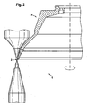
- Fig. 2
- den Gegenstand nach
Fig. 1 in einer zweiten Bearbeitungsposition und - Fig. 3
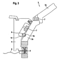
- einen Detailausschnitt aus
Fig. 1 in vergrößerter Darstellung mit aufgesetztem Funkenerosionselektrodensegment. - Fig. 4
- ausschnittweise ein zweites Ausführungsbeispiel einer erfindungsgemäßer Vorrichtung in Draufsicht,
- Fig. 5
- den Schnitt A-A des Gegenstandes nach
Fig. 4 , - Fig. 6
- den Schnitt B-B des Gegenstandes nach
Fig. 4 , - Fig. 7
- den Schnitt C-C des Gegenstandes nach
Fig. 4 , - Fig. 8
- eine teilweise Draufsicht auf den Gegenstandes nach
Fig. 6 und - Fig. 9
- das Detail Y des Gegenstandes nach
Fig. 6 .
- Fig. 1
- 1, a first embodiment of an inventive device in a first processing position,
- Fig. 2
- the object after
Fig. 1 in a second processing position and - Fig. 3
- a detail from
Fig. 1 in an enlarged view with attached spark erosion electrode segment. - Fig. 4
- 2 shows a detail of a second embodiment of an inventive device in plan view,
- Fig. 5
- the section AA of the object after
Fig. 4 . - Fig. 6
- the section BB of the object after
Fig. 4 . - Fig. 7
- the section CC of the object after
Fig. 4 . - Fig. 8
- a partial plan view of the object according to
Fig. 6 and - Fig. 9
- the detail Y of the object
Fig. 6 ,
In allen Figuren werden für gleiche bzw. gleichartige Bauteile übereinstimmende Bezugszeichen verwendet.In all figures the same reference numerals are used for identical or similar components.
Wie aus
Das Werkstück 2 ist während der Bearbeitung in eine Haltevorrichtung 5 klemmend gehalten, die eine Drehung des Werkstückes 2 um seine Mittelachse ermöglicht.The
Wie in
Die Nut 6a kann dabei nur in Teilbereichen der Schleifscheibe 3 vorgesehen sein, insbesondere aber auch umlaufend ausgebildet und vorzugsweise außenseitig an der Schleifscheibe 3 angeordnet sein.The
Die Kugeln 6 können dabei in Pendelrichtung gesehen voneinander beabstandet in verschiedene Bereiche einer Nut 6a eingreifen, es ist aber auch möglich, dass eine oder mehrere Kugeln 6 in eine zusätzlich vorgesehene andere Nut 6a (in der Zeichnung nicht dargestellt) eingreifen als mindestens zwei andere Kugeln 6.The
Die Kugeln 6 können dabei insbesondere mittels Klebetaschen 10 befestigt sein, es sind jedoch auch andere Befestigungsalternativen möglich.The
Wie in
Gemäß den
Claims (12)
- Apparatus (1) for the alternating machining of a workpiece (2) by means of a grinding wheel (3), which can be set in rotation for a grinding process, or by means of an electroerosion electrode, more especially for machining the periphery and protective chamfer of PKD and PKB cutting plates,- the electroerosion electrode being in the form of an electroerosion electrode segment (4) which is at least substantially adapted to the grinding wheel (3) in respect of configuration, is mountable, for the erosion process, on the grinding wheel (3) so as to be removable therefrom again, and can be set into a pendulum-type movement,- the electroerosion electrode segment (4) being attachable by at least one retaining member, more especially a magnet-type securement, to the grinding wheel (3), and- at least one positioning means being provided for the positioned disposition of the electroerosion electrode segment (4) on the grinding wheel (3),
characterised in that- the positioning means includes at least one positioning member, which is provided on the electroerosion electrode segment (4) or on the grinding wheel (3), and which permits a positioned attachment of the electroerosion electrode segment (4) at least in one specific angular range of rotation of the grinding wheel (3), more especially at any desirable angle of rotation of the grinding wheel (3),- the positioning member co-operating with at least one contact face, which is provided so as to extend at least over a partial region of the grinding wheel (3) or of the electroerosion electrode segment (4), on the grinding wheel (3) or on the electroerosion electrode segment (4) in an aligned manner. - Apparatus (1) according to claim 1, characterised in that the positioning member includes at least three point contacts, which span a plane, and the contact face(s) is (are) configured in the contact regions so that the forces of application of the point contacts form a resultant surface normal on the plane, which is spanned by the point contacts.
- Apparatus (1) according to claim 1 or 2, characterised in that the point contacts are formed by balls, which are disposed so as to protrude at least partially.
- Apparatus (1) according to one of claims 1 to 3, characterised in that a groove, which surrounds the grinding wheel (3) at least partially and has a groove depth orientated radially relative to the axis of rotation of the grinding wheel (3), forms the contact face(s).
- Apparatus (1) according to claim 4, characterised in that the groove (6a) has groove flanks with a slightly open configuration.
- Apparatus (1) according to claim 4, characterised in that the groove (6a) has groove flanks with a parallel or undercut configuration.
- Apparatus (1) according to one of claims 1 to 6, characterised in that at least one retaining member is in the form of a clamping securement.
- Apparatus (1) according to claim 7, insofar as it relates to one of claims 4 to 6, characterised in that the clamping securement includes a clamping region, more especially splayed-open in opposition to a restoring force and secured in this position, which clamping region effects a securement in the groove (6a).
- Apparatus (1) according to claim 8, characterised in that the splaying-open of the clamping region can be effected by the gripper of an operating means, more especially by the initial tensioning of a spring, and can be cancelled more especially by the release of a locking pawl or the like, which keeps the spring in its initially tensioned state.
- Apparatus (1) according to one of claims 1 to 9, characterised in that the electroerosion electrode segment (4) is in the form of a circular segment.
- Apparatus (1) according to one of claims 1 to 10, characterised in that the electroerosion electrode segment (4) has a configuration which is substantially in the form of a cylinder casing.
- Grinding wheel (3), formed from a concave-conical grinding wheel flange (3a) and a grinding wheel ring (3b) secured thereto, the grinding wheel (3) being provided for use in an apparatus (1) according to one of claims 1 to 11, and, in consequence, the grinding wheel (3) being designed for the alternating machining of a workpiece (2) by means of the grinding wheel (3), which can be set in rotation for a grinding process, or by means of an electroerosion electrode which is in the form of an electroerosion electrode segment (4), the grinding wheel (3), which is at least substantially adapted to the grinding wheel (3) in respect of configuration, and is mountable, for the erosion process, on the grinding wheel (3) so as to be removable therefrom again, so that the electroerosion electrode segment (4) is attachable to the grinding wheel (3) by at least one retaining member, more especially a magnet-type securement, the electroerosion electrode segment (4) being mountable on the grinding wheel ring (3b) of the grinding wheel (3), and at least one positioning means being provided, in the form of a circumferential groove (6a) in the grinding wheel ring (3b) of the grinding wheel (3), on the grinding wheel (3) for the positioned disposition of the electroerosion electrode segment (4).
Priority Applications (2)
| Application Number | Priority Date | Filing Date | Title |
|---|---|---|---|
| EP20030016425 EP1500466B9 (en) | 2003-07-21 | 2003-07-21 | Device for alternately machining a workpiece |
| DE50308351T DE50308351D1 (en) | 2003-07-21 | 2003-07-21 | Device for alternately machining a workpiece |
Applications Claiming Priority (1)
| Application Number | Priority Date | Filing Date | Title |
|---|---|---|---|
| EP20030016425 EP1500466B9 (en) | 2003-07-21 | 2003-07-21 | Device for alternately machining a workpiece |
Publications (3)
| Publication Number | Publication Date |
|---|---|
| EP1500466A1 EP1500466A1 (en) | 2005-01-26 |
| EP1500466B1 EP1500466B1 (en) | 2007-10-10 |
| EP1500466B9 true EP1500466B9 (en) | 2008-02-27 |
Family
ID=33483915
Family Applications (1)
| Application Number | Title | Priority Date | Filing Date |
|---|---|---|---|
| EP20030016425 Expired - Lifetime EP1500466B9 (en) | 2003-07-21 | 2003-07-21 | Device for alternately machining a workpiece |
Country Status (2)
| Country | Link |
|---|---|
| EP (1) | EP1500466B9 (en) |
| DE (1) | DE50308351D1 (en) |
Families Citing this family (2)
| Publication number | Priority date | Publication date | Assignee | Title |
|---|---|---|---|---|
| EP3257629A1 (en) * | 2016-06-15 | 2017-12-20 | WENDT GmbH | Grinding machine |
| CN110695810B (en) * | 2019-10-16 | 2020-06-16 | 浙江特意电气有限公司 | Finish machining device and method for glass fiber reinforced plastic electric meter box |
Family Cites Families (2)
| Publication number | Priority date | Publication date | Assignee | Title |
|---|---|---|---|---|
| CH674330A5 (en) * | 1988-02-16 | 1990-05-31 | Ewag Ag Masch Werkzeug | |
| DE50109501D1 (en) * | 2001-09-10 | 2006-05-24 | Wendt Gmbh | Apparatus for alternately machining a workpiece by means of a grinding tool or a spark erosion electrode |
-
2003
- 2003-07-21 DE DE50308351T patent/DE50308351D1/en not_active Expired - Lifetime
- 2003-07-21 EP EP20030016425 patent/EP1500466B9/en not_active Expired - Lifetime
Also Published As
| Publication number | Publication date |
|---|---|
| EP1500466B1 (en) | 2007-10-10 |
| DE50308351D1 (en) | 2007-11-22 |
| EP1500466A1 (en) | 2005-01-26 |
Similar Documents
| Publication | Publication Date | Title |
|---|---|---|
| EP0131784B1 (en) | Peeling tool | |
| DE10234707A1 (en) | Method and device for grinding a rotationally symmetrical machine component | |
| DE3927412A1 (en) | LENS GRINDING DEVICE AND METHOD FOR GRINDING LENSES | |
| DE3740230C2 (en) | ||
| EP1427568A1 (en) | Method and device for grinding central bearing positions on crankshafts | |
| EP0182290A2 (en) | Milling cutter head | |
| EP2623246B1 (en) | Electrode and device for electrochemically processing and method therefore | |
| EP1475188A2 (en) | Apparatus for finishing plane surfaces | |
| DE3737322C2 (en) | ||
| DE4107462C2 (en) | Machine tool for machining workpieces | |
| CH705924A1 (en) | Pivoting wire guide. | |
| EP1500466B9 (en) | Device for alternately machining a workpiece | |
| DE10344481B4 (en) | Device for mechanically removing deposits, in particular deposits on welding electrodes for resistance welding | |
| EP1291131B1 (en) | Device for machining a workpiece alternately with a grinding wheel or an electroerosion eletrode | |
| EP2260974A1 (en) | Workpiece holder for a surface grinding machine | |
| DE202006000290U1 (en) | Universal tool sharpener has two grinding head in line and a retractable workpiece clamp | |
| DE3902612C2 (en) | ||
| EP3341150A1 (en) | Machine tool, in particular reaming tool for the fine machining of bores | |
| DE19538663A1 (en) | High-speed dressing machine for machining the blades of the rotor of a turbine or the like | |
| EP3085492A2 (en) | Grinding tool | |
| DE3817453C1 (en) | method and apparatus for the cylindrical-surface grinding of workpieces, in particular the rough-grinding thereof | |
| DE19705688C2 (en) | Machining palette for machining | |
| DE2219709C3 (en) | Method for soldering cuboid hard metal pieces to the tips of sawing tools | |
| DE3020578A1 (en) | METHOD AND DEVICE FOR FINISHING A RING-SHAPED OBJECT | |
| DE102009008811B4 (en) | Conditioning apparatus for conditioning a grinding wheel and method for conditioning a grinding wheel |
Legal Events
| Date | Code | Title | Description |
|---|---|---|---|
| PUAI | Public reference made under article 153(3) epc to a published international application that has entered the european phase |
Free format text: ORIGINAL CODE: 0009012 |
|
| AK | Designated contracting states |
Kind code of ref document: A1 Designated state(s): AT BE BG CH CY CZ DE DK EE ES FI FR GB GR HU IE IT LI LU MC NL PT RO SE SI SK TR |
|
| AX | Request for extension of the european patent |
Extension state: AL LT LV MK |
|
| AKX | Designation fees paid |
Designated state(s): AT BE |
|
| 17P | Request for examination filed |
Effective date: 20050723 |
|
| RBV | Designated contracting states (corrected) |
Designated state(s): CH DE LI |
|
| REG | Reference to a national code |
Ref country code: DE Ref legal event code: 8566 |
|
| 17Q | First examination report despatched |
Effective date: 20051007 |
|
| GRAP | Despatch of communication of intention to grant a patent |
Free format text: ORIGINAL CODE: EPIDOSNIGR1 |
|
| GRAS | Grant fee paid |
Free format text: ORIGINAL CODE: EPIDOSNIGR3 |
|
| GRAA | (expected) grant |
Free format text: ORIGINAL CODE: 0009210 |
|
| AK | Designated contracting states |
Kind code of ref document: B1 Designated state(s): CH DE LI |
|
| REG | Reference to a national code |
Ref country code: CH Ref legal event code: EP |
|
| REF | Corresponds to: |
Ref document number: 50308351 Country of ref document: DE Date of ref document: 20071122 Kind code of ref document: P |
|
| PLBE | No opposition filed within time limit |
Free format text: ORIGINAL CODE: 0009261 |
|
| STAA | Information on the status of an ep patent application or granted ep patent |
Free format text: STATUS: NO OPPOSITION FILED WITHIN TIME LIMIT |
|
| 26N | No opposition filed |
Effective date: 20080711 |
|
| REG | Reference to a national code |
Ref country code: DE Ref legal event code: R082 Ref document number: 50308351 Country of ref document: DE |
|
| PGFP | Annual fee paid to national office [announced via postgrant information from national office to epo] |
Ref country code: DE Payment date: 20140716 Year of fee payment: 12 Ref country code: CH Payment date: 20140714 Year of fee payment: 12 |
|
| REG | Reference to a national code |
Ref country code: DE Ref legal event code: R119 Ref document number: 50308351 Country of ref document: DE |
|
| REG | Reference to a national code |
Ref country code: CH Ref legal event code: PL |
|
| PG25 | Lapsed in a contracting state [announced via postgrant information from national office to epo] |
Ref country code: LI Free format text: LAPSE BECAUSE OF NON-PAYMENT OF DUE FEES Effective date: 20150731 Ref country code: DE Free format text: LAPSE BECAUSE OF NON-PAYMENT OF DUE FEES Effective date: 20160202 Ref country code: CH Free format text: LAPSE BECAUSE OF NON-PAYMENT OF DUE FEES Effective date: 20150731 |