EP1500362A1 - Anzeigeeinheit für ein Gargerät und Verfahren zum Anzeigen einer Temperatur und einer Leistungsinformation - Google Patents
Anzeigeeinheit für ein Gargerät und Verfahren zum Anzeigen einer Temperatur und einer Leistungsinformation Download PDFInfo
- Publication number
- EP1500362A1 EP1500362A1 EP03291808A EP03291808A EP1500362A1 EP 1500362 A1 EP1500362 A1 EP 1500362A1 EP 03291808 A EP03291808 A EP 03291808A EP 03291808 A EP03291808 A EP 03291808A EP 1500362 A1 EP1500362 A1 EP 1500362A1
- Authority
- EP
- European Patent Office
- Prior art keywords
- temperature
- heater
- power
- state
- display
- Prior art date
- Legal status (The legal status is an assumption and is not a legal conclusion. Google has not performed a legal analysis and makes no representation as to the accuracy of the status listed.)
- Granted
Links
- 238000000034 method Methods 0.000 title claims abstract description 15
- 238000010411 cooking Methods 0.000 title claims description 42
- 239000007788 liquid Substances 0.000 claims abstract description 35
- 238000009835 boiling Methods 0.000 claims abstract description 28
- 238000009529 body temperature measurement Methods 0.000 claims abstract 3
- 235000013305 food Nutrition 0.000 claims description 10
- 230000010354 integration Effects 0.000 claims description 5
- 238000001514 detection method Methods 0.000 claims description 4
- 239000004973 liquid crystal related substance Substances 0.000 claims description 3
- XLYOFNOQVPJJNP-UHFFFAOYSA-N water Substances O XLYOFNOQVPJJNP-UHFFFAOYSA-N 0.000 abstract description 3
- 238000010438 heat treatment Methods 0.000 description 33
- 238000011161 development Methods 0.000 description 5
- 230000018109 developmental process Effects 0.000 description 5
- 238000010586 diagram Methods 0.000 description 4
- 230000033228 biological regulation Effects 0.000 description 2
- 230000007423 decrease Effects 0.000 description 2
- 230000001419 dependent effect Effects 0.000 description 2
- 239000012530 fluid Substances 0.000 description 2
- 230000001105 regulatory effect Effects 0.000 description 2
- 230000000052 comparative effect Effects 0.000 description 1
- 230000001276 controlling effect Effects 0.000 description 1
- 230000006378 damage Effects 0.000 description 1
- 239000000463 material Substances 0.000 description 1
- 238000013021 overheating Methods 0.000 description 1
Images


Classifications
-
- A—HUMAN NECESSITIES
- A47—FURNITURE; DOMESTIC ARTICLES OR APPLIANCES; COFFEE MILLS; SPICE MILLS; SUCTION CLEANERS IN GENERAL
- A47J—KITCHEN EQUIPMENT; COFFEE MILLS; SPICE MILLS; APPARATUS FOR MAKING BEVERAGES
- A47J37/00—Baking; Roasting; Grilling; Frying
- A47J37/12—Deep fat fryers, e.g. for frying fish or chips
- A47J37/1266—Control devices, e.g. to control temperature, level or quality of the frying liquid
Definitions
- the invention relates to a display unit for a cooking appliance with a by means of a heater heated crucible for cooking a food and a method for displaying a Temperature and power information using the display unit.
- the display unit comprises a temperature measuring input for receiving a temperature measuring signal which is the Represents the temperature of a liquid in the crucible, a temperature reading corresponding to that of indicates temperature represented by the temperature measuring signal, means for receiving a Performance information indicating the power delivered to the crucible and / or a control condition the heater represents and a power display for displaying the power information.
- a remote control for a household appliance wherein the Remote control includes an input and display device with a control panel.
- the control panel In turn, a selection device for selecting the operating parameters of the Cooking device including the power level of each heating element of the cooking appliance. is If, for example, a first heating element is switched on, then by pressing a power supply or decrease button increases or decreases the power to the first heating element become.
- a user of the cooking appliance will be above the level of the first heating element applied power via a heating display information supplied by pressing with the Power increase button, starting with a label at "low”, clockwise over the field “medium” and up to the field "high”, wedge-shaped partial surface of a first heating power indicator be illuminated. For example, nine levels of performance can be set and are displayed for each heating element analogous to that for the first heating element described way.
- Cooking utensils with a crucible filled with a liquid by means of a heater can be heated, in particular in the large kitchen are widely used. They are used to prepare food, in particular to cook. For the kitchen staff it is of interest to know the temperature of the liquid in the crucible, in particular to know whether the liquid boils.
- the most commonly used liquid is water, which at 100 ° C boiling.
- the output is a measure for the food in the liquid to be cooked per unit time supplied energy or Amount of heat. This is an important parameter that determines the cooking time of the food in the Fluid determined.
- the object of the invention is to provide an improved display unit and a method, the / the operating staff of a cooking appliance with a crucible for preparing food better provides information to the operating state of the cooking appliance to be able to judge, and / or an improved regulation allows.
- the object is achieved by a display unit according to claim 1 and a method according to claim 13 solved according to the invention.
- the power display comprises a plurality of segments, each separated between at least two display states are electrically switchable. More-segment displays are usually easier to read than, for example, pointer instruments. The ability to electrically separate the segments between two display states switch, in turn, opens the possibility, with each segment separated information display.
- An expedient development of the invention provides that the plurality of segments in an on-state visible to a viewer and a visible off-state electrically are switchable.
- This embodiment of the display unit is characterized by that a viewer the ratio of the displayed, delivered power to the maximum easy to estimate at a glance.
- a particularly simple representation of both the control state of the heating and the dispensed Performance is achieved in one embodiment of the invention in that the Power display is designed to represent the control state of the heater using the Switching one of the multiple segments to an on state and alternatively to display the power output from the heater by means of switching two or more of the several segments proportional to the power delivered by the heater to the crucible in the on-state.
- a particularly advantageous development of the invention is realized in that the power indicator in the absence of boiling signal in a for the viewer substantially invisible display state is electrically switchable. This embodiment is remarkable in that a misreading of the power indicator in the temperature range of the fluid is excluded below the boiling point and so a confusion of operators / observers can not take place over the operating state.
- An embodiment of the invention with a particularly easy to read temperature display is characterized in that the temperature display is a digital display.
- a particularly compact embodiment of the invention provides that the temperature display and the performance indicator are summarized in a display element.
- the display element is a liquid crystal display.
- An embodiment of the invention which also with otherwise unregulated heating units can be used, sees one of the control unit covered, with the means for receiving the power information coupled control unit for controlling the heating delivered power by means of switching between a switched on and a switched off state of heating before.
- the independent determination of the at Crude emitted power is, by a covered by the control unit, with
- the power determination unit coupled to the means for receiving the power information for determining the power delivered to the crucible using a time integration unit based on a ratio of a duration of the on state of the heater to a further period of the off state of the heating within a predetermined time Time span reached.
- An expedient development of the invention to enable easy operation comprises input means for detecting a default value, wherein the control unit for determining the control state of the heater based on the default value and the temperature of the signal represented temperature is designed.
- FIG. 1 shows a schematic representation of a cooking appliance 1 with a crucible 2, in the there is a liquid 3.
- the liquid 3 can by means of a heater 4, which on the Crucible 2 is arranged to be heated.
- food is prepared, cooked in particular.
- a temperature sensor 5 To determine the temperature of the liquid 3 in the crucible 2 is arranged on the crucible 2, a temperature sensor 5.
- the temperature sensor 5 generates Temperaturmeßsignal, via a Temperaturmeßsignal ein 6 to a Temperaturmeßsignaleingang 7 a control unit 8 is forwarded.
- the control unit 8 controls via a Control line 9, a display element 10 which is inserted into a control board 11 and from a display unit according to the invention is included.
- a dial 12 On the control panel 11 is a dial 12, arranged with which a default value for the temperature of the liquid 3 in the Crucible 2 and / or specified by the heater 4 to the crucible 2 power specified can be.
- the default value is converted into an electronic signal that has a Default value line 13 is forwarded to the control unit 8.
- the control unit 8 can regulate the power of the heater 4 via a control line 14.
- This scheme of heating 4 is preferably done by means of a switch between a switched State of heating 4 and a switched off state of heating 4.
- the control unit 8 comprises a power detection unit (not shown) which controls the heating power the heater 4 determines. Furthermore, the control unit 8 comprises a control unit (not shown), which regulates the heating power of the heater 4 and indicates whether the heater 4 is in is in a controlled state, i. H. a temperature determined by the default value is kept constant by means of the control unit, or whether the control state of the heating system is unregulated is, d. H. the crucible 2 by the heater 4, for example, a larger heat output is supplied as is necessary to hold the predetermined temperature.
- control unit could provide a power signal input to Receiving power information, wherein the power information both the delivered to the crucible 2 power and the control state of the control unit or the Heating 4 represents.
- the display element 10 comprises a temperature display 15 and a power display 16, wherein last in the illustrated operating state is not visible to a viewer. Furthermore, the display element 10 includes a further display 17, the control state of Heating 4 shows separately.
- the display element may be a liquid crystal display, a display based on light emitting diodes (LED) or a display based on any other Display technology, which are known in the art.
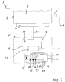
- FIG. 2 shows a schematic representation of another embodiment of a cooking appliance 1 with a display unit 18 according to the invention.
- FIG. 2 comprises a control unit 8, as already described with reference to FIG shown, a Temperaturmeßsignaleingang 7, via the one by means of a Temperaturmeßsignaltechnisch 6 received Temperaturmeßsignal received from a temperature sensor 5 becomes.
- the temperature measuring signal is applied from the temperature measuring signal input 7 Comparative means 19 forwarded, which represents the represented by the Temperaturmeßsignal Temperature with a boiling temperature of the liquid 3 compare. Exceeds the temperature the liquid 3, the boiling temperature, a boiling signal is generated.
- the control unit 8 is configured such that the power information received via a power signal input 20 is displayed with the help of the power indicator 16 only when the boiling signal is present. Further, another display 17 changes its appearance depending on one Control state of a heater 4. A user can then at the temperature display 15 of the display element 10 read that the temperature of the liquid 3 in the crucible 2 is 100 ° C. The further display 17 indicates that the heater 4 is not in a controlled state located. In addition, a user of the cooking appliance 1 on the power display 16 read that the heater 4 is not in a controlled control state, but in Figure 2, about half of the maximum possible power to the crucible 2 of the heater 4 can be delivered.
- FIG. 3 shows another embodiment of a cooking appliance 1 with an inventive Display unit 18.
- the embodiment according to FIG. 3 differs from the embodiment according to FIG. 2, in that the control unit 8 additionally comprises a control unit 21, by switching between an on state of the heater 4 and an off state of the heater 4 regulates the output to the crucible 2 power.
- the control unit 21 uses an electronic signal of a default value, via a dial 12 has been entered, as well as the temperature measuring signal of the temperature sensor 5, via the Temperaturmeßsignaltechnisch 6 to the Temperaturmeßsignaleingang. 7 has been forwarded.
- a cooking appliance 1 which is operated with water as liquid 3, can on the setting 12 either set a temperature between 0 ° C and 99 ° C or a boiling operating condition of the cooking appliance to be selected. For the temperature 100 ° C, the boiling point the liquid 3, thus several adjustment positions are available, which are those of the Heating 4 predetermined power predetermined.
- the control unit 21 Based on the input by means of the dial 12 Default value and the temperature represented by the temperature the liquid 3 in the crucible 2, the control unit 21, the control state of the heater. 4 determine or set.
- the control unit 8 further comprises a power detection unit 22, which by means of a Time integration unit 23, the output from the heater 4 to the crucible 2 power a period of the on state of the heater 4 at a further period of time turned off state of the heater 4 determined within a predetermined period of time.
- the power determination unit 22 and the control unit 21 are provided with means for receiving a power information, for example a power signal input of the control unit 8, coupled, which uses the power information to control the display element 10.
- control unit 8 and its components can be used both in hardware and in software be executed.
- control unit comprises an electrical computer unit which the functions of the various described components of the control unit takes over.
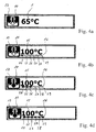
- FIG. 4a shows the state (case 1) in which the setting wheel 12 of a cooking appliance 1 according to Figure 3, a temperature of 65 ° C is preselected and the Control unit 21 by means of the heater 4, the liquid 3 is heated to a temperature of 65 ° C.
- the temperature display 15 of the display element 10 shows the measured temperature from 65 ° C.
- the further display 17 indicates that the heater 4 is in a regulated State is.
- the power indicator 16 is in this operating state of the cooking appliance 1 electrically switched to a display state not visible to a viewer.
- FIG. 4b shows the operating state (case 2), in which the temperature is adjusted by means of the setting wheel 12 of a cooking appliance 1 of Figure 3 is selected to 100 ° C and the control unit 21st the liquid 3 has been regulated in the crucible 2 by means of the heater 4 to this temperature.
- the further display 17 indicates that the control unit 21 is in a controlled state located. This is also done using a segment 24 of several segments 24-29 displayed, which is in a visible on state. The remaining segments 25-29 of the plurality of segments 24-29 are in a visible off-state.
- FIG. 4 c shows an operating state (case 3) of a cooking appliance 1 according to FIG. 3, in which FIG Help the dial 12 a temperature of 100 ° C and a state is preselected at the control unit 21 is not in a controlled state, but the crucible supplies a predetermined power greater than that for maintaining the boiling temperature required power output of 100 ° C.
- the temperature display 15 shows again 100 ° C, and the further display 17 indicates that the control unit 21 and the Heating 4 are in an unregulated condition. From the performance gauge are three Segments 24, 25, 26 in the on state, and remaining segments 27, 28, 29 of the plurality Segments 24-29 are in an off state.
- FIG. 4 d shows the operating state (case 4) of a cooking appliance 1 according to FIG. 3 the maximum temperature and power are set by means of the dial 12.
- the temperature indicator 15 of the display element 10 indicates the temperature of 100 ° C.
- the additional display 17 indicates that the control unit is in an unregulated condition located.
- the plurality of segments 24-29 are all switched to the on state, thereby it is indicated that the crucible 2, the maximum power possible using the heater. 4 is supplied.
- Figures 5a-5c characterize the various ones shown in Figures 4a, 4c and 4d Display elements correspond to operating states of the cooking appliance 1 respectively Help of a temperature-time diagram and a heating mode-time diagram.
- FIG. 5 a shows the operating state according to FIG. 4 a (case 1) of the cooking appliance 1 according to FIG. 3 shown in which by means of the dial 12, a temperature of 65 ° C is selected.
- the control unit 21 switches the heater 4 at a time 30 at which the setting takes place, in an on state (1).
- the temperature of the liquid 3 in the crucible 2 goes up. If the preselected temperature of 65 ° C is reached, the control unit 21 switches at a time 31, the heater 4 from (0). At a time 32, the temperature drops again below 65 ° C, so that the control unit 21, the heater 4 again in the on state (1) switches. In this way, the temperature of the liquid 3 in the crucible 2 kept constant at 65 ° C.
- FIG. 5b shows the operating state corresponding to the display element 18 shown in FIG. 4c (case 3).
- a temperature of 100 ° C is preselected on the dial 12 of Figure 3 and at the same time determined that about half the heating power is supplied to the crucible 2, the maximum can be supplied to the crucible 2.
- the control unit 21 switches the heater to a switched-on state (1) at a time 33. The temperature increases until it reaches 100 ° C at time 34. For a period of time the heater 4 is then switched by the control unit 21 in an off state (0). Subsequently, the heater 4 is again switched to an on state (1). The switching between the switched on and the off state then takes place continuously.
- the time spans in which the heater is in an off state (0), and the time periods Z 3 , in which the heater is in an on state (1) are about the same length. Thus, about half of the maximum possible power is delivered from the heater 4 to the crucible 2.
- FIG. 5c shows the state (case 4) of the cooking appliance 1 according to FIG. 3, in which the maximum possible power is delivered from the heater 4 to the crucible 2, in analogy to FIG. 4d.
- This operating state differs from the operating state shown in Figure 5b only in that the time period in which the heater 4 is in an off state (0), is shorter than the time period Z 4 , in which the heater 4 is in an on state (1).
- the timespan in which the heater is in an off state (0), is necessary to prevent overheating of the heater 4 and thus destruction.
- Other embodiments may be designed so that the heater 4 can remain permanently in the switched-on state (1).
Landscapes
- Engineering & Computer Science (AREA)
- Food Science & Technology (AREA)
- Cookers (AREA)
- Control Of Resistance Heating (AREA)
Abstract
Description
- Figur 1
- eine schematische Darstellung eines Gargerätes mit einem Tiegel und einer ersten Ausführungsform einer erfindungsgemäßen Anzeigeeinheit;
- Figur 2
- eine schematische Darstellung eines Gargeräts mit einem Tiegel und einer zweiten Ausführungsform einer erfindungsgemäßen Anzeigeeinheit;
- Figur 3
- eine weitere schematische Darstellung eines Gargerätes mit einem Tiegel und einer dritten Ausführungsform einer erfindungsgemäßen Anzeigeeinheit;
- Figuren 4a-4c
- Ansichten einer weiteren erfindungsgemäßen Anzeigeeinheit bei verschiedenen Betriebszuständen eines Gargerätes; und
- Figur 5a-5c
- charakterisierende Darstellungen verschiedener Betriebszustände eines Gargerätes, die jeweils mit Hilfe eines Temperatur-Zeit-Diagramms und eines Heizungsbetriebszustand-Zeit-Diagramms repräsentiert werden und mit den Anzeigedarstellungen der Figuren 4a, 4c und 4d entsprechend korrespondieren.
- 1
- Gargerät
- 2
- Tiegel
- 3
- Flüssigkeit
- 4
- Heizung
- 5
- Temperatursensor
- 6
- Temperaturmeßsignalleitung
- 7
- Temperaturmeßsignaleingang
- 8
- Steuereinheit
- 9
- Steuerleitung
- 10
- Anzeigeelement
- 11
- Bedienplatine
- 12
- Einstellrad
- 13
- Vorgabewert-Leitung
- 14
- Regelungsleitung
- 15
- Temperaturanzeige
- 16
- Leistungsanzeige
- 17
- Anzeige
- 18
- Anzeigeeinheit
- 19
- Vergleichsmittel
- 20
- Leistungssignaleingang
- 21
- Regeleinheit
- 22
- Leistungsermittlungseinheit
- 23
- Zeitintegrationseinheit
- 24-29
- Segment
- 30-34
- Zeitpunkt
Claims (19)
- Anzeigeeinheit (18) für ein Gargerät (1) mit einem mit Hilfe einer Heizung (4) beheizbaren Tiegel (2) zum Garen eines Lebensmittels, mit:gekennzeichnet durch Vergleichsmittel (19) zum Erzeugen eines Siedesignals, wenn die von dem Temperaturmeßsignal repräsentierte Temperatur größer oder gleich einer Siedetemperatur der Flüssigkeit (3) in dem Tiegel (2) ist, und eine Steuereinheit (8) zum Steuern der Leistungsanzeige (16), so daß die Leistungsanzeige (16) nur bei Vorliegen des Siedesignals die Leistungsinformation anzeigt, wobei die Steuereinheit (8) die Vergleichsmittel (19) umfaßt.einem Temperaturmeßeingang (7) Empfangen eines Temperaturmeßsignals, das die Temperatur einer Flüssigkeit (3) in dem Tiegel (2) repräsentiert;einer Temperaturanzeige (15), die die von dem Temperaturmeßsignal repräsentierte Temperatur anzeigt;Mittel (20) zum Empfangen einer Leistungsinformation, die die an den Tiegel (2) abgegebene Leistung und/oder einen Regelzustand der Heizung (4) repräsentiert; undeiner Leistungsanzeige (16) zum Anzeigen der Leistungsinformation;
- Anzeigeeinheit (18) nach Anspruch 1, dadurch gekennzeichnet, daß die Leistungsanzeige (16) mehrere Segmente (24-29) umfaßt, die jeweils getrennt zwischen mindestens zwei Anzeigezuständen elektrisch schaltbar sind.
- Anzeigeeinheit (18) nach Anspruch 2, dadurch gekennzeichnet, daß die mehreren Segmente (24-29) in einen für einen Betrachter sichtbaren Ein-Zustand und einen sichtbaren Aus-Zustand elektrisch schaltbar sind.
- Anzeigeeinheit (18) nach Anspruch 2 oder 3, dadurch gekennzeichnet, daß die Leistungsanzeige (16) gestaltet ist zum Darstellen eines geregelten Regelzustands der Heizung (4) mit Hilfe des Schaltens eines (24) der mehreren Segment (24-29) in einen Ein-Zustand und alternativ zum Darstellen der von der Heizung (4) abgegebenen Leistung mit Hilfe des Schaltens von zwei (24, 25) oder mehr der mehreren Segmente (24-29) proportional zu der von der Heizung (4) an den Tiegel (2) abgegebenen Leistung in den Ein-Zustand.
- Anzeigeeinheit (18) nach einem der vorangegangenen Ansprüche , dadurch gekennzeichnet, daß die Leistungsanzeige (16), insbesondere die mehreren Segmente, bei nicht vorliegendem Siedesignal in einen für den Betrachter im wesentlichen nicht sichtbaren Anzeigezustand elektrisch schaltbar ist.
- Anzeigeeinheit (18) nach einem der vorangegangenen Ansprüche, dadurch gekennzeichnet, daß die Temperaturanzeige (15) eine Digitalanzeige ist.
- Anzeigeeinheit (18) nach einem der vorangegangenen Ansprüche, dadurch gekennzeichnet, daß die Temperaturanzeige (15) und die Leistungsanzeige (16) in einem Anzeigeelement (10) zusammengefaßt sind.
- Anzeigeeinheit (18) nach Anspruch 7, dadurch gekennzeichnet, daß das Anzeigeelement (10) eine Flüssigkristallanzeige ist.
- Anzeigeeinheit (18) nach einem der vorangegangenen Ansprüche, gekennzeichnet durch eine weitere Anzeige (17) zum Anzeigen des Regelzustands der Heizung (4).
- Anzeigeeinheit (18) nach einem der vorangegangenen Ansprüche, gekennzeichnet durch eine von der Steuereinheit (8) umfaßte, mit den Mitteln (20) zum Empfangen der Leistungsinformation gekoppelte Regeleinheit (21) zum Regeln der von der Heizung (4) abgegebenen Leistung mit Hilfe eines Umschaltens zwischen einem eingeschalteten und einem ausgeschalteten Zustand der Heizung (4).
- Anzeigeeinheit (18) nach einem der vorangegangenen Ansprüche, gekennzeichnet durch eine von der Steuereinheit (8) umfaßte, mit den Mitteln (20) zum Empfangen der Leistungsinformation gekoppelte Leistungsermittlungseinheit (22) zum Ermitteln der an den Tiegel (2) abgegebenen Leistung mit Hilfe einer Zeitintegrationseinheit (23) anhand eines Verhältnisses einer Zeitdauer des eingeschalteten Zustands der Heizung (4) zu einer weiteren Zeitdauer des ausgeschalteten Zustands der Heizung (4) innerhalb einer vorgegebenen Zeitspanne.
- Anzeigeeinheit (18) nach einem der Ansprüche 10 oder 11, gekennzeichnet durch Eingabemittel (12) zum Erfassen eines Vorgabewertes, wobei die Regeleinheit (21) zum Bestimmen des Regelzustands der Heizung (4) anhand des Vorgabewerts und der von dem Temperaturmeßsignal repräsentierten Temperatur gestaltet ist.
- Verfahren zum Anzeigen einer Temperatur und einer Leistungsinformation für ein Gargerät (1) mit einem mit Hilfe einer Heizung (4) beheizbaren Tiegel (2) zum Garen eines Lebensmittels mit folgenden Schritten:gekennzeichnet durch folgende Schritte:Empfangen eines Temperaturmeßsignals, das die Temperatur einer Flüssigkeit (3) in dem Tiegel (2) repräsentiert;Anzeigen der von dem Temperaturmeßsignal repräsentierten Temperatur mit Hilfe einer Temperaturanzeige (15); undEmpfangen einer Leistungsinformation, die die an den Tiegel (2) abgegebene Leistung und/oder einen Regelzustand der Heizung (4) repräsentiert;Vergleichen der von dem Temperatursignal repräsentierten Temperatur mit einer Siedetemperatur der Flüssigkeit (3) mit Hilfe von Vergleichsmitteln (19) und Erzeugen eines Siedesignals, wenn die von dem Temperaturmeßsignal repräsentierte Temperatur größer oder gleich der Siedetemperatur der Flüssigkeit (3) in dem Tiegel (2) ist, undSteuern der Leistungsanzeige (16) mit Hilfe einer Steuereinheit (8), so daß die Leistungsanzeige (16) nur bei Vorliegen des Siedesignals die Leistungsinformation anzeigt.
- Verfahren nach Anspruch 13, dadurch gekennzeichnet, daß das die Leistungsanzeige (16) in einen für einen Betrachter im wesentlichen nicht sichtbaren Zustand elektrisch geschaltet wird, wenn das Siedesignal nicht vorliegt.
- Verfahren nach Anspruch 13 oder 14, dadurch gekennzeichnet, daß ein Segment (24) von mehreren Segmenten (24-29) der Leistungsanzeige (16) in einen Ein-Zustand und die übrigen der mehreren Segmente (24-29) in einen Aus-Zustand geschaltet werden, wenn das Siedesignals vorliegt und der die Leistungsinformation den geregelten Regelzustand der Heizung (4) repräsentiert.
- Verfahren nach einem der Ansprüche 13 bis 15, dadurch gekennzeichnet, daß zwei (24, 25) oder mehr der mehreren Segmente (24-29) proportional zu der von der Heizung (4) an den Tiegel (2) abgegebenen Leistung in den Ein-Zustand geschaltet werden, wenn das Siedesignal vorliegt und die Leistungsinformation die an den Tiegel (2) abgegebene Leistung der Heizung (4) repräsentiert.
- Verfahren nach einem der Ansprüche 13 bis 16, dadurch gekennzeichnet, daß die Heizung (4) mit Hilfe einer Regeleinheit (21) geregelt wird, indem die Heizung (4) zwischen einem eingeschalteten und einem ausgeschalteten Zustand umgeschaltet wird.
- Verfahren nach einem der Ansprüche 13 bis 17, gekennzeichnet durch ein Ermitteln der von der Heizung (4) abgegebenen Leistung mit Hilfe einer Zeitintegration zum Bestimmen eines Verhältnisses einer Zeitdauer des eingeschalteten Zustands der Heizung (4) zu einer weiteren Zeitdauer des ausgeschalteten Zustands der Heizung (4) innerhalb einer vorgegebenen Zeitspanne.
- Verfahren nach einem der Ansprüche 17 oder 18, dadurch gekennzeichnet, daß mit Hilfe von Eingabemitteln ein Vorgabewert in ein elektronisches Signal gewandelt wird, anhand dessen die Regeleinheit (21) in Abhängigkeit von der von dem Temperaturmeßsignal repräsentierten Temperatur den Regelzustand der Heizung (4) bestimmt.
Priority Applications (2)
| Application Number | Priority Date | Filing Date | Title |
|---|---|---|---|
| EP20030291808 EP1500362B1 (de) | 2003-07-22 | 2003-07-22 | Anzeigeeinheit für ein Gargerät und Verfahren zum Anzeigen einer Temperatur und einer Leistungsinformation |
| DE50300664T DE50300664D1 (de) | 2003-07-22 | 2003-07-22 | Anzeigeeinheit für ein Gargerät und Verfahren zum Anzeigen einer Temperatur und einer Leistungsinformation |
Applications Claiming Priority (1)
| Application Number | Priority Date | Filing Date | Title |
|---|---|---|---|
| EP20030291808 EP1500362B1 (de) | 2003-07-22 | 2003-07-22 | Anzeigeeinheit für ein Gargerät und Verfahren zum Anzeigen einer Temperatur und einer Leistungsinformation |
Publications (2)
| Publication Number | Publication Date |
|---|---|
| EP1500362A1 true EP1500362A1 (de) | 2005-01-26 |
| EP1500362B1 EP1500362B1 (de) | 2005-06-15 |
Family
ID=33484047
Family Applications (1)
| Application Number | Title | Priority Date | Filing Date |
|---|---|---|---|
| EP20030291808 Expired - Lifetime EP1500362B1 (de) | 2003-07-22 | 2003-07-22 | Anzeigeeinheit für ein Gargerät und Verfahren zum Anzeigen einer Temperatur und einer Leistungsinformation |
Country Status (2)
| Country | Link |
|---|---|
| EP (1) | EP1500362B1 (de) |
| DE (1) | DE50300664D1 (de) |
Citations (5)
| Publication number | Priority date | Publication date | Assignee | Title |
|---|---|---|---|---|
| JPH04336010A (ja) * | 1991-05-10 | 1992-11-24 | Mitsubishi Electric Home Appliance Co Ltd | 炊飯器 |
| GB2276243A (en) * | 1993-02-23 | 1994-09-21 | Nova Electro Int | Cooking appliance |
| US5827556A (en) * | 1996-10-23 | 1998-10-27 | Tridelta Industries, Inc. | Electronic controller for heating apparatus |
| DE20020878U1 (de) * | 2000-12-11 | 2001-06-07 | Hetterich, Winfried, Dr., 97440 Werneck | Haushaltskochtopf |
| US20030094448A1 (en) * | 2001-10-09 | 2003-05-22 | Sanjay Shukla | Electronic power control for cooktop heaters |
-
2003
- 2003-07-22 EP EP20030291808 patent/EP1500362B1/de not_active Expired - Lifetime
- 2003-07-22 DE DE50300664T patent/DE50300664D1/de not_active Expired - Lifetime
Patent Citations (5)
| Publication number | Priority date | Publication date | Assignee | Title |
|---|---|---|---|---|
| JPH04336010A (ja) * | 1991-05-10 | 1992-11-24 | Mitsubishi Electric Home Appliance Co Ltd | 炊飯器 |
| GB2276243A (en) * | 1993-02-23 | 1994-09-21 | Nova Electro Int | Cooking appliance |
| US5827556A (en) * | 1996-10-23 | 1998-10-27 | Tridelta Industries, Inc. | Electronic controller for heating apparatus |
| DE20020878U1 (de) * | 2000-12-11 | 2001-06-07 | Hetterich, Winfried, Dr., 97440 Werneck | Haushaltskochtopf |
| US20030094448A1 (en) * | 2001-10-09 | 2003-05-22 | Sanjay Shukla | Electronic power control for cooktop heaters |
Non-Patent Citations (1)
| Title |
|---|
| PATENT ABSTRACTS OF JAPAN vol. 017, no. 180 (C - 1046) 8 April 1993 (1993-04-08) * |
Also Published As
| Publication number | Publication date |
|---|---|
| DE50300664D1 (de) | 2005-07-21 |
| EP1500362B1 (de) | 2005-06-15 |
Similar Documents
| Publication | Publication Date | Title |
|---|---|---|
| EP2069690B1 (de) | Gargerät mit automatischer garprogrammvorauswahl und verfahren zum einstellen solch eines gargeräts | |
| DE102014105161B4 (de) | Verfahren zum Betreiben einer Kochfeldeinrichtung und Kochfeldeinrichtung | |
| DE69100390T2 (de) | Mit einem Mikrocomputer betriebener Mikrowellenofen gemäss Kochprogrammen, die in einem Datenspeicher gespeichert sind. | |
| EP2215408B1 (de) | Kochfeld mit einer hausgerätanzeigevorrichtung | |
| DE2950517C1 (de) | Heizvorrichtung | |
| EP1272007A2 (de) | Kochfeld-Steuerung | |
| AT409172B (de) | Vorrichtung zum bedienen eines elektrischen küchenherdes | |
| WO2009053279A1 (de) | Kochfeld und verfahren zum betreiben eines kochfelds | |
| EP3163174A2 (de) | Gargeräteanordnung zur zubereitung von mindestens zwei gargütern | |
| EP2370734A2 (de) | Kochfeld mit einem bildschirm und verfahren zum betreiben eines kochfelds | |
| DE10361341A1 (de) | Vorrichtung zur Bedienung eines Kochfeldes | |
| EP1158838B1 (de) | Berührungsschalteinrichtung | |
| EP2066148A1 (de) | Kochfeld mit einem Temperatursensor und einer Benutzerschnittstelle mit einem graphischen Display und Verfahren zum Betreiben eines Kochfelds | |
| DE102008027597A1 (de) | Anzeigeeinrichtung und Gargerät sowie Küchennetzwerk mit zumindest einer solchen Anzeigeeinrichtung | |
| DE102011102394B4 (de) | Vorrichtung und Verfahren zur Bedienung eines Kochfeldes | |
| EP2250538A1 (de) | Verfahren zur visuellen anzeige der qualität von auf einer energieübertragungsanlage übertragener energie | |
| DE19958662B4 (de) | Intensitätssteuerung mit einem einzigen Knopf zur Verwendung in einer digitalen Test- und Meßapparatur | |
| DE3407942A1 (de) | Digitales messgeraet zur quasi analogen messwertanzeige | |
| EP1500362B1 (de) | Anzeigeeinheit für ein Gargerät und Verfahren zum Anzeigen einer Temperatur und einer Leistungsinformation | |
| DE10342321A1 (de) | Steuerung für ein Haushaltgerät und Anzeige von Informationen | |
| DE60114913T2 (de) | Vorrichtung zum Eingeben von Schweissbedingungen | |
| EP3702747A1 (de) | Kochfeldvorrichtung | |
| EP2281419B1 (de) | Anzeigeeinrichtung und gargerät damit | |
| DE102011006274B3 (de) | Steuergerät für ein Kochfeld mit mehreren Kochstellen und zugehöriges Betriebsverfahren | |
| EP1486733B1 (de) | Backofengerät |
Legal Events
| Date | Code | Title | Description |
|---|---|---|---|
| GRAP | Despatch of communication of intention to grant a patent |
Free format text: ORIGINAL CODE: EPIDOSNIGR1 |
|
| GRAS | Grant fee paid |
Free format text: ORIGINAL CODE: EPIDOSNIGR3 |
|
| PUAI | Public reference made under article 153(3) epc to a published international application that has entered the european phase |
Free format text: ORIGINAL CODE: 0009012 |
|
| 17P | Request for examination filed |
Effective date: 20040109 |
|
| AK | Designated contracting states |
Kind code of ref document: A1 Designated state(s): AT BE BG CH CY CZ DE DK EE ES FI FR GB GR HU IE IT LI LU MC NL PT RO SE SI SK TR |
|
| AX | Request for extension of the european patent |
Extension state: AL LT LV MK |
|
| GRAA | (expected) grant |
Free format text: ORIGINAL CODE: 0009210 |
|
| AK | Designated contracting states |
Kind code of ref document: B1 Designated state(s): DE FR GB IT |
|
| REG | Reference to a national code |
Ref country code: GB Ref legal event code: FG4D Free format text: NOT ENGLISH |
|
| GBT | Gb: translation of ep patent filed (gb section 77(6)(a)/1977) |
Effective date: 20050615 |
|
| REF | Corresponds to: |
Ref document number: 50300664 Country of ref document: DE Date of ref document: 20050721 Kind code of ref document: P |
|
| AKX | Designation fees paid |
Designated state(s): DE FR GB IT |
|
| ET | Fr: translation filed | ||
| PLBE | No opposition filed within time limit |
Free format text: ORIGINAL CODE: 0009261 |
|
| STAA | Information on the status of an ep patent application or granted ep patent |
Free format text: STATUS: NO OPPOSITION FILED WITHIN TIME LIMIT |
|
| 26N | No opposition filed |
Effective date: 20060316 |
|
| PGFP | Annual fee paid to national office [announced via postgrant information from national office to epo] |
Ref country code: GB Payment date: 20130723 Year of fee payment: 11 |
|
| GBPC | Gb: european patent ceased through non-payment of renewal fee |
Effective date: 20140722 |
|
| PG25 | Lapsed in a contracting state [announced via postgrant information from national office to epo] |
Ref country code: GB Free format text: LAPSE BECAUSE OF NON-PAYMENT OF DUE FEES Effective date: 20140722 |
|
| REG | Reference to a national code |
Ref country code: FR Ref legal event code: PLFP Year of fee payment: 14 |
|
| REG | Reference to a national code |
Ref country code: FR Ref legal event code: PLFP Year of fee payment: 15 |
|
| REG | Reference to a national code |
Ref country code: FR Ref legal event code: PLFP Year of fee payment: 16 |
|
| REG | Reference to a national code |
Ref country code: DE Ref legal event code: R084 Ref document number: 50300664 Country of ref document: DE |
|
| PGFP | Annual fee paid to national office [announced via postgrant information from national office to epo] |
Ref country code: FR Payment date: 20210721 Year of fee payment: 19 Ref country code: IT Payment date: 20210730 Year of fee payment: 19 |
|
| PGFP | Annual fee paid to national office [announced via postgrant information from national office to epo] |
Ref country code: DE Payment date: 20210721 Year of fee payment: 19 |
|
| REG | Reference to a national code |
Ref country code: DE Ref legal event code: R119 Ref document number: 50300664 Country of ref document: DE |
|
| PG25 | Lapsed in a contracting state [announced via postgrant information from national office to epo] |
Ref country code: FR Free format text: LAPSE BECAUSE OF NON-PAYMENT OF DUE FEES Effective date: 20220731 |
|
| PG25 | Lapsed in a contracting state [announced via postgrant information from national office to epo] |
Ref country code: DE Free format text: LAPSE BECAUSE OF NON-PAYMENT OF DUE FEES Effective date: 20230201 |
|
| PG25 | Lapsed in a contracting state [announced via postgrant information from national office to epo] |
Ref country code: IT Free format text: LAPSE BECAUSE OF NON-PAYMENT OF DUE FEES Effective date: 20220722 |