EP1500325A2 - Bindearm einer Bindevorrichtung - Google Patents
Bindearm einer Bindevorrichtung Download PDFInfo
- Publication number
- EP1500325A2 EP1500325A2 EP04103323A EP04103323A EP1500325A2 EP 1500325 A2 EP1500325 A2 EP 1500325A2 EP 04103323 A EP04103323 A EP 04103323A EP 04103323 A EP04103323 A EP 04103323A EP 1500325 A2 EP1500325 A2 EP 1500325A2
- Authority
- EP
- European Patent Office
- Prior art keywords
- twine
- binding arm
- guide part
- binding
- arm according
- Prior art date
- Legal status (The legal status is an assumption and is not a legal conclusion. Google has not performed a legal analysis and makes no representation as to the accuracy of the status listed.)
- Withdrawn
Links
- 239000011230 binding agent Substances 0.000 abstract 1
- 238000003825 pressing Methods 0.000 description 12
- 229910000831 Steel Inorganic materials 0.000 description 6
- 239000010959 steel Substances 0.000 description 6
- 238000005520 cutting process Methods 0.000 description 4
- 238000000034 method Methods 0.000 description 4
- 239000004033 plastic Substances 0.000 description 4
- 238000004519 manufacturing process Methods 0.000 description 2
- 239000000463 material Substances 0.000 description 2
- 239000002184 metal Substances 0.000 description 2
- 230000002093 peripheral effect Effects 0.000 description 2
- 238000000926 separation method Methods 0.000 description 2
- XLYOFNOQVPJJNP-UHFFFAOYSA-N water Substances O XLYOFNOQVPJJNP-UHFFFAOYSA-N 0.000 description 2
- 244000198134 Agave sisalana Species 0.000 description 1
- 235000015842 Hesperis Nutrition 0.000 description 1
- 235000012633 Iberis amara Nutrition 0.000 description 1
- 239000000853 adhesive Substances 0.000 description 1
- 230000001070 adhesive effect Effects 0.000 description 1
- 230000006835 compression Effects 0.000 description 1
- 238000007906 compression Methods 0.000 description 1
- 239000000428 dust Substances 0.000 description 1
- 239000002985 plastic film Substances 0.000 description 1
- 230000000284 resting effect Effects 0.000 description 1
Images


Classifications
-
- A—HUMAN NECESSITIES
- A01—AGRICULTURE; FORESTRY; ANIMAL HUSBANDRY; HUNTING; TRAPPING; FISHING
- A01F—PROCESSING OF HARVESTED PRODUCE; HAY OR STRAW PRESSES; DEVICES FOR STORING AGRICULTURAL OR HORTICULTURAL PRODUCE
- A01F15/00—Baling presses for straw, hay or the like
- A01F15/08—Details
- A01F15/14—Tying devices specially adapted for baling presses
- A01F15/141—Tying devices specially adapted for baling presses for round balers
Definitions
- the invention relates to a binding arm of a binding device in a round baler.
- EP-A1-1 308 080 discloses a round baler with a Tying device, the twine from the top through a gap get into a press chamber. The twine is using a binding arm led to the gap as soon as the binding process should begin, whereupon a free hanging end section of the twine from that moving in the baling chamber Round bales is taken. Once the round bale is sufficient wrapped with twine, the twine is short-lived clamped to make it into the surface of the round bale moves in, and then separated. Because the twine is under high tension immediately before disconnecting, it purrs after separating and goes up spun.
- Binding device can be used with sisal or plastic yarn both in a fixed-chamber press as well as in a press room variable size work.
- the Binding device can be used with sisal or plastic yarn both in a fixed-chamber press as well as in a press room variable size work.
- the Binding device In the simplest form is the as Pipe or channel formed Bindearm bent down.
- the guide member may be formed in yielding, z. B. as elastic metal part, as plastic part, rubber part and like. This flexibility slows down the movement the twine and on the other hand, it allows the binding arm Obstacles, z. B. shooters, etc. to move past.
- a coil spring - tension spring or compression spring - is a commercial, cost-effective part, which is both a good Yielding as well as good leadership.
- a steel spring can with thin spring wire and be formed of a high pitch, so that no dust or crumbling pressed material attaches and the twine run with special needs.
- a hose, z. B. a water hose of one inch Diameter, also provides a cost effective alternative, especially such a hose on a known binding arm can be placed and secured by a clamp.
- a chain is another alternative, especially as it is due her weight always hanging down, in her limbs Can lead twine and is sufficiently flexible. It can Both a normal link chain can be used in all Can deflect directions, as well as a Gaelic or Socket chain (bicycle chain or the like.) Only in one direction buckles; with the last kind of chain can also be the Control movement of the twine.
- Rope z. B. a stiff steel cable, with a loop, eyelet or the like, in which the twine is captively guided.
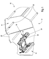
- FIG. 1 shows a round baler 10 with a frame 12, a pressing chamber 14 and a binding device 16.
- Round baler 10 is used in agriculture or in the Commercial uses and serves for the production of cylindrical Bales, wrapped at the press process end with twine 18 and thus held together. Round balers 10 are in themselves well known, z. B. of the series JOHN DEERE 575, so that details do not need to be described.
- the frame 12 is composed of a chassis, a drawbar and The like, but is only in the drawing of side walls 20 representing the pressing chamber finish at the front.
- the walls 20 are about struts 22 with connected to corresponding walls on the other side, so that the pressing chamber 14 is made stable. Between the walls 20, the binding device 16 is held, in one front, upper area.
- the pressing chamber 14 is frontally of the walls 20 and circumferentially closed by rollers 24, of which only one only one is shown. Nearly twenty such rollers 24 extend are in the direction of the struts 22 and are on a circular path arranged, which has a first lower gap or gap to the inlet of the pressed material and a second upper gap or gap to the inlet of twine 18 each in the pressing chamber 14 leaves.
- the pressing chamber 14 is in her Size constant, but this is not mandatory.
- the pressing chamber 14 could also be of variable size and / or surrounded by straps and / or bar chains.
- the Press chamber 14 is a not shown round bales always in Rotation held so that introduced at the end of the pressing process Twine 18 between the rollers 24 and the round bale recorded and taken away.
- the binding device 16 is used to supply the twine 18 in the pressing chamber 14, whose lateral guidance on the Peripheral surface of the rotating round bale and its separation, as soon as enough twine 18 is wrapped around the round bale - all This is well known and therefore only so far described as this for the understanding of the present Invention is required.
- the binding device 16 contains in the present embodiment, two binding arms 26, the above the illustrated roller 24 twine 18 in the Insert pressing chamber 14. Instead, a single could Bindearm 26 are provided. Each binding arm 26 takes three striking positions - a resting position, a Bindestart ein and a cutting position - in which he respectively is guided by a motor.
- the binding arm 26 In the rest position, the binding arm 26 extends approximately parallel to the longitudinal direction of the rollers 24.
- the twine 18 is in the upper gap between the rollers 24th guided so that it falls down into the pressing chamber 14 and there captured by the rotating round bales and taken becomes. It is important that the twine 18 hang down so far, that it can be detected. It must therefore be avoided that the free hanging end of the twine 18 is curved or hangs on the binding arm 26.
- the binding arms 26 Located in the cutting position the binding arms 26 are approximately perpendicular to the longitudinal axis of the Rolls 24 and in operative connection with a cutting device 28.
- the binding arm 26 is provided with a guide member 30, which is the Twine 18 leads on a part of its length and thus prevents it from performing an uncontrolled movement can cause the end section to cease to gap extends into the pressing chamber 14. Even if this danger at a extending horizontally or substantially horizontally Bindearm 26 is the largest, so even at one more upright arranged binding arm of the guide member 30 may be helpful.
- each of the otherwise free Section of the binding arm 26 with the guide member 30 and a End portion of the twine 18 show.
- the guide member 30 as a link chain formed with a clamp 32 to the underside of the tubular binding arms 26 is attached.
- the guide part 30 has in this case five links 34, of which the first, upper clamped between the clamp 32 and the binding arm 26 and the hang down remaining four members 34.
- the twine 18 is passed through the lower members 34, so that when The twine 18 recovers after the cutting process is caught and can not wrap around the binding arm 26, because this would require the guide part 30, d. H. the heavy chain take.
- the guide part 30 is formed as a bow, which extends down and at the bottom with a flexible sleeve 36 is provided.
- the bow can be made of metal or plastic and screwed on, plugged or be glued on.
- a hose 38 is attached.
- the hose 38 can with a clamp, not shown or Clamp, secured by adhesive or otherwise become.
- the hose 38 should be equipped with steel inserts or otherwise sufficiently rigid. in principle could be a water hose of one inch diameter be.
- FIG. 5 shows a variant in which a plastic is used sheathed steel rope at the upper end by means of a Rope clamp 40 attached to the free end of the binding arm 26 and at the lower end is provided with a loop 42 through the twine 18 extends.
- FIG. 6 an embodiment is shown in Figure 6, at a helical spring is used as a guide member 30.
- This guide member 30 is by means of a carriage bolt 44 at the binding arm 26 connected.
Landscapes
- Life Sciences & Earth Sciences (AREA)
- Environmental Sciences (AREA)
- Basic Packing Technique (AREA)
- Package Frames And Binding Bands (AREA)
Abstract
Description
- Fig. 1
- einen Teil einer Rundballenpresse mit einer Bindevorrichtung,
- Fig. 2
- einen Bindearm der Bindevorrichtung mit einer Kette als Führungsteil,
- Fig. 3
- einen Bindearm der Bindevorrichtung mit einem Fitting und einer nachgiebigen Manschette als Führungsteil,
- Fig. 4
- einen Bindearm der Bindevorrichtung mit einem Schlauch als Führungsteil und
- Fig. 5
- einen Bindearm der Bindevorrichtung mit einem Stahlseil als Führungsteil und
- Fig. 6
- einen Bindearm der Bindevorrichtung mit einer Feder als Führungsteil.
Claims (8)
- Bindearm (26) einer Bindevorrichtung (16), die Bindegarn (18) abweichend von der Verlaufsrichtung in ihm nach unten abgibt, dadurch gekennzeichnet, dass er in einem aufrechten Führungsteil (30) endet.
- Bindearm nach Anspruch 1, dadurch gekennzeichnet, dass der Führungsteil (30) als ein Rohr oder Fitting ausgebildet ist.
- Bindearm nach Anspruch 2, dadurch gekennzeichnet, dass der Führungsteil (30) ausgangsseitig nachgiebig, insbesondere elastisch, ausgebildet oder mit einem derartigen Endabschnitt versehen ist.
- Bindearm nach Anspruch 1, dadurch gekennzeichnet, dass der Führungsteil (30) nachgiebig ausgebildet ist.
- Bindearm nach Anspruch 4, dadurch gekennzeichnet, dass der Führungsteil (30) als eine Schraubenfeder oder ein Schlauch (38) ausgebildet ist, durch deren/dessen Innenraum das Bindegarn (18) geführt ist.
- Bindearm nach Anspruch 4, dadurch gekennzeichnet, dass der Führungsteil (30) als eine Kette ausgebildet ist, durch deren Glieder (34) das Bindegarn (18) geführt ist.
- Bindearm nach Anspruch 4, dadurch gekennzeichnet, dass der Führungsteil (30) als ein Seil mit wenigstens einer Schlaufe (42) ausgebildet ist, durch deren Innenraum das Bindegarn (18) geführt ist.
- Bindearm nach einem oder mehreren der vorherigen Ansprüche, dadurch gekennzeichnet, dass der Führungsteil (30) mittels einer Klemme, Schelle (32) oder dergleichen anbringbar ist.
Applications Claiming Priority (2)
| Application Number | Priority Date | Filing Date | Title |
|---|---|---|---|
| DE10333592A DE10333592B4 (de) | 2003-07-24 | 2003-07-24 | Bindearm einer Bindevorrichtung |
| DE10333592 | 2003-07-24 |
Publications (2)
| Publication Number | Publication Date |
|---|---|
| EP1500325A2 true EP1500325A2 (de) | 2005-01-26 |
| EP1500325A3 EP1500325A3 (de) | 2006-03-15 |
Family
ID=33483035
Family Applications (1)
| Application Number | Title | Priority Date | Filing Date |
|---|---|---|---|
| EP04103323A Withdrawn EP1500325A3 (de) | 2003-07-24 | 2004-07-13 | Bindearm einer Bindevorrichtung |
Country Status (3)
| Country | Link |
|---|---|
| US (1) | US7263927B2 (de) |
| EP (1) | EP1500325A3 (de) |
| DE (1) | DE10333592B4 (de) |
Cited By (1)
| Publication number | Priority date | Publication date | Assignee | Title |
|---|---|---|---|---|
| CN108190153A (zh) * | 2017-12-28 | 2018-06-22 | 梁启明 | 一种导管的卷绕机构 |
Citations (1)
| Publication number | Priority date | Publication date | Assignee | Title |
|---|---|---|---|---|
| EP1308080A2 (de) | 2001-10-30 | 2003-05-07 | Deere & Company | Bindevorrichtung für eine Rundballenpresse |
Family Cites Families (7)
| Publication number | Priority date | Publication date | Assignee | Title |
|---|---|---|---|---|
| US3910178A (en) * | 1973-10-12 | 1975-10-07 | Sperry Rand Corp | Apparatus for wrapping a round bale formed in a round bale forming machine |
| JPS5934328B2 (ja) * | 1975-08-22 | 1984-08-22 | 株式会社クボタ | 結束装置における紐通し案内具 |
| FR2506117B1 (fr) * | 1981-05-22 | 1985-06-14 | Meslong Robert | Machine pour collecter les sarments de vigne |
| US4457226A (en) * | 1981-09-17 | 1984-07-03 | Deere & Company | Twine-wrapping mechanism for a large round baler |
| EP0090120B1 (de) * | 1982-03-31 | 1985-09-18 | JOHN DEERE (Société Anonyme) | Bindevorrichtung mittels zwei Bindfäden für Rundballenpresse |
| DE3414080A1 (de) * | 1984-04-13 | 1985-10-24 | Klöckner-Humboldt-Deutz AG Zweigniederlassung Fahr, 7702 Gottmadingen | Vorrichtung zum binden von rollballen aus landwirtschaftlichem erntegut |
| US5215005A (en) * | 1992-03-09 | 1993-06-01 | Ford New Holland, Inc. | Telescopic twine arm for round baler twine wrapping apparatus |
-
2003
- 2003-07-24 DE DE10333592A patent/DE10333592B4/de not_active Expired - Fee Related
-
2004
- 2004-07-02 US US10/884,774 patent/US7263927B2/en not_active Expired - Fee Related
- 2004-07-13 EP EP04103323A patent/EP1500325A3/de not_active Withdrawn
Patent Citations (1)
| Publication number | Priority date | Publication date | Assignee | Title |
|---|---|---|---|---|
| EP1308080A2 (de) | 2001-10-30 | 2003-05-07 | Deere & Company | Bindevorrichtung für eine Rundballenpresse |
Cited By (2)
| Publication number | Priority date | Publication date | Assignee | Title |
|---|---|---|---|---|
| CN108190153A (zh) * | 2017-12-28 | 2018-06-22 | 梁启明 | 一种导管的卷绕机构 |
| CN108190153B (zh) * | 2017-12-28 | 2023-08-08 | 梁启明 | 一种导管的卷绕机构 |
Also Published As
| Publication number | Publication date |
|---|---|
| US20050028687A1 (en) | 2005-02-10 |
| DE10333592A1 (de) | 2005-03-10 |
| DE10333592B4 (de) | 2012-08-02 |
| US7263927B2 (en) | 2007-09-04 |
| EP1500325A3 (de) | 2006-03-15 |
Similar Documents
| Publication | Publication Date | Title |
|---|---|---|
| DE69707050T2 (de) | Ernteaufsammeleinrichtung | |
| DE2443838C3 (de) | Aufsammel-Rollballenpresse | |
| DE7835014U1 (de) | Maschine zum aufwickeln von faserigem erntegut zu grossen rundballen | |
| DE202017007380U1 (de) | Schneidmesser-Überlastsicherung | |
| EP0447822A2 (de) | Liegebox-Aufstallung | |
| WO1997014203A1 (de) | Einrichtung zum einziehen eines elektrokabels für hausinstallationen | |
| DE68911838T2 (de) | Riemenspannungsvorrichtung für eine Rundballenpresse. | |
| DE2530320C3 (de) | Bindevorrichtung für Wickelballenpressen | |
| DE2947446A1 (de) | Maschine zum formen von rundballen aus erntegut | |
| EP2055661A2 (de) | Befestigung für eine Leine an einer Rolle | |
| EP0095689B1 (de) | Rundballenpresse mit einem einen Guteinlass aufweisenden Ballenpressraum | |
| DE2921821A1 (de) | Vorrichtung zur seitlichen begrenzung eines viehstandes | |
| DE10153517B4 (de) | Bindevorrichtung für eine Rundballenpresse | |
| DE2330365A1 (de) | Einrichtung zum abnehmen eines stuecks von einem ausgeschnittenen stapel | |
| EP1500325A2 (de) | Bindearm einer Bindevorrichtung | |
| DE7205300U (de) | Harnischglied mit weblitze bzw. federanker und elastischer zugkordel bei einer jacquardmaschine | |
| DE102006059265A1 (de) | Landwirtschaftliche Presse | |
| DE69903286T2 (de) | Werkzeug zum spannen von drähten | |
| EP1438890A1 (de) | Garnspanneinrichtung und Grossballenpresse | |
| DE10335883A1 (de) | Rundballenpresse | |
| DE3044445A1 (de) | Nachmelk- und melkzeugabnahmevorrichtung | |
| DE102007019187B3 (de) | Rebenbearbeitungseinrichtung | |
| EP0981947B1 (de) | Garnführungszusammenbau und Rundballenpresse | |
| DE1786101A1 (de) | Spannvorrichtung | |
| DE3408149A1 (de) | Bindegarn-spannvorrichtung |
Legal Events
| Date | Code | Title | Description |
|---|---|---|---|
| PUAI | Public reference made under article 153(3) epc to a published international application that has entered the european phase |
Free format text: ORIGINAL CODE: 0009012 |
|
| AK | Designated contracting states |
Kind code of ref document: A2 Designated state(s): AT BE BG CH CY CZ DE DK EE ES FI FR GB GR HU IE IT LI LU MC NL PL PT RO SE SI SK TR |
|
| AX | Request for extension of the european patent |
Extension state: AL HR LT LV MK |
|
| PUAL | Search report despatched |
Free format text: ORIGINAL CODE: 0009013 |
|
| AK | Designated contracting states |
Kind code of ref document: A3 Designated state(s): AT BE BG CH CY CZ DE DK EE ES FI FR GB GR HU IE IT LI LU MC NL PL PT RO SE SI SK TR |
|
| AX | Request for extension of the european patent |
Extension state: AL HR LT LV MK |
|
| 17P | Request for examination filed |
Effective date: 20060915 |
|
| AKX | Designation fees paid |
Designated state(s): AT BE BG CH CY CZ DE DK EE ES FI FR GB GR HU IE IT LI LU MC NL PL PT RO SE SI SK TR |
|
| 17Q | First examination report despatched |
Effective date: 20070221 |
|
| STAA | Information on the status of an ep patent application or granted ep patent |
Free format text: STATUS: THE APPLICATION IS DEEMED TO BE WITHDRAWN |
|
| 18D | Application deemed to be withdrawn |
Effective date: 20070704 |