EP1500318B1 - Autonomous device for the magnetic handling of an electronic component - Google Patents
Autonomous device for the magnetic handling of an electronic component Download PDFInfo
- Publication number
- EP1500318B1 EP1500318B1 EP03740653A EP03740653A EP1500318B1 EP 1500318 B1 EP1500318 B1 EP 1500318B1 EP 03740653 A EP03740653 A EP 03740653A EP 03740653 A EP03740653 A EP 03740653A EP 1500318 B1 EP1500318 B1 EP 1500318B1
- Authority
- EP
- European Patent Office
- Prior art keywords
- magnet
- component
- handling device
- head
- gripping
- Prior art date
- Legal status (The legal status is an assumption and is not a legal conclusion. Google has not performed a legal analysis and makes no representation as to the accuracy of the status listed.)
- Expired - Lifetime
Links
Images

Classifications
-
- H—ELECTRICITY
- H05—ELECTRIC TECHNIQUES NOT OTHERWISE PROVIDED FOR
- H05K—PRINTED CIRCUITS; CASINGS OR CONSTRUCTIONAL DETAILS OF ELECTRIC APPARATUS; MANUFACTURE OF ASSEMBLAGES OF ELECTRICAL COMPONENTS
- H05K13/00—Apparatus or processes specially adapted for manufacturing or adjusting assemblages of electric components
- H05K13/04—Mounting of components, e.g. of leadless components
- H05K13/0447—Hand tools therefor
Definitions
- the invention aims to provide an electronic component handling device that is autonomous and that does not involve any direct manual intervention on the component.
- the device is characterized in that said gripping head is pivotally mounted on said body.
- the dimensions as well as the material of the magnet 4 are provided so that it can support 3 to 5 times the weight of the component.
Abstract
Description
Le domaine de l'invention est celui de la manipulation de composants électroniques, en vue notamment de leur montage ou de leur remplacement sur un circuit imprimé. Plus précisément, l'invention concerne les outils munis d'une tête de préhension permettant de saisir et déplacer un tel composant.The field of the invention is that of the manipulation of electronic components, in particular for their mounting or replacement on a printed circuit. More specifically, the invention relates to tools provided with a gripping head for gripping and moving such a component.
L'invention trouve des applications dans de très nombreux domaines, tels que les télécommunications, les échanges de données sans fil ("wireless" en anglais), l'automobile, l'électronique, l'électronique embarquée, l'industrie de l'électronique et du report de composants, l'industrie chimique, les laboratoires, le médical.The invention has applications in a very large number of fields, such as telecommunications, wireless data exchanges ("wireless"), automotive, electronics, embedded electronics, the electronics industry, electronics and report of components, the chemical industry, laboratories, the medical.
Par composant électronique, on entend ici tout type de composant susceptible d'être manipulé, et qu'il faut manipuler avec soin et précision, sans détérioration notamment lors de sa mise en place. Il s'agit donc en particulier des composants présentant à leur surface et/ou à leur périphérie des broches destinées à être brasées sur un circuit imprimé.By electronic component, here means any type of component that can be manipulated, and that must be handled with care and precision, without deterioration especially during its implementation. It is therefore in particular components having on their surface and / or at their periphery pins for brazing on a printed circuit.
Il peut par exemple s'agir de composants classiques (microprocesseurs, mémoires,...), de composants hybrides, de composants CMS, de macro-composants.It may for example be conventional components (microprocessors, memories, ...), hybrid components, CMS components, macro-components.
Par niacro-composant, on entend ici les dispositifs regroupant, dans un même boîtier (formant généralement blindage) destiné à être monté sur un circuit imprimé, plusieurs composants. De tels macro-composants sont notamment décrits dans le FR-0002069 brevet au nom du titulaire de la présente demande de brevet, et diffusés par ce dernier, sous la marque WISMO.By niacro-component, here means devices combining, in the same housing (generally forming a shield) to be mounted on a printed circuit, several components. Such macro-components are described in particular in FR-0002069 patent on behalf of the holder of this patent application, and distributed by the latter, under the trademark WISMO.
Des composants peuvent présenter plusieurs centaines de broches.Components may have several hundred pins.
L'augmentation de ce nombre, liée à l'exigence de miniaturisation, impose bien sûr que les broches soient de très faible dimension, et que l'écartement entre elles soit très réduit. Ainsi, il n'est pas rare que l'épaisseur d'une broche soit de l'ordre de 0,4 mm.The increase of this number, related to the requirement of miniaturization, imposes of course that the pins are of very small dimension, and that the spacing between them is very reduced. Thus, it is not uncommon for the thickness of a pin to be of the order of 0.4 mm.
Il faut bien sûr que chacune de ces broches ne soit ni détérioré, ni cassée, ni déplacée. Notamment, il est essentiel que les broches de ces composants présentent entre elles une planéité très précise au moment de leur assemblage avec le circuit imprimé. A titre indicatif, la précision requise dans la planéité des broches est couramment de l'ordre de 0,1 mm.It must of course that each of these pins is not damaged, broken or moved. In particular, it is essential that the pins of these components have a very precise flatness between them when they are assembled with the printed circuit. As an indication, the precision required in the flatness of the pins is commonly of the order of 0.1 mm.
Une telle exigence est liée notamment au fait que, en cas de défaut dans la planéité des broches, les broches les plus courtes ne peuvent pas être en contact avec la piste de cuivre du circuit imprimé par l'intermédiaire de la pâte à braser, les épaisseurs de la piste et de la pâte étant fixe. Cela est, bien entendu, inacceptable.Such a requirement is linked in particular to the fact that, in the event of a defect in the flatness of the pins, the shortest pins can not be in contact with the copper track of the printed circuit via the solder paste. thicknesses of the track and the dough being fixed. This is, of course, unacceptable.
En outre, l'épaisseur du composant est classiquement assurée avec une précision de l'ordre de 0,1 mm, ce qui suppose une précision du même ordre quant à la planéité des broches.In addition, the thickness of the component is conventionally provided with an accuracy of the order of 0.1 mm, which assumes an accuracy of the same order as to the flatness of the pins.
La finesse de ces broches, et donc leur fragilité, associées au niveau d'exigence qui vient d'être indiqué, rendent en conséquence la manipulation de tels composants très délicate.The fineness of these pins, and therefore their fragility, associated with the level of requirement that has just been indicated, therefore make the handling of such components very delicate.
Il n'est donc pas concevable de manipuler manuellement ces composants, du fait du risque de déformer les broches, qui tendent en outre à présenter une épaisseur de plus en plus réduite.It is therefore not conceivable to manually manipulate these components, because of the risk of deforming the pins, which also tend to have a thickness of increasingly reduced.
De plus, une manipulation manuelle d'entraîne une oxydation des composants.In addition, manual manipulation leads to oxidation of the components.
Plusieurs techniques ont donc été proposées pour manipuler de tels composants autrement que manuellement.Several techniques have therefore been proposed to manipulate such components other than manually.
On connaît notamment une technique selon laquelle la préhension des composants est obtenue par un serrage mécanique des composants, à l'aide de pinces ou de brucelles classiques, inversées ou non.In particular, a technique is known in which the gripping of the components is obtained by mechanical tightening of the components, using conventional tweezers or tweezers, inverted or not.
Cette technique implique de saisir le composant par ses bords, ce qui n'est pas toujours possible en fonction de la position des broches.This technique involves grasping the component by its edges, which is not always possible depending on the position of the pins.
En outre, un tel serrage mécanique ne permet pas une grande précision. Il existe par conséquent un risque de détérioration important, en particulier dans le cas des macro-composants dont les broches ont une épaisseur de 0,4 mm.In addition, such a mechanical clamping does not allow a high accuracy. There is therefore a risk of significant deterioration, especially in the case of macro-components whose pins have a thickness of 0.4 mm.
On connaît également une technique, couramment utilisée en microélectronique, selon laquelle la préhension des composants est assurée par aspiration. Dans ce cas, on a généralement recours à une pipette sous vide munie à une de ses extrémités d'une ventouse qui aspire le composant, le vide étant maintenu en bouchant, avec un doigt, un trou de la pipette, tandis que le composant est libéré en retirant le doigt du trou.It is also known a technique commonly used in microelectronics, according to which the gripping of the components is provided by suction. In this case, it is generally used a vacuum pipette provided at one of its ends with a suction cup that sucks the component, the vacuum being maintained by plugging, with a finger, a hole of the pipette, while the component is released by removing the finger from the hole.
Cependant, une telle aspiration n'est possible que dans la mesure où le composant présente une surface parfaitement plane et étanche. Or, cette condition n'est pas toujours remplie, notamment dans le cas des composants ou macro-composants comportant des capots métalliques de blindage, ces derniers présentant des trous de dégazage entraînant un risque de perte de vide, et donc de chute du composant lors de sa manipulation. Dans certains cas, le nombre et/ou la disposition de ces trous de dégazage entraînent l'impossibilité de procéder à l'aspiration du composant.However, such a suction is possible only to the extent that the component has a perfectly flat and sealed surface. However, this condition is not always fulfilled, in particular in the case of components or macro-components comprising shielding metal caps, the latter having degassing holes causing a risk of loss of vacuum, and therefore of falling of the component when of his manipulation. In some cases, the number and / or arrangement of these degassing holes cause the impossibility of proceeding to the aspiration of the component.
En outre, la pipette d'aspiration doit être reliée à une centrale de vide, impliquant la mise en oeuvre de moyens de connexion entre la pipette et la centrale. De tels moyens s'avèrent être des contraintes, que ce soit au moment de l'installation de l'équipement ou lors de la manipulation des composants.In addition, the suction pipette must be connected to a vacuum central, implying the implementation of connection means between the pipette and the central. Such means prove to be constraints, whether at the time of installation of the equipment or when handling the components.
Des outils d'aspiration autonomes ont été proposés, mais ceux-ci ne sont applicables qu'à des composants CMS de petites tailles.Autonomous suction tools have been proposed, but these are only applicable to small sized SMD components.
On connaît par ailleurs une technique de préhension par champ magnétique. Selon cette technique, l'outil est pourvu à une de ses extrémités d'un électro-aimant permettant de maintenir par champ magnétique le composant.Furthermore, a technique of gripping by magnetic field is known. According to this technique, the tool is provided at one of its ends with an electromagnet for maintaining the component by magnetic field.
Cependant, le principe de l'électro-aimant implique une liaison électrique avec une centrale ; l'outil n'est donc pas autonome. Il est en outre relativement coûteux et encombrant.However, the principle of the electromagnet involves an electrical connection with a central; the tool is not autonomous. It is also relatively expensive and bulky.
Il existe également des outils pourvus d'un aimant permanent, par exemple le document US-A-5 471 186. Ces outils sont spécifiquement destinés à des applications d'extraction ou de séparation, et ne permettent pas des manipulations précises. En effet, les composants saisis par l'outil magnétique doivent être séparés manuellement de celui-ci. Or, une telle intervention manuelle n'est pas envisageable s'agissant des composants ou macro-composant électroniques, pour les raisons mentionnées précédemment.There are also tools provided with a permanent magnet, for example the document US-A-5 471 186. These tools are specifically intended for extraction or separation applications, and do not allow precise manipulations. Indeed, the components captured by the magnetic tool must be separated manually from it. However, such manual intervention is not possible with regard to electronic components or macro-components, for the reasons mentioned above.
L'invention a pour objectif de pallier ces inconvénients de l'art antérieur.The invention aims to overcome these disadvantages of the prior art.
Plus précisément, l'invention a pour objectif de proposer un dispositif de manipulation de composants électroniques qui soit autonome et qui n'implique aucune intervention manuelle directe sur le composant.More specifically, the invention aims to provide an electronic component handling device that is autonomous and that does not involve any direct manual intervention on the component.
On entend par "autonome" le fait notamment que le dispositif ne nécessite pas d'être relié à une alimentation électrique ou une centrale de vide comme c'est le cas dans les solutions antérieures. L'objectif est donc que le dispositif soit léger, déplaçable, transportable, utilisable en toute circonstance, et indépendant d'une source d'énergie (électrique, vide...).The term "autonomous" means in particular that the device does not need to be connected to a power supply or a central vacuum as is the case in previous solutions. The objective is therefore that the device is light, movable, transportable, usable in any circumstance, and independent of a source of energy (electric, empty ...).
L'invention a également pour objectif de fournir un tel dispositif de manipulation qui permette de manipuler des composants ou macro-composants électroniques fragiles et sensibles avec une grande précision, sans détérioration de leur broche.The object of the invention is also to provide such a handling device that makes it possible to handle fragile and sensitive electronic components or macro-components with great precision, without deterioration of their spindle.
Notamment, un tel dispositif ne doit pas porter atteinte à la planéité des broches du composant.In particular, such a device must not affect the flatness of the pins of the component.
L'invention a aussi pour objectif de fournir un tel dispositif de manipulation qui présente un faible encombrement, lui permettant d'être utilisé dans des environnements confinés tels que des cages de test à ouverture réduite.The invention also aims to provide such a handling device which has a small footprint, allowing it to be used in confined environments such as reduced aperture test cages.
Un autre objectif de l'invention est de fournir un tel dispositif de manipulation qui soit léger et pratique d'utilisation.Another object of the invention is to provide such a handling device which is lightweight and convenient to use.
L'invention a encore pour objectif de fournir un tel dispositif de manutention qui soit simple de conception, facile à monter et à mettre en oeuvre, et dont la fabrication soit peu coûteuse.The invention also aims to provide such a handling device that is simple in design, easy to assemble and implement, and whose manufacture is inexpensive.
Ces objectifs ainsi que d'autres qui apparaîtront par la suite, sont atteints grâce à l'invention qui a pour objet un dispositif autonome de manipulation d'un composant électronique, présentant un corps télescopique et une tête de préhension dudit composant par effet magnétique ladite tête de préhension comprend un aimant permanent et des moyens mécaniques de séparation mobiles l'un par rapport à l'autre de façon que ledit dispositif puisse prendre au moins deux positions :
- une position de préhension, dans laquelle ledit aimant interagit avec ledit composant, de façon à le maintenir en contact avec une surface de contact de ladite tête ;
- une position de libération, dans laquelle ledit aimant se trouve éloigné par rapport audit composant, de façon à faire cesser l'interaction magnétique.
- a gripping position, in which said magnet interacts with said component, so as to keep it in contact with a contact surface of said head;
- a release position, in which said magnet is remote from said component, so as to stop the magnetic interaction.
Le dispositif est caractérisé en ce que ladite tête de préhension est montée pivotante sur ledit cops.The device is characterized in that said gripping head is pivotally mounted on said body.
Ainsi, grâce à l'invention, on dispose d'un outil intégrant des moyens de préhension du composant sans risque de détérioration pour celui-ci et des moyens de libération du composant sans intervention manuelle directe sur le composant.Thus, thanks to the invention, there is a tool integrating gripping means of the component without risk of damage to it and means of release of the component without direct manual intervention on the component.
En outre, ces avantages sont obtenus tout en assurant l'autonomie du dispositif, celui-ci n'étant relié à aucune centrale de vide ou alimentation électrique, contrairement aux solutions de l'art antérieur.In addition, these advantages are obtained while ensuring the autonomy of the device, it is not connected to any central vacuum or power supply, unlike the solutions of the prior art.
Selon un premier mode de réalisation, lesdits moyens mécaniques de séparation sont mobiles le long dudit aimant, et, lors du passage de ladite position de préhension à ladite position de libération, ils exercent une poussée sur ledit composant de façon à le libérer de ladite interaction magnétique.According to a first embodiment, said mechanical separation means are movable along said magnet, and, during the passage from said gripping position to said release position, they exert a thrust on said component so as to release it from said interaction magnetic.
Dans ce cas, ledit aimant est creux, lesdits moyens mécaniques de séparation étant montés mobiles à coulissement par rapport à ce dernier.In this case, said magnet is hollow, said mechanical separation means being movably movable relative to the latter.
Selon un deuxième mode de réalisation, ledit aimant est mobile par rapport à ladite tête, et, dans :
- ladite position de préhension, ledit aimant est au voisinage d'une surface de contact formée à l'extrémité de ladite tête ;
- ladite position de libération, ledit aimant est éloigné de ladite surface de contact, de façon à libérer ledit composant de ladite interaction magnétique.
- said gripping position, said magnet is in the vicinity of a contact surface formed at the end of said head;
- said release position, said magnet is remote from said contact surface, so as to release said component from said magnetic interaction.
Ce mode de réalisation permet d'obtenir une grande précision.This embodiment makes it possible to obtain a high degree of accuracy.
En effet, la surface de contact, qui forme butée pour le composant lors du retrait de l'aimant, est fixe. Ainsi, le positionnement précis de cette surface de contact correspond précisément à la position selon laquelle le composant est libéré de l'effet magnétique, le composant ayant été au préalable amenée à l'emplacement souhaité.Indeed, the contact surface, which forms a stop for the component during removal of the magnet, is fixed. Thus, the precise positioning of this contact surface corresponds precisely to the position in which the component is released from the magnetic effect, the component having been previously brought to the desired location.
Préférentiellement, dans ladite position de libération, ledit composant vient en butée contre ladite surface de contact.Preferably, in said release position, said component abuts against said contact surface.
Avantageusement, dans ce cas, ladite tête de préhension comprend un corps creux dont l'extrémité débouchante forme ladite surface de contact, et dans laquelle ledit aimant est monté mobile à coulissement.Advantageously, in this case, said gripping head comprises a hollow body whose open end forms said contact surface, and wherein said magnet is slidably mounted.
On obtient ainsi un outil ergonomique. Bien entendu, d'autres modes de réalisation sont envisageables, l'aimant pouvant par exemple prendre la forme d'un cylindre creux coulissant autour d'une partie fixe du dispositif dont l'extrémité formerait également surface de contact avec le composant lors du retrait de l'aimant.This gives an ergonomic tool. Of course, other embodiments are conceivable, the magnet may for example take the form of a hollow cylinder sliding around a fixed part of the device whose end would also form contact surface with the component during withdrawal of the magnet.
Dans l'un ou l'autre mode de réalisation, le dispositif comprend de façon avantageuse des moyens d'actionnement d'un mouvement relatif entre ledit aimant et lesdits moyens mécaniques de séparation.In one or the other embodiment, the device advantageously comprises means for actuating a relative movement between said magnet and said mechanical separation means.
Selon une première approche, lesdits moyens d'actionnement provoquent le déplacement dudit aimant vers ladite position de retrait.According to a first approach, said actuating means cause said magnet to move towards said retracted position.
De cette façon, la libération du composant est obtenue par la commande des moyens d'actionnement.In this way, the release of the component is obtained by the control of the actuating means.
Selon une deuxième approche, lesdits moyens d'actionnement provoquent le déplacement dudit aimant vers ladite position de préhension.According to a second approach, said actuating means causes said magnet to move towards said gripping position.
A l'inverse de précédemment, la commande des moyens d'actionnement entraîne la préhension du composant.Unlike previously, the control of the actuating means causes the gripping of the component.
Selon l'une ou l'autre des deux approches, le dispositif comprend préférentiellement des moyens de rappel élastiques agissant sur ledit aimant et/ou sur lesdits moyens de séparation de façon à ramener ledit dispositif dans la position qu'il occupe en l'absence de commande desdits moyens d'actionnement.According to either of the two approaches, the device preferably comprises elastic return means acting on said magnet and / or said separation means so as to return said device to the position it occupies in the absence controlling said actuating means.
Selon une solution préférée, lesdits moyens de rappel élastiques agissent sur ledit aimant de façon à placer ledit dispositif dans ladite position de préhension.According to a preferred solution, said elastic return means act on said magnet so as to place said device in said gripping position.
Selon une solution avantageuse, lesdits moyens de rappel élastiques comprennent au moins un ressort conique. Un tel ressort présente en effet un faible encombrement et peut aisément être inséré dans un dispositif de petite dimension.According to an advantageous solution, said elastic return means comprise at least one conical spring. Such a spring indeed has a small footprint and can easily be inserted into a small device.
Selon une solution préférée, lesdits moyens d'actionnement sont commandés par une gâchette positionnée sur ledit corps.According to a preferred solution, said actuating means are controlled by a trigger positioned on said body.
Dans ce cas, ledit corps et ladite tête de préhension forment un ensemble monobloc coudé.In this case, said body and said gripping head form a bent monobloc assembly.
Selon une solution avantageuse, ladite tête de préhension présente, à l'opposé de ladite extrémité débouchante, une excroissance s'étendant dans le prolongement dudit corps creux.According to an advantageous solution, said gripping head has, opposite said open end, an outgrowth extending in the extension of said hollow body.
On peut de cette façon augmenter la distance de retrait de l'aimant. Une telle caractéristique peut en effet s'avérer utile en fonction de la force magnétique de l'aimant, sachant que celle-ci, en position de libération, doit préférentiellement être inférieure à 10 % du poids du composant. En d'autres termes, plus la distance de retrait de l'aimant est importante, plus la force magnétique susceptible d'agir sur le composant est faible.In this way, the distance of withdrawal of the magnet can be increased. Such a characteristic can indeed prove useful depending on the magnetic force of the magnet, knowing that the latter, in the release position, should preferably be less than 10% of the weight of the component. In other words, the greater the removal distance of the magnet, the smaller the magnetic force likely to act on the component.
Selon une solution préférée, ledit aimant et/ou ladite surface de contact est revêtu d'une membrane, par exemple en plastique souple ou en caoutchouc:According to a preferred solution, said magnet and / or said contact surface is coated with a membrane, for example of flexible plastic or rubber:
D'autres caractéristiques et avantages de l'invention apparaîtront plus clairement à la lecture de la description de deux modes de réalisation préférentiels de l'invention, donnés à titre d'exemples illustratifs et non limitatifs, et des dessins annexés parmi lesquels :
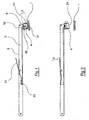
- la figure 1 est une vue d'ensemble d'un dispositif autonome de manipulation d'un composant électronique selon l'invention, dans une configuration correspondant à une position de préhension ;
- la figure 2 est une vue d'ensemble du dispositif de la figure 1, dans une configuration correspondant à une position de libération ;
- la figure 3 est une vue d'un deuxième mode de réalisation de l'invention ;
- la figure 4 est une vue de détail de la tête de préhension d'un dispositif selon l'invention.
- Figure 1 is an overview of an autonomous device for handling an electronic component according to the invention, in a configuration corresponding to a gripping position;
- Figure 2 is an overall view of the device of Figure 1, in a configuration corresponding to a release position;
- Figure 3 is a view of a second embodiment of the invention;
- Figure 4 is a detailed view of the gripping head of a device according to the invention.
L'invention concerne donc un dispositif autonome de manipulation de composants, mettant en oeuvre un aimant permanent et des moyens mécaniques permettant de désolidariser l'aimant et le composant, avec grande précision et sans contact manuel avec celui-ci.The invention therefore relates to an autonomous device handling device, using a permanent magnet and mechanical means for separating the magnet and the component, with great precision and without manual contact therewith.
Les figures 1 et 2 montrent un exemple d'un tel dispositif, respectivement dans les positions de préhension et de libération.Figures 1 and 2 show an example of such a device, respectively in the gripping and release positions.
Le dispositif autonome de manipulation d'un composant électronique 1 comprend un corps 2 et une tête de préhension 3 solidaires l'un de l'autre.The autonomous device for handling an electronic component 1 comprises a
On note, sur les figures 1 et 2, que le corps 2 et la tête de préhension forment un ensemble monobloc coudé, constitué par exemple de deux demi-coques plastiques solidarisées l'une à l'autre. Toutefois, selon un autre mode de réalisation envisageable, la tête pourrait être montée pivotante sur le corps du dispositif.It will be noted in FIGS. 1 and 2 that the
Il est aussi concevable que le corps et la tête de préhension s'étendent coaxialement.It is also conceivable that the body and the gripping head extend coaxially.
On note également que, selon une variante envisageable adaptable aux différents cas mentionnés ci-dessus, le corps 2 du dispositif peut être conçu de façon à le rendre télescopique.It is also noted that, in a variant that can be adapted to the different cases mentioned above, the
Selon l'invention, la tête de préhension 3 comprend un aimant permanent 4 et des moyens mécaniques de séparation mobiles l'un par rapport à l'autre de façon que le dispositif puisse prendre les positions illustrées par les figures 1 et 2.According to the invention, the gripping head 3 comprises a
Les dimensions ainsi que le matériau de l'aimant 4 sont prévus de façon à ce que celui-ci puisse supporter de 3 à 5 fois le poids du composant.The dimensions as well as the material of the
A titre indicatif, pour un macro-composant du type WISMO 3A pesant 11 grammes, l'aimant est donc prévu de façon que sa force d'attraction magnétique puisse maintenir un poids compris entre 33 et 55 grammes.As a guide, for a macro component WISMO type 3A weighing 11 grams, the magnet is provided so that its magnetic attraction force can maintain a weight of between 33 and 55 grams.
Tel qu'illustré sur la figure 1, le dispositif prend une position de préhension dans laquelle l'aimant 4 interagit par effet magnétique avec le composant, le maintenant en contact avec la tête de préhension 3.As shown in FIG. 1, the device takes a gripping position in which the
La figure 2 illustre le dispositif en position de libération, dans laquelle l'aimant 4 se trouve éloigné du composant 1, de façon à faire cesser l'interaction magnétique avec le composant.Figure 2 illustrates the device in release position, in which the
Selon le présent mode de réalisation, l'aimant 4 est mobile par rapport à la tête de préhension 3 entre la position de préhension, dans laquelle il se trouve au voisinage d'une surface de contact 31 de la tête 3, et la position de libération, dans laquelle il est éloignée de cette surface de contact 31 tandis que le composant 1 est en butée contre celle-ci.According to the present embodiment, the
Pour ce faire, l'aimant 4 est monté mobile à coulissement dans le corps creux 32 de la tête de préhension 3, l'extrémité débouchante de ce corps creux 32 formant la surface de contact 31 contre laquelle le composant 1 est susceptible de venir en butée.To do this, the
Il peut être prévu que l'aimant soit monté dans un support, celui-ci étant alors coulissant dans le corps creux de la tête de préhension.It can be provided that the magnet is mounted in a support, which is then sliding in the hollow body of the gripping head.
On comprend que la surface de contact 31 forme ainsi les moyens de séparation selon l'invention, puisque, lors du retrait de l'aimant 4 dans le corps creux 32 de la tête 3, la surface 31 maintient le composant dans une position fixe tandis que l'aimant s'éloigne du composant jusqu'à ce que l'interaction magnétique soit insuffisante pour maintenir le composant.It is understood that the
En position de libération du dispositif, l'effet magnétique susceptible de s'exercer sur le composant est fonction de la force magnétique intrinsèque de l'aimant, mais également de l'éloignement de celui-ci par rapport à l'extrémité de la tête de préhension. Selon un mode de réalisation particulier, la tête de préhension peut présenter, à l'opposé de son extrémité débouchante, une excroissance s'étendant dans le prolongement du corps creux, de façon à permettre une augmentation de l'éloignement de l'aimant en position de retrait par rapport à l'extrémité débouchante de la tête.In the release position of the device, the magnetic effect likely to be exerted on the component is a function of the intrinsic magnetic force of the magnet, but also the distance thereof from the end of the head grasping. According to a particular embodiment, the gripping head may have, opposite its emergent end, an outgrowth extending in the extension of the hollow body, so as to allow an increase in the distance of the magnet from withdrawal position relative to the open end of the head.
Dans la pratique, on cherchera à ce que la force résultante de l'attraction magnétique de l'aimant en position de libération soit inférieure à 10 % du poids du composant, ce qui, pour un macro-composant du type WISMO 3A tel qu'indiqué précédemment, correspond à une force inférieure à celle qui maintiendrait un poids de 1,1 gramme.In practice, it will be sought that the resultant force of the magnetic attraction of the magnet in the release position is less than 10% of the weight of the component, which, for a macro-component of the type WISMO 3A such as indicated previously, corresponds to a force lower than that which would maintain a weight of 1.1 gram.
Les moyens d'actionnement du mouvement de l'aimant sont constitués par un fil en nylon 5 solidarisé par une de ses extrémités à l'aimant 4, et par l'autre de ses extrémités à une gâchette 51, montée pivotante sur le corps 2 du dispositif.The means for actuating the movement of the magnet consist of a
Ce fil de nylon 5 est dévié, à partir de l'aimant 4, par un premier axe 52 faisant office de poulie au voisinage de l'aimant, puis par un deuxième axe 53, faisant également office de poulie, au voisinage de la gâchette 51.This
Un tel montage du fil 5 dans le dispositif entraîne un déplacement de l'aimant vers la position de libération lorsque qu'une action F est exercée sur la gâchette 4, tel qu'illustré par la figure 2.Such a mounting of the
On note que le fil de nylon pourra être réalisé en d'autres matières, ou être remplacé par un système de tringlettes rigides, de ressorts, de cames et/ou tout autre moyen connu permettant de déplacer une pièce mobile, dans d'autres modes de réalisation. Dans le cas où le corps du dispositif est télescopique, le fil de nylon (ou d'autres moyens envisageables) sont extensibles pour s'adapter aux variations de longueur d'un tel corps.Note that the nylon thread may be made of other materials, or be replaced by a system of rigid rods, springs, cams and / or any other known means for moving a moving part, in other modes of realization. In the case where the body of the device is telescopic, the wire nylon (or other conceivable means) are extensible to accommodate variations in the length of such a body.
On note également que selon une approche inverse, le montage des moyens d'actionnement pourrait être conçu de façon à déplacer l'aimant vers une position de préhension lorsqu'une action est exercée sur la gâchette.It is also noted that in a reverse approach, the mounting of the actuating means could be designed to move the magnet to a gripping position when an action is exerted on the trigger.
Selon le présent mode de réalisation, le dispositif comprend des moyens de rappel élastiques 6 agissant sur l'aimant 4 de façon à ramener celui-ci vers la position de préhension, en l'absence d'action exercée sur la gâchette 51.According to the present embodiment, the device comprises elastic return means 6 acting on the
Ces moyens de rappel élastiques sont constitués ici d'un ressort conique, qui présente l'avantage d'occuper un très faible encombrement (de l'ordre de 0,1 mm) à l'état comprimé, comme cela apparaît sur la figure 2.These elastic return means consist here of a conical spring, which has the advantage of occupying a very small footprint (of the order of 0.1 mm) in the compressed state, as shown in FIG. 2 .
Par ailleurs, comme cela apparaît sur la figure 4, il est prévu de revêtir la tête de préhension d'un bouchon 4 portant à son extrémité une membrane 411, dans le but notamment de :
- constituer une sorte de joint d'étanchéité évitant le dépôt de particules métalliques sur l'aimant ;
- éviter la détérioration du composant au contact de l'aimant, pouvant engendrer par exemple des rayures ;
- constituer un entrefer permettant de réduire localement le champ magnétique sur le composant, évitant ainsi une aimantation permanente du composant.
- to constitute a kind of seal avoiding the deposition of metal particles on the magnet;
- avoid deterioration of the component in contact with the magnet, which can cause for example scratches;
- provide an air gap to locally reduce the magnetic field on the component, thus avoiding permanent magnetization of the component.
Cette membrane 41 est réalisé en plastique ou en caoutchouc, avec une épaisseur comprise entre 0,1 et 0,5 mm.This
En référence à la figure 3 qui illustre un second mode de réalisation de l'invention, le mécanisme d'actionnement du mouvement de l'aimant est constitué d'une biellette 33 montée pivotante sur le corps 2 autour d'une axe 331.Referring to Figure 3 which illustrates a second embodiment of the invention, the mechanism for actuating the movement of the magnet consists of a
Cette biellette 33 un montée pivotante à l'une de ses extrémités sur un bouton poussoir 34 , et articulée, à son autre extrémité, sur un tige 35 solidaire de l'aimant 4.This
Comme cela à été précisé précédemment, la tête de préhension du dispositif peut présenter une excroissance 21 (représentée en traits pointillés), pour permettre d'augmenter la distance de retrait de l'aimant 4 à l'intérieur de la tête de préhension.As has been previously stated, the gripping head of the device may have an outgrowth 21 (shown in dashed lines), to allow to increase the withdrawal distance of the
Selon l'un ou l'autre des modes de réalisation qui viennent d'être décrits, le montage d'un tel dispositif est, à titre indicatif, réalisé en procédant notamment aux étapes suivantes :
- fondre l'extrémité du fil de nylon afin de former une petite bille;
- couper le fil nylon à une longueur déterminée ;
- enfiler le fil dans le ressort et dans un support d'aimant (percé en son centre);
- coller l'aimant dans son support en coinçant l'extrémité du fil à l'intérieur du support et en définissant la longueur finale du fil ;
- placer les axes dans une des demi-coques du corps ;
- placer l'ensemble aimant-support-ressort-fil-gâchette dans la demi-coque commençant par le côté aimant, puis, en maintenant le ressort en pression, placer la gâchette sur son axe ;
- placer la deuxième demi-coque sur la première, toujours en maintenant le ressort en pression ;
- visser les demi-coques entre elles.
- melt the end of the nylon thread to form a small ball;
- cut the nylon thread to a specified length;
- thread the wire into the spring and into a magnet holder (drilled in the center);
- stick the magnet in its support by wedging the end of the wire inside the support and defining the final length of the wire;
- place the axes in one of the half-shells of the body;
- place the magnet-support-spring-trigger-wire assembly into the half-shell starting with the magnet side, then, keeping the spring under pressure, place the trigger on its axis;
- place the second half-shell on the first one, always keeping the spring under pressure;
- screw the half-shells together.
Claims (15)
- An autonomous adjustable device for handling an electronic component (1), said device exhibiting a telescopic body (2) and a head (3) for gripping said component (1) by magnetic effect, said head comprising a permanent magnet (4) and mechanical separating means which are mobile in relation to one another in such a way that said device is able to assume at least two positions:- a gripping position in which said magnet (4) interacts with said component (1) in such a way as to maintain it in contact with a contact surface (31) of said head (3);- a releasing position in which said magnet (4) is remote in relation to said component (1) in such a way as to cause the magnetic interaction to cease,characterised in that said gripping head (3) is mounted on said body (2) in pivoting manner.
- Autonomous handling device according to Claim 1, characterised in that said mechanical separating means are mobile along said magnet and in that in the course of passing from said gripping position to said releasing position they exert a thrust on said component in such a way as to release it from said magnetic interaction.
- Autonomous handling device according to Claim 2, characterised in that said magnet is hollow, said mechanical separating means being mounted so as to be slidably mobile in relation to said magnet.
- Autonomous handling device according to Claim 1, characterised in that said magnet (4) is mobile in relation to said head (3) and in that:- in said gripping position said magnet (4) is in the vicinity of a contact surface (31) formed at the end of said head (3);- in said releasing position said magnet (4) is remote from said contact surface (31) in such a way as to release said component (1) from said magnetic interaction.
- Autonomous handling device according to Claim 4, characterised in that in said releasing position said component (1) comes into abutment against said contact surface (31).
- Autonomous handling device according to either of Claims 4 or 5, characterised in that said gripping head (3) comprises a hollow body (32), the issuing end of which forms said contact surface (31), and in which said magnet (4) is mounted so as to be slidably mobile.
- Autonomous handling device according to any one of Claims 1 to 6, characterised in that it comprises means (5) for actuation of a relative movement between said magnet (4) and said mechanical separating means.
- Autonomous handling device according to any one of Claims 4 to 7, characterised in that said actuation means (5) bring about the displacement of said magnet (4) towards said releasing position.
- Autonomous handling device according to any one of Claims 4 to 8, characterised in that said actuation means (5) bring about the displacement of said magnet (4) towards said gripping position.
- Autonomous handling device according to any one of Claims 1 to 9, characterised in that it comprises elastic return means (6) acting on said magnet (4) and/or on said separating means in such a way as to bring said device back into the position that it occupies in the absence of operation of said actuation means (5).
- Autonomous handling device according to Claims 8 and 10, characterised in that said elastic return means (6) act on said magnet (4) in such a way as to place said device in said gripping position.
- Autonomous handling device according to Claim 10 or according to Claim 11, characterised in that said elastic return means (6) comprise at least one conical spring.
- Autonomous handling device according to any one of Claims 6 to 12, characterised in that said actuation means (5) are operated by a trigger (51) positioned on said body (2).
- Autonomous handling device according to any one of Claims 5 to 13, characterised in that said gripping head (3) exhibits opposite said issuing end a protuberance extending into the continuation of said hollow body (32).
- Autonomous handling device according to any one of Claims 1 to 14, characterised in that said magnet (4) and/or said contact surface is/are coated with a membrane (411).
Applications Claiming Priority (3)
| Application Number | Priority Date | Filing Date | Title |
|---|---|---|---|
| FR0205027A FR2838916B1 (en) | 2002-04-22 | 2002-04-22 | AUTONOMOUS DEVICE FOR HANDLING AN ELECTRONIC COMPONENT BY MAGNETIC EFFECT |
| FR0205027 | 2002-04-22 | ||
| PCT/FR2003/001277 WO2003090506A1 (en) | 2002-04-22 | 2003-04-22 | Autonomous device for the magnetic handling of an electronic component |
Publications (2)
| Publication Number | Publication Date |
|---|---|
| EP1500318A1 EP1500318A1 (en) | 2005-01-26 |
| EP1500318B1 true EP1500318B1 (en) | 2006-06-14 |
Family
ID=28686261
Family Applications (1)
| Application Number | Title | Priority Date | Filing Date |
|---|---|---|---|
| EP03740653A Expired - Lifetime EP1500318B1 (en) | 2002-04-22 | 2003-04-22 | Autonomous device for the magnetic handling of an electronic component |
Country Status (8)
| Country | Link |
|---|---|
| US (1) | US20050218678A1 (en) |
| EP (1) | EP1500318B1 (en) |
| CN (1) | CN1291636C (en) |
| AT (1) | ATE330453T1 (en) |
| AU (1) | AU2003262398A1 (en) |
| DE (1) | DE60306143D1 (en) |
| FR (1) | FR2838916B1 (en) |
| WO (1) | WO2003090506A1 (en) |
Families Citing this family (2)
| Publication number | Priority date | Publication date | Assignee | Title |
|---|---|---|---|---|
| KR101304271B1 (en) * | 2009-07-13 | 2013-09-10 | (주)테크윙 | Handler and pick-and-place apparatus for inspection equipment of electric device and method for loading electric device onto loading position |
| US8544908B1 (en) * | 2012-05-22 | 2013-10-01 | Max See Industry Co., Ltd. | Electromagnetic pick-and-place device for use with processing apparatus |
Family Cites Families (10)
| Publication number | Priority date | Publication date | Assignee | Title |
|---|---|---|---|---|
| US2683618A (en) * | 1950-12-11 | 1954-07-13 | Louis Slovis | Automatic pickup device |
| GB738193A (en) * | 1953-03-03 | 1955-10-12 | Speed Tools Ltd | Improvements in or relating to tools for handling workpieces of iron and steel |
| US2834241A (en) * | 1957-03-22 | 1958-05-13 | Dale K Chowning | Magnetic socket wrench |
| US2970002A (en) * | 1959-01-20 | 1961-01-31 | Laviano Samuel | Magnetic pickup |
| US2976075A (en) * | 1959-07-17 | 1961-03-21 | Monarch Tool & Machinery Co | Magnetic pick-up device |
| US4620739A (en) * | 1984-12-17 | 1986-11-04 | William Coralline | Bingo chip bell |
| KR940010420A (en) * | 1992-10-30 | 1994-05-26 | 남희철 | plug |
| US5615920A (en) * | 1995-07-06 | 1997-04-01 | O'kane; John B. | Illuminated magnetic pickup tool |
| US5799999A (en) * | 1997-11-10 | 1998-09-01 | Cheyenne Tool, Llc | Magnetic retrieving tool |
| US6048073A (en) * | 1999-04-23 | 2000-04-11 | Shiao; Hsuan-Sen | Telescopic hand tool |
-
2002
- 2002-04-22 FR FR0205027A patent/FR2838916B1/en not_active Expired - Fee Related
-
2003
- 2003-04-22 WO PCT/FR2003/001277 patent/WO2003090506A1/en not_active Application Discontinuation
- 2003-04-22 EP EP03740653A patent/EP1500318B1/en not_active Expired - Lifetime
- 2003-04-22 US US10/512,350 patent/US20050218678A1/en not_active Abandoned
- 2003-04-22 DE DE60306143T patent/DE60306143D1/en not_active Expired - Lifetime
- 2003-04-22 AU AU2003262398A patent/AU2003262398A1/en not_active Abandoned
- 2003-04-22 AT AT03740653T patent/ATE330453T1/en not_active IP Right Cessation
- 2003-04-22 CN CNB038136082A patent/CN1291636C/en not_active Expired - Fee Related
Also Published As
| Publication number | Publication date |
|---|---|
| DE60306143D1 (en) | 2006-07-27 |
| FR2838916A1 (en) | 2003-10-24 |
| WO2003090506A1 (en) | 2003-10-30 |
| CN1659947A (en) | 2005-08-24 |
| CN1291636C (en) | 2006-12-20 |
| ATE330453T1 (en) | 2006-07-15 |
| US20050218678A1 (en) | 2005-10-06 |
| EP1500318A1 (en) | 2005-01-26 |
| FR2838916B1 (en) | 2005-08-12 |
| AU2003262398A1 (en) | 2003-11-03 |
Similar Documents
| Publication | Publication Date | Title |
|---|---|---|
| EP0838878A1 (en) | Spring contact element | |
| FR2979565A3 (en) | ELECTRIC TOOL WITH REPLACEABLE BLADE | |
| FR3025129A1 (en) | GRIPPING DEVICE | |
| EP0080960B1 (en) | Device with orientable jaws, adaptable to any support to assure in a stable way the holding, assembling, separating or keeping in position of workpieces of different shapes or dimensions | |
| EP1500318B1 (en) | Autonomous device for the magnetic handling of an electronic component | |
| EP0368777B1 (en) | Pneumatic gripper | |
| EP1642082A1 (en) | System for launching lightweight elements during festive events | |
| EP0347294B1 (en) | Robotic wrist, especially for joining a male or female electric connector to a complementary electric connector | |
| EP1855166B1 (en) | Tweezers and prehension sytem | |
| CH695871A5 (en) | Apparatus and method for testing electronic components. | |
| EP3546141A1 (en) | Device with cables for the application of equal forces on at least two points distant from one another | |
| EP1135979B1 (en) | Device for grasping and aligning an electronic component on a spindle | |
| FR3089143A1 (en) | Gripping device with adjustable magnetic heads | |
| FR2672835A1 (en) | Device for the temporary coupling of at least two members | |
| FR3006333A1 (en) | SUBLIMATION HEAD, AND METHOD FOR IMPLEMENTING THE SAME | |
| EP1559303B1 (en) | Device for extracting electronic components | |
| EP1652417B1 (en) | Prehensor, device for and method for positioning electronic components | |
| BE904143A (en) | DEVICE FOR ENTERING OBJECTS. | |
| WO2024061870A1 (en) | System for gripping a textile part | |
| FR3092513A1 (en) | Diaphragm gripping device and electromagnets | |
| WO2024061864A1 (en) | System for gripping a textile article having an unlockable, in particular magnetic, fastening | |
| EP0538155A1 (en) | Manufacturing process for an electromagnetic trip device with molded-in striker and trip device so obtained | |
| FR2686531A1 (en) | Device for handling cards, in particular those carrying advertising information, and card-stacking machine comprising such a device | |
| EP0327460A1 (en) | Automatically opening electric switch, in particular a differential interrupter | |
| FR2992014A1 (en) | Electromagnetic suction cup for use in access control field to maintain locked door, has magnetic material plate swinging from first state to second state during swinging of cup to locked and unlocked states, respectively |
Legal Events
| Date | Code | Title | Description |
|---|---|---|---|
| PUAI | Public reference made under article 153(3) epc to a published international application that has entered the european phase |
Free format text: ORIGINAL CODE: 0009012 |
|
| 17P | Request for examination filed |
Effective date: 20041119 |
|
| AK | Designated contracting states |
Kind code of ref document: A1 Designated state(s): AT BE BG CH CY CZ DE DK EE ES FI FR GB GR HU IE IT LI LU MC NL PT RO SE SI SK TR |
|
| AX | Request for extension of the european patent |
Extension state: AL LT LV MK |
|
| GRAP | Despatch of communication of intention to grant a patent |
Free format text: ORIGINAL CODE: EPIDOSNIGR1 |
|
| RAP1 | Party data changed (applicant data changed or rights of an application transferred) |
Owner name: WAVECOM |
|
| GRAS | Grant fee paid |
Free format text: ORIGINAL CODE: EPIDOSNIGR3 |
|
| GRAA | (expected) grant |
Free format text: ORIGINAL CODE: 0009210 |
|
| AK | Designated contracting states |
Kind code of ref document: B1 Designated state(s): AT BE BG CH CY CZ DE DK EE ES FI FR GB GR HU IE IT LI LU MC NL PT RO SE SI SK TR |
|
| PG25 | Lapsed in a contracting state [announced via postgrant information from national office to epo] |
Ref country code: AT Free format text: LAPSE BECAUSE OF FAILURE TO SUBMIT A TRANSLATION OF THE DESCRIPTION OR TO PAY THE FEE WITHIN THE PRESCRIBED TIME-LIMIT Effective date: 20060614 Ref country code: SI Free format text: LAPSE BECAUSE OF FAILURE TO SUBMIT A TRANSLATION OF THE DESCRIPTION OR TO PAY THE FEE WITHIN THE PRESCRIBED TIME-LIMIT Effective date: 20060614 Ref country code: RO Free format text: LAPSE BECAUSE OF FAILURE TO SUBMIT A TRANSLATION OF THE DESCRIPTION OR TO PAY THE FEE WITHIN THE PRESCRIBED TIME-LIMIT Effective date: 20060614 Ref country code: NL Free format text: LAPSE BECAUSE OF FAILURE TO SUBMIT A TRANSLATION OF THE DESCRIPTION OR TO PAY THE FEE WITHIN THE PRESCRIBED TIME-LIMIT Effective date: 20060614 Ref country code: IE Free format text: LAPSE BECAUSE OF FAILURE TO SUBMIT A TRANSLATION OF THE DESCRIPTION OR TO PAY THE FEE WITHIN THE PRESCRIBED TIME-LIMIT Effective date: 20060614 Ref country code: GB Free format text: LAPSE BECAUSE OF FAILURE TO SUBMIT A TRANSLATION OF THE DESCRIPTION OR TO PAY THE FEE WITHIN THE PRESCRIBED TIME-LIMIT Effective date: 20060614 Ref country code: IT Free format text: LAPSE BECAUSE OF FAILURE TO SUBMIT A TRANSLATION OF THE DESCRIPTION OR TO PAY THE FEE WITHIN THE PRESCRIBED TIME-LIMIT;WARNING: LAPSES OF ITALIAN PATENTS WITH EFFECTIVE DATE BEFORE 2007 MAY HAVE OCCURRED AT ANY TIME BEFORE 2007. THE CORRECT EFFECTIVE DATE MAY BE DIFFERENT FROM THE ONE RECORDED. Effective date: 20060614 Ref country code: CZ Free format text: LAPSE BECAUSE OF FAILURE TO SUBMIT A TRANSLATION OF THE DESCRIPTION OR TO PAY THE FEE WITHIN THE PRESCRIBED TIME-LIMIT Effective date: 20060614 Ref country code: SK Free format text: LAPSE BECAUSE OF FAILURE TO SUBMIT A TRANSLATION OF THE DESCRIPTION OR TO PAY THE FEE WITHIN THE PRESCRIBED TIME-LIMIT Effective date: 20060614 Ref country code: FI Free format text: LAPSE BECAUSE OF FAILURE TO SUBMIT A TRANSLATION OF THE DESCRIPTION OR TO PAY THE FEE WITHIN THE PRESCRIBED TIME-LIMIT Effective date: 20060614 |
|
| REG | Reference to a national code |
Ref country code: GB Ref legal event code: FG4D Free format text: NOT ENGLISH |
|
| REG | Reference to a national code |
Ref country code: CH Ref legal event code: EP |
|
| REG | Reference to a national code |
Ref country code: IE Ref legal event code: FG4D Free format text: LANGUAGE OF EP DOCUMENT: FRENCH |
|
| REF | Corresponds to: |
Ref document number: 60306143 Country of ref document: DE Date of ref document: 20060727 Kind code of ref document: P |
|
| PG25 | Lapsed in a contracting state [announced via postgrant information from national office to epo] |
Ref country code: SE Free format text: LAPSE BECAUSE OF FAILURE TO SUBMIT A TRANSLATION OF THE DESCRIPTION OR TO PAY THE FEE WITHIN THE PRESCRIBED TIME-LIMIT Effective date: 20060914 Ref country code: DK Free format text: LAPSE BECAUSE OF FAILURE TO SUBMIT A TRANSLATION OF THE DESCRIPTION OR TO PAY THE FEE WITHIN THE PRESCRIBED TIME-LIMIT Effective date: 20060914 |
|
| PG25 | Lapsed in a contracting state [announced via postgrant information from national office to epo] |
Ref country code: DE Free format text: LAPSE BECAUSE OF FAILURE TO SUBMIT A TRANSLATION OF THE DESCRIPTION OR TO PAY THE FEE WITHIN THE PRESCRIBED TIME-LIMIT Effective date: 20060915 |
|
| PG25 | Lapsed in a contracting state [announced via postgrant information from national office to epo] |
Ref country code: ES Free format text: LAPSE BECAUSE OF FAILURE TO SUBMIT A TRANSLATION OF THE DESCRIPTION OR TO PAY THE FEE WITHIN THE PRESCRIBED TIME-LIMIT Effective date: 20060925 |
|
| PG25 | Lapsed in a contracting state [announced via postgrant information from national office to epo] |
Ref country code: PT Free format text: LAPSE BECAUSE OF FAILURE TO SUBMIT A TRANSLATION OF THE DESCRIPTION OR TO PAY THE FEE WITHIN THE PRESCRIBED TIME-LIMIT Effective date: 20061114 |
|
| NLV1 | Nl: lapsed or annulled due to failure to fulfill the requirements of art. 29p and 29m of the patents act | ||
| GBV | Gb: ep patent (uk) treated as always having been void in accordance with gb section 77(7)/1977 [no translation filed] |
Effective date: 20060614 |
|
| REG | Reference to a national code |
Ref country code: IE Ref legal event code: FD4D |
|
| PLBE | No opposition filed within time limit |
Free format text: ORIGINAL CODE: 0009261 |
|
| STAA | Information on the status of an ep patent application or granted ep patent |
Free format text: STATUS: NO OPPOSITION FILED WITHIN TIME LIMIT |
|
| 26N | No opposition filed |
Effective date: 20070315 |
|
| REG | Reference to a national code |
Ref country code: CH Ref legal event code: PL |
|
| BERE | Be: lapsed |
Owner name: WAVECOM Effective date: 20070430 |
|
| PG25 | Lapsed in a contracting state [announced via postgrant information from national office to epo] |
Ref country code: CH Free format text: LAPSE BECAUSE OF NON-PAYMENT OF DUE FEES Effective date: 20070430 Ref country code: LI Free format text: LAPSE BECAUSE OF NON-PAYMENT OF DUE FEES Effective date: 20070430 |
|
| PG25 | Lapsed in a contracting state [announced via postgrant information from national office to epo] |
Ref country code: BE Free format text: LAPSE BECAUSE OF NON-PAYMENT OF DUE FEES Effective date: 20070430 |
|
| PG25 | Lapsed in a contracting state [announced via postgrant information from national office to epo] |
Ref country code: GR Free format text: LAPSE BECAUSE OF FAILURE TO SUBMIT A TRANSLATION OF THE DESCRIPTION OR TO PAY THE FEE WITHIN THE PRESCRIBED TIME-LIMIT Effective date: 20060915 |
|
| PG25 | Lapsed in a contracting state [announced via postgrant information from national office to epo] |
Ref country code: BG Free format text: LAPSE BECAUSE OF FAILURE TO SUBMIT A TRANSLATION OF THE DESCRIPTION OR TO PAY THE FEE WITHIN THE PRESCRIBED TIME-LIMIT Effective date: 20060914 |
|
| PG25 | Lapsed in a contracting state [announced via postgrant information from national office to epo] |
Ref country code: EE Free format text: LAPSE BECAUSE OF FAILURE TO SUBMIT A TRANSLATION OF THE DESCRIPTION OR TO PAY THE FEE WITHIN THE PRESCRIBED TIME-LIMIT Effective date: 20060614 |
|
| PG25 | Lapsed in a contracting state [announced via postgrant information from national office to epo] |
Ref country code: MC Free format text: LAPSE BECAUSE OF NON-PAYMENT OF DUE FEES Effective date: 20070430 |
|
| PG25 | Lapsed in a contracting state [announced via postgrant information from national office to epo] |
Ref country code: LU Free format text: LAPSE BECAUSE OF NON-PAYMENT OF DUE FEES Effective date: 20070422 Ref country code: CY Free format text: LAPSE BECAUSE OF FAILURE TO SUBMIT A TRANSLATION OF THE DESCRIPTION OR TO PAY THE FEE WITHIN THE PRESCRIBED TIME-LIMIT Effective date: 20060614 |
|
| PG25 | Lapsed in a contracting state [announced via postgrant information from national office to epo] |
Ref country code: HU Free format text: LAPSE BECAUSE OF FAILURE TO SUBMIT A TRANSLATION OF THE DESCRIPTION OR TO PAY THE FEE WITHIN THE PRESCRIBED TIME-LIMIT Effective date: 20061215 Ref country code: TR Free format text: LAPSE BECAUSE OF FAILURE TO SUBMIT A TRANSLATION OF THE DESCRIPTION OR TO PAY THE FEE WITHIN THE PRESCRIBED TIME-LIMIT Effective date: 20060614 |
|
| REG | Reference to a national code |
Ref country code: FR Ref legal event code: ST Effective date: 20091231 |
|
| PG25 | Lapsed in a contracting state [announced via postgrant information from national office to epo] |
Ref country code: FR Free format text: LAPSE BECAUSE OF NON-PAYMENT OF DUE FEES Effective date: 20091222 |
|
| PGFP | Annual fee paid to national office [announced via postgrant information from national office to epo] |
Ref country code: FR Payment date: 20080430 Year of fee payment: 6 |