EP1498604A1 - Windkraftanlage - Google Patents
Windkraftanlage Download PDFInfo
- Publication number
- EP1498604A1 EP1498604A1 EP03016188A EP03016188A EP1498604A1 EP 1498604 A1 EP1498604 A1 EP 1498604A1 EP 03016188 A EP03016188 A EP 03016188A EP 03016188 A EP03016188 A EP 03016188A EP 1498604 A1 EP1498604 A1 EP 1498604A1
- Authority
- EP
- European Patent Office
- Prior art keywords
- foundation
- power plant
- wind power
- plant according
- generator
- Prior art date
- Legal status (The legal status is an assumption and is not a legal conclusion. Google has not performed a legal analysis and makes no representation as to the accuracy of the status listed.)
- Granted
Links
- 238000010276 construction Methods 0.000 claims description 38
- 230000005540 biological transmission Effects 0.000 claims description 16
- 238000004146 energy storage Methods 0.000 claims description 9
- XLYOFNOQVPJJNP-UHFFFAOYSA-N water Substances O XLYOFNOQVPJJNP-UHFFFAOYSA-N 0.000 claims description 9
- 239000013590 bulk material Substances 0.000 claims description 4
- 230000000087 stabilizing effect Effects 0.000 claims description 4
- 230000008878 coupling Effects 0.000 claims description 2
- 238000010168 coupling process Methods 0.000 claims description 2
- 238000005859 coupling reaction Methods 0.000 claims description 2
- 238000004891 communication Methods 0.000 description 3
- 239000006262 metallic foam Substances 0.000 description 3
- 239000004576 sand Substances 0.000 description 3
- 230000006641 stabilisation Effects 0.000 description 3
- 238000011105 stabilization Methods 0.000 description 3
- 230000008901 benefit Effects 0.000 description 2
- 238000009434 installation Methods 0.000 description 2
- 238000004519 manufacturing process Methods 0.000 description 2
- 229910052782 aluminium Inorganic materials 0.000 description 1
- XAGFODPZIPBFFR-UHFFFAOYSA-N aluminium Chemical compound [Al] XAGFODPZIPBFFR-UHFFFAOYSA-N 0.000 description 1
- 230000009286 beneficial effect Effects 0.000 description 1
- 239000003651 drinking water Substances 0.000 description 1
- 235000020188 drinking water Nutrition 0.000 description 1
- 230000007257 malfunction Effects 0.000 description 1
- 239000000463 material Substances 0.000 description 1
- NJPPVKZQTLUDBO-UHFFFAOYSA-N novaluron Chemical compound C1=C(Cl)C(OC(F)(F)C(OC(F)(F)F)F)=CC=C1NC(=O)NC(=O)C1=C(F)C=CC=C1F NJPPVKZQTLUDBO-UHFFFAOYSA-N 0.000 description 1
Images


Classifications
-
- F—MECHANICAL ENGINEERING; LIGHTING; HEATING; WEAPONS; BLASTING
- F03—MACHINES OR ENGINES FOR LIQUIDS; WIND, SPRING, OR WEIGHT MOTORS; PRODUCING MECHANICAL POWER OR A REACTIVE PROPULSIVE THRUST, NOT OTHERWISE PROVIDED FOR
- F03D—WIND MOTORS
- F03D3/00—Wind motors with rotation axis substantially perpendicular to the air flow entering the rotor
- F03D3/005—Wind motors with rotation axis substantially perpendicular to the air flow entering the rotor the axis being vertical
-
- F—MECHANICAL ENGINEERING; LIGHTING; HEATING; WEAPONS; BLASTING
- F03—MACHINES OR ENGINES FOR LIQUIDS; WIND, SPRING, OR WEIGHT MOTORS; PRODUCING MECHANICAL POWER OR A REACTIVE PROPULSIVE THRUST, NOT OTHERWISE PROVIDED FOR
- F03D—WIND MOTORS
- F03D13/00—Assembly, mounting or commissioning of wind motors; Arrangements specially adapted for transporting wind motor components
- F03D13/10—Assembly of wind motors; Arrangements for erecting wind motors
-
- F—MECHANICAL ENGINEERING; LIGHTING; HEATING; WEAPONS; BLASTING
- F03—MACHINES OR ENGINES FOR LIQUIDS; WIND, SPRING, OR WEIGHT MOTORS; PRODUCING MECHANICAL POWER OR A REACTIVE PROPULSIVE THRUST, NOT OTHERWISE PROVIDED FOR
- F03D—WIND MOTORS
- F03D13/00—Assembly, mounting or commissioning of wind motors; Arrangements specially adapted for transporting wind motor components
- F03D13/20—Arrangements for mounting or supporting wind motors; Masts or towers for wind motors
-
- F—MECHANICAL ENGINEERING; LIGHTING; HEATING; WEAPONS; BLASTING
- F03—MACHINES OR ENGINES FOR LIQUIDS; WIND, SPRING, OR WEIGHT MOTORS; PRODUCING MECHANICAL POWER OR A REACTIVE PROPULSIVE THRUST, NOT OTHERWISE PROVIDED FOR
- F03D—WIND MOTORS
- F03D13/00—Assembly, mounting or commissioning of wind motors; Arrangements specially adapted for transporting wind motor components
- F03D13/20—Arrangements for mounting or supporting wind motors; Masts or towers for wind motors
- F03D13/22—Foundations specially adapted for wind motors
-
- F—MECHANICAL ENGINEERING; LIGHTING; HEATING; WEAPONS; BLASTING
- F03—MACHINES OR ENGINES FOR LIQUIDS; WIND, SPRING, OR WEIGHT MOTORS; PRODUCING MECHANICAL POWER OR A REACTIVE PROPULSIVE THRUST, NOT OTHERWISE PROVIDED FOR
- F03D—WIND MOTORS
- F03D9/00—Adaptations of wind motors for special use; Combinations of wind motors with apparatus driven thereby; Wind motors specially adapted for installation in particular locations
- F03D9/007—Adaptations of wind motors for special use; Combinations of wind motors with apparatus driven thereby; Wind motors specially adapted for installation in particular locations the wind motor being combined with means for converting solar radiation into useful energy
-
- F—MECHANICAL ENGINEERING; LIGHTING; HEATING; WEAPONS; BLASTING
- F05—INDEXING SCHEMES RELATING TO ENGINES OR PUMPS IN VARIOUS SUBCLASSES OF CLASSES F01-F04
- F05B—INDEXING SCHEME RELATING TO WIND, SPRING, WEIGHT, INERTIA OR LIKE MOTORS, TO MACHINES OR ENGINES FOR LIQUIDS COVERED BY SUBCLASSES F03B, F03D AND F03G
- F05B2240/00—Components
- F05B2240/10—Stators
- F05B2240/14—Casings, housings, nacelles, gondels or the like, protecting or supporting assemblies there within
- F05B2240/142—Casings, housings, nacelles, gondels or the like, protecting or supporting assemblies there within in the form of a standard ISO container
-
- F—MECHANICAL ENGINEERING; LIGHTING; HEATING; WEAPONS; BLASTING
- F05—INDEXING SCHEMES RELATING TO ENGINES OR PUMPS IN VARIOUS SUBCLASSES OF CLASSES F01-F04
- F05B—INDEXING SCHEME RELATING TO WIND, SPRING, WEIGHT, INERTIA OR LIKE MOTORS, TO MACHINES OR ENGINES FOR LIQUIDS COVERED BY SUBCLASSES F03B, F03D AND F03G
- F05B2240/00—Components
- F05B2240/90—Mounting on supporting structures or systems
- F05B2240/94—Mounting on supporting structures or systems on a movable wheeled structure
-
- F—MECHANICAL ENGINEERING; LIGHTING; HEATING; WEAPONS; BLASTING
- F05—INDEXING SCHEMES RELATING TO ENGINES OR PUMPS IN VARIOUS SUBCLASSES OF CLASSES F01-F04
- F05B—INDEXING SCHEME RELATING TO WIND, SPRING, WEIGHT, INERTIA OR LIKE MOTORS, TO MACHINES OR ENGINES FOR LIQUIDS COVERED BY SUBCLASSES F03B, F03D AND F03G
- F05B2240/00—Components
- F05B2240/90—Mounting on supporting structures or systems
- F05B2240/94—Mounting on supporting structures or systems on a movable wheeled structure
- F05B2240/941—Mounting on supporting structures or systems on a movable wheeled structure which is a land vehicle
-
- Y—GENERAL TAGGING OF NEW TECHNOLOGICAL DEVELOPMENTS; GENERAL TAGGING OF CROSS-SECTIONAL TECHNOLOGIES SPANNING OVER SEVERAL SECTIONS OF THE IPC; TECHNICAL SUBJECTS COVERED BY FORMER USPC CROSS-REFERENCE ART COLLECTIONS [XRACs] AND DIGESTS
- Y02—TECHNOLOGIES OR APPLICATIONS FOR MITIGATION OR ADAPTATION AGAINST CLIMATE CHANGE
- Y02E—REDUCTION OF GREENHOUSE GAS [GHG] EMISSIONS, RELATED TO ENERGY GENERATION, TRANSMISSION OR DISTRIBUTION
- Y02E10/00—Energy generation through renewable energy sources
- Y02E10/70—Wind energy
- Y02E10/72—Wind turbines with rotation axis in wind direction
-
- Y—GENERAL TAGGING OF NEW TECHNOLOGICAL DEVELOPMENTS; GENERAL TAGGING OF CROSS-SECTIONAL TECHNOLOGIES SPANNING OVER SEVERAL SECTIONS OF THE IPC; TECHNICAL SUBJECTS COVERED BY FORMER USPC CROSS-REFERENCE ART COLLECTIONS [XRACs] AND DIGESTS
- Y02—TECHNOLOGIES OR APPLICATIONS FOR MITIGATION OR ADAPTATION AGAINST CLIMATE CHANGE
- Y02E—REDUCTION OF GREENHOUSE GAS [GHG] EMISSIONS, RELATED TO ENERGY GENERATION, TRANSMISSION OR DISTRIBUTION
- Y02E10/00—Energy generation through renewable energy sources
- Y02E10/70—Wind energy
- Y02E10/728—Onshore wind turbines
-
- Y—GENERAL TAGGING OF NEW TECHNOLOGICAL DEVELOPMENTS; GENERAL TAGGING OF CROSS-SECTIONAL TECHNOLOGIES SPANNING OVER SEVERAL SECTIONS OF THE IPC; TECHNICAL SUBJECTS COVERED BY FORMER USPC CROSS-REFERENCE ART COLLECTIONS [XRACs] AND DIGESTS
- Y02—TECHNOLOGIES OR APPLICATIONS FOR MITIGATION OR ADAPTATION AGAINST CLIMATE CHANGE
- Y02E—REDUCTION OF GREENHOUSE GAS [GHG] EMISSIONS, RELATED TO ENERGY GENERATION, TRANSMISSION OR DISTRIBUTION
- Y02E10/00—Energy generation through renewable energy sources
- Y02E10/70—Wind energy
- Y02E10/74—Wind turbines with rotation axis perpendicular to the wind direction
Definitions
- the invention relates to a wind turbine, with at least a rotor blade, an associated stator construction, a generator and a foundation.
- Wind turbines of the design described above are well known and exemplified in DE 101 19 429 A1 or DE 100 65 548 A1.
- the invention is based on the technical problem, a Wind turbine of the design described above so continue to develop that building easy and fast This is also done in deporting areas the earth without corresponding know-how possible should be.
- the foundation is transportable and regular in its interior the generator or at least parts absorbs same.
- the generator is preferably on or in the foundation completely or partially attached or introduced into this.
- foundation and generator form mostly a pre-assembled transport unit.
- the foundation is the pedestal construction or essential parts thereof and also that includes at least one rotor blade for transport.
- the foundation serves as a storage container for essential parts of the wind turbine. simultaneously is the foundation of his primary task, namely in the assembled state of the wind turbine all forces acting on the stand construction take.
- the foundation takes over a double Function, namely to transport the wind turbine one Storage function as a quasi-transport container and after its mounting a stabilization function as Stabilization weight for the frame construction included Rotor blade.
- the foundation likes one or several folding arms for complaining and / or one or more receptacles for example bulk material and / or comparable stabilizing elements.
- the fold-out arms can be used, for example, with stones, Earth, sand or similar materials complained usually available indefinitely at the site are.
- the foundation thus obtains at the site the necessary weight to all on the Wind turbine to absorb acting forces. This makes it possible to design the foundation portable.
- the foldable arms, the receptacle or the other stabilizing elements that the Foundation in the assembled state of the wind turbine over has the necessary weight to keep it up complies with stabilizing function. It likes the receptacle or like the multiple receptacles outside the Foundation or be mounted in its interior. The latter offers the further advantage that the Receptacles during the transport of the wind turbine Components can absorb the same and after the Assembly as a receptacle for example bulk material or water.
- the engine unit may make sure that even in windless Times, for example, sufficient electrical energy for Is available to operate a water pump. Also is it is conceivable that the motor unit in combination with a Use winch for the construction of the wind turbine. Then the engine unit in combination with the Winch for the stand construction on the Foundation can be built.
- the electrical energy storage or the multiple accumulators may also serve windless times bridged. It is also possible with the help of such Energy storage communication systems within the Supply the foundation with electrical energy.
- the control unit responsible, which also operates the engine unit as well provides for the electrical charging of the energy storage. At the same time, the control unit ensures that the Energy storage by means of one or more solar cells is loaded. Likewise, the control unit takes over the corresponding charging function when resorting to a Motor unit and, where appropriate, external energy producers such as hydroelectric power plants, biogas plants, geothermal energy and others Wind turbines.
- the stator construction preferably has a transmission shaft for the rotor, wherein the Transmission shaft by means of a clutch or a Swivel joint is connected to a generator shaft.
- the Final operation therefore only requires the Production of the mechanical connection from the rotor over the Transmission wave up to the generator shaft. Because the Generator at least partially in or on the foundation is arranged, damage is caused by a manipulation not to be afraid. Rather, make foundation and Generator is a preassembled unit. Through this Variant also eliminates the difficulty of attaching the heavy generator on the rotor blades or head side the transmission shaft.
- the foundation contains in his Inside usually all for the operation of the Wind turbine minimally required components.
- the stand construction is completely or partly as well as the at least one rotor blade. It has proven especially as a foundation one to use standardized transport containers.
- a transport container a commercial Containers in the standardized dimensions are used, which logically simple and inexpensive can be transported.
- the Stand construction can preferably be hinged to the Foundation hinged or connected, preferably at its edge roof closure.
- a wind turbine is provided, The first thing about a transportable
- the foundation has its first to be at the site Adopting a sufficient stabilization function for a wind turbine gets needed weight. also become essential components of the wind turbine for the transport was taken in the foundation, which regularly designed as a standardized transport container. First At the place of installation, the individual components of the Wind turbine taken from the transport container or foundation.
- the roof side of the foundation is the stand construction constructed, the one or more rotor blades at their top wearing. It has proven particularly useful on so-called H-rotors recourse, as described in DE 100 65 548 A1 to be discribed. These H-rotors are characterized that they have an in the wind Substantially vertically arranged transmission shaft in Move rotations.
- the transmission wave works over the rotary joint or the coupling described on the likewise substantially vertically arranged generator shaft, without a reversal of direction got to. This simplifies the construction enormously and increases at the same time the efficiency.
- the specified pivot also not for power transmission used in energy production. In this case serves it as an assembly aid for the shaft or the total Generator.
- the generator is at least partially inside of the foundation is damaged during almost impossible to transport. In addition, will the generator is usually protected in the foundation while only the generator shaft is fully or partly out of the foundation. Thereby a long service life of the generator is achieved.
- the already flanged generator shaft with to connect the transmission shaft, which has a swivel joint usually happens with a shell clutch.
- the solar cells attached to the stator construction are, they automatically have one exposed location compared to the ground, so are present Rockfall or other damage effectively protected.
- the solar cells are usually in one Height of 3.4 or even more meters. Their functioning is So secured for a long time. This is especially important the background of interest, as the foundation or the Transport container additionally the function of a Shelter for people in their area can take over. In fact, there is always enough energy available to be able to make at least one emergency call. Of course it is also possible that with the help a water pump at least drinking water available stands. Here are the main benefits.
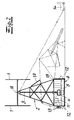
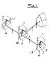
- a wind turbine is shown, the equipped with at least one rotor blade 1. in the Frame of the embodiment are two rotor blades. 1 provided, which of a common stand construction 2 are worn. Based on the figures recognizes one, that the rotor blades 1 each arranged vertically are and (each) form an H-rotor.
- the rotor blades 1 rotate by a distance common vertical axis A.
- This vertical axis A falls with the central axis of the stator structure 2 together.
- On the axis A can be found below the realized H rotor a transmission shaft 3 and then one Generator shaft 4, to which a generator 5 is connected.
- the stator structure 2 is supported by a foundation. 6 worn, which in the variant of FIGS. 1, 2 and 5 completely accommodates the generator 5 in its interior. Only the generator shaft 4 is guided to the outside. With reference to the alternative representation in FIG. 3, one recognizes that the foundation 6, the generator 5 at least partially receives. In the example shown is only one Foot 5 ', the generator 5 anchored in the foundation 6.
- the generator 5 is completely off enclosed the foundation 6, which as a standardized Transport container 6 is executed.
- the generator 5 takes the foundation or the transport container 6 the Rotor blades 1 and the stator construction 2 'for the Transport to a site in its interior.
- the generator 5 and parts of Stand construction 2 or the stand construction 2 Altogether in the foundation 6 additional components of Wind turbine housed.
- an alignment and measuring unit a voltage converter, an electric motor, a water pump Etc..
- Receiving trays 11 for example, bulk or water. These receptacles 11 can during transport the Take up rotor blades 1 and serve after installation the wind turbine at the construction site to stabilize the Stand construction 2. Basically like this too fold-out arms 12 contribute that merely hinted are.
- the foldable arms 12 are hinged to the Transport container 6 connected and can be on Fold the site horizontally onto the ground and with Complain earth, stones, sand etc. Both the foldable arms 12 and the filled receptacles 11 make sure that the on the roof of the Receptacle 6 constructed stand construction 2 with the head-side rotor blades 1 on the necessary stability features.
- FIGS. 1 and 2 make it clear as the stator structure 2 by means of a winch 13 on the foundation 6 build. This can be the Winch 13 of the inside of the transport container. 6 mounted motor unit 8 are driven. Also is it is conceivable to use the stand construction 2 with the help of a erect external vehicle 14.
- stator construction 2 is pivotal connected to the foundation or the transport container 6, wherein in the context of the illustration of FIG. 2 a roof and edge provided pivot 15 is used comes, which runs there as a stand framework Stand construction 2 folds up and absorbs Construction allows.
- Fig. 1 so proceeded that only the transmission shaft. 3 is swung, including another rotary joint or a Clutch 16 between the generator shaft 4 and the Transmission shaft 3 is provided.
- you can the clutch 16 not only in the hinged variants of Stand construction 2 according to FIGS. 1 and 2 be realized. But she finds consistently Use to the generator shaft 4 with the first on To connect construction site to be mounted transmission shaft 3.
- one or more solar cells 17 ensure that that even in windless times enough power for example to operate the control unit 10 and to load the electrical energy storage 9 is available.
- the two rotor blades 1 like stability and Weight reasons from a metal foam in its interior be constructed.
- This metal foam carries an outer Planking made of plastic or aluminum plates, which the Specify the profile of the rotor blades 1. It likes the Metal foam be prepared as in DE 199 39 518 A1 is described.
Landscapes
- Engineering & Computer Science (AREA)
- Life Sciences & Earth Sciences (AREA)
- Sustainable Development (AREA)
- Sustainable Energy (AREA)
- Chemical & Material Sciences (AREA)
- Combustion & Propulsion (AREA)
- Mechanical Engineering (AREA)
- General Engineering & Computer Science (AREA)
- Power Engineering (AREA)
- Wind Motors (AREA)
Abstract
Description
Claims (10)
- Windkraftanlage, mit wenigstens einem Rotorblatt (1), einer zugehörigen Ständerkonstruktion (2), einem Generator (5) und einem Fundament (6), dadurch gekennzeichnet, dass das Fundament (6) transportabel ausgebildet ist und vorzugsweise den Generator (5) oder wenigstens Teile desselben aufnimmt.
- Windkraftanlage nach Anspruch 1, dadurch gekennzeichnet, dass das Fundament (6) als Hohlkörper ausgebildet ist und neben dem Generator (5) bzw. Teilen desselben zusätzlich weitere Bestandteile der Windkraftanlage in unmontiertem Zustand aufnimmt.
- Windkraftanlage nach Anspruch 1 oder 2, dadurch gekennzeichnet, dass das Fundament (6) einen oder mehrere ausklappbare Arme (12) zum Beschweren und/oder eine oder mehrere Aufnahmewannen (11) für Schüttgut und/oder vergleichbare Stabilisierungselemente aufweist.
- Windkraftanlage nach einem der Ansprüche 1 bis 3, dadurch gekennzeichnet, dass das Fundament (6) ergänzend weitere Elemente wie ein Motoraggregat (8) einen elektrischen Energiespeicher (9) eine Steuerungseinheit (10), eine Ausricht- und Messeinheit, einen Spannungswandler, einen Elektromotor, eine Wasserpumpe etc. aufnimmt.
- Windkraftanlage nach einem der Ansprüche 1 bis 4, dadurch gekennzeichnet, dass das Fundament (6) in seinem Innern sämtliche für den Betrieb der Windkraftanlage erforderlichen Bauteile während des Transportes bevorratet.
- Windkraftanlage nach einem der Ansprüche 1 bis 5, dadurch gekennzeichnet, dass das Fundament (6) als standardisierter Transportbehälter (6), insbesondere Container (6), ausgebildet ist.
- Windkraftanlage nach einem der Ansprüche 1 bis 6, dadurch gekennzeichnet, dass die Ständerkonstruktion (2) eine Übertragungswelle (3)für den Rotor (1) aufweist, wobei die Übertragungswelle (3) über eine Kupplung (16) an eine Generatorwelle (4) angeschlossen ist.
- Windkraftanlage nach einem der Ansprüche 1 bis 7, dadurch gekennzeichnet, dass die Ständerkonstruktion (2) mittels einer Seilwinde (13) auf dem Fundament (6) errichtet wird.
- Windkraftanlage nach einem der Ansprüche 1 bis 8, dadurch gekennzeichnet, dass eine oder mehrere Solarzellen (17) an der Ständerkonstruktion (2) angebracht sind.
- Windkraftanlage nach einem der Ansprüche 1 bis 9, dadurch gekennzeichnet, dass die Ständerkonstruktion (2) klappbar an das Fundament (6) angelenkt ist.
Priority Applications (2)
| Application Number | Priority Date | Filing Date | Title |
|---|---|---|---|
| EP03016188A EP1498604B2 (de) | 2003-07-17 | 2003-07-17 | Windkraftanlage |
| DE50311869T DE50311869D1 (de) | 2003-07-17 | 2003-07-17 | Windkraftanlage |
Applications Claiming Priority (1)
| Application Number | Priority Date | Filing Date | Title |
|---|---|---|---|
| EP03016188A EP1498604B2 (de) | 2003-07-17 | 2003-07-17 | Windkraftanlage |
Publications (3)
| Publication Number | Publication Date |
|---|---|
| EP1498604A1 true EP1498604A1 (de) | 2005-01-19 |
| EP1498604B1 EP1498604B1 (de) | 2009-09-02 |
| EP1498604B2 EP1498604B2 (de) | 2012-10-31 |
Family
ID=33462138
Family Applications (1)
| Application Number | Title | Priority Date | Filing Date |
|---|---|---|---|
| EP03016188A Expired - Lifetime EP1498604B2 (de) | 2003-07-17 | 2003-07-17 | Windkraftanlage |
Country Status (2)
| Country | Link |
|---|---|
| EP (1) | EP1498604B2 (de) |
| DE (1) | DE50311869D1 (de) |
Cited By (6)
| Publication number | Priority date | Publication date | Assignee | Title |
|---|---|---|---|---|
| CN100374716C (zh) * | 2006-03-29 | 2008-03-12 | 严强 | 垂直轴风力发电机叶片安装方法 |
| WO2009010736A3 (en) * | 2007-07-17 | 2009-07-02 | Dale Vince | Vertical axis turbine |
| DE202010012748U1 (de) | 2010-09-20 | 2012-01-13 | Frank Draeger | Vorrichtung zum Erzeugen von elektrischer Energie aus einem strömenden Medium |
| DE102010045801A1 (de) | 2010-09-20 | 2012-03-22 | Frank Draeger | Vorrichtung zum Erzeugen von elektrischer Energie aus einem strömenden Medium |
| EP2435694A4 (de) * | 2009-05-26 | 2014-05-21 | Leviathan Energy Wind Lotus Ltd | Windturbinen mit zwei schaufeln und vertikaler achse |
| US8915697B2 (en) | 2008-08-22 | 2014-12-23 | Natural Power Concepts Inc. | Mobile wind turbine |
Citations (7)
| Publication number | Priority date | Publication date | Assignee | Title |
|---|---|---|---|---|
| DE375498C (de) * | 1923-05-15 | August Hobus | Fahrbarer Windmotor | |
| CA1134277A (en) * | 1980-09-15 | 1982-10-26 | Robert E. Kelland | Fluid operated apparatus or turbine |
| DE3405466A1 (de) * | 1984-02-16 | 1985-08-22 | Josef 7918 Illertissen Holzner | Mobile solarstation mit windkraft-generator kombinierbar |
| DE29510415U1 (de) * | 1995-07-03 | 1995-08-24 | ELMO GmbH, 46399 Bocholt | Mobile Stromerzeugungseinrichtung |
| GB2346655A (en) * | 1999-02-12 | 2000-08-16 | Richard Stuart Sutton | Gyrating mast wind-driven power converter |
| WO2003008803A1 (en) * | 2001-07-17 | 2003-01-30 | Ceap B.V. | Mobile wind and solar energy aggregate |
| EP1310671A1 (de) * | 2000-08-17 | 2003-05-14 | Hongsun Hua | Windturbine |
-
2003
- 2003-07-17 EP EP03016188A patent/EP1498604B2/de not_active Expired - Lifetime
- 2003-07-17 DE DE50311869T patent/DE50311869D1/de not_active Expired - Lifetime
Patent Citations (7)
| Publication number | Priority date | Publication date | Assignee | Title |
|---|---|---|---|---|
| DE375498C (de) * | 1923-05-15 | August Hobus | Fahrbarer Windmotor | |
| CA1134277A (en) * | 1980-09-15 | 1982-10-26 | Robert E. Kelland | Fluid operated apparatus or turbine |
| DE3405466A1 (de) * | 1984-02-16 | 1985-08-22 | Josef 7918 Illertissen Holzner | Mobile solarstation mit windkraft-generator kombinierbar |
| DE29510415U1 (de) * | 1995-07-03 | 1995-08-24 | ELMO GmbH, 46399 Bocholt | Mobile Stromerzeugungseinrichtung |
| GB2346655A (en) * | 1999-02-12 | 2000-08-16 | Richard Stuart Sutton | Gyrating mast wind-driven power converter |
| EP1310671A1 (de) * | 2000-08-17 | 2003-05-14 | Hongsun Hua | Windturbine |
| WO2003008803A1 (en) * | 2001-07-17 | 2003-01-30 | Ceap B.V. | Mobile wind and solar energy aggregate |
Cited By (7)
| Publication number | Priority date | Publication date | Assignee | Title |
|---|---|---|---|---|
| CN100374716C (zh) * | 2006-03-29 | 2008-03-12 | 严强 | 垂直轴风力发电机叶片安装方法 |
| WO2009010736A3 (en) * | 2007-07-17 | 2009-07-02 | Dale Vince | Vertical axis turbine |
| US20100194112A1 (en) * | 2007-07-17 | 2010-08-05 | Dale Vince | Vertical axis turbine |
| US8915697B2 (en) | 2008-08-22 | 2014-12-23 | Natural Power Concepts Inc. | Mobile wind turbine |
| EP2435694A4 (de) * | 2009-05-26 | 2014-05-21 | Leviathan Energy Wind Lotus Ltd | Windturbinen mit zwei schaufeln und vertikaler achse |
| DE202010012748U1 (de) | 2010-09-20 | 2012-01-13 | Frank Draeger | Vorrichtung zum Erzeugen von elektrischer Energie aus einem strömenden Medium |
| DE102010045801A1 (de) | 2010-09-20 | 2012-03-22 | Frank Draeger | Vorrichtung zum Erzeugen von elektrischer Energie aus einem strömenden Medium |
Also Published As
| Publication number | Publication date |
|---|---|
| EP1498604B2 (de) | 2012-10-31 |
| DE50311869D1 (de) | 2009-10-15 |
| EP1498604B1 (de) | 2009-09-02 |
Similar Documents
| Publication | Publication Date | Title |
|---|---|---|
| DE10245078B4 (de) | Windenergieanlage | |
| EP1613861B1 (de) | Versorgungseinheit für strom und wasser auf der basis erneuerbarer energien | |
| EP3406898B1 (de) | Gondelkomponente für eine windenergieanlage und verfahren zum montieren einer gondelkomponente | |
| EP2811160B1 (de) | Anlage zur Erzeugung von Windenergie auf See | |
| EP2673505A1 (de) | Turm für eine windkraftanlage | |
| DE19532880C1 (de) | Windkraftanlage zur Erzeugung elektrischer Energie | |
| DE29723861U1 (de) | Transportables Haus mit abklappbarem Dach | |
| EP0044390A2 (de) | Vorrichtung zur Erzeugung von elektrischer Energie aus Windenergie | |
| EP1498604B2 (de) | Windkraftanlage | |
| EP4347965B1 (de) | Energieraum | |
| DE102008047828A1 (de) | Fermenterbehälter für eine Biogasanlage | |
| DE202010017803U1 (de) | Wasserschneckenanlage | |
| DE2949447C2 (de) | Axialventilator, insbesondere zur Bodenfrostbekämpfung | |
| DE19526129A1 (de) | Selbstregelnde Windkraftanlage | |
| EP2461017A1 (de) | Archimedische Wasserschraubenanlage und Aufstellungsverfahren | |
| DE2524360A1 (de) | Windkraftwerk | |
| DE102005044123B4 (de) | Energiespeichervorrichtung | |
| DE102017116286A1 (de) | Drehbarer Zeltdachspitz | |
| EP4421308A1 (de) | Kleinspeicherkraftwerke zur energiespeicherung | |
| DE102008051274B3 (de) | Windenergieanlage mit einer Brückenkonstruktion | |
| EP4305245A1 (de) | Abdeckung einer bauteilöffnung eines bauteils insbesondere eines offshore-bauwerks | |
| EP3252305B1 (de) | Vorrichtung zum errichten einer windenergieanlage sowie verwendung der vorrichtung | |
| DE102004015294B3 (de) | Plakatträger | |
| DE102013108990A1 (de) | Einrichtung mit einer Saunakabine | |
| DE102023124721A1 (de) | Windkraftmodul zur Energieumwandlung an einem Objekt und Energiemodul zur Energieumwandlung und -speicherung aufweisend zumindest ein Windkraftmodul sowie Anordnung zur Energieumwandlung von zumindest einem Windkraftmodul und/oder zumindest einem Energiemodul an einem Objekt |
Legal Events
| Date | Code | Title | Description |
|---|---|---|---|
| PUAI | Public reference made under article 153(3) epc to a published international application that has entered the european phase |
Free format text: ORIGINAL CODE: 0009012 |
|
| AK | Designated contracting states |
Kind code of ref document: A1 Designated state(s): AT BE BG CH CY CZ DE DK EE ES FI FR GB GR HU IE IT LI LU MC NL PT RO SE SI SK TR |
|
| AX | Request for extension of the european patent |
Extension state: AL LT LV MK |
|
| 17P | Request for examination filed |
Effective date: 20050714 |
|
| AKX | Designation fees paid |
Designated state(s): DE ES GB NL |
|
| GRAP | Despatch of communication of intention to grant a patent |
Free format text: ORIGINAL CODE: EPIDOSNIGR1 |
|
| GRAS | Grant fee paid |
Free format text: ORIGINAL CODE: EPIDOSNIGR3 |
|
| GRAA | (expected) grant |
Free format text: ORIGINAL CODE: 0009210 |
|
| AK | Designated contracting states |
Kind code of ref document: B1 Designated state(s): DE ES GB NL |
|
| REF | Corresponds to: |
Ref document number: 50311869 Country of ref document: DE Date of ref document: 20091015 Kind code of ref document: P |
|
| NLV1 | Nl: lapsed or annulled due to failure to fulfill the requirements of art. 29p and 29m of the patents act | ||
| PG25 | Lapsed in a contracting state [announced via postgrant information from national office to epo] |
Ref country code: NL Free format text: LAPSE BECAUSE OF FAILURE TO SUBMIT A TRANSLATION OF THE DESCRIPTION OR TO PAY THE FEE WITHIN THE PRESCRIBED TIME-LIMIT Effective date: 20090902 |
|
| PG25 | Lapsed in a contracting state [announced via postgrant information from national office to epo] |
Ref country code: ES Free format text: LAPSE BECAUSE OF FAILURE TO SUBMIT A TRANSLATION OF THE DESCRIPTION OR TO PAY THE FEE WITHIN THE PRESCRIBED TIME-LIMIT Effective date: 20091213 |
|
| PLBI | Opposition filed |
Free format text: ORIGINAL CODE: 0009260 |
|
| PLAX | Notice of opposition and request to file observation + time limit sent |
Free format text: ORIGINAL CODE: EPIDOSNOBS2 |
|
| 26 | Opposition filed |
Opponent name: ENERCON GMBH Effective date: 20100601 |
|
| PLAF | Information modified related to communication of a notice of opposition and request to file observations + time limit |
Free format text: ORIGINAL CODE: EPIDOSCOBS2 |
|
| PLBB | Reply of patent proprietor to notice(s) of opposition received |
Free format text: ORIGINAL CODE: EPIDOSNOBS3 |
|
| GBPC | Gb: european patent ceased through non-payment of renewal fee |
Effective date: 20100717 |
|
| PG25 | Lapsed in a contracting state [announced via postgrant information from national office to epo] |
Ref country code: GB Free format text: LAPSE BECAUSE OF NON-PAYMENT OF DUE FEES Effective date: 20100717 |
|
| PLAB | Opposition data, opponent's data or that of the opponent's representative modified |
Free format text: ORIGINAL CODE: 0009299OPPO |
|
| R26 | Opposition filed (corrected) |
Opponent name: ENERCON GMBH Effective date: 20100601 |
|
| PUAH | Patent maintained in amended form |
Free format text: ORIGINAL CODE: 0009272 |
|
| STAA | Information on the status of an ep patent application or granted ep patent |
Free format text: STATUS: PATENT MAINTAINED AS AMENDED |
|
| 27A | Patent maintained in amended form |
Effective date: 20121031 |
|
| AK | Designated contracting states |
Kind code of ref document: B2 Designated state(s): DE ES GB NL |
|
| REG | Reference to a national code |
Ref country code: DE Ref legal event code: R102 Ref document number: 50311869 Country of ref document: DE Effective date: 20121031 |
|
| PGFP | Annual fee paid to national office [announced via postgrant information from national office to epo] |
Ref country code: DE Payment date: 20160707 Year of fee payment: 14 |
|
| REG | Reference to a national code |
Ref country code: DE Ref legal event code: R119 Ref document number: 50311869 Country of ref document: DE |
|
| PG25 | Lapsed in a contracting state [announced via postgrant information from national office to epo] |
Ref country code: DE Free format text: LAPSE BECAUSE OF NON-PAYMENT OF DUE FEES Effective date: 20180201 |