EP1498345A2 - Tragsäule für einen Fahrzueg-Karosserierahmen - Google Patents
Tragsäule für einen Fahrzueg-Karosserierahmen Download PDFInfo
- Publication number
- EP1498345A2 EP1498345A2 EP04016394A EP04016394A EP1498345A2 EP 1498345 A2 EP1498345 A2 EP 1498345A2 EP 04016394 A EP04016394 A EP 04016394A EP 04016394 A EP04016394 A EP 04016394A EP 1498345 A2 EP1498345 A2 EP 1498345A2
- Authority
- EP
- European Patent Office
- Prior art keywords
- support
- vehicle body
- body frame
- frame according
- column
- Prior art date
- Legal status (The legal status is an assumption and is not a legal conclusion. Google has not performed a legal analysis and makes no representation as to the accuracy of the status listed.)
- Granted
Links
Images


Classifications
-
- B—PERFORMING OPERATIONS; TRANSPORTING
- B62—LAND VEHICLES FOR TRAVELLING OTHERWISE THAN ON RAILS
- B62D—MOTOR VEHICLES; TRAILERS
- B62D25/00—Superstructure or monocoque structure sub-units; Parts or details thereof not otherwise provided for
- B62D25/04—Door pillars ; windshield pillars
-
- B—PERFORMING OPERATIONS; TRANSPORTING
- B62—LAND VEHICLES FOR TRAVELLING OTHERWISE THAN ON RAILS
- B62D—MOTOR VEHICLES; TRAILERS
- B62D25/00—Superstructure or monocoque structure sub-units; Parts or details thereof not otherwise provided for
- B62D25/02—Side panels
- B62D25/025—Side sills thereof
Definitions
- the invention relates to a support column for a vehicle body frame according to the preamble of claim 1.
- a support column for a body frame of a motor vehicle has a support beam which is hollow inside.
- the support beam has a trapezoidal cross-section.
- a tube is introduced to the stiffening and fastened there.
- This designed as a hollow profile support beam has additional devices inside for mounting the stiffening tube in the hollow profile.
- the voluminous stiffening tube and the fastening devices in the support carrier serve as additional deformation elements
- a disadvantage of such a complex structure in which a hollow body with another hollow body to increase the stability Deformation loads is provided that additional Fasteners for the stiffening tube e.g. in the form of Support profiles and Fixierblechen be required in the support beam.
- additional Fasteners for the stiffening tube e.g. in the form of Support profiles and Fixierblechen be required in the support beam.
- One Another disadvantage is that in such a with a Trapezoidal cross-section formed support support no attachments such as. Control units or belt parts are added to save space can because the support beam has a closed cross-sectional shape having.
- Another disadvantage is that the stiffening tube inside the support carrier occupies a large volume.
- the object of the invention is to show a support column, which is designed so that it can accommodate other attachments such as controllers, belt parts and sensors on the one hand and on the other hand is so stable that it is all accident-related requirements.
- a support column which has a support beam of a channel-shaped cross-section and the at least one tensile member clamps the support bracket between the upper and lower support so that the tensile member absorb the tensile stresses can that an accident act on the support beam.
- the advantage of the invention is that in the channel-shaped recess of the support column attachments, in particular control devices, belt parts or sensors can be accommodated. Another advantage is that the supporting column can be stabilized by the tension of the support support exactly in the direction that is affected by the external force in the accident.
- the trough-shaped support beam can be a robust casting and the tensile part a lightweight profile part.
- Hohloder solid profiles are suitable for the profiles.
- the hollow profile parts are constructed as extruded or Rollformprofiler having at least one tubular chamber.
- the profile parts may also have flanges, which serve for attachment to the support beam.
- the tensile part but also be a rope or a metal strip. It proves to be particularly advantageous if two tension parts are arranged on the support beam, which run as far as possible in the tub edge region of the support beam in the vehicle interior in order to be able to absorb the highest tensile stress from all components.
- such a construction with a one-piece but two-stranded drawstring can also be realized.
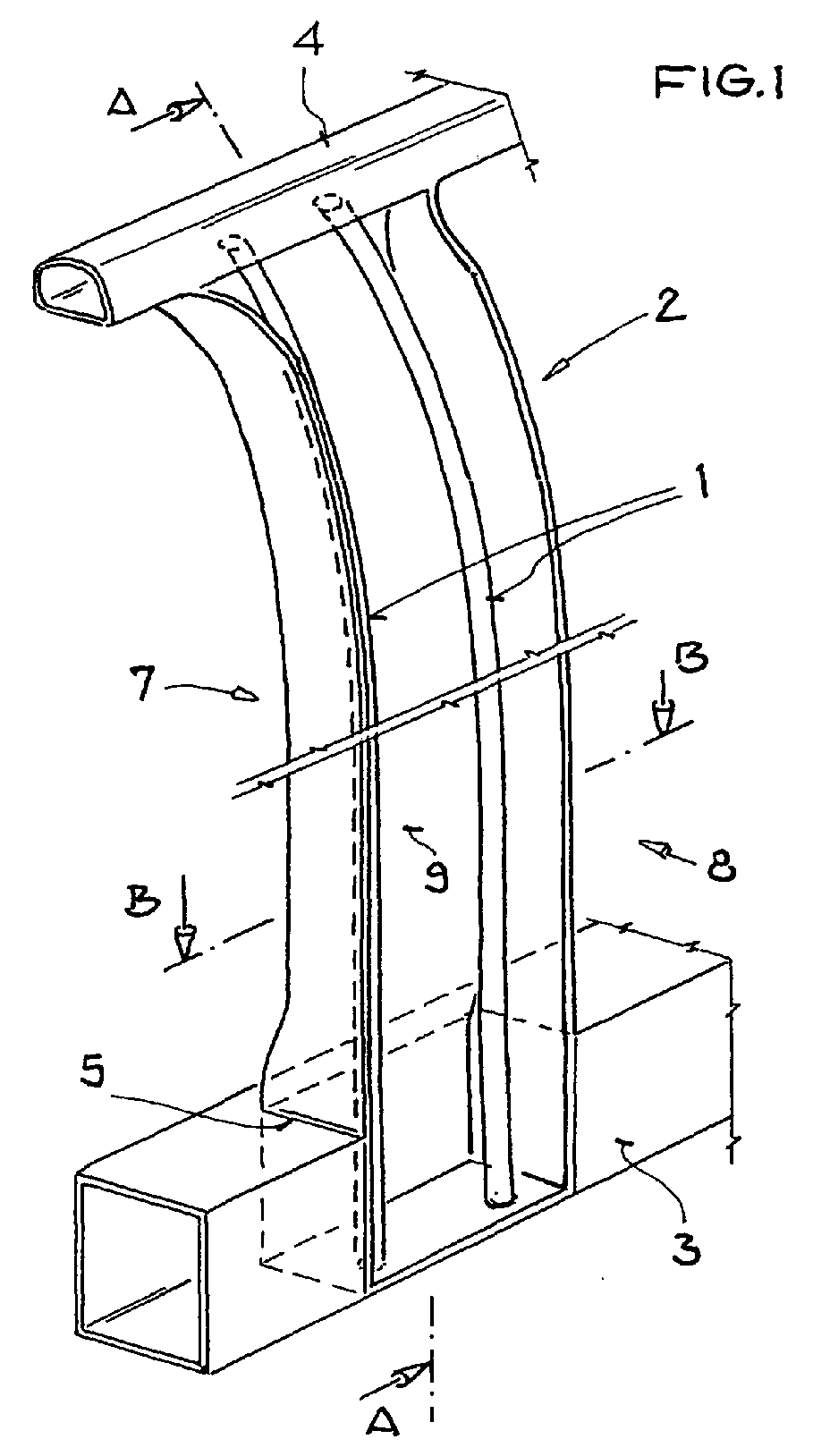
- Figure 1 shows a support column 2. In the embodiment, this forms later from the B-pillar of a motor vehicle.
- the support column 2 has a support beam 9 and two tension members 1 , which are arranged between an upper support 4 , which is part of the roof frame in the embodiment and a lower support 3 , which is formed by the sill.
- the support bracket 9 is braced laterally by the two rope-shaped tension members 1 .
- These tension members 1 serve to reduce a pressure-based deformation acting from the vehicle exterior 8 and to prevent the breakage of the support pillar 2 toward the vehicle interior 7 .
- the tension members 2 take part of the energy from the support bracket 9 and distribute it in other body parts.
- connection between the tension members 1 and the beams 3, 4 may be formed directly between the tension members 1 and the beams 3, 4 , or it may be formed indirectly between the tension members 1 via the support beam 9 and the beams 3, 4 , both the tension members 1 and the longitudinal members 3, 4 are fastened to the support beam 9 and there is no direct connection between the tension member 1 and the longitudinal members 3, 4 .
- This connection must be so strong that it can not be solved, for example, by a side crash.
- the sill 3 has a recess 5 , in which the support column 2 can be introduced so that it fills the recess 5 .
- the support column 2 is then welded to the lower support 3 .
- the support beam 9 and the one or more Werner / e be welded separately or else the one or the Glasteil / e is / are mounted in advance on the support beam 9 and then welded indirectly on the support bracket 9 on the sill 3 .
- other types of connections also serve the same purpose.
- the rope-shaped tension member 1 may have any shapes.
- the tension member 1 may be a wire rope, a rod or a thin tube that is stretched between the sill 3 and the roof rack 4 .
- several tension members 1 can be used.
- the tension members 1 are guided in the support bracket 9 .
- Important in the tensile part 1 is that it is so tense that it distributes the forces and stresses of the support beam 9 in other body parts.
- the conversion of the impact energy during the side crash into transformation energy in the tensile part 1 itself is not absolutely necessary. It is important for the tension part 1 that it absorbs and distributes the stresses created by the load.
- FIG. 2 shows a section through the plane AA of Figure 1.
- the tension member 1 is embedded in the support bracket 9 .
- Both parts 1, 9 are part of the support column 2.
- the tension member 1 extends over the entire height of the support column 2 and forms a positive connection with sill 3 and roof frame 4.
- a tension member 1 has the task of a part of the side impact in the Supporting column 2 absorb tensile stresses and distribute and thereby support the support beam 9 and relieve.
- This external, horizontal force is represented by the arrow 6 in FIG.
- FIG 3 shows a sectional view through the BB level of the support column 2 of Figure 1.
- a closing part 12 and a side part 10 is attached, as is usual in a vehicle B-pillar.
- the tension members 1 are constructed as hollow profiles, in particular as a tube. Alternatively, solid profiles, in particular rods or ropes can be used.
- the tension members 1 are integrated here by pouring directly into the support beam 9 of the support column 2 . It is therefore no additional operation necessary to connect the tension members 1 with the support beam 9 or at least in the support beam 2 to lead.
- the tension members 1 are arranged on the loaded by train side of the support column 2 . In this illustration, it is clear that the support beam 9 has a channel shape.
- a bending axis 10 of the B pillar is shown around which the B pillar 2 bends when a side crash based force 6 acts on the B pillar 2 from the outside. Due to the tension of the tension members 1 on the upper and lower carrier 4, 3, a counterforce 14 is generated, which reduces a folding of the support column 2 about the bending axis 10 .
- FIG. 4 shows a further sectional illustration.
- This shows another embodiment of the tension member.
- 1 In this tensile part 1 is a one-piece Rollformprofil 15th
- the one-piece Rollformprofil 15 has two tubular portions 13 , which are mainly responsible for the tension of the B-pillar.
- the one-piece Rollformprofil 15 can be mounted either directly on the sill or on the roof frame, with welding is particularly well suited as a connection.
- the attachment of the support column 2 tensioning tension member 1 can also be done indirectly.
- the tension member 1 is attached to the support bracket 9 via connecting means 16 and the support bracket 9 attached to the upper and lower support.
- the connecting means 16 may be, for example, rivets, adhesive or a welded connection.
- the Rollformprofil also has a groove-shaped formation, which is inserted into the trough-shaped configuration of the support beam, so that additional components can be mounted to save space in the support bracket 9 .
- the advantage of the one-piece construction 15 of two tubular sections 13 is that only one part has to be processed, which has a favorable effect on the production costs. Otherwise, the support beam 9 is covered again from the outside by the closing part 12 and the side part 11 .
- the tension members 1 are constructed by two individual riveted, welded or glued roll or extruded profiles around, in contrast to the one-piece variant 15 of Figure 4 , to be able to meet the loads occurring more flexible.
- the tension members 1 flanges on which connecting means 16 can be attached, which allow easy attachment to the support beam 9 over its entire length.
- FIG. 6 shows two glued-in flangeless tension parts 1, which are glued directly into the support beam 9 .
- the tension members 1 consist of profile parts. Without a joining flange, more precise tolerances can be maintained when manufacturing the profile parts.
- the support bracket 9 has two receiving devices 17 , in which the tension members 1 can be inserted and glued.
- FIG. 7 shows a tensile part 1, which is designed as a band 18 .
- the tension member 1 is not made of a rope, hollow or solid profile, but from a flat consisting of sheet tension band 18 , which can also absorb the tension and distribute.
- the support column 2 between the upper and lower support 4, 3 is braced. This offers the possibility of mounting attachments (control unit, belt, sensor, etc.) in the support bracket, in particular in the groove-shaped recess.
- the one-piece embodiment of the drawstring 18 shown in the figure shows two strands extending from the lower support 3 to the upper support 4 .
- transverse webs 19 are ladder-shaped connected by transverse webs 19 , but these transverse webs are optional, for example, to prevent the unfolding of a trough-shaped cross-section having B-pillar 2, in particular of the support bracket 9, in the event of an accident.
- FIG 8 shows a section through the plane AA of the support column 2 with tension band 18 , as shown in Figure 7.
- the support column 2 has a groove-shaped support support 9 .
- the gutter bulge of the support beam is covered in the outer region 8 of the vehicle by a closing part 12 and a side part 11 , wherein the side part 11 and the closing part 12 covers.
- In the interior region 7 of the vehicle 9 are in the trough-shaped recess of the support bracket attachments 20 , such as control units and belt tensioners, which can be accommodated here to save space.
- the one-piece drawstring 18 which is placed like a cover on the channel-shaped recess in the vehicle interior.
- FIG. 9 shows a longitudinal section through the support carrier 9 with drawstring 18 .
- the drawstring 18 in particular the two strands which extend from the lower support 3 to the upper support 4 , is firmly and positively connected to these two supports 3, 4 .
- the drawstring 18 takes the tensile loads of the support beam 9 clamped like a net. This prevents that the B-pillar bends too much into the vehicle interior or even breaks through.
- tension members 1, 15, 18 are integrated in or on the support bracket 9 and the vehicle run furthest inside to accommodate the highest tensile stresses of all components.
- the tension members 1, 15, 18 may consist of a wide variety of metals, in particular aluminum or steel, as well as plastic or fiber composites.
- the support beam is advantageously a casting to a high strength
- other parts in particular profile parts are used instead of a casting.
Landscapes
- Engineering & Computer Science (AREA)
- Chemical & Material Sciences (AREA)
- Combustion & Propulsion (AREA)
- Transportation (AREA)
- Mechanical Engineering (AREA)
- Body Structure For Vehicles (AREA)
Abstract
Description
- Figur 1:
- Tragsäule mit zwei seilförmigen Spannvorrichtungen zwischen einem oberen und einem unteren Träger
- Figur 2:
- Längsschnitt durch eine Tragsäule gemäß Figur 1
- Figur 3:
- Querschnitt durch eine Tragsäule gemäß Figur 1
- Figur 4:
- Tragsäule mit einem einstückigen Zugprofil mit Flansch
- Figur 5:
- Tragsäule mit einem zweistückigen Zugprofil mit Flansch
- Figur 6:
- Tragsäule mit einem Zugprofil ohne Flansch
- Figur 7:
- Tragsäule mit Zugband.
- Figur 8:
- Querschnitt durch eine Tragsäule mit Zugband
- Figur 9:
- Längsschnitt durch eine Tragsäule mit Zugband
Claims (13)
- Tragsäule (2) für einen Fahrzeug-Karosserierahmendadurch gekennzeichnet, dassdie zwischen einem unteren Träger (3) und einem oberen Träger (4) angeordnet ist und dieeinen Stützträger (9) aufweist,der Stützträger (9) einen rinnenförmigen Querschnitt hat unddie Tragsäule (2) mindestens ein Zugteil (1, 15, 18) aufweist, daszwischen dem unteren und oberen Träger (3, 4) gespannt ist und daseine unfallbedingte Zugbelastung aus dem Stützträger (9) aufnimmt.
- Tragsäule (2) für einen Fahrzeug-Karosserierahmen nach Patentanspruch 1, dadurch gekennzeichnet, dass
zwei Zugteile (1) parallel zueinander in der Tragsäule (2) angeordnet sind. - Tragsäule (2) für einen Fahrzeug-Karosserierahmen nach Patentanspruch 1 oder 2, dadurch gekennzeichnet, dass
ein Zugteil (1) ein Seil ist. - Tragsäule (2) für einen Fahrzeug-Karosserierahmen nach Patentanspruch 1 oder 2, dadurch gekennzeichnet, dass
ein Zugteil (1) ein Blechband (18) ist. - Tragsäule (2) für einen Fahrzeug-Karosserierahmen nach Patentanspruch 1, dadurch gekennzeichnet, dass
das Zugteil (1) ein leiterförmig ausgebildetes Blechband (18) ist. - Tragsäule für einen Fahrzeug-Karosserierahmen nach Patentanspruch 1, dadurch gekennzeichnet, dass
das Zugteil (1) ein Profilteil (15) ist. - Tragsäule (2) für einen Fahrzeug-Karosserierahmen nach Patentanspruch 6, dadurch gekennzeichnet, dass
das Zugteil (1) ein Vollprofilteil, insbesondere eine Stange ist. - Tragsäule (2) für einen Fahrzeug-Karosserierahmen nach Patentanspruch 6, dadurch gekennzeichnet, dass
das Zugteil (1, 15) ein Hohlprofilteil ist. - Tragsäule (2) für einen Fahrzeug-Karosserierahmen nach Patentanspruch 8, dadurch gekennzeichnet, dass
das Zugteil (1, 15) ein Rohr ist. - Tragsäule (2) für einen Fahrzeug-Karosserierahmen nach Patentanspruch 8, dadurch gekennzeichnet, dass
das Zugteil (1, 15) ein Strangpressprofilteil ist. - Tragsäule (2) für einen Fahrzeug-Karosserierahmen nach Patentanspruch 8, dadurch gekennzeichnet, dass
das Zugteil (1, 15) ein Rollformprofilteil ist. - Tragsäule (2) für einen Fahrzeug-Karosserierahmen nach Patentanspruch 8, dadurch gekennzeichnet, dass
das Hohlprofilteil (1) Flansche aufweist, die zur Befestigung an die Tragsäule (2) dienen. - Tragsäule (2) für einen Fahrzeug-Karosserierahmen nach Patentanspruch 1, dadurch gekennzeichnet, dass
das Zugteil (1, 15) ein Mehrkammerprofilteil ist, wobei mindestens zwei Kammern parallel, zwischen dem unteren und oberen Träger (4, 3) verlaufend, angeordnet sind.
Applications Claiming Priority (2)
| Application Number | Priority Date | Filing Date | Title |
|---|---|---|---|
| DE10332633 | 2003-07-18 | ||
| DE2003132633 DE10332633B4 (de) | 2003-07-18 | 2003-07-18 | Tragsäule für einen Fahrzeug-Karosserierahmen |
Publications (3)
| Publication Number | Publication Date |
|---|---|
| EP1498345A2 true EP1498345A2 (de) | 2005-01-19 |
| EP1498345A3 EP1498345A3 (de) | 2005-08-31 |
| EP1498345B1 EP1498345B1 (de) | 2011-01-19 |
Family
ID=33461981
Family Applications (1)
| Application Number | Title | Priority Date | Filing Date |
|---|---|---|---|
| EP20040016394 Expired - Lifetime EP1498345B1 (de) | 2003-07-18 | 2004-07-13 | Tragsäule für einen Fahrzueg-Karosserierahmen |
Country Status (3)
| Country | Link |
|---|---|
| EP (1) | EP1498345B1 (de) |
| DE (2) | DE10332633B4 (de) |
| ES (1) | ES2359812T3 (de) |
Cited By (9)
| Publication number | Priority date | Publication date | Assignee | Title |
|---|---|---|---|---|
| EP1839966A1 (de) * | 2006-03-24 | 2007-10-03 | GM Global Technology Operations, Inc. | Vorrichtung zur Halterung einer Gurtspanneinrichtung |
| ITBO20090492A1 (it) * | 2009-07-28 | 2011-01-29 | Ferrari Spa | Telaio di un veicolo provvisto di un montante centrale estruso |
| EP2383170A1 (de) * | 2009-07-02 | 2011-11-02 | Basf Se | Vorrichtung zur Verstärkung von Hohlprofilen oder U-Profilen sowie damit verstärktes Profil |
| EP2527232A1 (de) * | 2011-05-25 | 2012-11-28 | Bayerische Motoren Werke Aktiengesellschaft | Aluminiumdruckgussteil |
| US20140346816A1 (en) * | 2013-05-21 | 2014-11-27 | Ford Global Technologies, Llc | Vehicle frame rail and pillar connection |
| WO2015071412A1 (en) * | 2013-11-15 | 2015-05-21 | Autotech Engineering A.I.E. | Beams with u-shaped cross-section |
| WO2015107227A2 (fr) | 2014-01-20 | 2015-07-23 | Autotech Engineering, A.I.E. | Dispositif de structure de carrosserie de véhicules |
| CN104843076A (zh) * | 2015-04-28 | 2015-08-19 | 杭州云乐车辆技术有限公司 | 模块化分区式白车身 |
| US9751568B2 (en) | 2015-12-07 | 2017-09-05 | Honda Motor Co., Ltd. | Body frame structure for a vehicle |
Families Citing this family (7)
| Publication number | Priority date | Publication date | Assignee | Title |
|---|---|---|---|---|
| DE102006011808B4 (de) * | 2006-03-15 | 2008-07-17 | Audi Ag | Einrichtung zur Erhöhung der Steifigkeit von Hohlprofilen |
| DE102006041111B4 (de) * | 2006-09-01 | 2013-01-03 | Audi Ag | Befestigungsanordnung einer Haltekonsole an einem Trägerteil einer Kraftwagenkarosserie |
| DE102007032319B4 (de) * | 2007-07-11 | 2011-01-20 | Bayerische Motoren Werke Aktiengesellschaft | Verstärkungsträger einer Fahrzeugkarosserie |
| DE102008024274A1 (de) * | 2008-05-20 | 2009-11-26 | Wilhelm Karmann Gmbh | Säule einer Karosserie eines Fahrzeugs |
| DE102010063762A1 (de) * | 2010-12-21 | 2012-06-21 | Bayerische Motoren Werke Aktiengesellschaft | Rahmenstruktur für eine Fahrzeugkarosserie |
| DE102013214717A1 (de) * | 2013-07-29 | 2015-01-29 | Bayerische Motoren Werke Aktiengesellschaft | Biegeträger aus faserverstärktem Kunststoff einer Kraftfahrzeugkarosserie |
| JP7392702B2 (ja) | 2021-10-28 | 2023-12-06 | トヨタ自動車株式会社 | 車両側部構造 |
Family Cites Families (8)
| Publication number | Priority date | Publication date | Assignee | Title |
|---|---|---|---|---|
| AT139335B (de) * | 1933-06-06 | 1934-11-10 | Maximilian Ing Sachs | Eiserner Träger. |
| EP0561840B1 (de) * | 1990-12-20 | 1994-08-24 | Audi Ag | Mittelsäule an einer karosserie eines personenkraftwagens |
| DE4208408C2 (de) * | 1992-03-16 | 1994-01-13 | Steyr Daimler Puch Ag | Kraftfahrzeugkörper mit Seitenschutz |
| JP3594145B2 (ja) * | 1995-09-04 | 2004-11-24 | 本田技研工業株式会社 | センタピラーの衝撃吸収構造 |
| DE19914344A1 (de) * | 1998-04-01 | 1999-11-25 | Fraunhofer Ges Forschung | Tragstruktur, insbesondere Seitenaufprallträger für Fahrzeuge |
| KR20010049950A (ko) * | 1999-08-05 | 2001-06-15 | 제임스 이. 미러 | 차체의 프레임구조 |
| DE19954647C2 (de) * | 1999-11-13 | 2003-12-11 | Benteler Werke Ag | Seitenaufprallträger |
| DE10117009B4 (de) * | 2001-04-05 | 2005-04-21 | Daimlerchrysler Ag | Tragsäule für einen Karosserierahmen eines Kraftfahrzeugs |
-
2003
- 2003-07-18 DE DE2003132633 patent/DE10332633B4/de not_active Expired - Lifetime
-
2004
- 2004-07-13 EP EP20040016394 patent/EP1498345B1/de not_active Expired - Lifetime
- 2004-07-13 DE DE200450012121 patent/DE502004012121D1/de not_active Expired - Lifetime
- 2004-07-13 ES ES04016394T patent/ES2359812T3/es not_active Expired - Lifetime
Cited By (22)
| Publication number | Priority date | Publication date | Assignee | Title |
|---|---|---|---|---|
| EP1839966A1 (de) * | 2006-03-24 | 2007-10-03 | GM Global Technology Operations, Inc. | Vorrichtung zur Halterung einer Gurtspanneinrichtung |
| EP2383170A1 (de) * | 2009-07-02 | 2011-11-02 | Basf Se | Vorrichtung zur Verstärkung von Hohlprofilen oder U-Profilen sowie damit verstärktes Profil |
| US8272682B2 (en) | 2009-07-28 | 2012-09-25 | Studio Torta S.p.A. | Chassis of a vehicle provided with an extruded central pillar |
| ITBO20090492A1 (it) * | 2009-07-28 | 2011-01-29 | Ferrari Spa | Telaio di un veicolo provvisto di un montante centrale estruso |
| EP2279928A2 (de) | 2009-07-28 | 2011-02-02 | Ferrari S.p.A. | Fahrzeugrahmen mit einer extrudierten Mittelsäule |
| EP2279928A3 (de) * | 2009-07-28 | 2011-09-07 | Ferrari S.p.A. | Fahrzeugrahmen mit einer extrudierten Mittelsäule |
| EP2527232A1 (de) * | 2011-05-25 | 2012-11-28 | Bayerische Motoren Werke Aktiengesellschaft | Aluminiumdruckgussteil |
| US9139235B2 (en) * | 2013-05-21 | 2015-09-22 | Ford Global Technologies, Llc | Vehicle frame rail and pillar connection |
| US20140346816A1 (en) * | 2013-05-21 | 2014-11-27 | Ford Global Technologies, Llc | Vehicle frame rail and pillar connection |
| WO2015071412A1 (en) * | 2013-11-15 | 2015-05-21 | Autotech Engineering A.I.E. | Beams with u-shaped cross-section |
| CN105722745B (zh) * | 2013-11-15 | 2018-10-26 | 自动工程公司 | 具有u形横截面的横梁 |
| WO2015071444A3 (fr) * | 2013-11-15 | 2015-09-24 | Autotech Engineering, A.I.E. | Poutre pour la réalisation d'une ossature métallique |
| CN105722746A (zh) * | 2013-11-15 | 2016-06-29 | 自动工程公司 | 用于制造金属框架的梁 |
| CN105722745A (zh) * | 2013-11-15 | 2016-06-29 | 自动工程公司 | 具有u形横截面的横梁 |
| US10279844B2 (en) | 2013-11-15 | 2019-05-07 | Autotech Engineering A.I.E. | Beams with U-shaped cross-section |
| US9849916B2 (en) | 2013-11-15 | 2017-12-26 | Autotech Engineering A.I.E. | Beams with U-shaped cross-section |
| CN105722746B (zh) * | 2013-11-15 | 2018-06-01 | 自动工程公司 | 用于制造金属框架的梁 |
| US10023237B2 (en) | 2013-11-15 | 2018-07-17 | Autotech Engineering A.I.E. | Beam for producing a metal framework |
| WO2015107227A2 (fr) | 2014-01-20 | 2015-07-23 | Autotech Engineering, A.I.E. | Dispositif de structure de carrosserie de véhicules |
| US9828034B2 (en) | 2014-01-20 | 2017-11-28 | Autotech Engineering A.I.E. | Vehicle bodywork structure device |
| CN104843076A (zh) * | 2015-04-28 | 2015-08-19 | 杭州云乐车辆技术有限公司 | 模块化分区式白车身 |
| US9751568B2 (en) | 2015-12-07 | 2017-09-05 | Honda Motor Co., Ltd. | Body frame structure for a vehicle |
Also Published As
| Publication number | Publication date |
|---|---|
| ES2359812T3 (es) | 2011-05-27 |
| DE10332633B4 (de) | 2007-10-25 |
| EP1498345A3 (de) | 2005-08-31 |
| DE502004012121D1 (de) | 2011-03-03 |
| DE10332633A1 (de) | 2005-03-10 |
| EP1498345B1 (de) | 2011-01-19 |
Similar Documents
| Publication | Publication Date | Title |
|---|---|---|
| EP1099584B1 (de) | Fahrzeug mit am Seitenschweller längsverlaufendem Schutzträger | |
| EP1498345B1 (de) | Tragsäule für einen Fahrzueg-Karosserierahmen | |
| DE102011056737B4 (de) | Vorderwagenstruktur eines Kraftfahrzeugs | |
| DE102007006722B4 (de) | Träger für eine Karosserie eines Kraftwagens | |
| DE102008023340B4 (de) | Aggregateträger für ein Getriebe eines Kraftfahrzeugs | |
| DE102007053353B4 (de) | Karosseriesäule für Fahrzeuge und Fahrzeugkarosserie | |
| EP0302044B1 (de) | Türverstärkung an Kraftfahrzeugen zum Schutz bei seitlichen Kollisionen | |
| DE4208408C2 (de) | Kraftfahrzeugkörper mit Seitenschutz | |
| EP2357120B1 (de) | Tragstruktur einer Fahrzeugkarosserie im schwellerseitigen Bereich einer C-Säule | |
| DE10058113A1 (de) | Hilfsrahmenmodul | |
| DE10232842A1 (de) | Bodenversteifungsstruktur an Kraftfahrzeugen | |
| DE102006016607B4 (de) | Aufbaustruktur für eine Karosserie | |
| EP0561816B1 (de) | Verstärkung eines blechteils, insbesondere an einer fahrzeugkarosserie | |
| DE102010001231B4 (de) | Struktureinrichtung für ein Fahrzeug | |
| DE10218701C1 (de) | Überrollbügelanordnung für ein Kraftfahrzeug | |
| DE10032663B4 (de) | Kraftwagen mit einer selbsttragenden Karosserie | |
| DE19702669C2 (de) | Bodenstruktur für eine selbsttragende Kraftfahrzeugkarosserie | |
| DE102009043338B4 (de) | Rahmen für eine Aufbaustruktur eines Kraftfahrzeugs | |
| DE10260795B4 (de) | Karosseriesäule eines Personenkraftwagens | |
| DE102008027199B4 (de) | Queraussteifungsstruktur für ein Kraftfahrzeug | |
| EP1717130A1 (de) | Instrumententafelträgerstruktur | |
| DE102009049212A1 (de) | Anordnung eines Kraftstoffbehälters | |
| DE10135902A1 (de) | Sicherheitseinrichtung für Kraftfahrzeuge | |
| DE102008042528B4 (de) | Überrollschutzsystem für Kraftfahrzeuge mit Montagekassette | |
| DE10257222A1 (de) | Hilfsrahmenanbindung an einen Bodenträger eines Kraftfahrzeugs |
Legal Events
| Date | Code | Title | Description |
|---|---|---|---|
| PUAI | Public reference made under article 153(3) epc to a published international application that has entered the european phase |
Free format text: ORIGINAL CODE: 0009012 |
|
| AK | Designated contracting states |
Kind code of ref document: A2 Designated state(s): AT BE BG CH CY CZ DE DK EE ES FI FR GB GR HU IE IT LI LU MC NL PL PT RO SE SI SK TR |
|
| AX | Request for extension of the european patent |
Extension state: AL HR LT LV MK |
|
| PUAL | Search report despatched |
Free format text: ORIGINAL CODE: 0009013 |
|
| AK | Designated contracting states |
Kind code of ref document: A3 Designated state(s): AT BE BG CH CY CZ DE DK EE ES FI FR GB GR HU IE IT LI LU MC NL PL PT RO SE SI SK TR |
|
| AX | Request for extension of the european patent |
Extension state: AL HR LT LV MK |
|
| 17P | Request for examination filed |
Effective date: 20060228 |
|
| AKX | Designation fees paid |
Designated state(s): DE ES FR IT SE |
|
| 17Q | First examination report despatched |
Effective date: 20071227 |
|
| GRAP | Despatch of communication of intention to grant a patent |
Free format text: ORIGINAL CODE: EPIDOSNIGR1 |
|
| GRAS | Grant fee paid |
Free format text: ORIGINAL CODE: EPIDOSNIGR3 |
|
| GRAA | (expected) grant |
Free format text: ORIGINAL CODE: 0009210 |
|
| AK | Designated contracting states |
Kind code of ref document: B1 Designated state(s): DE ES FR IT SE |
|
| REF | Corresponds to: |
Ref document number: 502004012121 Country of ref document: DE Date of ref document: 20110303 Kind code of ref document: P |
|
| REG | Reference to a national code |
Ref country code: DE Ref legal event code: R096 Ref document number: 502004012121 Country of ref document: DE Effective date: 20110303 |
|
| REG | Reference to a national code |
Ref country code: SE Ref legal event code: TRGR |
|
| REG | Reference to a national code |
Ref country code: ES Ref legal event code: FG2A Ref document number: 2359812 Country of ref document: ES Kind code of ref document: T3 Effective date: 20110527 |
|
| PLBE | No opposition filed within time limit |
Free format text: ORIGINAL CODE: 0009261 |
|
| STAA | Information on the status of an ep patent application or granted ep patent |
Free format text: STATUS: NO OPPOSITION FILED WITHIN TIME LIMIT |
|
| 26N | No opposition filed |
Effective date: 20111020 |
|
| REG | Reference to a national code |
Ref country code: DE Ref legal event code: R097 Ref document number: 502004012121 Country of ref document: DE Effective date: 20111020 |
|
| REG | Reference to a national code |
Ref country code: DE Ref legal event code: R084 Ref document number: 502004012121 Country of ref document: DE Effective date: 20140717 |
|
| REG | Reference to a national code |
Ref country code: FR Ref legal event code: PLFP Year of fee payment: 12 |
|
| PGFP | Annual fee paid to national office [announced via postgrant information from national office to epo] |
Ref country code: DE Payment date: 20150731 Year of fee payment: 12 Ref country code: ES Payment date: 20150713 Year of fee payment: 12 |
|
| PGFP | Annual fee paid to national office [announced via postgrant information from national office to epo] |
Ref country code: FR Payment date: 20150727 Year of fee payment: 12 Ref country code: SE Payment date: 20150723 Year of fee payment: 12 |
|
| PGFP | Annual fee paid to national office [announced via postgrant information from national office to epo] |
Ref country code: IT Payment date: 20150731 Year of fee payment: 12 |
|
| REG | Reference to a national code |
Ref country code: DE Ref legal event code: R119 Ref document number: 502004012121 Country of ref document: DE |
|
| REG | Reference to a national code |
Ref country code: SE Ref legal event code: EUG |
|
| PG25 | Lapsed in a contracting state [announced via postgrant information from national office to epo] |
Ref country code: FR Free format text: LAPSE BECAUSE OF NON-PAYMENT OF DUE FEES Effective date: 20160801 Ref country code: DE Free format text: LAPSE BECAUSE OF NON-PAYMENT OF DUE FEES Effective date: 20170201 Ref country code: SE Free format text: LAPSE BECAUSE OF NON-PAYMENT OF DUE FEES Effective date: 20160714 |
|
| REG | Reference to a national code |
Ref country code: FR Ref legal event code: ST Effective date: 20170331 |
|
| PG25 | Lapsed in a contracting state [announced via postgrant information from national office to epo] |
Ref country code: IT Free format text: LAPSE BECAUSE OF NON-PAYMENT OF DUE FEES Effective date: 20160713 |
|
| PG25 | Lapsed in a contracting state [announced via postgrant information from national office to epo] |
Ref country code: ES Free format text: LAPSE BECAUSE OF NON-PAYMENT OF DUE FEES Effective date: 20160714 |
|
| REG | Reference to a national code |
Ref country code: ES Ref legal event code: FD2A Effective date: 20180626 |