EP1498199A1 - Cubic boron nitride base ultra-high pressure sintered material cutting tip - Google Patents
Cubic boron nitride base ultra-high pressure sintered material cutting tip Download PDFInfo
- Publication number
- EP1498199A1 EP1498199A1 EP03746884A EP03746884A EP1498199A1 EP 1498199 A1 EP1498199 A1 EP 1498199A1 EP 03746884 A EP03746884 A EP 03746884A EP 03746884 A EP03746884 A EP 03746884A EP 1498199 A1 EP1498199 A1 EP 1498199A1
- Authority
- EP
- European Patent Office
- Prior art keywords
- phase
- titanium
- forming
- cubic boron
- boron nitride
- Prior art date
- Legal status (The legal status is an assumption and is not a legal conclusion. Google has not performed a legal analysis and makes no representation as to the accuracy of the status listed.)
- Granted
Links
Classifications
-
- B—PERFORMING OPERATIONS; TRANSPORTING
- B23—MACHINE TOOLS; METAL-WORKING NOT OTHERWISE PROVIDED FOR
- B23B—TURNING; BORING
- B23B27/00—Tools for turning or boring machines; Tools of a similar kind in general; Accessories therefor
- B23B27/14—Cutting tools of which the bits or tips or cutting inserts are of special material
-
- C—CHEMISTRY; METALLURGY
- C22—METALLURGY; FERROUS OR NON-FERROUS ALLOYS; TREATMENT OF ALLOYS OR NON-FERROUS METALS
- C22C—ALLOYS
- C22C26/00—Alloys containing diamond or cubic or wurtzitic boron nitride, fullerenes or carbon nanotubes
-
- C—CHEMISTRY; METALLURGY
- C04—CEMENTS; CONCRETE; ARTIFICIAL STONE; CERAMICS; REFRACTORIES
- C04B—LIME, MAGNESIA; SLAG; CEMENTS; COMPOSITIONS THEREOF, e.g. MORTARS, CONCRETE OR LIKE BUILDING MATERIALS; ARTIFICIAL STONE; CERAMICS; REFRACTORIES; TREATMENT OF NATURAL STONE
- C04B35/00—Shaped ceramic products characterised by their composition; Ceramics compositions; Processing powders of inorganic compounds preparatory to the manufacturing of ceramic products
- C04B35/515—Shaped ceramic products characterised by their composition; Ceramics compositions; Processing powders of inorganic compounds preparatory to the manufacturing of ceramic products based on non-oxide ceramics
- C04B35/56—Shaped ceramic products characterised by their composition; Ceramics compositions; Processing powders of inorganic compounds preparatory to the manufacturing of ceramic products based on non-oxide ceramics based on carbides or oxycarbides
- C04B35/5607—Shaped ceramic products characterised by their composition; Ceramics compositions; Processing powders of inorganic compounds preparatory to the manufacturing of ceramic products based on non-oxide ceramics based on carbides or oxycarbides based on refractory metal carbides
- C04B35/5626—Shaped ceramic products characterised by their composition; Ceramics compositions; Processing powders of inorganic compounds preparatory to the manufacturing of ceramic products based on non-oxide ceramics based on carbides or oxycarbides based on refractory metal carbides based on tungsten carbides
-
- C—CHEMISTRY; METALLURGY
- C04—CEMENTS; CONCRETE; ARTIFICIAL STONE; CERAMICS; REFRACTORIES
- C04B—LIME, MAGNESIA; SLAG; CEMENTS; COMPOSITIONS THEREOF, e.g. MORTARS, CONCRETE OR LIKE BUILDING MATERIALS; ARTIFICIAL STONE; CERAMICS; REFRACTORIES; TREATMENT OF NATURAL STONE
- C04B35/00—Shaped ceramic products characterised by their composition; Ceramics compositions; Processing powders of inorganic compounds preparatory to the manufacturing of ceramic products
- C04B35/515—Shaped ceramic products characterised by their composition; Ceramics compositions; Processing powders of inorganic compounds preparatory to the manufacturing of ceramic products based on non-oxide ceramics
- C04B35/58—Shaped ceramic products characterised by their composition; Ceramics compositions; Processing powders of inorganic compounds preparatory to the manufacturing of ceramic products based on non-oxide ceramics based on borides, nitrides, i.e. nitrides, oxynitrides, carbonitrides or oxycarbonitrides or silicides
- C04B35/583—Shaped ceramic products characterised by their composition; Ceramics compositions; Processing powders of inorganic compounds preparatory to the manufacturing of ceramic products based on non-oxide ceramics based on borides, nitrides, i.e. nitrides, oxynitrides, carbonitrides or oxycarbonitrides or silicides based on boron nitride
- C04B35/5831—Shaped ceramic products characterised by their composition; Ceramics compositions; Processing powders of inorganic compounds preparatory to the manufacturing of ceramic products based on non-oxide ceramics based on borides, nitrides, i.e. nitrides, oxynitrides, carbonitrides or oxycarbonitrides or silicides based on boron nitride based on cubic boron nitrides or Wurtzitic boron nitrides, including crystal structure transformation of powder
-
- C—CHEMISTRY; METALLURGY
- C04—CEMENTS; CONCRETE; ARTIFICIAL STONE; CERAMICS; REFRACTORIES
- C04B—LIME, MAGNESIA; SLAG; CEMENTS; COMPOSITIONS THEREOF, e.g. MORTARS, CONCRETE OR LIKE BUILDING MATERIALS; ARTIFICIAL STONE; CERAMICS; REFRACTORIES; TREATMENT OF NATURAL STONE
- C04B35/00—Shaped ceramic products characterised by their composition; Ceramics compositions; Processing powders of inorganic compounds preparatory to the manufacturing of ceramic products
- C04B35/622—Forming processes; Processing powders of inorganic compounds preparatory to the manufacturing of ceramic products
- C04B35/64—Burning or sintering processes
-
- C—CHEMISTRY; METALLURGY
- C04—CEMENTS; CONCRETE; ARTIFICIAL STONE; CERAMICS; REFRACTORIES
- C04B—LIME, MAGNESIA; SLAG; CEMENTS; COMPOSITIONS THEREOF, e.g. MORTARS, CONCRETE OR LIKE BUILDING MATERIALS; ARTIFICIAL STONE; CERAMICS; REFRACTORIES; TREATMENT OF NATURAL STONE
- C04B35/00—Shaped ceramic products characterised by their composition; Ceramics compositions; Processing powders of inorganic compounds preparatory to the manufacturing of ceramic products
- C04B35/622—Forming processes; Processing powders of inorganic compounds preparatory to the manufacturing of ceramic products
- C04B35/64—Burning or sintering processes
- C04B35/645—Pressure sintering
-
- C—CHEMISTRY; METALLURGY
- C04—CEMENTS; CONCRETE; ARTIFICIAL STONE; CERAMICS; REFRACTORIES
- C04B—LIME, MAGNESIA; SLAG; CEMENTS; COMPOSITIONS THEREOF, e.g. MORTARS, CONCRETE OR LIKE BUILDING MATERIALS; ARTIFICIAL STONE; CERAMICS; REFRACTORIES; TREATMENT OF NATURAL STONE
- C04B37/00—Joining burned ceramic articles with other burned ceramic articles or other articles by heating
- C04B37/02—Joining burned ceramic articles with other burned ceramic articles or other articles by heating with metallic articles
-
- C—CHEMISTRY; METALLURGY
- C04—CEMENTS; CONCRETE; ARTIFICIAL STONE; CERAMICS; REFRACTORIES
- C04B—LIME, MAGNESIA; SLAG; CEMENTS; COMPOSITIONS THEREOF, e.g. MORTARS, CONCRETE OR LIKE BUILDING MATERIALS; ARTIFICIAL STONE; CERAMICS; REFRACTORIES; TREATMENT OF NATURAL STONE
- C04B37/00—Joining burned ceramic articles with other burned ceramic articles or other articles by heating
- C04B37/02—Joining burned ceramic articles with other burned ceramic articles or other articles by heating with metallic articles
- C04B37/021—Joining burned ceramic articles with other burned ceramic articles or other articles by heating with metallic articles in a direct manner, e.g. direct copper bonding [DCB]
-
- C—CHEMISTRY; METALLURGY
- C04—CEMENTS; CONCRETE; ARTIFICIAL STONE; CERAMICS; REFRACTORIES
- C04B—LIME, MAGNESIA; SLAG; CEMENTS; COMPOSITIONS THEREOF, e.g. MORTARS, CONCRETE OR LIKE BUILDING MATERIALS; ARTIFICIAL STONE; CERAMICS; REFRACTORIES; TREATMENT OF NATURAL STONE
- C04B37/00—Joining burned ceramic articles with other burned ceramic articles or other articles by heating
- C04B37/02—Joining burned ceramic articles with other burned ceramic articles or other articles by heating with metallic articles
- C04B37/023—Joining burned ceramic articles with other burned ceramic articles or other articles by heating with metallic articles characterised by the interlayer used
- C04B37/026—Joining burned ceramic articles with other burned ceramic articles or other articles by heating with metallic articles characterised by the interlayer used consisting of metals or metal salts
-
- C—CHEMISTRY; METALLURGY
- C04—CEMENTS; CONCRETE; ARTIFICIAL STONE; CERAMICS; REFRACTORIES
- C04B—LIME, MAGNESIA; SLAG; CEMENTS; COMPOSITIONS THEREOF, e.g. MORTARS, CONCRETE OR LIKE BUILDING MATERIALS; ARTIFICIAL STONE; CERAMICS; REFRACTORIES; TREATMENT OF NATURAL STONE
- C04B37/00—Joining burned ceramic articles with other burned ceramic articles or other articles by heating
- C04B37/04—Joining burned ceramic articles with other burned ceramic articles or other articles by heating with articles made from glass
-
- C—CHEMISTRY; METALLURGY
- C04—CEMENTS; CONCRETE; ARTIFICIAL STONE; CERAMICS; REFRACTORIES
- C04B—LIME, MAGNESIA; SLAG; CEMENTS; COMPOSITIONS THEREOF, e.g. MORTARS, CONCRETE OR LIKE BUILDING MATERIALS; ARTIFICIAL STONE; CERAMICS; REFRACTORIES; TREATMENT OF NATURAL STONE
- C04B41/00—After-treatment of mortars, concrete, artificial stone or ceramics; Treatment of natural stone
- C04B41/009—After-treatment of mortars, concrete, artificial stone or ceramics; Treatment of natural stone characterised by the material treated
-
- C—CHEMISTRY; METALLURGY
- C04—CEMENTS; CONCRETE; ARTIFICIAL STONE; CERAMICS; REFRACTORIES
- C04B—LIME, MAGNESIA; SLAG; CEMENTS; COMPOSITIONS THEREOF, e.g. MORTARS, CONCRETE OR LIKE BUILDING MATERIALS; ARTIFICIAL STONE; CERAMICS; REFRACTORIES; TREATMENT OF NATURAL STONE
- C04B41/00—After-treatment of mortars, concrete, artificial stone or ceramics; Treatment of natural stone
- C04B41/45—Coating or impregnating, e.g. injection in masonry, partial coating of green or fired ceramics, organic coating compositions for adhering together two concrete elements
- C04B41/50—Coating or impregnating, e.g. injection in masonry, partial coating of green or fired ceramics, organic coating compositions for adhering together two concrete elements with inorganic materials
- C04B41/5053—Coating or impregnating, e.g. injection in masonry, partial coating of green or fired ceramics, organic coating compositions for adhering together two concrete elements with inorganic materials non-oxide ceramics
- C04B41/5062—Borides, Nitrides or Silicides
- C04B41/5068—Titanium nitride
-
- C—CHEMISTRY; METALLURGY
- C04—CEMENTS; CONCRETE; ARTIFICIAL STONE; CERAMICS; REFRACTORIES
- C04B—LIME, MAGNESIA; SLAG; CEMENTS; COMPOSITIONS THEREOF, e.g. MORTARS, CONCRETE OR LIKE BUILDING MATERIALS; ARTIFICIAL STONE; CERAMICS; REFRACTORIES; TREATMENT OF NATURAL STONE
- C04B41/00—After-treatment of mortars, concrete, artificial stone or ceramics; Treatment of natural stone
- C04B41/80—After-treatment of mortars, concrete, artificial stone or ceramics; Treatment of natural stone of only ceramics
- C04B41/81—Coating or impregnation
- C04B41/85—Coating or impregnation with inorganic materials
- C04B41/87—Ceramics
-
- B—PERFORMING OPERATIONS; TRANSPORTING
- B32—LAYERED PRODUCTS
- B32B—LAYERED PRODUCTS, i.e. PRODUCTS BUILT-UP OF STRATA OF FLAT OR NON-FLAT, e.g. CELLULAR OR HONEYCOMB, FORM
- B32B2315/00—Other materials containing non-metallic inorganic compounds not provided for in groups B32B2311/00 - B32B2313/04
- B32B2315/02—Ceramics
-
- C—CHEMISTRY; METALLURGY
- C04—CEMENTS; CONCRETE; ARTIFICIAL STONE; CERAMICS; REFRACTORIES
- C04B—LIME, MAGNESIA; SLAG; CEMENTS; COMPOSITIONS THEREOF, e.g. MORTARS, CONCRETE OR LIKE BUILDING MATERIALS; ARTIFICIAL STONE; CERAMICS; REFRACTORIES; TREATMENT OF NATURAL STONE
- C04B2235/00—Aspects relating to ceramic starting mixtures or sintered ceramic products
- C04B2235/02—Composition of constituents of the starting material or of secondary phases of the final product
- C04B2235/30—Constituents and secondary phases not being of a fibrous nature
- C04B2235/32—Metal oxides, mixed metal oxides, or oxide-forming salts thereof, e.g. carbonates, nitrates, (oxy)hydroxides, chlorides
- C04B2235/327—Iron group oxides, their mixed metal oxides, or oxide-forming salts thereof
- C04B2235/3275—Cobalt oxides, cobaltates or cobaltites or oxide forming salts thereof, e.g. bismuth cobaltate, zinc cobaltite
-
- C—CHEMISTRY; METALLURGY
- C04—CEMENTS; CONCRETE; ARTIFICIAL STONE; CERAMICS; REFRACTORIES
- C04B—LIME, MAGNESIA; SLAG; CEMENTS; COMPOSITIONS THEREOF, e.g. MORTARS, CONCRETE OR LIKE BUILDING MATERIALS; ARTIFICIAL STONE; CERAMICS; REFRACTORIES; TREATMENT OF NATURAL STONE
- C04B2235/00—Aspects relating to ceramic starting mixtures or sintered ceramic products
- C04B2235/02—Composition of constituents of the starting material or of secondary phases of the final product
- C04B2235/30—Constituents and secondary phases not being of a fibrous nature
- C04B2235/38—Non-oxide ceramic constituents or additives
- C04B2235/3817—Carbides
- C04B2235/3839—Refractory metal carbides
- C04B2235/3843—Titanium carbides
-
- C—CHEMISTRY; METALLURGY
- C04—CEMENTS; CONCRETE; ARTIFICIAL STONE; CERAMICS; REFRACTORIES
- C04B—LIME, MAGNESIA; SLAG; CEMENTS; COMPOSITIONS THEREOF, e.g. MORTARS, CONCRETE OR LIKE BUILDING MATERIALS; ARTIFICIAL STONE; CERAMICS; REFRACTORIES; TREATMENT OF NATURAL STONE
- C04B2235/00—Aspects relating to ceramic starting mixtures or sintered ceramic products
- C04B2235/02—Composition of constituents of the starting material or of secondary phases of the final product
- C04B2235/30—Constituents and secondary phases not being of a fibrous nature
- C04B2235/38—Non-oxide ceramic constituents or additives
- C04B2235/3817—Carbides
- C04B2235/3839—Refractory metal carbides
- C04B2235/3847—Tungsten carbides
-
- C—CHEMISTRY; METALLURGY
- C04—CEMENTS; CONCRETE; ARTIFICIAL STONE; CERAMICS; REFRACTORIES
- C04B—LIME, MAGNESIA; SLAG; CEMENTS; COMPOSITIONS THEREOF, e.g. MORTARS, CONCRETE OR LIKE BUILDING MATERIALS; ARTIFICIAL STONE; CERAMICS; REFRACTORIES; TREATMENT OF NATURAL STONE
- C04B2235/00—Aspects relating to ceramic starting mixtures or sintered ceramic products
- C04B2235/02—Composition of constituents of the starting material or of secondary phases of the final product
- C04B2235/30—Constituents and secondary phases not being of a fibrous nature
- C04B2235/38—Non-oxide ceramic constituents or additives
- C04B2235/3852—Nitrides, e.g. oxynitrides, carbonitrides, oxycarbonitrides, lithium nitride, magnesium nitride
- C04B2235/3856—Carbonitrides, e.g. titanium carbonitride, zirconium carbonitride
-
- C—CHEMISTRY; METALLURGY
- C04—CEMENTS; CONCRETE; ARTIFICIAL STONE; CERAMICS; REFRACTORIES
- C04B—LIME, MAGNESIA; SLAG; CEMENTS; COMPOSITIONS THEREOF, e.g. MORTARS, CONCRETE OR LIKE BUILDING MATERIALS; ARTIFICIAL STONE; CERAMICS; REFRACTORIES; TREATMENT OF NATURAL STONE
- C04B2235/00—Aspects relating to ceramic starting mixtures or sintered ceramic products
- C04B2235/02—Composition of constituents of the starting material or of secondary phases of the final product
- C04B2235/30—Constituents and secondary phases not being of a fibrous nature
- C04B2235/38—Non-oxide ceramic constituents or additives
- C04B2235/3852—Nitrides, e.g. oxynitrides, carbonitrides, oxycarbonitrides, lithium nitride, magnesium nitride
- C04B2235/3865—Aluminium nitrides
-
- C—CHEMISTRY; METALLURGY
- C04—CEMENTS; CONCRETE; ARTIFICIAL STONE; CERAMICS; REFRACTORIES
- C04B—LIME, MAGNESIA; SLAG; CEMENTS; COMPOSITIONS THEREOF, e.g. MORTARS, CONCRETE OR LIKE BUILDING MATERIALS; ARTIFICIAL STONE; CERAMICS; REFRACTORIES; TREATMENT OF NATURAL STONE
- C04B2235/00—Aspects relating to ceramic starting mixtures or sintered ceramic products
- C04B2235/02—Composition of constituents of the starting material or of secondary phases of the final product
- C04B2235/30—Constituents and secondary phases not being of a fibrous nature
- C04B2235/38—Non-oxide ceramic constituents or additives
- C04B2235/3852—Nitrides, e.g. oxynitrides, carbonitrides, oxycarbonitrides, lithium nitride, magnesium nitride
- C04B2235/3886—Refractory metal nitrides, e.g. vanadium nitride, tungsten nitride
-
- C—CHEMISTRY; METALLURGY
- C04—CEMENTS; CONCRETE; ARTIFICIAL STONE; CERAMICS; REFRACTORIES
- C04B—LIME, MAGNESIA; SLAG; CEMENTS; COMPOSITIONS THEREOF, e.g. MORTARS, CONCRETE OR LIKE BUILDING MATERIALS; ARTIFICIAL STONE; CERAMICS; REFRACTORIES; TREATMENT OF NATURAL STONE
- C04B2235/00—Aspects relating to ceramic starting mixtures or sintered ceramic products
- C04B2235/02—Composition of constituents of the starting material or of secondary phases of the final product
- C04B2235/30—Constituents and secondary phases not being of a fibrous nature
- C04B2235/40—Metallic constituents or additives not added as binding phase
- C04B2235/402—Aluminium
-
- C—CHEMISTRY; METALLURGY
- C04—CEMENTS; CONCRETE; ARTIFICIAL STONE; CERAMICS; REFRACTORIES
- C04B—LIME, MAGNESIA; SLAG; CEMENTS; COMPOSITIONS THEREOF, e.g. MORTARS, CONCRETE OR LIKE BUILDING MATERIALS; ARTIFICIAL STONE; CERAMICS; REFRACTORIES; TREATMENT OF NATURAL STONE
- C04B2235/00—Aspects relating to ceramic starting mixtures or sintered ceramic products
- C04B2235/02—Composition of constituents of the starting material or of secondary phases of the final product
- C04B2235/30—Constituents and secondary phases not being of a fibrous nature
- C04B2235/40—Metallic constituents or additives not added as binding phase
- C04B2235/404—Refractory metals
-
- C—CHEMISTRY; METALLURGY
- C04—CEMENTS; CONCRETE; ARTIFICIAL STONE; CERAMICS; REFRACTORIES
- C04B—LIME, MAGNESIA; SLAG; CEMENTS; COMPOSITIONS THEREOF, e.g. MORTARS, CONCRETE OR LIKE BUILDING MATERIALS; ARTIFICIAL STONE; CERAMICS; REFRACTORIES; TREATMENT OF NATURAL STONE
- C04B2235/00—Aspects relating to ceramic starting mixtures or sintered ceramic products
- C04B2235/02—Composition of constituents of the starting material or of secondary phases of the final product
- C04B2235/30—Constituents and secondary phases not being of a fibrous nature
- C04B2235/40—Metallic constituents or additives not added as binding phase
- C04B2235/405—Iron group metals
-
- C—CHEMISTRY; METALLURGY
- C04—CEMENTS; CONCRETE; ARTIFICIAL STONE; CERAMICS; REFRACTORIES
- C04B—LIME, MAGNESIA; SLAG; CEMENTS; COMPOSITIONS THEREOF, e.g. MORTARS, CONCRETE OR LIKE BUILDING MATERIALS; ARTIFICIAL STONE; CERAMICS; REFRACTORIES; TREATMENT OF NATURAL STONE
- C04B2235/00—Aspects relating to ceramic starting mixtures or sintered ceramic products
- C04B2235/65—Aspects relating to heat treatments of ceramic bodies such as green ceramics or pre-sintered ceramics, e.g. burning, sintering or melting processes
- C04B2235/658—Atmosphere during thermal treatment
- C04B2235/6581—Total pressure below 1 atmosphere, e.g. vacuum
-
- C—CHEMISTRY; METALLURGY
- C04—CEMENTS; CONCRETE; ARTIFICIAL STONE; CERAMICS; REFRACTORIES
- C04B—LIME, MAGNESIA; SLAG; CEMENTS; COMPOSITIONS THEREOF, e.g. MORTARS, CONCRETE OR LIKE BUILDING MATERIALS; ARTIFICIAL STONE; CERAMICS; REFRACTORIES; TREATMENT OF NATURAL STONE
- C04B2235/00—Aspects relating to ceramic starting mixtures or sintered ceramic products
- C04B2235/65—Aspects relating to heat treatments of ceramic bodies such as green ceramics or pre-sintered ceramics, e.g. burning, sintering or melting processes
- C04B2235/66—Specific sintering techniques, e.g. centrifugal sintering
- C04B2235/661—Multi-step sintering
-
- C—CHEMISTRY; METALLURGY
- C04—CEMENTS; CONCRETE; ARTIFICIAL STONE; CERAMICS; REFRACTORIES
- C04B—LIME, MAGNESIA; SLAG; CEMENTS; COMPOSITIONS THEREOF, e.g. MORTARS, CONCRETE OR LIKE BUILDING MATERIALS; ARTIFICIAL STONE; CERAMICS; REFRACTORIES; TREATMENT OF NATURAL STONE
- C04B2235/00—Aspects relating to ceramic starting mixtures or sintered ceramic products
- C04B2235/70—Aspects relating to sintered or melt-casted ceramic products
- C04B2235/80—Phases present in the sintered or melt-cast ceramic products other than the main phase
-
- C—CHEMISTRY; METALLURGY
- C04—CEMENTS; CONCRETE; ARTIFICIAL STONE; CERAMICS; REFRACTORIES
- C04B—LIME, MAGNESIA; SLAG; CEMENTS; COMPOSITIONS THEREOF, e.g. MORTARS, CONCRETE OR LIKE BUILDING MATERIALS; ARTIFICIAL STONE; CERAMICS; REFRACTORIES; TREATMENT OF NATURAL STONE
- C04B2237/00—Aspects relating to ceramic laminates or to joining of ceramic articles with other articles by heating
- C04B2237/02—Aspects relating to interlayers, e.g. used to join ceramic articles with other articles by heating
- C04B2237/12—Metallic interlayers
-
- C—CHEMISTRY; METALLURGY
- C04—CEMENTS; CONCRETE; ARTIFICIAL STONE; CERAMICS; REFRACTORIES
- C04B—LIME, MAGNESIA; SLAG; CEMENTS; COMPOSITIONS THEREOF, e.g. MORTARS, CONCRETE OR LIKE BUILDING MATERIALS; ARTIFICIAL STONE; CERAMICS; REFRACTORIES; TREATMENT OF NATURAL STONE
- C04B2237/00—Aspects relating to ceramic laminates or to joining of ceramic articles with other articles by heating
- C04B2237/30—Composition of layers of ceramic laminates or of ceramic or metallic articles to be joined by heating, e.g. Si substrates
- C04B2237/32—Ceramic
- C04B2237/36—Non-oxidic
- C04B2237/361—Boron nitride
-
- C—CHEMISTRY; METALLURGY
- C04—CEMENTS; CONCRETE; ARTIFICIAL STONE; CERAMICS; REFRACTORIES
- C04B—LIME, MAGNESIA; SLAG; CEMENTS; COMPOSITIONS THEREOF, e.g. MORTARS, CONCRETE OR LIKE BUILDING MATERIALS; ARTIFICIAL STONE; CERAMICS; REFRACTORIES; TREATMENT OF NATURAL STONE
- C04B2237/00—Aspects relating to ceramic laminates or to joining of ceramic articles with other articles by heating
- C04B2237/30—Composition of layers of ceramic laminates or of ceramic or metallic articles to be joined by heating, e.g. Si substrates
- C04B2237/40—Metallic
- C04B2237/401—Cermets
Definitions
- the present invention relates to a cutting insert including cubic boron nitride based ultra-high pressure sintered material (hereinafter referred to as c-BN based sintered cutting insert) which exhibits excellent chipping resistance even when it is used for performing finish cutting of a difficult-to-machine material, such as high-hardened steel, at high speed.
- c-BN based sintered cutting insert cubic boron nitride based ultra-high pressure sintered material
- a type of c-BN based sintered cutting insert which includes a sintered compact made of cubic boron nitride based ultra-high pressure sintered material (hereinafter referred to as c-BN based material), the sintered compact substantially exhibiting a two-phase structure having a continuously bonded phase and a hard dispersed phase when observed using a scanning electron microscope, and including 20 to 45 wt% at least one component as the continuously bonded phase selected from titanium nitride (hereinafter referred to as TiN), titanium carbonitride (hereinafter referred to as TiCN), and titanium carbide (hereinafter referred to as TiC), and, as the balance, cubic boron nitride (hereinafter referred to as c-BN) as the hard dispersed phase, as disclosed, for example, in Japanese Unexamined Patent Application, First Publication No. Sho 53-77811, and moreover, it is also
- cutting apparatuses tend to have significantly high performance and high power, and in addition, it is strongly demanded that cutting operations be performed with less power and less energy; therefore, cutting operations tend to be performed at high speed.
- a c-BN phase which is a hard dispersed phase substantially corresponding to TiCN forming a continuously bonded phase, tends to be separated due to insufficient adhesion of the c-BN phase.
- the cutting edge tends to chip (i.e., to have micro-breakage), which leads to a relatively short operation life.
- the present invention was conceived based on the above research results, and the present invention provides a c-BN based sintered cutting insert having excellent chipping resistance formed by compacting and sintering cubic boron nitride based material exhibiting, in a structural observation using an electron microscope, a substantial three-phase structure including a continuously bonded phase, a hard dispersed phase, and an intermediate adhesion phase intervening between the continuously bonded phase and the hard dispersed phase, the c-BN based material consisting of: 15 to 56 % (hereinafter "%" indicates wt%) of at least two components selected from TiN, TiCN, and TiC, or 15 to 56 % TiCN, for forming the continuously bonded phase; 2 to 10 % (Ti, Al) N and 2 to 10 wt% WC, for forming the intermediate adhesion phase; and (35 to 65 %) c-BN, as the balance, for forming the hard dispersed phase.
- % indicates wt% of at least two components selected
- these components improve sintering performance, and also increase strength by forming a continuously bonded phase substantially consisting of a TiCN phase; however, if the blending ratio thereof is less than 15%, desired strength cannot be ensured, and on the other hand, if the blending ratio thereof is greater than 56%, wear resistance is significantly decreased; therefore, the blending ratio was set from 15 to 56%. It is more preferable that the blending ratio be set from 30 to 50%.
- these components preferentially aggregate on the surface of the powder of c-BN and react therewith so as to form a reaction product during the sintering process, and, in the c-BN based material having been sintered, the reaction product intervenes between the TiCN phase as the continuously bonded phase and the c-BN phase as the hard dispersed phase.
- the reaction product tends to be firmly connected with both the TiCN phase as the continuously bonded phase and the c-BN phase as the hard dispersed phase, adhesion of the c-BN phase to the TiCN phase as the continuously bonded phase is significantly improved, so that chipping resistance of the cutting edge is improved.
- the blending ratio of at least one of these components deviates from the above-defined range, the component, as the intermediate adhesion phase, cannot ensure firm adhesion between the hard dispersed phase and the continuously bonded phase. Accordingly, the above-mentioned blending ratios of (Ti, Al) N and WC were experimentally determined so as to ensure firm adhesion. It is preferable that both the blending ratios be set from 3 to 8%.
- the c-BN phase forming the hard dispersed phase is extremely hard, and wear resistance can be improved using the same; however, if the blending ratio thereof is less than 35%, desired and superior wear resistance cannot be ensured, and on the other hand, if the blending ratio thereof is greater than 65%, sintering performance of the c-BN based material is degraded, and the cutting edge tends to easily chip; therefore, the blending ratio was set from 35 to 65%. It is more preferable that the blending ratio be set from 45 to 60%.
- a titanium nitride (hereinafter referred to as TiN) layer exhibiting a gold color acting as a use-of-insert indication layer may be formed on the surface of the c-BN based cutting insert according to the present invention using a vapor deposition process.
- TiN titanium nitride
- an average film thickness of 0.5 to 5 ⁇ m is preferable because if the average film thickness of less than 0.5 ⁇ m, a gold color which is sufficient for indication is not provided, and 5 ⁇ m of average film thickness is sufficient for indication.
- a powder of inter-metallic compound having Ti and Al hereinafter referred to as a Ti-Al compound
- a powder of nitride compound having Ti and Al hereinafter referred to as (Ti, Al) N)
- a powder of tungsten carbide hereinafter referred to as WC
- % indicates wt%
- the present invention was conceived based on the above research results, and the present invention provides a c-BN based sintered cutting insert having excellent chipping resistance formed by compacting and sintering cubic boron nitride based material exhibiting, in a structural observation using an electron microscope, a substantial three-phase structure including a continuously bonded phase, a hard dispersed phase, and an intermediate adhesion phase intervening between the continuously bonded phase and the hard dispersed phase, the c-BN based material consisting of: 20 to 37 wt% TiN and/or TiCN, for forming the continuously bonded phase; 3 to 8 % Ti-Al compound, 5 to 10 % (Ti, Al) N, and 5 to 15% WC, for forming the intermediate adhesion phase; and (35 to 55 wt%) c-BN, as the balance, for forming the hard dispersed phase.
- a portion (5 to 10 wt%) of TiN and/or TiCN, which forms the continuously bonded phase, may be substituted by tantalum carbide (TaC) or niobium carbide (NbC).
- TaC tantalum carbide
- NbC niobium carbide
- these components preferentially react so as to form (Ti, Al, W) CN during the sintering process, and aggregate on the surface of the powder of c-BN as the hard dispersed phase; therefore, in the c-BN based material having been sintered, the (Ti, Al, W) CN intervenes between TiN and TiCN as the continuously bonded phase and c-BN as the hard dispersed phase.
- the (Ti, Al, W) CN tends to be firmly connected with all of TiN, TiCN, and c-BN, adhesion of c-BN to TiN and TiCN is significantly improved, so that chipping resistance of the cutting edge is improved.
- the c-BN phase forming the hard dispersed phase is extremely hard, and wear resistance can be improved using the same; however, if the blending ratio thereof is less than 35%, desired and superior wear resistance cannot be ensured, and on the other hand, if the blending ratio thereof is greater than 55%, sintering performance of the c-BN based material is degraded, and the cutting edge tends to easily chip; therefore, the blending ratio was set from 35 to 55%.
- a titanium nitride (hereinafter referred to as TiN) layer exhibiting a gold color acting as a use-of-insert indication layer may be formed on the surface of the c-BN based cutting insert according to the present invention using a vapor deposition process.
- TiN titanium nitride
- an average film thickness of 0.5 to 5 ⁇ m is preferable because if the average film thickness of less than 0.5 ⁇ m, a gold color which is sufficient for indication is not provided, and 5 ⁇ m of average film thickness is sufficient for indication.
- a c-BN based sintered cutting insert will be specifically explained based on a first embodiment.
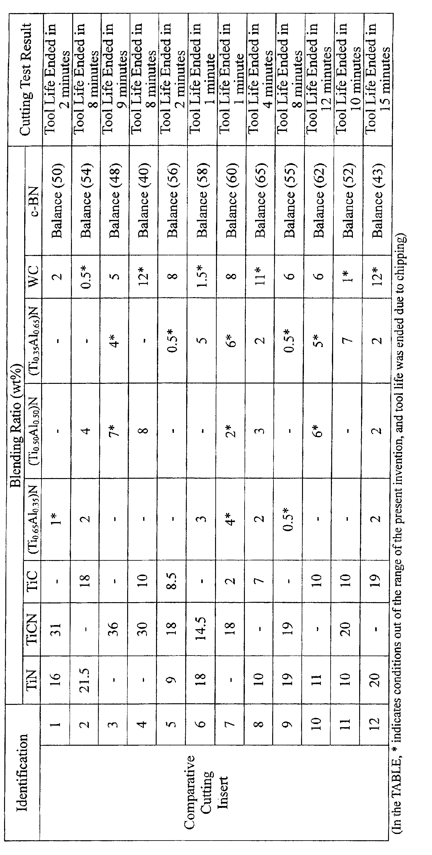
- Ingredient powders i.e., powders of TiN, TiCN, and TiC, for forming a continuously bonded phase, powder of WC, and powder of (Ti, Al)N (i.e., powder of (Ti 0.65 Al 0.35 )N, powder of (Ti 0.50 Al 0.50 )N, and powder of (Ti 0.35 Al 0.65 )N, for forming an intermediate adhesion phase, and powder of c-BN as a hard dispersed phase, all of which have a predetermined average grain size in a range from 0.5 to 2 ⁇ m, were prepared and mixed in accordance with blending ratios shown in TABLES 1 and 2.
- the ingredient powders were mixed under wet conditions using a ball mill for 72 hours, were dried, and were compacted under pressure of 100 MPa so as to form a green compact having a diameter of 50 mm and a thickness of 1.5 mm.
- the green compact was held in a vacuum (pressure of 1Pa) at a predetermined temperature in a range from 900 to 1300°C for 1 hour so as to be pre-sintered.
- the pre-sintered compact was superposed on a cemented carbide plate which was separately prepared and had a diameter of 50 mm and a thickness of 2 mm (composition: WC-8%Co), and then the pre-sintered compact with the cemented carbide plate was inserted into an ultra-high pressure sintering apparatus held under a pressure of 5 GPa at a predetermined temperature in a range from 1200 to 1400°C for 30 minutes so as to be sintered.
- the blending ratio of one of the powder of (Ti, Al) N and the powder of WC, for forming the intermediate adhesion phase was set out of the range determined according to the present invention.
- the cutting inserts were subjected to ultrasonic cleaning in an acetone solvent, were dried, and set in an ordinary arc ion plating apparatus.
- the arc ion plating apparatus titanium metal was set as a cathode electrode (vapor source), air was discharged so that the inside of the apparatus was maintained at a vacuum at a pressure of 0.5 Pa or less, and the inside of the apparatus was heated to a temperature of 500°C using a heater.
- a bias DC voltage of -1000 V was applied to the cutting insert, and an electric current of 100A was made flow as an arc discharge between the cathode electrode, i.e., titanium metal, and an anode electrode, so that the surface of the cutting insert was subjected to Ti bombardment cleaning.
- a nitrogen gas as a reaction gas, was introduced into the apparatus so as to prepare a reaction atmosphere at a pressure of 5Pa, a bias DC voltage of-100 V was applied to the cutting insert, and an electric current of 100A was made to flow as an arc discharge between the cathode electrode and the anode electrode, so that a gold colored TiN layer having an average thickness of 1.5 ⁇ m was vapor-deposited on the surface of the cutting insert 11 of the present invention and the surface of the comparative cutting insert 11.
- Each of the cutting inserts was brazed to a stepped portion formed in a tip of a cutting edge of a cemented carbide body (composition: WC-10%Co) so as to form a throwaway type cutting tool having a shape defined in the JIS (Japanese Industrial Standard)-TNMA160408.
- Each cutting insert was subjected to a high-speed, dry, continuous surface finish cutting test in which a workpiece of difficult-to-machine material was machined, and, in each case, flank wear of the cutting edge was measured.
- the cutting inserts 1 to 12 of the present invention did not have chipping in the cutting edge thereof, i.e., exhibited excellent wear resistance and excellent long-term cutting performance, even when being used for high-speed turning operations or high-speed surface finishing operations for workpieces of difficult-to-machine material such as carburized steel.
- the blending ratio of at least one of the powder of Ti-Al compound and the powder of WC, for forming the intermediate adhesion phase was set out of the range determined according to the present invention, as in the cases of the comparative cutting inserts 1 to 12, the cutting edge had chipping therein, and thereby tool life was exhausted in a relatively short period.
- the c-BN based cutting insert of the present invention exhibits excellent chipping resistance, of course, in cutting operations under normal conditions, and even in high-seed cutting operations or high-speed surface finishing operations for workpieces of difficult-to-machine material such as high-hardened steel because the c-BN phase is firmly bonded to the TiCN phase for substantially forming the continuously bonded phase due to the inter mediate adhesion phase intervening therebetween; therefore, the c-BN based cutting insert of the present invention sufficiently meets the requirements that cutting apparatuses should have high performance and high power, and that cutting operations should be performed with less power and less energy.
- Ingredient powders i.e., powders of TiN and TiCN, for forming a continuously bonded phase, powder of Ti-Al compound, powder of Ti 2 AlN, and powder of WC, for forming an intermediate adhesion phase, and powder of c-BN as a hard dispersed phase, all of which have a predetermined average grain size in a range from 0.5 to 4 ⁇ m, were prepared and mixed in accordance with blending ratios shown in TABLE 3.
- the ingredient powders were mixed under wet conditions using a ball mill for 72 hours, were dried, and were compacted under pressure of 100 MPa so as to form a green compact having a diameter of 50 mm and a thickness of 1.5 mm.
- the green compact was held in a vacuum at a predetermined temperature in a range from 900 to 1300°C for 1 hour so as to be pre-sintered.
- the pre-sintered compact was superposed on a cemented carbide plate which was separately prepared and had a diameter of 50 mm and a thickness of 2 mm (composition: WC-8%Co), and then the pre-sintered compact with the cemented carbide plate was inserted into an ultra-high pressure sintering apparatus and held under pressure of 5 GPa at predetermined temperature in a range from 1200 to 1400°C for 30 minutes so as to be sintered.
- the blending ratio of one of the powder of Ti-Al compound, the powder of Ti 2 AlN, and the powder of WC, for forming the intermediate adhesion phase was set out of the range determined according to the present invention.
- the cutting inserts were subjected to ultrasonic cleaning in an acetone solvent, were dried, and were set in an ordinary arc ion plating apparatus.
- titanium metal was set as a cathode electrode (vapor source), air was evacuated so that the inside of the apparatus was maintained at a vacuum at a pressure of 0.5 Pa or less, and the inside of the apparatus was heated to a temperature of 500°C using a heater.
- a bias DC voltage of -1000 V was applied to the cutting insert, and an electrical current of 100A was made flow as an arc discharge between the cathode electrode, i.e., titanium metal, and an anode electrode, so that the surface of the cutting insert was subjected to Ti bombardment cleaning.
- a nitrogen gas as a reaction gas, was introduced into the apparatus so as to prepare a reaction atmosphere at a pressure of 5Pa, a bias DC voltage of -100 V was applied to the cutting insert, and an electric current of 100A was made flow as an arc discharge between the cathode electrode and the anode electrode, so that a gold colored TiN layer having an average thickness of 1.5 ⁇ m was vapor-deposited on each of the surface of the cutting insert 8 of the present invention and the surface of the comparative cutting insert 6.
- Each of the cutting inserts was brazed to a stepped portion formed in a tip of a cutting edge of a cemented carbide body (composition: WC-10%Co) so as to form a throwaway type cutting tool having a shape defined in the JIS-TNMA160408.
- Each cutting insert was subjected to a high-speed, dry, continuous surface finish cutting test in which a workpiece of difficult-to-machine material was machined, and, in each case, flank wear of the cutting edge was measured.
- the cutting inserts 1 to 8 of the present invention did not have chipping in the cutting edge thereof, i.e., exhibited excellent wear resistance and excellent long-term cutting performance, even when being used for high-speed turning operations or high-speed surface finishing operations for workpieces of difficult-to-machine material such as carburized steel.
- the blending ratio of at least one of the powder of Ti-Al compound, the powder of Ti 2 AlN, and the powder of WC, for forming the intermediate adhesion phase was set out of the range determined according to the present invention, as in the cases of the comparative cutting inserts 1 to 6, the cutting edge had chipping therein, and thereby tool life was exhausted in a relatively short period.
- TABLE 3 further shows flank wear of the cutting edge as a result of high-speed, dry, continuous surface finish cutting tests in which workpieces of difficult-to-machine material were machined using cutting insert 9 in which a portion of TiN and TiCN for forming the continuously bonded phase was substituted by TaC (tantalum carbide), and cutting insert 10 in which, similarly, a portion of TiN and TiCN was substituted by NbC, as further Examples.
- These cutting inserts 9 and 10 did not have chipping in the cutting edge thereof, i.e., exhibited excellent wear resistance, as in the cases of cutting inserts 1 to 8, even when being used for high-speed surface finishing operations for workpieces of difficult-to-machine material such as carburized steel.
- the c-BN based cutting insert of the present invention exhibits excellent chipping resistance, of course, in cutting operations under normal conditions, and even in high-speed cutting operations or high-speed surface finishing operations for workpieces of difficult-to-machine material such as high-hardened steel.
- the c-BN phase is firmly bonded to the TiN phase and the TiCN phase, for substantially forming the continuously bonded phase, due to the intermediate adhesion phase intervening therebetween; therefore, the c-BN based cutting insert of the present invention sufficiently meets the requirements that cutting apparatuses should have high performance and high power, and that cutting operations should be performed with less power and less energy.
Landscapes
- Chemical & Material Sciences (AREA)
- Engineering & Computer Science (AREA)
- Ceramic Engineering (AREA)
- Materials Engineering (AREA)
- Organic Chemistry (AREA)
- Structural Engineering (AREA)
- Manufacturing & Machinery (AREA)
- Inorganic Chemistry (AREA)
- Mechanical Engineering (AREA)
- Crystallography & Structural Chemistry (AREA)
- Metallurgy (AREA)
- Ceramic Products (AREA)
- Cutting Tools, Boring Holders, And Turrets (AREA)
- Powder Metallurgy (AREA)
Abstract
Description


Claims (6)
- A cutting insert including cubic boron nitride based ultra-high pressure sintered material exhibiting, in a structural observation using an electron microscope, a substantial three-phase structure including a continuously bonded phase, a hard dispersed phase, and an intermediate adhesion phase intervening between the continuously bonded phase and the hard dispersed phase, the cubic boron nitride based ultra-high pressure sintered material comprising:titanium compound for forming the continuously bonded phase;at least a nitride compound having titanium and aluminum, and tungsten carbide, for forming the intermediate adhesion phase; andcubic boron nitride for forming the hard dispersed phase.
- A cutting insert according to claim 1, wherein the cubic boron nitride based ultra-high pressure sintered material consisting of:15 to 56 wt% of at least two components selected from titanium nitride, titanium carbonitride, and titanium carbide, or 15 to 56 wt% titanium carbonitride, for forming the continuously bonded phase;2 to 10 wt% nitride compound having titanium and aluminum and 2 to 10 wt% tungsten carbide, for forming the intermediate adhesion phase; and(35 to 65 wt%) cubic boron nitride, as the balance, for forming the hard dispersed phase.
- A cutting insert according to claim 1, wherein the cubic boron nitride based ultra-high pressure sintered material consisting of:20 to 37 wt% titanium nitride and/or titanium carbonitride, for forming the continuously bonded phase;3 to 8 wt% inter-metallic compound having titanium and aluminum, 5 to 10 wt% nitride compound having titanium and aluminum, and 5 to 15 wt% tungsten carbide, for forming the intermediate adhesion phase; and(35 to 55 wt%) cubic boron nitride, as the balance, for forming the hard dispersed phase.
- A cutting insert according to claim 1, wherein the cubic boron nitride based ultra-high pressure sintered material consisting of:10 to 32 wt% titanium nitride and/or titanium carbonitride, and 5 to 10 wt% tantalum carbide, for forming the continuously bonded phase;3 to 8 wt% inter-metallic compound having titanium and aluminum, 5 to 10 wt% nitride compound having titanium and aluminum, and 5 to 15 wt% tungsten carbide, for forming the intermediate adhesion phase; and(35 to 55 wt%) cubic boron nitride, as the balance, for forming the hard dispersed phase.
- A cutting insert according to claim 1, wherein the cubic boron nitride based ultra-high pressure sintered material consisting of:10 to 32 wt% titanium nitride and/or titanium carbonitride, and 5 to 10 wt% niobium carbide, for forming the continuously bonded phase;3 to 8 wt% inter-metallic compound having titanium and aluminum, 5 to 10 wt% nitride compound having titanium and aluminum, and 5 to 15 wt% tungsten carbide, for forming the intermediate adhesion phase; and(35 to 55 wt%) cubic boron nitride, as the balance, for forming the hard dispersed phase.
- A cutting insert according to claim 1, comprising, on the surface thereof, a titanium nitride layer having average film thickness of 0.5 to 5 µm as a use-of-insert indication layer.
Applications Claiming Priority (5)
| Application Number | Priority Date | Filing Date | Title |
|---|---|---|---|
| JP2002117578 | 2002-04-19 | ||
| JP2002117580 | 2002-04-19 | ||
| JP2002117580A JP2003145319A (en) | 2001-08-29 | 2002-04-19 | Cutting tip made of cubic boron nitride based ultra-high pressure sintered material with excellent chipping resistance |
| JP2002117578A JP2003176177A (en) | 2001-10-04 | 2002-04-19 | Cutting tip made of cubic boron nitride based ultra-high pressure sintered material with excellent chipping resistance |
| PCT/JP2003/002362 WO2003089172A1 (en) | 2002-04-19 | 2003-02-28 | Cubic boron nitride base ultra-high pressure sintered material cutting tip |
Publications (3)
| Publication Number | Publication Date |
|---|---|
| EP1498199A1 true EP1498199A1 (en) | 2005-01-19 |
| EP1498199A4 EP1498199A4 (en) | 2007-05-02 |
| EP1498199B1 EP1498199B1 (en) | 2010-08-18 |
Family
ID=29253601
Family Applications (1)
| Application Number | Title | Priority Date | Filing Date |
|---|---|---|---|
| EP03746884A Expired - Lifetime EP1498199B1 (en) | 2002-04-19 | 2003-02-28 | Cubic boron nitride base ultra-high pressure sintered material cutting tip |
Country Status (6)
| Country | Link |
|---|---|
| US (1) | US7112235B2 (en) |
| EP (1) | EP1498199B1 (en) |
| KR (2) | KR101121412B1 (en) |
| CN (1) | CN1662334B (en) |
| DE (1) | DE60333829D1 (en) |
| WO (1) | WO2003089172A1 (en) |
Cited By (4)
| Publication number | Priority date | Publication date | Assignee | Title |
|---|---|---|---|---|
| WO2006046753A1 (en) * | 2004-10-28 | 2006-05-04 | Kyocera Corporation | Cubic boron nitride sintered material and cutting tool using the same |
| US7670980B2 (en) | 2005-10-28 | 2010-03-02 | Sandvik Intellectual Property Ab | Cubic boron nitride cutting tool insert with excellent resistance to chipping and edge fracture |
| US8507082B2 (en) | 2011-03-25 | 2013-08-13 | Kennametal Inc. | CVD coated polycrystalline c-BN cutting tools |
| US9028953B2 (en) | 2013-01-11 | 2015-05-12 | Kennametal Inc. | CVD coated polycrystalline c-BN cutting tools |
Families Citing this family (10)
| Publication number | Priority date | Publication date | Assignee | Title |
|---|---|---|---|---|
| SE530944C2 (en) * | 2007-04-27 | 2008-10-28 | Sandvik Intellectual Property | Notch |
| CN101892412B (en) * | 2010-06-23 | 2012-05-23 | 郑州博特硬质材料有限公司 | A kind of cubic boron nitride/titanium carbide composite sintered cutting tool material and its preparation method |
| JP5892423B2 (en) * | 2012-03-08 | 2016-03-23 | 三菱マテリアル株式会社 | CBN sintered compact cutting tool with excellent toughness |
| EP2855053B1 (en) * | 2012-05-31 | 2018-10-31 | Sandvik Intellectual Property AB | Method of making a cbn material |
| CN103011832B (en) * | 2012-12-03 | 2016-08-17 | 合肥杰事杰新材料股份有限公司 | A kind of cubic boron nitride material pliers and preparation method thereof |
| JP6343888B2 (en) * | 2013-08-27 | 2018-06-20 | 三菱マテリアル株式会社 | Cubic boron nitride sintered body cutting tool with excellent fracture resistance |
| JP2017080878A (en) * | 2015-10-28 | 2017-05-18 | 三菱マテリアル株式会社 | Surface coated cutting tool |
| CN105753466A (en) * | 2016-03-07 | 2016-07-13 | 四川大学 | Synthesis method of polycrystal jade under high pressure |
| WO2021181518A1 (en) * | 2020-03-10 | 2021-09-16 | 住友電工ハードメタル株式会社 | Reamer |
| WO2025224238A1 (en) * | 2024-04-26 | 2025-10-30 | Ab Sandvik Coromant | A coated cutting tool |
Family Cites Families (21)
| Publication number | Priority date | Publication date | Assignee | Title |
|---|---|---|---|---|
| AU512633B2 (en) * | 1976-12-21 | 1980-10-23 | Sumitomo Electric Industries, Ltd. | Sintered tool |
| JPS569279A (en) * | 1979-06-28 | 1981-01-30 | Sumitomo Electric Industries | Sintered body for cutting tool and its manufacture |
| JPS56156738A (en) | 1981-03-16 | 1981-12-03 | Sumitomo Electric Ind Ltd | Sintered body for high hardness tool and its manufacture |
| JPS602378B2 (en) * | 1981-12-25 | 1985-01-21 | 三菱マテリアル株式会社 | Cubic boron nitride-based ultra-high pressure sintered material for cutting tools |
| JPS605666B2 (en) * | 1982-03-23 | 1985-02-13 | 三菱マテリアル株式会社 | Ultra-high pressure sintered material for cutting tools |
| JPS607022B2 (en) * | 1982-08-31 | 1985-02-21 | 三菱マテリアル株式会社 | Cubic boron nitride-based ultra-high pressure sintered material for cutting tools |
| US4647546A (en) * | 1984-10-30 | 1987-03-03 | Megadiamond Industries, Inc. | Polycrystalline cubic boron nitride compact |
| JPS61201751A (en) * | 1985-03-04 | 1986-09-06 | Nippon Oil & Fats Co Ltd | High hardness sintered body and its manufacture |
| JPH0713279B2 (en) * | 1990-01-12 | 1995-02-15 | 日本油脂株式会社 | High-pressure phase boron nitride sintered body for cutting tool and manufacturing method thereof |
| JP3035797B2 (en) * | 1991-07-04 | 2000-04-24 | 三菱マテリアル株式会社 | Cutting insert made of cubic boron nitride based ultra-high pressure sintered material with high strength |
| JP3146747B2 (en) * | 1993-04-01 | 2001-03-19 | 三菱マテリアル株式会社 | Cutting tools made of cubic boron nitride based ultra-high pressure sintered material with excellent wear and fracture resistance |
| US5639285A (en) * | 1995-05-15 | 1997-06-17 | Smith International, Inc. | Polycrystallline cubic boron nitride cutting tool |
| JPH10114575A (en) * | 1996-10-04 | 1998-05-06 | Sumitomo Electric Ind Ltd | High hardness sintered body for tools |
| EP0879806B1 (en) * | 1996-12-03 | 2004-10-13 | Sumitomo Electric Industries, Ltd. | High-pressure phase boron nitride base sinter |
| JPH10182234A (en) * | 1996-12-25 | 1998-07-07 | Agency Of Ind Science & Technol | Cubic boron nitride based sintered material and method for producing the same |
| RU2220929C2 (en) * | 1998-07-22 | 2004-01-10 | Сумитомо Электрик Индастриз, Лтд. | Sintered blanc from boron nitride with cubic lattice (options) |
| US6265337B1 (en) * | 1998-12-04 | 2001-07-24 | Sumitomo Electric Industries, Ltd. | High strength sintered body |
| US6140262A (en) * | 1999-07-27 | 2000-10-31 | Smith International, Inc. | Polycrystalline cubic boron nitride cutting tool |
| JP2001322006A (en) * | 2000-05-12 | 2001-11-20 | Mitsubishi Materials Corp | Surface-coated cemented carbide cutting tool with excellent wear resistance |
| JP3637882B2 (en) * | 2000-08-31 | 2005-04-13 | 住友電気工業株式会社 | Surface coated boron nitride sintered body tool |
| US6814775B2 (en) * | 2002-06-26 | 2004-11-09 | Diamond Innovations, Inc. | Sintered compact for use in machining chemically reactive materials |
-
2003
- 2003-02-28 EP EP03746884A patent/EP1498199B1/en not_active Expired - Lifetime
- 2003-02-28 KR KR1020097017127A patent/KR101121412B1/en not_active Expired - Lifetime
- 2003-02-28 US US10/510,239 patent/US7112235B2/en not_active Expired - Lifetime
- 2003-02-28 CN CN038143224A patent/CN1662334B/en not_active Expired - Lifetime
- 2003-02-28 WO PCT/JP2003/002362 patent/WO2003089172A1/en not_active Ceased
- 2003-02-28 KR KR10-2004-7016416A patent/KR20040101476A/en not_active Ceased
- 2003-02-28 DE DE60333829T patent/DE60333829D1/en not_active Expired - Lifetime
Cited By (5)
| Publication number | Priority date | Publication date | Assignee | Title |
|---|---|---|---|---|
| WO2006046753A1 (en) * | 2004-10-28 | 2006-05-04 | Kyocera Corporation | Cubic boron nitride sintered material and cutting tool using the same |
| US7902098B2 (en) | 2004-10-28 | 2011-03-08 | Kyocera Corporation | Cubic boron nitride sintered material and cutting tool using the same |
| US7670980B2 (en) | 2005-10-28 | 2010-03-02 | Sandvik Intellectual Property Ab | Cubic boron nitride cutting tool insert with excellent resistance to chipping and edge fracture |
| US8507082B2 (en) | 2011-03-25 | 2013-08-13 | Kennametal Inc. | CVD coated polycrystalline c-BN cutting tools |
| US9028953B2 (en) | 2013-01-11 | 2015-05-12 | Kennametal Inc. | CVD coated polycrystalline c-BN cutting tools |
Also Published As
| Publication number | Publication date |
|---|---|
| KR20090101383A (en) | 2009-09-25 |
| EP1498199B1 (en) | 2010-08-18 |
| KR20040101476A (en) | 2004-12-02 |
| US7112235B2 (en) | 2006-09-26 |
| WO2003089172A1 (en) | 2003-10-30 |
| DE60333829D1 (en) | 2010-09-30 |
| KR101121412B1 (en) | 2012-03-22 |
| CN1662334B (en) | 2010-09-01 |
| US20050145066A1 (en) | 2005-07-07 |
| EP1498199A4 (en) | 2007-05-02 |
| CN1662334A (en) | 2005-08-31 |
Similar Documents
| Publication | Publication Date | Title |
|---|---|---|
| EP1867754B1 (en) | Cutting tool made of surface-coated cubic boron nitride-based ultra-high-pressure sintered material | |
| EP1470879A1 (en) | Surface coated cutting tool member having hard coating layer exhibiting excellent abrasion resistance in high-speed cutting, and method for forming said hard coating layer on surface of cutting tool | |
| EP1801260B1 (en) | Cutting tool made of surface-coated cubic boron nitride-based ultrahigh pressure sintered material | |
| US7112235B2 (en) | Cubic boron nitride base ultra-high pressure sintered material cutting tip | |
| EP1535680A1 (en) | Coated cutting tool member | |
| JP2008254159A (en) | Cutting tool made of surface coated cubic boron nitride based ultra high pressure sintered material | |
| JP4883475B2 (en) | Cutting tool made of surface-coated cubic boron nitride-based ultra-high pressure sintered material that exhibits excellent wear resistance in high-speed cutting of hardened steel | |
| JP2008302439A (en) | Cutting tool made of surface coated cubic boron nitride based ultra high pressure sintered material | |
| JP2003236710A (en) | Cutting tip made of cubic boron nitride based ultra-high pressure sintered material with excellent chipping resistance | |
| JP4807575B2 (en) | Cutting tool made of surface-coated cubic boron nitride-based ultra-high pressure sintered material that exhibits excellent wear resistance in high-speed cutting of hardened steel | |
| JP3849135B2 (en) | Cutting tool made of surface-coated cemented carbide with a hard coating layer showing good biting properties against the work material under heavy cutting conditions | |
| JP4883473B2 (en) | Cutting tool made of surface-coated cubic boron nitride-based ultra-high pressure sintered material that exhibits excellent chipping resistance in hard cutting of hardened steel | |
| JP2003236707A (en) | Cutting tip made of cubic boron nitride based ultra-high pressure sintered material with excellent chipping resistance | |
| JP4883471B2 (en) | Cutting tool made of surface-coated cubic boron nitride-based ultra-high pressure sintered material that exhibits excellent chipping resistance in hard cutting of hardened steel | |
| JP4883472B2 (en) | Cutting tool made of surface-coated cubic boron nitride-based ultra-high pressure sintered material that exhibits excellent chipping resistance in hard cutting of hardened steel | |
| JP2001162411A (en) | Surface-coated cemented carbide cutting tool with excellent wear and chipping resistance | |
| JP2003175407A (en) | Cutting tip made of cubic boron nitride based ultra-high pressure sintered material with excellent chipping resistance | |
| JP2008302438A (en) | Cutting tool made of surface coated cubic boron nitride based ultra high pressure sintered material | |
| JP4748446B2 (en) | Cutting tool made of surface-coated cubic boron nitride-based ultra-high pressure sintered material that exhibits excellent chipping resistance when cutting hard difficult-to-cut materials | |
| JP4416960B2 (en) | Slow-away cutting tip made of surface-coated cemented carbide that provides excellent wear resistance in high-speed cutting | |
| JP4883474B2 (en) | Cutting tool made of surface-coated cubic boron nitride-based ultra-high pressure sintered material that exhibits excellent wear resistance in high-speed cutting of hardened steel | |
| JP4748447B2 (en) | Cutting tool made of surface-coated cubic boron nitride-based ultra-high pressure sintered material that exhibits excellent chipping resistance in high-speed cutting of hard difficult-to-cut materials | |
| JP3982348B2 (en) | Surface coated cemented carbide cutting tool with excellent wear resistance with hard coating layer in high speed cutting | |
| JP2003236708A (en) | Cutting tip made of cubic boron nitride based ultra-high pressure sintered material with excellent chipping resistance | |
| JP2003145319A (en) | Cutting tip made of cubic boron nitride based ultra-high pressure sintered material with excellent chipping resistance |
Legal Events
| Date | Code | Title | Description |
|---|---|---|---|
| PUAI | Public reference made under article 153(3) epc to a published international application that has entered the european phase |
Free format text: ORIGINAL CODE: 0009012 |
|
| 17P | Request for examination filed |
Effective date: 20041015 |
|
| AK | Designated contracting states |
Kind code of ref document: A1 Designated state(s): AT BE BG CH CY CZ DE DK EE ES FI FR GB GR HU IE IT LI LU MC NL PT SE SI SK TR |
|
| A4 | Supplementary search report drawn up and despatched |
Effective date: 20070403 |
|
| RIC1 | Information provided on ipc code assigned before grant |
Ipc: C22C 26/00 20060101ALI20070328BHEP Ipc: C04B 35/5831 20060101AFI20070328BHEP |
|
| 17Q | First examination report despatched |
Effective date: 20080409 |
|
| GRAP | Despatch of communication of intention to grant a patent |
Free format text: ORIGINAL CODE: EPIDOSNIGR1 |
|
| GRAS | Grant fee paid |
Free format text: ORIGINAL CODE: EPIDOSNIGR3 |
|
| GRAA | (expected) grant |
Free format text: ORIGINAL CODE: 0009210 |
|
| AK | Designated contracting states |
Kind code of ref document: B1 Designated state(s): DE FR GB IT |
|
| REG | Reference to a national code |
Ref country code: GB Ref legal event code: FG4D |
|
| REF | Corresponds to: |
Ref document number: 60333829 Country of ref document: DE Date of ref document: 20100930 Kind code of ref document: P |
|
| PLBE | No opposition filed within time limit |
Free format text: ORIGINAL CODE: 0009261 |
|
| STAA | Information on the status of an ep patent application or granted ep patent |
Free format text: STATUS: NO OPPOSITION FILED WITHIN TIME LIMIT |
|
| 26N | No opposition filed |
Effective date: 20110519 |
|
| REG | Reference to a national code |
Ref country code: DE Ref legal event code: R097 Ref document number: 60333829 Country of ref document: DE Effective date: 20110519 |
|
| REG | Reference to a national code |
Ref country code: FR Ref legal event code: PLFP Year of fee payment: 14 |
|
| REG | Reference to a national code |
Ref country code: FR Ref legal event code: PLFP Year of fee payment: 15 |
|
| REG | Reference to a national code |
Ref country code: FR Ref legal event code: PLFP Year of fee payment: 16 |
|
| PGFP | Annual fee paid to national office [announced via postgrant information from national office to epo] |
Ref country code: GB Payment date: 20220223 Year of fee payment: 20 Ref country code: DE Payment date: 20220217 Year of fee payment: 20 |
|
| PGFP | Annual fee paid to national office [announced via postgrant information from national office to epo] |
Ref country code: IT Payment date: 20220218 Year of fee payment: 20 Ref country code: FR Payment date: 20220216 Year of fee payment: 20 |
|
| REG | Reference to a national code |
Ref country code: DE Ref legal event code: R071 Ref document number: 60333829 Country of ref document: DE |
|
| REG | Reference to a national code |
Ref country code: GB Ref legal event code: PE20 Expiry date: 20230227 |
|
| PG25 | Lapsed in a contracting state [announced via postgrant information from national office to epo] |
Ref country code: GB Free format text: LAPSE BECAUSE OF EXPIRATION OF PROTECTION Effective date: 20230227 |