EP1497153B1 - Artikelbefestigungssystem - Google Patents
Artikelbefestigungssystem Download PDFInfo
- Publication number
- EP1497153B1 EP1497153B1 EP02723931A EP02723931A EP1497153B1 EP 1497153 B1 EP1497153 B1 EP 1497153B1 EP 02723931 A EP02723931 A EP 02723931A EP 02723931 A EP02723931 A EP 02723931A EP 1497153 B1 EP1497153 B1 EP 1497153B1
- Authority
- EP
- European Patent Office
- Prior art keywords
- article
- rail member
- attachment system
- vehicle
- bracket
- Prior art date
- Legal status (The legal status is an assumption and is not a legal conclusion. Google has not performed a legal analysis and makes no representation as to the accuracy of the status listed.)
- Expired - Lifetime
Links
- 230000033001 locomotion Effects 0.000 claims description 27
- 239000004020 conductor Substances 0.000 claims description 17
- 238000003860 storage Methods 0.000 claims description 15
- 239000000463 material Substances 0.000 claims description 13
- 238000000034 method Methods 0.000 claims description 13
- 230000008878 coupling Effects 0.000 claims description 8
- 238000010168 coupling process Methods 0.000 claims description 8
- 238000005859 coupling reaction Methods 0.000 claims description 8
- 230000005611 electricity Effects 0.000 claims description 6
- 230000003993 interaction Effects 0.000 claims 1
- 239000000356 contaminant Substances 0.000 description 4
- 239000004033 plastic Substances 0.000 description 4
- 229910052782 aluminium Inorganic materials 0.000 description 3
- XAGFODPZIPBFFR-UHFFFAOYSA-N aluminium Chemical compound [Al] XAGFODPZIPBFFR-UHFFFAOYSA-N 0.000 description 3
- 238000010276 construction Methods 0.000 description 3
- 238000009434 installation Methods 0.000 description 3
- 230000008569 process Effects 0.000 description 3
- 230000001413 cellular effect Effects 0.000 description 2
- 235000019504 cigarettes Nutrition 0.000 description 2
- 238000001125 extrusion Methods 0.000 description 2
- 238000004519 manufacturing process Methods 0.000 description 2
- 230000013011 mating Effects 0.000 description 2
- 230000007246 mechanism Effects 0.000 description 2
- 238000012986 modification Methods 0.000 description 2
- 230000004048 modification Effects 0.000 description 2
- RYGMFSIKBFXOCR-UHFFFAOYSA-N Copper Chemical compound [Cu] RYGMFSIKBFXOCR-UHFFFAOYSA-N 0.000 description 1
- FYYHWMGAXLPEAU-UHFFFAOYSA-N Magnesium Chemical compound [Mg] FYYHWMGAXLPEAU-UHFFFAOYSA-N 0.000 description 1
- 229910000831 Steel Inorganic materials 0.000 description 1
- 229920006362 Teflon® Polymers 0.000 description 1
- 239000000853 adhesive Substances 0.000 description 1
- 230000001070 adhesive effect Effects 0.000 description 1
- 238000004378 air conditioning Methods 0.000 description 1
- 235000013361 beverage Nutrition 0.000 description 1
- 230000003749 cleanliness Effects 0.000 description 1
- 239000011248 coating agent Substances 0.000 description 1
- 238000000576 coating method Methods 0.000 description 1
- 238000005097 cold rolling Methods 0.000 description 1
- 239000002131 composite material Substances 0.000 description 1
- 230000006835 compression Effects 0.000 description 1
- 238000007906 compression Methods 0.000 description 1
- 229910052802 copper Inorganic materials 0.000 description 1
- 239000010949 copper Substances 0.000 description 1
- 230000009977 dual effect Effects 0.000 description 1
- 239000012777 electrically insulating material Substances 0.000 description 1
- 238000005286 illumination Methods 0.000 description 1
- 238000005470 impregnation Methods 0.000 description 1
- 238000003780 insertion Methods 0.000 description 1
- 230000037431 insertion Effects 0.000 description 1
- 229910052749 magnesium Inorganic materials 0.000 description 1
- 239000011777 magnesium Substances 0.000 description 1
- 229910052751 metal Inorganic materials 0.000 description 1
- 239000002184 metal Substances 0.000 description 1
- 229910001092 metal group alloy Inorganic materials 0.000 description 1
- 239000000203 mixture Substances 0.000 description 1
- 239000002991 molded plastic Substances 0.000 description 1
- 238000000465 moulding Methods 0.000 description 1
- -1 overlay Substances 0.000 description 1
- 239000004417 polycarbonate Substances 0.000 description 1
- 229920000515 polycarbonate Polymers 0.000 description 1
- 229920001296 polysiloxane Polymers 0.000 description 1
- 239000011347 resin Substances 0.000 description 1
- 229920005989 resin Polymers 0.000 description 1
- 238000000926 separation method Methods 0.000 description 1
- 239000003381 stabilizer Substances 0.000 description 1
- 239000010959 steel Substances 0.000 description 1
- 238000009423 ventilation Methods 0.000 description 1
Images



Classifications
-
- B—PERFORMING OPERATIONS; TRANSPORTING
- B60—VEHICLES IN GENERAL
- B60N—SEATS SPECIALLY ADAPTED FOR VEHICLES; VEHICLE PASSENGER ACCOMMODATION NOT OTHERWISE PROVIDED FOR
- B60N2/00—Seats specially adapted for vehicles; Arrangement or mounting of seats in vehicles
- B60N2/02—Seats specially adapted for vehicles; Arrangement or mounting of seats in vehicles the seat or part thereof being movable, e.g. adjustable
- B60N2/04—Seats specially adapted for vehicles; Arrangement or mounting of seats in vehicles the seat or part thereof being movable, e.g. adjustable the whole seat being movable
- B60N2/06—Seats specially adapted for vehicles; Arrangement or mounting of seats in vehicles the seat or part thereof being movable, e.g. adjustable the whole seat being movable slidable
- B60N2/07—Slide construction
- B60N2/0702—Slide construction characterised by its cross-section
- B60N2/071—T-shaped
-
- B—PERFORMING OPERATIONS; TRANSPORTING
- B60—VEHICLES IN GENERAL
- B60N—SEATS SPECIALLY ADAPTED FOR VEHICLES; VEHICLE PASSENGER ACCOMMODATION NOT OTHERWISE PROVIDED FOR
- B60N2/00—Seats specially adapted for vehicles; Arrangement or mounting of seats in vehicles
- B60N2/02—Seats specially adapted for vehicles; Arrangement or mounting of seats in vehicles the seat or part thereof being movable, e.g. adjustable
- B60N2/04—Seats specially adapted for vehicles; Arrangement or mounting of seats in vehicles the seat or part thereof being movable, e.g. adjustable the whole seat being movable
- B60N2/06—Seats specially adapted for vehicles; Arrangement or mounting of seats in vehicles the seat or part thereof being movable, e.g. adjustable the whole seat being movable slidable
- B60N2/07—Slide construction
- B60N2/0702—Slide construction characterised by its cross-section
- B60N2/0715—C or U-shaped
-
- B—PERFORMING OPERATIONS; TRANSPORTING
- B60—VEHICLES IN GENERAL
- B60N—SEATS SPECIALLY ADAPTED FOR VEHICLES; VEHICLE PASSENGER ACCOMMODATION NOT OTHERWISE PROVIDED FOR
- B60N2/00—Seats specially adapted for vehicles; Arrangement or mounting of seats in vehicles
- B60N2/02—Seats specially adapted for vehicles; Arrangement or mounting of seats in vehicles the seat or part thereof being movable, e.g. adjustable
- B60N2/04—Seats specially adapted for vehicles; Arrangement or mounting of seats in vehicles the seat or part thereof being movable, e.g. adjustable the whole seat being movable
- B60N2/06—Seats specially adapted for vehicles; Arrangement or mounting of seats in vehicles the seat or part thereof being movable, e.g. adjustable the whole seat being movable slidable
- B60N2/07—Slide construction
- B60N2/0722—Constructive details
- B60N2/0725—Closing members for covering the slide
-
- B—PERFORMING OPERATIONS; TRANSPORTING
- B60—VEHICLES IN GENERAL
- B60N—SEATS SPECIALLY ADAPTED FOR VEHICLES; VEHICLE PASSENGER ACCOMMODATION NOT OTHERWISE PROVIDED FOR
- B60N2/00—Seats specially adapted for vehicles; Arrangement or mounting of seats in vehicles
- B60N2/75—Arm-rests
- B60N2/763—Arm-rests adjustable
- B60N2/773—Longitudinal adjustment
-
- B—PERFORMING OPERATIONS; TRANSPORTING
- B60—VEHICLES IN GENERAL
- B60N—SEATS SPECIALLY ADAPTED FOR VEHICLES; VEHICLE PASSENGER ACCOMMODATION NOT OTHERWISE PROVIDED FOR
- B60N2/00—Seats specially adapted for vehicles; Arrangement or mounting of seats in vehicles
- B60N2/75—Arm-rests
- B60N2/79—Adaptations for additional use of the arm-rests
- B60N2/793—Adaptations for additional use of the arm-rests for use as storage compartments
-
- B—PERFORMING OPERATIONS; TRANSPORTING
- B60—VEHICLES IN GENERAL
- B60R—VEHICLES, VEHICLE FITTINGS, OR VEHICLE PARTS, NOT OTHERWISE PROVIDED FOR
- B60R7/00—Stowing or holding appliances inside vehicle primarily intended for personal property smaller than suit-cases, e.g. travelling articles, or maps
- B60R7/04—Stowing or holding appliances inside vehicle primarily intended for personal property smaller than suit-cases, e.g. travelling articles, or maps in driver or passenger space, e.g. using racks
-
- B—PERFORMING OPERATIONS; TRANSPORTING
- B62—LAND VEHICLES FOR TRAVELLING OTHERWISE THAN ON RAILS
- B62D—MOTOR VEHICLES; TRAILERS
- B62D27/00—Connections between superstructure or understructure sub-units
- B62D27/06—Connections between superstructure or understructure sub-units readily releasable
Definitions
- the present invention relates to an article attachment system for a motor vehicle.
- the present invention relates more particularly to an article attachment system slideably mounting and removably attaching an article in a motor vehicle.
- consoles The use of systems for mounting articles such as consoles in vehicles has been known for many years.
- the articles or consoles are fixed in a single location and may include instruments, gauges, storage compartments, cup holders, as well as functional devices such as the gear shift lever, the parking brake actuator, side window adjusters, etc.
- lids or covers may be used with consoles to conceal items such as coins, CD's, tapes, and other personal items used by the driver or vehicle occupants. Covers for such compartments are usually pivoted along one edge so that they may be opened to provide access and closed to provide either an armrest or other functionality.
- storage devices may be located in instrument panels, including, for example, cigarette ashtrays, cup or can holders, etc.
- the "Vehicle Seat Assembly” includes a fixed center console between the front seats and a translatable center seat which moves from a rearward position in which it is aligned with the second row seats to a forward position in which it is located more closely to the front seats.
- the center seat includes a child safety seat mounted thereon.
- a console box that can move forwardly and rearwardly is disclosed in U.S. Patent No. 5,951,084 issued to Okozaki et al. on September 14, 1999 for "Seat Structure for a Vehicle.”
- the console forms a portion of a rear seat and includes a cavity and a portion which folds down to form an armrest.
- a carriage including rollers facilitates console movement.
- FIG. 62-194953 Yet another sliding console is shown in Japanese Patent No. 62-194953 .
- This device is similar to some of the aforementioned consoles and allows for the console to slide under the front instrument panel by fixing a guide rail between the cabin front and a position between the seats.
- the gear shift lever is separately slidable along the same rails to allow optimum functioning at the side of the front seat, while maintaining a compact construction when the shift lever and the consoles are stored, one within the other.
- EP 0 117 131 discloses a longitudinal slide mechanism for a vehicle seat that includes first and second elongate members relatively slideable along their longitudinal axes. The cross-sections of the members are such that they cannot be separated in any direction transverse to the longitudinal axes. Means are provided for locking the members against longitudinal movement in any one of a plurality of positions.
- console movement While the general concept of console movement is addressed in the above patent art, generally ignored is the concealment of a positioning mechanism to reduce the introduction of contaminants and other foreign material that may otherwise interfere with the movement of the article, and to conceal pinch-points that may be created by the interface of moving or engaging parts. Also generally ignored is the removability of the console and the ability to interchange the console with other consumer oriented articles useful in connection with a vehicle interior. Also generally ignored is the ability to move the console or article to a position beneath or nested with an instrument panel within the vehicle.
- a positioning system for an article in a manner that minimizes introduction of contaminants and other foreign materials commonly found in vehicle interiors to improve the functionality of the positioning system. It would also be advantageous to provide an article attachment system with a positioning system for placing the article in one of a plurality of incremental positions in a manner that conceals engageable components that may create pinch-points or hazards to a user. It would be further advantageous to provide an article attachment system having a positioning system adapted to self-engage in the event that is misaligned by a user. It would be further advantageous to provide an article attachment system where the article may be removed from the vehicle. It would also be advantageous to provide an article attachment system capable of receiving other consumer-oriented articles useful with a vehicle interior that are adapted to engage the positioning system.
- an article attachment system capable of sliding an article to a position beneath or nested with an instrument panel in a vehicle. It would also be advantageous to provide an article attachment system having an integral lighting system for improved night time illumination. It would also be advantageous to provide an article attachment system with a sensor indicating when the article is not secured within the vehicle.
- the present invention relates to an article attachment system for a vehicle, having an elongated rail member adapted to attach to the vehicle where the rail member defines at least one partially enclosed space having at least one slide interface and a plurality of projections, and a bracket operably engaging the rail and adapted for mounting at least one article, and a positioning device operably engaging the bracket and having at least one extension adapted to move between an engaged position adapted for securing the article to the rail and a released position adapted for moving the article relative to the rail.
- the present invention also relates to an article attachment system for a vehicle interior having an elongated rail member coupled to a floor portion of the vehicle interior where the rail member defines at least one partially concealed channel having a slide interface and a plurality of positioning elements; a bracket adapted to couple to an article, the bracket having at least one non-rotational glide operably engaging the slide interface for longitudinal movement along the rail member; and a positioning device coupled to the bracket for selectively securing the bracket at one of a plurality of locations along the rail member.
- the present invention further relates to a kit for an article attachment system, having a rail member adapted for attachment to the interior portion of a vehicle where the rail defines at least one partially enclosed space having at least one surface adapted for slideable engagement, and a bracket member adapted to couple to an article and adapted to slideably engage the surface, and a positioning device adapted to releasably secure the article in any one of a plurality of locations on the rail member, and an actuator adapted to move the positioning device between an engaged position where movement of the article is prevented and a released position where movement of the console is permitted.
- the present invention also relates to a method of providing an article attachment system for use in a vehicle interior, including the steps of providing a rail member adapted for coupling to the vehicle interior, the rail member defining a partially enclosed space having a surface, and providing a bracket adapted to receive an article and adapted to engage the surface, and coupling a positioning device to the bracket, where the positioning device is adapted for movement between an engaged position where the positioning device engages the rail member and a released position where the positioning device is substantially free of engagement from the rail member, and coupling the article to the rail member.
- the present invention further relates to a system for removably attaching one or more articles in a vehicle interior and includes means for providing an elongated rail member having a partially concealed space, means for coupling the elongated rail member to the vehicle interior, means for mounting an article to the elongated rail member, and means for releasably securing the article in plurality of positions on the elongated rail member.
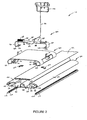
- FIGURE 1 is an exploded perspective view from a rear end of an article attachment system according to a preferred embodiment of the present invention
- FIGURE 2 is a partial exploded perspective view, similar to that of FIGURE 1 , but showing the additional detail of the system according to a preferred embodiment of the present invention.
- FIGURE 3 is an end view from a front end of the article attachment system according to a preferred embodiment of the present invention.
- FIGURE 4 is a perspective view of a portion of a positioning device for an article attachment system according to a preferred embodiment of the present invention.
- FIGURE 5 is a perspective view of a portion of a rail member for an article attachment system according to a preferred embodiment of the present invention.
- Article attachment system 10 includes an elongated base member (e.g. track, runner, guide, etc.) shown schematically as a rail member 20, a movable support interface (e.g. slider, cover, etc.) shown schematically as a bracket 60, adapted to engage rail member 20 in a reciprocatingly slideable relationship and to support in a movable or stationary manner an article 12 (e.g. console, storage device, container, consumer object, etc.) shown schematically as a center console, and a releasable retainer interface (e.g. lock, latch, etc.) shown as a positioning device 80.
- a elongated base member e.g. track, runner, guide, etc.
- a movable support interface e.g. slider, cover, etc.
- bracket 60 adapted to engage rail member 20 in a reciprocatingly slideable relationship and to support in a movable or stationary manner
- an article 12 e.g. console, storage device, container, consumer object, etc.
- Rail member 20, bracket 60, and positioning device 80 cooperate to provide a movable and selectively positionable article attachment system for use in a vehicle.
- article attachment system 10 is shown for use within the interior of a motor vehicle (e.g. automobile, minivan, sport utility vehicle, truck, recreation vehicle, etc.).
- the article attachment system may also be used on an exterior portion of the vehicle, including, but not limited to, a truck bed or cargo storage area.
- the article attachment system may be used internally or externally in any other vehicle applications such as farm or construction equipment, boats, aircraft or in non-vehicular applications such as production facilities, offices, shops, etc.
- Article 12 is coupled to bracket 60 in any suitable conventional manner such as a sliding interference fit, snap-fit connectors, quarter-turn latches, quick-disconnects, spring clips (e.g. Z-axis clips, etc.) or mechanical fasteners (screws, bolts, rivets, etc.).
- article 12 is a center console for a vehicle and may include such items as can or cup holders, storage bins, gear shift and brake components, instruments, lights, lids, push-push container holders, cavities, trays, electrical ports for connection of cellular telephones, computers, ports for connection of infotainment devices, such as DVD players, etc.
- the invention is not to be limited to any particular functionality for the article, the number of articles or any particular relationship between articles if more than one is employed. Two articles can abut one another, but they may, in fact, be arranged to nest, one within the other, etc.
- the bracket may be integrally formed with the article or the bracket may be combined with the positioning device as a single unit.
- Article 12 may be selectively removed from vehicle by disengaging bracket 60 from rail 20 and removing the article, as will be further described.
- the article may be any consumer oriented object or device adapted for use in connection with a vehicle, and configured to receive a bracket, or have an integrally formed bracket, or be configured to be directly received on the rail in a fixed or slideable manner.
- Such alternative articles may include, among others, storage bins or compartments, cargo management devices, carrier racks, office or entertainment devices, holders, brackets, child safety seats, jump seats, storage platforms, tables, camping gear, etc.
- Rail member 20 has an elongated shape adapted for securing to the floor or base of a vehicle.
- rail 20 is laterally (i.e. side to side) centered within the vehicle and extends in a longitudinal (i.e. fore and aft) direction between the front seats (not shown) and may extend between or beneath seats in one or more rows of rear seating (not shown) in the vehicle.
- Rail 20 may any suitable length and location within the vehicle to suit intended applications.
- Rail 20 may extend forward to a position that allows article 12 to be positioned beneath, or nested with, an instrument panel or console (not shown) in a forward location of the vehicle interior. Rail 20 may also extend rearward to an intermediate location within the vehicle, or may extend the full length of the vehicle interior to a rearward position that abuts a rearward vehicle portion such as a end wall, lift gate, or cargo section (not shown). Rail 20 may also include a rear stop or end piece 22 that limits movement of article 12 when it reaches the rear end of rail 20. The rear end piece 22 may be removable or reconfigurable to allow article 12 to be removed from rail 20 by sliding article 12 off of the rear end of rail 20.
- the rear end piece 22 may also be reconfigurable in a manner that serves as a guide for sliding the article onto rail 20.
- the rail 20 may be provided as a single member or may be provided in multiple segments that may be selectively removed or joined for custom-configuring a rail pattern adapted for a specific vehicle or user application, where the rear end piece 22 may be joined to the rearward end of any such rail segments.
- one or more rails may be used and oriented in any suitable direction, or positioned in any suitable location within the vehicle.
- the rails may be oriented laterally within the vehicle between seating rows, or may be adapted to align with a side door of a vehicle.
- the rail may be adapted for direct mounting or removal of articles.
- rail 20 has a generally flat base 24 that may be attached to a vehicle floor in any suitable manner such as with fasteners 26 (shown schematically as threaded fasteners such as screws or bolts, but may be rivets, adhesives, spring clips (e.g. Z-axis clips), etc.) located within channels 28, or alternatively may be welded to the vehicle floor or formed integrally with the vehicle floor during vehicle floor production.
- Rails 20 also include receiving structure, shown schematically as ledges 30 for securing a trim member or cover piece 32 that provides a top or cover for channels 28 and provides a generally smooth and continuous appearance for the upper portion of rail 20.
- cover piece 32 is preferably a molded plastic piece adapted to engage ledges 30 in a snap-fit type engagement or by suitable spring-type clips (e.g. Z-axis clips, etc.), and is configured to extend along the length of rail 20.
- Base 24 also includes a first slide interface 34 having a lateral positioning device (e.g. stabilizer, guide, rib, etc.) shown schematically as an upwardly projecting ridge 36 on a first side of base 24 for interfacing with bracket 60 and for guiding the motion of bracket 60 along the length of rail 20 in a manner that minimizes lateral or side-to-side movement or wandering of bracket 60.
- a second side of base 24 includes a second slide interface (shown schematically as an upwardly facing surface 38) adapted to interface with bracket 60 in a manner that will be further described.
- rail 20 includes lateral extensions 40 and 42 extending laterally outward from opposite sides of rail 20.
- Lateral extensions 40 and 42 are shown in a particularly preferred embodiment having a generally rounded contour forming an inner concealed channel or space 44 that has an inverted opening (e.g. downwardly facing) intended to provide a partially concealed area in which exposure to contaminants and other foreign objects into space 44 is minimized.
- Lateral extension 40 includes a lower portion 46 having a series of downwardly projecting positioning elements (shown schematically as projections 48) that create a generally U-shaped opening 50 between adjacent projections 48 in the general form of a linear rack, and which are adapted to cooperate with positioning device 80, as will be further described.
- rail 20 is made of aluminum in an extrusion process.
- the rail may be made of magnesium, aluminum, steel, a metal alloy, plastic, or other suitable material in an extrusion, stamping, cold rolling or molding process, or other suitable process.
- both lateral extensions may be provided with downward projections for use with a positioning device having correspondingly mating projections.
- the partially concealed channel or space may be provided with any suitable orientation to minimize contaminant entry, such as, among others, an inwardly-facing channel or space, or an upwardly-facing channel or space having suitable trim, covers, shields or deflectors.
- Bracket 60 is shown according to a preferred embodiment. Bracket 60 is adapted to couple article 12 to rail 20 in a slideable manner.
- bracket 60 has a shape generally corresponding to the outline shape of rail 20 and includes inwardly projecting portions (shown schematically as arms or runners 62 and 64) that are configured to extend into space 44 for operable engagement with ridge 36 and surface 38 on the base 24 of rail 20.
- runners 62 and 64 are coupled to a slideable interface (shown schematically as non-rotational glides 66) made of a material having properties of high lubricity and low friction, such as a resin material (PPO, ABS, polycarbonate, etc.) that may be impregnated with a low friction and high lubricity material such as silicone or Teflon ®.
- runner 64 includes an upwardly-turned end 70 and runner 62 includes a downwardly turned end 72.
- Ends 70 and 72 are configured to receive glides 66 in a configuration that is intended to promote error-free installation such that the recess 68 of glide 66 is oriented downward to engage ridge 36 on base 24, and flat side 74 of glide 66 is oriented downward to engage surface 38 of base 24 to provide a slideable interface.
- the glides 66 are sized so that the upward side of glides 66 are positioned with a small tolerance gap 76 with the underside of lateral extensions 40 and 42 that provides suitable clearance along rail 20 to allow bracket 60 to travel smoothly in a longitudinal direction along rail 20.
- glides 66 also serve to vertically restrain bracket 60 and article 12 in an upward direction since the vertical range of motion of glides 66 is limited to the tolerance gap, at which point further upward movement of glides 66, and thus bracket 60 and article 12, is restrained by the underside of lateral extensions 40 and 42.
- the glides may be made of plastic or any suitable materials having a composite, impregnated, or homogeneous composition or other structure intended to provide a low friction interface with the rail.
- glides may be omitted and the frictional interface provided by portions of the bracket having a suitable size and shape to engage the rail and having a low friction interface. Such a low friction interface may be provided, by way of example, as a coating, overlay, film or impregnation of the bracket material.
- glides may be substituted with rollers, wheels or bearings.
- Positioning device 80 includes an actuator 82, and locking members (shown schematically as brackets 84 and 86) each having an upper flange portion 88, a side wall 90 and a lower flange portion 92.
- actuator 82 When actuated, actuator 82 is configured to extend brackets 84 and 86 in a laterally outward direction against an inwardly-directed biasing device (shown schematically as a spring 94) to release positioning device 80.
- biasing device 94 is configured to retract brackets 84 and 86 inwardly to engage positioning device 80 as will be further described.
- upper flange portions 88 and actuator 82 have mating surfaces (shown schematically as angled cam surfaces), configured in a generally common horizontal plane adjacent to the upward side of bracket 60. Brackets 84 and 86 interface with bracket 60 in a laterally slideable manner but are restrained from movement in a longitudinal direction. Upper flange portions 88 include a tab portion 96 aligned with a pair of tab portions 78 on bracket 60 for receiving biasing device 94 (shown schematically as a compression coil spring).
- Actuator 82 includes an actuating and release extension (shown as actuating cable 98) that extends to a handle 100 on article 12 that may be actuated in a conventional manner for moving actuator 82 in a longitudinal direction.
- actuator 82 moves in a first longitudinal direction for releasing positioning device 80, the cam surfaces of actuator 82 engage the cam surfaces of brackets 84 and 86 to extend brackets 84 and 86 outwardly.
- biasing device 94 moves brackets 84 and 86 inwardly, thus moving actuator 82 in a second longitudinal direction for engaging positioning device 80 with rail 20.
- actuator 82 is made of plastic and brackets 84 and 86 are made of metal, however, other suitable materials may be used.
- biasing device may be any suitable device for urging the brackets in an engaged direction, such as a tension spring, leaf spring, torsion spring, resilient compressible material, etc.
- brackets and actuator may be any suitable material and cam surfaces may have any suitable shape for moving the brackets to a released position.
- positioning device may be integrated with the bracket or article for mounting on the rail in a fixed or a slideable relationship.
- lower flange portions 92 of brackets 84 and 86 have extensions shown schematically as inward projections 102 configured to releasably engage the openings 50 in base 20.
- lower flange portion 92 and projections 102 form a linear rack and projections 92 may be shaped in the form of a rectangle with square corners, or may have angled or tapered sides, or may have rounded corners.
- Projections 102 are configured to releasably engage rail 20 by extending into the openings 50 between the downwardly extending projections 48 of lateral extension 40 when positioning device 80 is engaged to prevent longitudinal movement of bracket 60 on rail 20.
- Projections 102 retract from openings 50 when positioning device 80 is released to permit longitudinal movement of bracket 60 on rail 20.
- the biasing device 94 is further intended to provide a self-correcting positioning feature by creating a force urging projections 102 inward so that if projections 102 are in an intermediate position where they are not aligned with openings 50 such that they are obstructed by downwardly extending portions 48, any movement of the vehicle which creates inertial movement of the article 12 and bracket 60 in a longitudinal direction will result in projections 102 aligning with, and engaging openings 50.
- projections may be provided on only a single lateral side of rail for engaging the rail projections or the projections may be omitted from the positioning device and spring-biased catches, latches, or pawls may be provided to engage openings or notches provided in the base.
- the positioning device may engage the rail by use of conventional securing devices such as a ski-boot type latch, a quarter turn latch, a push-button type latch, set-screw type catches, etc.
- the positioning device may include track members such those used in conventional seat track applications.
- an electrification system for article attachment system 10 is shown according to a preferred embodiment.
- the electrification system provides a source of electrical power from the vehicle electrical system (such as, but not limited to, 12 volt DC - not shown) to article 12 along the length of rail 20.
- the inward portion of lateral extensions 40 and 42 include mounting structure (shown schematically as ledge 110 and rib 112) for receiving an elongated conductor carrier (shown schematically as a carrier body 114).
- carrier body 114 is an extruded shape made of an electrically insulating material such as plastic, configured to conform with the inward contour of lateral extensions 40 and 42, and extend along the length of rail 20.
- Carrier body 114 is formed with tolerance adjustment features (shown schematically as extensions 116) that are adapted for insertion into receptacles 118 (e.g. grooves, slots, channels, etc.).
- the extensions 116 allow the position of carrier body 114 to be adjusted to accommodate tolerance variations along the length of rail 20 by shifting the position of extensions 116 within receptacles 118.
- Carrier body 114 includes a conductor strip 120 having a contact portion and leg portions that may be inserted into corresponding slots or openings on carrier body 114.
- Conductors e.g. wires, leads, pigtails, etc. - not shown
- Conductors extend from conductor strip 120 to a conventional vehicle electrical power source (not shown).
- conductor strip 120 is made of copper or aluminum or other suitable conductive material.
- carrier body may have any shape adapted to support a conductor along the rail, or may be integrally formed with the rail (e.g. a rail with a conductive insert or overlay portion, etc.).
- a flexible circuit may be provided with wiring that is adapted for accommodating a movable article, such as, for example, a selective take-up and let-out apparatus (e.g. reel device, wires configured in a U-shaped layout, etc.).
- suitable electrical receptacles may be provided at locations along the rail for receiving wire extensions (e.g. pigtails, etc.) from an article to provide electricity to an article mounted on the rail.
- bracket 60 includes a resilient electrical contact 122 adapted to contact conductor strip 120 along the length of rail 20.
- resilient contact 122 is biased into a contact relationship with conductor strip 120 to provide electrical conduction between contact 122 and conductor strip 120 along the length of rail 20.
- Conductors e.g. wires, leads, pigtails, etc. - not shown
- the electrical system may also include lights (e.g. light strips, LEDs, etc.
- Rail 20 may also include sensors (not shown) adapted to provide an alarm or signal when the article is detached from the rail.
- the electrical power is twelve (12) volts, direct current (DC).
- DC direct current
- other voltage levels adapted for use with article 12 may be provided through the use of suitable voltage regulation devices (e.g. transformers, etc. - not shown).
- the construction and arrangement of the elements of the article attachment system provided herein are illustrative only. Although only a few exemplary embodiments of the present invention have been described in detail in this disclosure, those skilled in the art who review this disclosure will readily appreciate that many modifications are possible in these embodiments (such as variations in installation location and orientation within a vehicle, sizes, structures, shapes and proportions of the various elements, mounting arrangements, use of materials, combinations of shapes, etc.) without materially departing from the novel teachings and advantages of the invention.
- the article attachment system may be used in the interior of any vehicle or non-vehicular application.
- the rail may have any suitable shape, length, location or orientation for use in connection with attaching articles for slideable or fixed positioning.
- the positioning device may include any suitable securing device such as intermeshing elements, quick-releases, latches, etc. configured to releasably secure the bracket and article to the rail in a safe and convenient manner to permit ease of movement or removal, but also retain the article in position in the event of sudden vehicle braking or impact.
- Any other positioning device already known for vehicle use may be used, for example those used for manual seat adjustment, can be substituted provided that the rail, bracket and positioning device operate smoothly, and that the article be locked securely thereto to avoid separation of the article in the event of a sudden braking or an impact situation.
- Any form of trim or cover can be applied on the rail for aesthetic and cleanliness purposes, that the rail and bracket be attractive, easily cleanable, etc.
- the rail may be provided in a wide variety of shapes, sizes, thickness, and engagement profiles and adapted for installation along the roof, floor and sides of a vehicle, or within a cargo area or other suitable location within a vehicle.
- the enclosed space formed by the rail may be provided in any suitable shape by any suitable rail configuration to conceal the moving or engaging parts of the positioning device to minimize exposure to users and to provide a streamlined, unobtrusive, aesthetically pleasing appearance.
- articles may be in the form of any removable object useful in connection with a vehicle and may be designed with any profile suitable for attaching to the rail for stationary use or slidable movement along the rail.
- the article in the form of a console may be any suitable size to hold beverage cups, cans, and the like and includes electrical ports, such as those used for cigarette lighters, the connection of cellular telephone charging devices, etc. Accordingly, all such modifications are intended to be within the scope of the invention.
Landscapes
- Engineering & Computer Science (AREA)
- Mechanical Engineering (AREA)
- Transportation (AREA)
- Aviation & Aerospace Engineering (AREA)
- Chemical & Material Sciences (AREA)
- Combustion & Propulsion (AREA)
- Vehicle Step Arrangements And Article Storage (AREA)
- Supplying Of Containers To The Packaging Station (AREA)
- Manipulator (AREA)
- Specific Conveyance Elements (AREA)
- Bearings For Parts Moving Linearly (AREA)
- Seats For Vehicles (AREA)
- Automatic Assembly (AREA)
Claims (56)
- Ein Artikelbefestigungssystem (10) für ein Fahrzeug, mit:einem länglichen Schienenelement (20), das zum Anbringen an dem Fahrzeug eingerichtet ist,wobei das Schienenelement (20) zumindest einen teilweise umschlossenen Raum (44) mit mindestens einer Schiebe-Schnittstelle (34,38) und mehreren Vorsprüngen (48) definiert,einem funktionsmäßig mit dem länglichen Schienenelement (20) mit Eingriff stehenden und zur Montage zumindest eines Artikels (12) eingerichteten Halter (60),einer Positionierungsvorrichtung (80), die funktionsmäßig mit dem Halter (60) in Eingriff ist und zumindest eine Erweiterung (84,86) besitzt, die zur Bewegung zwischen einer Eingriffsposition, welche zum Sichern des Artikels (12) an dem länglichen Schienenelement (20) eingerichtet ist, und einer Freigabeposition, welche zum Bewegen des Artikels (12) relativ zu dem länglichen Schienenelement (20) eingerichtet ist, eingerichtet ist,dadurch gekennzeichnet, dass die zumindest eine Schiebe-Schnittstelle (34,38) entlang einer Innenfläche des Schienenelements (20) vorgesehen ist und der Halter (60) zumindest ein Gleitstück (66) besitzt, das verschiebbar mit der Schiebe-Schnittstelle an der Innenfläche des länglichen Schienenelements in Eingriff ist.
- Das Artikelbefestigungssystem (10) gemäß Anspruch 1, wobei das längliche Schienenelement (20) longitudinal in dem Fahrzeug ausgerichtet ist.
- Das Artikelbefestigungssystem (10) gemäß Anspruch 1, wobei das längliche Schienenelement (20) lateral in dem Fahrzeug ausgerichtet ist.
- Das Artikelbefestigungssystem (10) gemäß Anspruch 1, wobei das längliche Schienenelement (20) zum Anbringen an einem externen Abschnitt des Fahrzeugs eingerichtet ist.
- Das Artikelbefestigungssystem (10) gemäß Anspruch 1, wobei das längliche Schienenelement (20) zum Anbringen an einem Innenabschnitt des Fahrzeugs eingerichtet ist.
- Das Artikelbefestigungssystem (10) gemäß Anspruch 1, wobei das längliche Schienenelement (20) sich zu einer vorderen Position erstreckt, die so eingerichtet ist, dass der Artikel (12) in eine Instrumententafel in dem Fahrzeug eingesteckt werden kann.
- Das Artikelbefestigungssystem (10) gemäß Anspruch 1, wobei das längliche Schienenelement (20) zumindest ein Schienensegment ist, das zum selektiven Koppeln und Entkoppeln mit einem anderen Schienensegment eingerichtet ist.
- Das Artikelbefestigungssystem (10) gemäß Anspruch 1, wobei das längliche Schienenelement (20) und der Halter (60) zum vertikalen Zurückhalten des Artikels (12) konfiguriert sind.
- Das Artikelbefestigungssystem (10) gemäß Anspruch 1, wobei das längliche Schienenelement (20) einen feststehenden Leiterstreifen (120) aufweist, der zum Liefern von elektrischer Leistung zu dem Artikel (12) eingerichtet ist.
- Das Artikelbefestigungssystem (10) gemäß Anspruch 9, wobei der Leiterstreifen (120) mit dem Schienenelement (20) durch einen Träger (114) mit zumindest einer Toleranz-Einstellvorrichtung (116) gekoppelt ist.
- Das Artikelbefestigungssystem (10) gemäß Anspruch 9, wobei der Halter (60) einen Kontakt (122) umfasst, der für einen Schiebeeingriff mit dem Leiterstreifen (120) vorbelastet ist.
- Das Artikelbefestigungssystem (10) gemäß Anspruch 1, wobei das zumindest eine Gleitstück (66) zwei Gleitstücke ist.
- Das Artikelbefestigungssystem (10) gemäß Anspruch 12, wobei das Gleitstück (66) ein Material mit niedriger Reibung und hoher Schmierfähigkeit ist.
- Das Artikelbefestigungssystem (10) gemäß Anspruch 1, wobei der Halter (60) ferner Laufstücke (62,64) umfasst, die funktionsmäßig mit der Schiebe-Schnittstelle (34,38) im Eingriff sind.
- Das Artikelbefestigungssystem (10) gemäß Anspruch 1, wobei die Schiebe-Schnittstelle (34,38) ferner eine laterale Positionierungsvorrichtung (36) umfasst.
- Das Artikelbefestigungssystem (10) gemäß Anspruch 1, ferner mit einem Verkleidungsteil (32), das mit dem länglichen Schienenelement (20) gekoppelt ist.
- Das Artikelbefestigungssystem (10) gemäß Anspruch 1, wobei das längliche Schienenelement (20) zum entfernbaren Aufnehmen des Artikels (12) eingerichtet ist.
- Das Artikelbefestigungssystem (10) gemäß Anspruch 1, wobei der Artikel (12) eine Mittelkonsole, ein Ablagefach, ein Fach, eine Ladungs-Verwaltungsvorrichtung, ein Halter, ein Artikel-Befestigungshalter, eine Lagergestell, ein Kinder-Sicherheitssitz, ein Notsitz, eine Lade-Plattform, ein Tisch, ein Freizeitgegenstand, oder ein Sportgerät ist.
- Das Artikelbefestigungssystem (10) gemäß Anspruch 1, wobei die Positionierungsvorrichtung (80) in einer selbstkorrigierenden Richtung vorbelastet ist.
- Das Artikelbefestigungssystem (10) gemäß Anspruch 1, wobei die Positionierungsvorrichtung (80) einen Betätiger (82) umfasst, der fernbetätigt werden kann und zum Bewegen der Erweiterung (84,86) zwischen der Eingriffsposition und der Freigabeposition bedienbar ist.
- Das Artikelbefestigungssystem (10) gemäß Anspruch 1, wobei das längliche Schienenelement (20) einen ersten elektrischen Leiter (120) und zumindest einen teilweise verdeckten Kanal (44) mit einer Schiebe-Schnittstelle (34,38) aufweist,
und wobei das Gleitstück (66) zumindest ein nicht-drehbares Gleitstück aufweist, das verschiebbar mit der Schiebe-Schnittstelle (34,38) für eine Longitudinalbewegung entlang dem länglichen Schienelement (20) in Eingriff ist, und der Halter (60) einen zweiten elektrischen Leiter (122) aufweist, der zum beweglichen Eingriff mit dem ersten elektrischen Leiter (120) konfiguriert ist. - Das Artikelbefestigungssystem (10) gemäß Anspruch 21, wobei das längliche Schienenelement (20) mehrere Positionierungselemente (48) aufweist.
- Das Artikelbefestigungssystem (10) gemäß Anspruch 21, wobei die Positionierungsvorrichtung (80) einen Betätiger (82) aufweist, der für eine Fernbetätigung von dem Artikel (12) eingerichtet ist.
- Das Artikelbefestigungssystem (10) gemäß Anspruch 21, wobei das längliche Schienenelement (20) zumindest einen lateralen Erweiterungsabschnitt (40,42) aufweist.
- Das Artikelbefestigungssystem (10) gemäß Anspruch 21, wobei das längliche Schienenelement (20) integral mit einem Bodenabschnitt des Fahrzeugs ausgebildet ist.
- Das Artikelbefestigungssystem (10) gemäß Anspruch 21, wobei das längliche Schienenelement (20) ein Endstück (22) aufweist, dass zum Begrenzen der Position des Artikels (12) eingerichtet ist.
- Das Artikelbefestigungssystem (10) gemäß Anspruch 21, wobei die Positionierungsvorrichtung (80) zumindest ein Verriegelungselement (84,86) aufweist, das funktionsmäßig mit dem Betätiger (82) für eine Erweiterung und ein Zurückziehen in einer lateral Richtung in Eingriff ist.
- Das Artikelbefestigungssystem (10) gemäß Anspruch 27, wobei der Halter (60) und die Positionierungsvorrichtung (80) durch eine Vorbelastungsvorrichtung (94) zusammenwirken.
- Das Artikelbefestigungssystem (10) gemäß Anspruch 28, wobei die Vorbelastungsvorrichtung (94) eine Feder ist.
- Das Artikelbefestigungssystem (10) gemäß Anspruch 29, wobei die Vorbelastungsvorrichtung (94) eine selbstkorrigierende Interaktion zwischen dem Verriegelungselement (84,86) und dem länglichen Schienenelement (20) bietet.
- Das Artikelbefestigungssystem (10) gemäß Anspruch 21, wobei das Gleitstück (66) für eine Koppelung mit dem Halter (60) nur in einer einzelnen Orientierung konfiguriert ist.
- Das Artikelbefestigungssystem (10) gemäß Anspruch 1, mit:einem Elektrifizierungssystem, dass zum Liefern einer Quelle von Elektrizität von dem Schienenelement (20) zu dem Artikel (12) konfiguriert ist, undeinem Betätiger (82) der zum Bewegen der Positionierungsvorrichtung (80) zwischen einer Eingriffsposition, an der die Bewegung des Artikels (12) verhindert ist, und einer Freigabeposition, an der die Bewegung des Artikels (12) zugelassen ist, eingerichtet ist.
- Das System (10) gemäß Anspruch 32, wobei das Schienenelement (20) mehrere Vorsprünge (48) aufweist, die in dem teilweise umschlossenen Raum (44) angeordnet sind.
- Das System (10) gemäß Anspruch 33, wobei das Schienenelement (20) mehrere Vorsprünge (48) nur an einer einzelnen Seite des Schienenelements (20) aufweist.
- Das System (10) gemäß Anspruch 32, wobei das Gleitstück (66) für eine Koppelung zwischen dem Halter (60) und der Innenfläche eingerichtet ist.
- Das System (10) gemäß Anspruch 32, wobei das Gleitstück (66) nicht-drehbar ist.
- Das System (10) gemäß Anspruch 32, wobei das Elektrifizierungssystem ferner einen leitenden Streifen (120) aufweist, der mit dem Schienenelement (20) gekoppelt ist.
- Das System (10) gemäß Anspruch 32, ferner mit einem Endstück (22), das zum Koppeln mit einem Ende des Schienenelements (20) eingerichtet ist.
- Das System (10) gemäß Anspruch 32, ferner mit einer Vorbelastungsvorrichtung (94), die zum Vorbelasten der Positionierungsvorrichtung (80) in einer selbstkorrigierenden Richtung eingerichtet ist.
- Das System (10) gemäß Anspruch 32, wobei der Artikel (12) ein Ablagefach, ein Fach, eine Ladungs-Verwaltungsvorrichtung, ein Halter, ein Artikel-Montagehalter, ein Lagergestell, ein Artikelträger, ein Kinder-Sicherheitssitz, ein Notsitz, eine Ladeplattform, ein Tisch, ein Freizeitgegenstand oder ein Sportartikel ist.
- Das System (10) gemäß Anspruch 32, wobei das Schienenelement (20) mehrere Schienenelementsegmente ist, die für eine selektive Koppelung und Entkoppelung eingerichtet sind.
- Ein Verfahren zum Vorsehen eines Artikelbefestigungssystems (10) zur Verwendung in einem Fahrzeug-Inneren, wobei das Verfahren aufweist:Vorsehen eines Schienenelements (20), das zum Koppeln mit dem Fahrzeug eingerichtet ist, wobei das Schienenelement (20) einen teilweise umschlossenen Raum (44) mit einer Schiebe-Schnittstelle (34,38) definiert,Vorsehen eines Halters (60), der zumindest teilweise das Schienenelement (20) umgibt und zur Aufnahme eines Artikels (12) eingerichtet ist,Vorsehen zumindest eines Arms (62,64), der sich von dem Halter (60) in den teilweise umschlossenen Raum (44) erstreckt, wobei der Arm (62,64) eine Gleitstück (66) aufweist, das zum Eingriff mit der Schiebe-Schnittstelle (34,38) eingerichtet ist,Koppeln einer Positionierungsvorrichtung (80) mit dem Halter (60), wobei die Positionierungsvorrichtung (80) für eine Bewegung zwischen einer Eingriffsposition, an der die Positionierungsvorrichtung (80) mit dem Schienenelement (20) in Eingriff ist, und einer Freigabeposition, an der die Positionierungsvorrichtung (80) im wesentlichen außer Eingriff mit dem Schienenelement (20) ist, eingerichtet ist, undKoppeln des Artikels (12) mit dem Schienenelement (20).
- Das Verfahren gemäß Anspruch 42, wobei die Schiebe-Schnittstelle (34,38) eine verschiebbare Schnittstelle bzw. Koppelung mit dem Gleitstück (66) bietet.
- Das Verfahren gemäß Anspruch 42, wobei die Schiebe-Schnittstelle (34,38) eine nicht-drehbare Schnittstelle bzw. Koppelung mit dem Halter (60) bietet.
- Das Verfahren gemäß Anspruch 42, wobei die Schiebe-Schnittstelle (34,38) eine feststehende Schnittstelle bzw. Koppelung mit dem Halter (60) bietet.
- Das Verfahren gemäß Anspruch 42, ferner mit dem Schritt des Vorsehens einer Vorbelastungsvorrichtung (94), die zum Drängen der Positionierungsvorrichtung (80) in die Eingriffsposition eingerichtet ist.
- Das Verfahren gemäß Anspruch 42, ferner mit dem Schritt des Vorsehens eines Verkleidungsabschnitts (32), der zum Koppeln mit dem Schienenelement (20) eingerichtet ist.
- Das Verfahren gemäß Anspruch 42, ferner mit dem Schritt des Vorsehens eines Betätigers (82), der zum Bewegen der Positionierungsvorrichtung (80) zwischen der Eingriffsposition und der Freigabeposition eingerichtet ist.
- Das Verfahren gemäß Anspruch 42, ferner mit dem Schritt des Vorsehens eines Elektrifizierungssystems, dass zum Koppeln mit dem Schienenelement (20) zum Liefern von Elektrizität von einer Fahrzeug-Elektrizitätsquelle zu dem Artikel (12) eingerichtet ist.
- Das Artikelbefestigungssystem gemäß Anspruch 1, wobei der Halter (60) zumindest teilweise das längliche Schienenelement (20) und eine laterale Erweiterung umgibt und einen Arm (62,64) aufweist, der in den Raum (44) vorsteht,
und wobei das Gleitstück (66) ein nicht-drehbares Element mit niedriger Reibung aufweist, das zwischen dem Arm (62,64) und der Schiebe-Schnittstelle (34,38) koppelt und konfiguriert ist, eine Bewegung des Artikels (12) entlang dem länglichen Schienenelement (20) zu ermöglichen. - Das System gemäß Anspruch 50, wobei das Fahrzeug einen Fahrzeug-Innenabschnitt umfasst.
- Das System gemäß Anspruch 50, wobei das Fahrzeug einen Fahrzeug-Außenabschnitt umfasst.
- Das System gemäß Anspruch 52, wobei der Fahrzeug-Außenabschnitt ein Ladungs-Aufnahmebereich ist.
- Das System gemäß Anspruch 50, wobei das längliche Schienenelement (20) eine laterale Erweiterung (40,42) aufweist, welche die Schiebe-Schnittstelle (34,38) aufweist, und der Arm (62,64) zumindest teilweise unter die laterale Erweiterung (40,42) vorsteht, um den Artikel (20) relativ zu dem länglichen Schienenelement (20) zu bewegen.
- Das System gemäß Anspruch 54, wobei das längliche Schienenelement (20) ferner zwei laterale Erweiterungen (40,42) und zwei Schiebe-Schnittstellen (34,38) umfasst.
- Das System gemäß Anspruch 50, ferner mit einem Elektrifizierungssystem mit zumindest einem elastischen Kontakt (122) der zum Liefern von Elektrizität von einer Fahrzeug-Elektrizitätsquelle zu dem Artikel (12) konfiguriert ist.
Applications Claiming Priority (1)
| Application Number | Priority Date | Filing Date | Title |
|---|---|---|---|
| PCT/US2002/012562 WO2003089265A1 (en) | 2002-04-22 | 2002-04-22 | Article attachment system |
Publications (2)
| Publication Number | Publication Date |
|---|---|
| EP1497153A1 EP1497153A1 (de) | 2005-01-19 |
| EP1497153B1 true EP1497153B1 (de) | 2009-06-03 |
Family
ID=29247993
Family Applications (1)
| Application Number | Title | Priority Date | Filing Date |
|---|---|---|---|
| EP02723931A Expired - Lifetime EP1497153B1 (de) | 2002-04-22 | 2002-04-22 | Artikelbefestigungssystem |
Country Status (6)
| Country | Link |
|---|---|
| EP (1) | EP1497153B1 (de) |
| JP (1) | JP2005523194A (de) |
| AT (1) | ATE432846T1 (de) |
| AU (1) | AU2002254690A1 (de) |
| DE (1) | DE60232549D1 (de) |
| WO (1) | WO2003089265A1 (de) |
Cited By (1)
| Publication number | Priority date | Publication date | Assignee | Title |
|---|---|---|---|---|
| AU2010202982B2 (en) * | 2009-07-17 | 2014-12-18 | Oztent Australia Pty. Limited | An awning |
Families Citing this family (9)
| Publication number | Priority date | Publication date | Assignee | Title |
|---|---|---|---|---|
| FR2908708B1 (fr) * | 2006-11-20 | 2009-07-03 | Heuliez Sa | Mecanisme de deplacement d'une console d'un vehicule. |
| FR2914596B1 (fr) * | 2007-04-05 | 2010-02-19 | Heuliez | Mecanisme de deplacement guide d'un organe coulissant |
| JP2013118770A (ja) * | 2011-12-02 | 2013-06-13 | Toshiba Corp | 電気車制御装置 |
| DE102012108306A1 (de) * | 2012-09-06 | 2014-03-06 | Accuride International Gmbh | Überlastschutz |
| CN109050414A (zh) * | 2018-07-10 | 2018-12-21 | 上海延锋金桥汽车饰件系统有限公司 | 一种车载电动滑轨 |
| CN110081078B (zh) * | 2019-04-28 | 2024-04-19 | 广西科技大学 | 一种用于减重机构与悬吊机构间的连接装置 |
| CN111703374A (zh) * | 2020-05-26 | 2020-09-25 | 东风小康汽车有限公司重庆分公司 | 汽车中控箱盖运动总成 |
| KR102498832B1 (ko) * | 2021-03-23 | 2023-02-13 | 주식회사 니프코코리아 | 자동차용 콘솔박스 탈장착장치 |
| KR102839342B1 (ko) * | 2023-05-16 | 2025-07-25 | 현대트랜시스 주식회사 | 레일 장치 및 그 조립방법 |
Family Cites Families (4)
| Publication number | Priority date | Publication date | Assignee | Title |
|---|---|---|---|---|
| GB8304265D0 (en) * | 1983-02-16 | 1983-03-23 | Hockley Design Services Ltd | Longitudinal slide mechanism |
| EP0841211B1 (de) * | 1996-11-12 | 2004-12-08 | CNH Belgium N.V. | Gleitsteuerkonsole für einen Bedienungssitz |
| US6203088B1 (en) * | 1999-01-19 | 2001-03-20 | Johnson Controls Technology Company' | Sliding console system |
| US6322036B1 (en) * | 1999-10-19 | 2001-11-27 | Magna Seating Systems, Inc. | Seat track assembly having a locking mechanism with infinite engagement |
-
2002
- 2002-04-22 AU AU2002254690A patent/AU2002254690A1/en not_active Abandoned
- 2002-04-22 WO PCT/US2002/012562 patent/WO2003089265A1/en not_active Ceased
- 2002-04-22 EP EP02723931A patent/EP1497153B1/de not_active Expired - Lifetime
- 2002-04-22 DE DE60232549T patent/DE60232549D1/de not_active Expired - Lifetime
- 2002-04-22 JP JP2003585995A patent/JP2005523194A/ja active Pending
- 2002-04-22 AT AT02723931T patent/ATE432846T1/de not_active IP Right Cessation
Cited By (1)
| Publication number | Priority date | Publication date | Assignee | Title |
|---|---|---|---|---|
| AU2010202982B2 (en) * | 2009-07-17 | 2014-12-18 | Oztent Australia Pty. Limited | An awning |
Also Published As
| Publication number | Publication date |
|---|---|
| EP1497153A1 (de) | 2005-01-19 |
| ATE432846T1 (de) | 2009-06-15 |
| DE60232549D1 (de) | 2009-07-16 |
| WO2003089265A1 (en) | 2003-10-30 |
| JP2005523194A (ja) | 2005-08-04 |
| AU2002254690A1 (en) | 2003-11-03 |
Similar Documents
| Publication | Publication Date | Title |
|---|---|---|
| US7152897B2 (en) | Article attachment system | |
| US6921118B2 (en) | Sliding and nesting console system | |
| US20080290680A1 (en) | Sliding console | |
| US7186118B2 (en) | Electrification system for use in a vehicle | |
| US6203088B1 (en) | Sliding console system | |
| US20100078954A1 (en) | Vehicle Console | |
| US7661505B2 (en) | Vehicle console | |
| US20060113810A1 (en) | Modular overhead console assembly for a vehicle | |
| EP1497153B1 (de) | Artikelbefestigungssystem | |
| US5599086A (en) | Vehicle track lighting system | |
| US6250729B1 (en) | Dual opening sliding console for use with a vehicle | |
| CA2599070A1 (en) | Dual sliding center console | |
| EP0899158B1 (de) | Erweiterbarer Kofferraum | |
| US10668861B2 (en) | Sliding console assembly for use in a vehicle | |
| CA2647658A1 (en) | Latch system for sliding panel in vehicle | |
| US6854779B2 (en) | Driver-accessible storage compartments for passenger vehicles | |
| US6926333B2 (en) | Modular overhead console assembly | |
| CA2459233C (en) | Instrument mounting assembly | |
| GB2256131A (en) | Vehicle seat slide with protective cover | |
| US20070075558A1 (en) | Console assembly for a vehicle | |
| US20080007079A1 (en) | Console assembly for a vehicle | |
| WO2012134448A1 (en) | Pedestal-type support for a vehicle seat assembly | |
| US20060226189A1 (en) | Sliding bed accessory arrangement | |
| US20250353420A1 (en) | Vehicle console assembly | |
| US7159920B2 (en) | Overhead console assembly |
Legal Events
| Date | Code | Title | Description |
|---|---|---|---|
| PUAI | Public reference made under article 153(3) epc to a published international application that has entered the european phase |
Free format text: ORIGINAL CODE: 0009012 |
|
| 17P | Request for examination filed |
Effective date: 20041029 |
|
| AK | Designated contracting states |
Kind code of ref document: A1 Designated state(s): AT BE CH CY DE DK ES FI FR GB GR IE IT LI LU MC NL PT SE TR |
|
| AX | Request for extension of the european patent |
Extension state: AL LT LV MK RO SI |
|
| RIN1 | Information on inventor provided before grant (corrected) |
Inventor name: PHAM, LINH, H. Inventor name: BONNES, KEITH, A. Inventor name: CLARK, KENNETH, M. Inventor name: FLOWERDAY, CRAIG, D. |
|
| RIN1 | Information on inventor provided before grant (corrected) |
Inventor name: BONNES, KEITH, A. Inventor name: CLARK, KENNETH, M. Inventor name: FLOWERDAY, CRAIG, D. Inventor name: PHAM, LINH, H. |
|
| 17Q | First examination report despatched |
Effective date: 20061213 |
|
| GRAP | Despatch of communication of intention to grant a patent |
Free format text: ORIGINAL CODE: EPIDOSNIGR1 |
|
| GRAS | Grant fee paid |
Free format text: ORIGINAL CODE: EPIDOSNIGR3 |
|
| GRAA | (expected) grant |
Free format text: ORIGINAL CODE: 0009210 |
|
| AK | Designated contracting states |
Kind code of ref document: B1 Designated state(s): AT BE CH CY DE DK ES FI FR GB GR IE IT LI LU MC NL PT SE TR |
|
| REG | Reference to a national code |
Ref country code: GB Ref legal event code: FG4D |
|
| REG | Reference to a national code |
Ref country code: CH Ref legal event code: EP |
|
| REG | Reference to a national code |
Ref country code: IE Ref legal event code: FG4D |
|
| REF | Corresponds to: |
Ref document number: 60232549 Country of ref document: DE Date of ref document: 20090716 Kind code of ref document: P |
|
| PG25 | Lapsed in a contracting state [announced via postgrant information from national office to epo] |
Ref country code: AT Free format text: LAPSE BECAUSE OF FAILURE TO SUBMIT A TRANSLATION OF THE DESCRIPTION OR TO PAY THE FEE WITHIN THE PRESCRIBED TIME-LIMIT Effective date: 20090603 Ref country code: FI Free format text: LAPSE BECAUSE OF FAILURE TO SUBMIT A TRANSLATION OF THE DESCRIPTION OR TO PAY THE FEE WITHIN THE PRESCRIBED TIME-LIMIT Effective date: 20090603 |
|
| NLV1 | Nl: lapsed or annulled due to failure to fulfill the requirements of art. 29p and 29m of the patents act | ||
| PG25 | Lapsed in a contracting state [announced via postgrant information from national office to epo] |
Ref country code: NL Free format text: LAPSE BECAUSE OF FAILURE TO SUBMIT A TRANSLATION OF THE DESCRIPTION OR TO PAY THE FEE WITHIN THE PRESCRIBED TIME-LIMIT Effective date: 20090603 Ref country code: SE Free format text: LAPSE BECAUSE OF FAILURE TO SUBMIT A TRANSLATION OF THE DESCRIPTION OR TO PAY THE FEE WITHIN THE PRESCRIBED TIME-LIMIT Effective date: 20090903 |
|
| PG25 | Lapsed in a contracting state [announced via postgrant information from national office to epo] |
Ref country code: ES Free format text: LAPSE BECAUSE OF FAILURE TO SUBMIT A TRANSLATION OF THE DESCRIPTION OR TO PAY THE FEE WITHIN THE PRESCRIBED TIME-LIMIT Effective date: 20090914 |
|
| PG25 | Lapsed in a contracting state [announced via postgrant information from national office to epo] |
Ref country code: BE Free format text: LAPSE BECAUSE OF FAILURE TO SUBMIT A TRANSLATION OF THE DESCRIPTION OR TO PAY THE FEE WITHIN THE PRESCRIBED TIME-LIMIT Effective date: 20090603 |
|
| PG25 | Lapsed in a contracting state [announced via postgrant information from national office to epo] |
Ref country code: PT Free format text: LAPSE BECAUSE OF FAILURE TO SUBMIT A TRANSLATION OF THE DESCRIPTION OR TO PAY THE FEE WITHIN THE PRESCRIBED TIME-LIMIT Effective date: 20091003 |
|
| PLBE | No opposition filed within time limit |
Free format text: ORIGINAL CODE: 0009261 |
|
| STAA | Information on the status of an ep patent application or granted ep patent |
Free format text: STATUS: NO OPPOSITION FILED WITHIN TIME LIMIT |
|
| PG25 | Lapsed in a contracting state [announced via postgrant information from national office to epo] |
Ref country code: DK Free format text: LAPSE BECAUSE OF FAILURE TO SUBMIT A TRANSLATION OF THE DESCRIPTION OR TO PAY THE FEE WITHIN THE PRESCRIBED TIME-LIMIT Effective date: 20090603 |
|
| 26N | No opposition filed |
Effective date: 20100304 |
|
| PG25 | Lapsed in a contracting state [announced via postgrant information from national office to epo] |
Ref country code: GR Free format text: LAPSE BECAUSE OF FAILURE TO SUBMIT A TRANSLATION OF THE DESCRIPTION OR TO PAY THE FEE WITHIN THE PRESCRIBED TIME-LIMIT Effective date: 20090904 |
|
| PG25 | Lapsed in a contracting state [announced via postgrant information from national office to epo] |
Ref country code: MC Free format text: LAPSE BECAUSE OF NON-PAYMENT OF DUE FEES Effective date: 20100430 |
|
| REG | Reference to a national code |
Ref country code: CH Ref legal event code: PL |
|
| REG | Reference to a national code |
Ref country code: IE Ref legal event code: MM4A |
|
| PG25 | Lapsed in a contracting state [announced via postgrant information from national office to epo] |
Ref country code: IE Free format text: LAPSE BECAUSE OF NON-PAYMENT OF DUE FEES Effective date: 20100422 |
|
| PG25 | Lapsed in a contracting state [announced via postgrant information from national office to epo] |
Ref country code: LI Free format text: LAPSE BECAUSE OF NON-PAYMENT OF DUE FEES Effective date: 20100430 Ref country code: CH Free format text: LAPSE BECAUSE OF NON-PAYMENT OF DUE FEES Effective date: 20100430 |
|
| PG25 | Lapsed in a contracting state [announced via postgrant information from national office to epo] |
Ref country code: IT Free format text: LAPSE BECAUSE OF FAILURE TO SUBMIT A TRANSLATION OF THE DESCRIPTION OR TO PAY THE FEE WITHIN THE PRESCRIBED TIME-LIMIT Effective date: 20090603 |
|
| PG25 | Lapsed in a contracting state [announced via postgrant information from national office to epo] |
Ref country code: CY Free format text: LAPSE BECAUSE OF FAILURE TO SUBMIT A TRANSLATION OF THE DESCRIPTION OR TO PAY THE FEE WITHIN THE PRESCRIBED TIME-LIMIT Effective date: 20090603 |
|
| PG25 | Lapsed in a contracting state [announced via postgrant information from national office to epo] |
Ref country code: LU Free format text: LAPSE BECAUSE OF NON-PAYMENT OF DUE FEES Effective date: 20100422 |
|
| PG25 | Lapsed in a contracting state [announced via postgrant information from national office to epo] |
Ref country code: TR Free format text: LAPSE BECAUSE OF FAILURE TO SUBMIT A TRANSLATION OF THE DESCRIPTION OR TO PAY THE FEE WITHIN THE PRESCRIBED TIME-LIMIT Effective date: 20090603 |
|
| REG | Reference to a national code |
Ref country code: FR Ref legal event code: CA Effective date: 20130307 |
|
| REG | Reference to a national code |
Ref country code: FR Ref legal event code: PLFP Year of fee payment: 14 |
|
| PGFP | Annual fee paid to national office [announced via postgrant information from national office to epo] |
Ref country code: GB Payment date: 20150420 Year of fee payment: 14 |
|
| PGFP | Annual fee paid to national office [announced via postgrant information from national office to epo] |
Ref country code: FR Payment date: 20150421 Year of fee payment: 14 |
|
| GBPC | Gb: european patent ceased through non-payment of renewal fee |
Effective date: 20160422 |
|
| REG | Reference to a national code |
Ref country code: FR Ref legal event code: ST Effective date: 20161230 |
|
| PG25 | Lapsed in a contracting state [announced via postgrant information from national office to epo] |
Ref country code: FR Free format text: LAPSE BECAUSE OF NON-PAYMENT OF DUE FEES Effective date: 20160502 Ref country code: GB Free format text: LAPSE BECAUSE OF NON-PAYMENT OF DUE FEES Effective date: 20160422 |
|
| PGFP | Annual fee paid to national office [announced via postgrant information from national office to epo] |
Ref country code: DE Payment date: 20190410 Year of fee payment: 18 |
|
| REG | Reference to a national code |
Ref country code: DE Ref legal event code: R119 Ref document number: 60232549 Country of ref document: DE |
|
| PG25 | Lapsed in a contracting state [announced via postgrant information from national office to epo] |
Ref country code: DE Free format text: LAPSE BECAUSE OF NON-PAYMENT OF DUE FEES Effective date: 20201103 |