EP1496385A1 - Anordnung im Beleuchtungsstrahlengang eines Laser-Scanning-Mikroskopes - Google Patents
Anordnung im Beleuchtungsstrahlengang eines Laser-Scanning-Mikroskopes Download PDFInfo
- Publication number
- EP1496385A1 EP1496385A1 EP04015828A EP04015828A EP1496385A1 EP 1496385 A1 EP1496385 A1 EP 1496385A1 EP 04015828 A EP04015828 A EP 04015828A EP 04015828 A EP04015828 A EP 04015828A EP 1496385 A1 EP1496385 A1 EP 1496385A1
- Authority
- EP
- European Patent Office
- Prior art keywords
- mirror
- beam path
- arrangement according
- laser scanning
- scanning microscope
- Prior art date
- Legal status (The legal status is an assumption and is not a legal conclusion. Google has not performed a legal analysis and makes no representation as to the accuracy of the status listed.)
- Granted
Links
- 238000005286 illumination Methods 0.000 title claims abstract 9
- 230000008878 coupling Effects 0.000 claims abstract description 9
- 238000010168 coupling process Methods 0.000 claims abstract description 9
- 238000005859 coupling reaction Methods 0.000 claims abstract description 9
- 230000001360 synchronised effect Effects 0.000 claims abstract 3
- 239000013307 optical fiber Substances 0.000 claims description 5
- 238000000034 method Methods 0.000 claims description 3
- 239000000835 fiber Substances 0.000 abstract description 6
- 230000005855 radiation Effects 0.000 description 7
- 230000003287 optical effect Effects 0.000 description 6
- 230000005284 excitation Effects 0.000 description 3
- 230000010354 integration Effects 0.000 description 2
- 238000004624 confocal microscopy Methods 0.000 description 1
- 239000011521 glass Substances 0.000 description 1
- 238000002347 injection Methods 0.000 description 1
- 239000007924 injection Substances 0.000 description 1
- 238000002310 reflectometry Methods 0.000 description 1
- 239000000243 solution Substances 0.000 description 1
- 230000003595 spectral effect Effects 0.000 description 1
- 230000007704 transition Effects 0.000 description 1
- 230000000007 visual effect Effects 0.000 description 1
Images
Classifications
-
- G—PHYSICS
- G02—OPTICS
- G02B—OPTICAL ELEMENTS, SYSTEMS OR APPARATUS
- G02B21/00—Microscopes
- G02B21/0004—Microscopes specially adapted for specific applications
- G02B21/002—Scanning microscopes
Definitions
- Excitation wavelengths offered by a suitable mechanical Integration of appropriate standard laser beam sources in a laser module will be realized.
- the customer develops often the desire, other wavelengths or more powerful ones Use laser beam sources for special excitation processes in the LSM.
- a mechanical integration into the existing structure would require extensive custom-made, with high costs and long Delivery times are connected. Therefore, there is a need for a low cost Arrangement, which is a coupling of laser radiation, their power and Wavelength can be freely selected within a wide range, in allows the excitation beam path of an LSM's.
- the spatial overlay of the user port radiation with the optical Beam path of the standard laser in the laser module is made by an optical Switching.
- This switching element ideally has a high Reflectivity over a wide spectral range.
- the Switchover mechanically executed.
- a mechanical switching between the two optical channels can in principle by moving a mirror element between two fixed Positions or by a rotary motion.
- the reflector element spatially limited Transition areas between reflective and transmissive areas of typically less than 1 mm in order to ensure short switching times.
- Figure 2 the mirror element must be executed in this way be reflective and transparent areas alternately the Go through the beam path.
- the optical element can be made consist of a single segment, the shape and function of a rotor corresponds ( Figure 3). But also optical elements with several Mirror segments are possible to change the switching frequencies between user port and standard lasers (Figure 4). In any case, the rotational position constantly recorded to sync with the rest of the microscope control too enable.
- the mechanical stability is fixed by a (not by the customer detachable) fiber connection achieved.
- the interface to the customer represents the Fiber input, in which the radiation of a laser with in wide ranges any emission wavelengths and services provided by the customer can be coupled.
- the coupling of the laser radiation takes place preferably by a compact mechanical manipulator, the mechanical connected to the laser beam source by the customer.
- a way to monitor the am Provide fiber end exiting power can be for example a Photodiode, to which an optical element is a small part of the Laser radiation is directed.
- the resulting electrical signal is the Customers through suitable interfaces, such as a visual display or as an electrical output signal, provided.
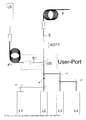
- a switching element US is the optional reflection of another Laser L5, preferably via another optical fiber F1 and shutter S1.
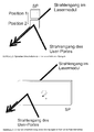
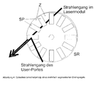
- This switching element US is shown in FIGS. 2 and 3 in different versions shown.
- a mirror SP is pivoted into the beam path (position 2) or pivoted. This leads to the fact that the light of the laser L5 only in the Beam path is reflected when it is actually needed.
- a rectangular mirror element SP becomes fast about a rotation axis A. rotated and thereby passes periodically into the beam path of the coupling part.
- Figure 4 are mirror elements SP 1 on a mirror wheel SR, wherein between the mirrors SP1 spaces Z are located, which are translucent.
- the mirrors SP are fixed or vapor-deposited on a glass pane.
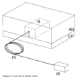
- the coupling module as shown in Figure 5 in a fixed Housing G are arranged on the base plate GP of the laser module is mounted.
- a cover AH covers the laser module inclusive User Port.
- the adjustment of the coverage of the Userport beam path with that of Laser module occurs once when inserting the user port.
- the laser radiation is via a flexible optical fiber F1, preferably as polarization-maintaining single-mode fiber is executed, via a recess led in the cover AH in the housing of the Userportes G.
- the Laser beam coupler LK is provided by the user with the desired laser L5 connected and the laser beam with appropriate mechanical Adjustment devices coupled into the fiber.
Landscapes
- Physics & Mathematics (AREA)
- Chemical & Material Sciences (AREA)
- Analytical Chemistry (AREA)
- General Physics & Mathematics (AREA)
- Optics & Photonics (AREA)
- Microscoopes, Condenser (AREA)
- Mechanical Light Control Or Optical Switches (AREA)
Abstract
Description
ist es bekannt, mehrere Laser über eine Lichtleitfaser in das Laser-Scanning-Mikroskop einzukoppeln.
Claims (10)
- Anordnung im Beleuchtungsstrahlengang eines Laser-Scanning-Mikroskopes, bestehend aus einem in den Strahlengang einbringbaren Spiegel zur Einkopplung mindestens einer Zusatzwellenlänge.
- Anordnung nach Anspruch 1, wobei der Spiegel verschieblich ist.
- Anordnung nach Anspruch 1 oder 2, mit einem Spiegelrad.
- Anordnung nach Anspruch 3, wobei sich auf dem Spiegelrad zwischen angeordneten Spiegeln mindestes ein lichtdurchlässiger Bereich befindet.
- Anordnung nach Anspruch 1 oder 2, wobei ein länglich ausgebildeter Spiegel um eine Drehachse rotierbar ist.
- Anordnung nach einem der vorangehenden Ansprüche, wobei der Spiegel Teil eines Einschubs in den Beleuchtungsmodul ist.
- Anordnung nach Anspruch 6, wobei die Zusatzwellenlänge über eine Lichtleitfaser eingekoppelt wird.
- Wechselbare Schnittstelle im Beleuchtungsstrahlengang eines Laser-Scanning-Mikroskopes, nach einem der vorangehenden Ansprüche.
- Verfahren zum Betrieb eines Laser-Scanning-Mikroskopes mit einem schnell einschwenkbaren Spiegel, insbesondere zum Betrieb einer Anordnung nach einem der vorangehenden Ansprüche, zur Einkopplung mindestens einer zusätzlichen Wellenlänge in den Beleuchtungsstrahlengang,
wobei der Schwenkvorgang über eine Ansteuereinheit so mit der Beleuchtungssteuerung synchronisiert ist, dass bei ausgeschwenkten Spiegel mindestens eine weitere Wellenlänge in den Beleuchtungsstrahlengang eingekoppelt wird. - Verfahren nach Anspruch 9, wobei eine Einkopplung der Beleuchtung in das Mikroskop über mindestens einen AOTF erfolgt, dessen Betrieb mit dem Schaltvorgang synchronisiert ist.
Applications Claiming Priority (2)
| Application Number | Priority Date | Filing Date | Title |
|---|---|---|---|
| DE10332062 | 2003-07-11 | ||
| DE10332062A DE10332062A1 (de) | 2003-07-11 | 2003-07-11 | Anordnung im Beleuchtungsstrahlengang eines Laser-Scanning-Mikroskopes |
Publications (2)
| Publication Number | Publication Date |
|---|---|
| EP1496385A1 true EP1496385A1 (de) | 2005-01-12 |
| EP1496385B1 EP1496385B1 (de) | 2009-05-13 |
Family
ID=33441760
Family Applications (1)
| Application Number | Title | Priority Date | Filing Date |
|---|---|---|---|
| EP04015828A Expired - Lifetime EP1496385B1 (de) | 2003-07-11 | 2004-07-06 | Anordnung im Beleuchtungsstrahlengang eines Laser-Scanning-Mikroskopes |
Country Status (5)
| Country | Link |
|---|---|
| US (1) | US7212337B2 (de) |
| EP (1) | EP1496385B1 (de) |
| JP (1) | JP4660671B2 (de) |
| AT (1) | ATE431572T1 (de) |
| DE (2) | DE10332062A1 (de) |
Families Citing this family (2)
| Publication number | Priority date | Publication date | Assignee | Title |
|---|---|---|---|---|
| US10969571B2 (en) | 2016-05-30 | 2021-04-06 | Eric Swanson | Few-mode fiber endoscope |
| EP3538941B1 (de) | 2016-11-10 | 2025-04-23 | The Trustees of Columbia University in the City of New York | Schnelles hochauflösendes bildgebungsverfahren für grosse proben |
Citations (10)
| Publication number | Priority date | Publication date | Assignee | Title |
|---|---|---|---|---|
| DE4323129A1 (de) * | 1992-07-24 | 1994-02-03 | Zeiss Carl Fa | Lasermikroskop |
| US5581345A (en) * | 1990-12-03 | 1996-12-03 | Nikon Corporation | Confocal laser scanning mode interference contrast microscope, and method of measuring minute step height and apparatus with said microscope |
| DE19702753A1 (de) * | 1997-01-27 | 1998-07-30 | Zeiss Carl Jena Gmbh | Laser-Scanning-Mikroskop |
| US5915823A (en) * | 1995-10-19 | 1999-06-29 | Simon; Jerome H. | Central source light distribution system and components for maintaining beam continuity to adjustably positionable remote illumination directors |
| US5999255A (en) * | 1997-10-09 | 1999-12-07 | Solutia Inc. | Method and apparatus for measuring Raman spectra and physical properties in-situ |
| US6160662A (en) * | 1998-05-29 | 2000-12-12 | Nikon Corporation | Inverted microscope having a variable stage position |
| WO2002015808A1 (de) * | 2000-08-23 | 2002-02-28 | Meister Joerg | Medizinisches laserbehandlungsmodul |
| US6388807B1 (en) * | 1999-10-12 | 2002-05-14 | Leica Microsystems Heidelberg Gmbh | Confocal laser scanning microscope |
| US6437913B1 (en) * | 1999-03-18 | 2002-08-20 | Olympus Optical Co., Ltd. | Laser microscope |
| US6447503B1 (en) * | 1998-01-29 | 2002-09-10 | International Business Machines Corporation | Laser dermablator and dermablation |
Family Cites Families (9)
| Publication number | Priority date | Publication date | Assignee | Title |
|---|---|---|---|---|
| US599255A (en) * | 1898-02-15 | Half to george h | ||
| US3813172A (en) * | 1972-01-03 | 1974-05-28 | Kollmorgen Corp | Photometric device with a plurality of measuring fields |
| US5535052A (en) * | 1992-07-24 | 1996-07-09 | Carl-Zeiss-Stiftung | Laser microscope |
| DK0801985T3 (da) * | 1996-04-19 | 2001-08-06 | Deutz Ag | Højtryksvalsepresse til trykknusning af kornet godsmateriale |
| US6167173A (en) * | 1997-01-27 | 2000-12-26 | Carl Zeiss Jena Gmbh | Laser scanning microscope |
| DE19829981C2 (de) | 1998-07-04 | 2002-10-17 | Zeiss Carl Jena Gmbh | Verfahren und Anordnung zur konfokalen Mikroskopie |
| DE19931954A1 (de) * | 1999-07-10 | 2001-01-11 | Leica Microsystems | Beleuchtungseinrichtung für ein DUV-Mikroskop |
| AU2002230415A1 (en) * | 2000-11-17 | 2002-05-27 | Universal Imaging Corporation | Rapidly changing dichroic beamsplitter |
| DE10229935B4 (de) * | 2002-07-04 | 2018-02-08 | Carl Zeiss Microscopy Gmbh | Mikroskopschieber zur Einkopplung von Licht in ein Mikroskop |
-
2003
- 2003-07-11 DE DE10332062A patent/DE10332062A1/de not_active Withdrawn
-
2004
- 2004-07-02 JP JP2004196312A patent/JP4660671B2/ja not_active Expired - Fee Related
- 2004-07-06 AT AT04015828T patent/ATE431572T1/de not_active IP Right Cessation
- 2004-07-06 EP EP04015828A patent/EP1496385B1/de not_active Expired - Lifetime
- 2004-07-06 DE DE502004009476T patent/DE502004009476D1/de not_active Expired - Lifetime
- 2004-07-09 US US10/888,098 patent/US7212337B2/en not_active Expired - Fee Related
Patent Citations (10)
| Publication number | Priority date | Publication date | Assignee | Title |
|---|---|---|---|---|
| US5581345A (en) * | 1990-12-03 | 1996-12-03 | Nikon Corporation | Confocal laser scanning mode interference contrast microscope, and method of measuring minute step height and apparatus with said microscope |
| DE4323129A1 (de) * | 1992-07-24 | 1994-02-03 | Zeiss Carl Fa | Lasermikroskop |
| US5915823A (en) * | 1995-10-19 | 1999-06-29 | Simon; Jerome H. | Central source light distribution system and components for maintaining beam continuity to adjustably positionable remote illumination directors |
| DE19702753A1 (de) * | 1997-01-27 | 1998-07-30 | Zeiss Carl Jena Gmbh | Laser-Scanning-Mikroskop |
| US5999255A (en) * | 1997-10-09 | 1999-12-07 | Solutia Inc. | Method and apparatus for measuring Raman spectra and physical properties in-situ |
| US6447503B1 (en) * | 1998-01-29 | 2002-09-10 | International Business Machines Corporation | Laser dermablator and dermablation |
| US6160662A (en) * | 1998-05-29 | 2000-12-12 | Nikon Corporation | Inverted microscope having a variable stage position |
| US6437913B1 (en) * | 1999-03-18 | 2002-08-20 | Olympus Optical Co., Ltd. | Laser microscope |
| US6388807B1 (en) * | 1999-10-12 | 2002-05-14 | Leica Microsystems Heidelberg Gmbh | Confocal laser scanning microscope |
| WO2002015808A1 (de) * | 2000-08-23 | 2002-02-28 | Meister Joerg | Medizinisches laserbehandlungsmodul |
Also Published As
| Publication number | Publication date |
|---|---|
| DE502004009476D1 (de) | 2009-06-25 |
| DE10332062A1 (de) | 2005-01-27 |
| EP1496385B1 (de) | 2009-05-13 |
| ATE431572T1 (de) | 2009-05-15 |
| JP2005099717A (ja) | 2005-04-14 |
| US20050046932A1 (en) | 2005-03-03 |
| JP4660671B2 (ja) | 2011-03-30 |
| US7212337B2 (en) | 2007-05-01 |
Similar Documents
| Publication | Publication Date | Title |
|---|---|---|
| DE19510102C1 (de) | Konfokales Fluoreszenzmikroskop | |
| DE102011106916B4 (de) | Konfokales Auflicht-Rastermikroskop, Verfahren und Programm zum Betrieb eines solchen Mikroskops | |
| DE102012017922B4 (de) | Optikanordnung und Lichtmikroskop | |
| DE10105391B4 (de) | Scanmikroskop und Modul für ein Scanmikroskop | |
| JP4206452B2 (ja) | 短パルスレーザーを分散する光ファイバーを有する顕微鏡 | |
| CA2084408C (en) | Illumination system and method for a high definition light microscope | |
| DE69629877T2 (de) | Konfokales Mikroskop | |
| DE19835072A1 (de) | Anordnung zur Beleuchtung und/oder Detektion in einem Mikroskop | |
| DE112004000340T5 (de) | Mikroskopsystem | |
| WO2014060270A2 (de) | Optikanordnung und lichtmikroskop | |
| DE102004016253B4 (de) | Rastermikroskop und Verfahren zur rastermikroskopischen Untersuchung einer Probe | |
| EP3156838A1 (de) | Scannerkopf und vorrichtung mit scannerkopf | |
| DE102017109645A1 (de) | Lichtmikroskop und Verfahren zum Bereitstellen von strukturiertem Beleuchtungslicht | |
| EP1141763B1 (de) | Anordnung zur separierung von anregungs- und emissionslicht in einem mikroskop | |
| DE10247247A1 (de) | Optische Anordnung und Mikroskop | |
| DE102004034961A1 (de) | Lichtrastermikroskop mit linienförmiger Abtastung und Verwendung | |
| DE102004034987A1 (de) | Lichtrastermikroskop und Verwendung | |
| EP1281997B1 (de) | Scanmikroskop | |
| DE4323129A1 (de) | Lasermikroskop | |
| DE10156695A1 (de) | Scanmikroskop, Verfahren zur Scanmikroskopie und Bandpassfilter | |
| DE102004034845B4 (de) | Umschaltbares Mikroskop | |
| EP1496385B1 (de) | Anordnung im Beleuchtungsstrahlengang eines Laser-Scanning-Mikroskopes | |
| WO2008012056A1 (de) | Laser-scanning-mikroskop | |
| DE3821403A1 (de) | Anordnung zum beleuchten und visuellen abtasten eines gegenstandes unter anwendung eines optischen systems | |
| DE102006034914A1 (de) | Verfahren und Anordnung zur Ansteuerung eines Mikroskops, insbesondere eines Laser-Scanning-Mikroskopes |
Legal Events
| Date | Code | Title | Description |
|---|---|---|---|
| PUAI | Public reference made under article 153(3) epc to a published international application that has entered the european phase |
Free format text: ORIGINAL CODE: 0009012 |
|
| 17P | Request for examination filed |
Effective date: 20040706 |
|
| AK | Designated contracting states |
Kind code of ref document: A1 Designated state(s): AT BE BG CH CY CZ DE DK EE ES FI FR GB GR HU IE IT LI LU MC NL PL PT RO SE SI SK TR |
|
| AX | Request for extension of the european patent |
Extension state: AL HR LT LV MK |
|
| 17Q | First examination report despatched |
Effective date: 20050617 |
|
| AKX | Designation fees paid |
Designated state(s): AT BE BG CH CY CZ DE DK EE ES FI FR GB GR HU IE IT LI LU MC NL PL PT RO SE SI SK TR |
|
| 17Q | First examination report despatched |
Effective date: 20050617 |
|
| GRAP | Despatch of communication of intention to grant a patent |
Free format text: ORIGINAL CODE: EPIDOSNIGR1 |
|
| GRAS | Grant fee paid |
Free format text: ORIGINAL CODE: EPIDOSNIGR3 |
|
| GRAA | (expected) grant |
Free format text: ORIGINAL CODE: 0009210 |
|
| RIN1 | Information on inventor provided before grant (corrected) |
Inventor name: WILHELM, STEFAN Inventor name: LANGE, RALPH Inventor name: MEISEL, ULRICH Inventor name: REICH, MATTHIAS |
|
| RAP1 | Party data changed (applicant data changed or rights of an application transferred) |
Owner name: CARL ZEISS MICROIMAGING GMBH |
|
| AK | Designated contracting states |
Kind code of ref document: B1 Designated state(s): AT BE BG CH CY CZ DE DK EE ES FI FR GB GR HU IE IT LI LU MC NL PL PT RO SE SI SK TR |
|
| REG | Reference to a national code |
Ref country code: GB Ref legal event code: FG4D Free format text: NOT ENGLISH |
|
| REG | Reference to a national code |
Ref country code: CH Ref legal event code: EP |
|
| REG | Reference to a national code |
Ref country code: IE Ref legal event code: FG4D |
|
| REF | Corresponds to: |
Ref document number: 502004009476 Country of ref document: DE Date of ref document: 20090625 Kind code of ref document: P |
|
| PG25 | Lapsed in a contracting state [announced via postgrant information from national office to epo] |
Ref country code: ES Free format text: LAPSE BECAUSE OF FAILURE TO SUBMIT A TRANSLATION OF THE DESCRIPTION OR TO PAY THE FEE WITHIN THE PRESCRIBED TIME-LIMIT Effective date: 20090824 Ref country code: FI Free format text: LAPSE BECAUSE OF FAILURE TO SUBMIT A TRANSLATION OF THE DESCRIPTION OR TO PAY THE FEE WITHIN THE PRESCRIBED TIME-LIMIT Effective date: 20090513 Ref country code: PT Free format text: LAPSE BECAUSE OF FAILURE TO SUBMIT A TRANSLATION OF THE DESCRIPTION OR TO PAY THE FEE WITHIN THE PRESCRIBED TIME-LIMIT Effective date: 20090913 |
|
| NLV1 | Nl: lapsed or annulled due to failure to fulfill the requirements of art. 29p and 29m of the patents act | ||
| PG25 | Lapsed in a contracting state [announced via postgrant information from national office to epo] |
Ref country code: SE Free format text: LAPSE BECAUSE OF FAILURE TO SUBMIT A TRANSLATION OF THE DESCRIPTION OR TO PAY THE FEE WITHIN THE PRESCRIBED TIME-LIMIT Effective date: 20090813 Ref country code: NL Free format text: LAPSE BECAUSE OF FAILURE TO SUBMIT A TRANSLATION OF THE DESCRIPTION OR TO PAY THE FEE WITHIN THE PRESCRIBED TIME-LIMIT Effective date: 20090513 Ref country code: SI Free format text: LAPSE BECAUSE OF FAILURE TO SUBMIT A TRANSLATION OF THE DESCRIPTION OR TO PAY THE FEE WITHIN THE PRESCRIBED TIME-LIMIT Effective date: 20090513 Ref country code: PL Free format text: LAPSE BECAUSE OF FAILURE TO SUBMIT A TRANSLATION OF THE DESCRIPTION OR TO PAY THE FEE WITHIN THE PRESCRIBED TIME-LIMIT Effective date: 20090513 |
|
| REG | Reference to a national code |
Ref country code: IE Ref legal event code: FD4D |
|
| PG25 | Lapsed in a contracting state [announced via postgrant information from national office to epo] |
Ref country code: RO Free format text: LAPSE BECAUSE OF FAILURE TO SUBMIT A TRANSLATION OF THE DESCRIPTION OR TO PAY THE FEE WITHIN THE PRESCRIBED TIME-LIMIT Effective date: 20090513 Ref country code: IE Free format text: LAPSE BECAUSE OF FAILURE TO SUBMIT A TRANSLATION OF THE DESCRIPTION OR TO PAY THE FEE WITHIN THE PRESCRIBED TIME-LIMIT Effective date: 20090513 Ref country code: DK Free format text: LAPSE BECAUSE OF FAILURE TO SUBMIT A TRANSLATION OF THE DESCRIPTION OR TO PAY THE FEE WITHIN THE PRESCRIBED TIME-LIMIT Effective date: 20090513 Ref country code: CZ Free format text: LAPSE BECAUSE OF FAILURE TO SUBMIT A TRANSLATION OF THE DESCRIPTION OR TO PAY THE FEE WITHIN THE PRESCRIBED TIME-LIMIT Effective date: 20090513 Ref country code: EE Free format text: LAPSE BECAUSE OF FAILURE TO SUBMIT A TRANSLATION OF THE DESCRIPTION OR TO PAY THE FEE WITHIN THE PRESCRIBED TIME-LIMIT Effective date: 20090513 |
|
| BERE | Be: lapsed |
Owner name: CARL ZEISS MICROIMAGING G.M.B.H. Effective date: 20090731 |
|
| PG25 | Lapsed in a contracting state [announced via postgrant information from national office to epo] |
Ref country code: SK Free format text: LAPSE BECAUSE OF FAILURE TO SUBMIT A TRANSLATION OF THE DESCRIPTION OR TO PAY THE FEE WITHIN THE PRESCRIBED TIME-LIMIT Effective date: 20090513 Ref country code: MC Free format text: LAPSE BECAUSE OF NON-PAYMENT OF DUE FEES Effective date: 20090731 |
|
| REG | Reference to a national code |
Ref country code: CH Ref legal event code: PL |
|
| PLBE | No opposition filed within time limit |
Free format text: ORIGINAL CODE: 0009261 |
|
| STAA | Information on the status of an ep patent application or granted ep patent |
Free format text: STATUS: NO OPPOSITION FILED WITHIN TIME LIMIT |
|
| PG25 | Lapsed in a contracting state [announced via postgrant information from national office to epo] |
Ref country code: BG Free format text: LAPSE BECAUSE OF FAILURE TO SUBMIT A TRANSLATION OF THE DESCRIPTION OR TO PAY THE FEE WITHIN THE PRESCRIBED TIME-LIMIT Effective date: 20090813 |
|
| 26N | No opposition filed |
Effective date: 20100216 |
|
| PG25 | Lapsed in a contracting state [announced via postgrant information from national office to epo] |
Ref country code: LI Free format text: LAPSE BECAUSE OF NON-PAYMENT OF DUE FEES Effective date: 20090731 Ref country code: CH Free format text: LAPSE BECAUSE OF NON-PAYMENT OF DUE FEES Effective date: 20090731 |
|
| PG25 | Lapsed in a contracting state [announced via postgrant information from national office to epo] |
Ref country code: BE Free format text: LAPSE BECAUSE OF NON-PAYMENT OF DUE FEES Effective date: 20090731 |
|
| PG25 | Lapsed in a contracting state [announced via postgrant information from national office to epo] |
Ref country code: GR Free format text: LAPSE BECAUSE OF FAILURE TO SUBMIT A TRANSLATION OF THE DESCRIPTION OR TO PAY THE FEE WITHIN THE PRESCRIBED TIME-LIMIT Effective date: 20090814 |
|
| PG25 | Lapsed in a contracting state [announced via postgrant information from national office to epo] |
Ref country code: AT Free format text: LAPSE BECAUSE OF NON-PAYMENT OF DUE FEES Effective date: 20090706 |
|
| PG25 | Lapsed in a contracting state [announced via postgrant information from national office to epo] |
Ref country code: IT Free format text: LAPSE BECAUSE OF FAILURE TO SUBMIT A TRANSLATION OF THE DESCRIPTION OR TO PAY THE FEE WITHIN THE PRESCRIBED TIME-LIMIT Effective date: 20090513 |
|
| PG25 | Lapsed in a contracting state [announced via postgrant information from national office to epo] |
Ref country code: LU Free format text: LAPSE BECAUSE OF NON-PAYMENT OF DUE FEES Effective date: 20090706 |
|
| PG25 | Lapsed in a contracting state [announced via postgrant information from national office to epo] |
Ref country code: HU Free format text: LAPSE BECAUSE OF FAILURE TO SUBMIT A TRANSLATION OF THE DESCRIPTION OR TO PAY THE FEE WITHIN THE PRESCRIBED TIME-LIMIT Effective date: 20091114 |
|
| PG25 | Lapsed in a contracting state [announced via postgrant information from national office to epo] |
Ref country code: TR Free format text: LAPSE BECAUSE OF FAILURE TO SUBMIT A TRANSLATION OF THE DESCRIPTION OR TO PAY THE FEE WITHIN THE PRESCRIBED TIME-LIMIT Effective date: 20090513 |
|
| PG25 | Lapsed in a contracting state [announced via postgrant information from national office to epo] |
Ref country code: CY Free format text: LAPSE BECAUSE OF FAILURE TO SUBMIT A TRANSLATION OF THE DESCRIPTION OR TO PAY THE FEE WITHIN THE PRESCRIBED TIME-LIMIT Effective date: 20090513 |
|
| REG | Reference to a national code |
Ref country code: DE Ref legal event code: R081 Ref document number: 502004009476 Country of ref document: DE Owner name: CARL ZEISS MICROSCOPY GMBH, DE Free format text: FORMER OWNER: CARL ZEISS MICROIMAGING GMBH, 07745 JENA, DE Effective date: 20130204 |
|
| REG | Reference to a national code |
Ref country code: FR Ref legal event code: PLFP Year of fee payment: 13 |
|
| REG | Reference to a national code |
Ref country code: FR Ref legal event code: PLFP Year of fee payment: 14 |
|
| PGFP | Annual fee paid to national office [announced via postgrant information from national office to epo] |
Ref country code: GB Payment date: 20170719 Year of fee payment: 14 Ref country code: FR Payment date: 20170724 Year of fee payment: 14 Ref country code: DE Payment date: 20170724 Year of fee payment: 14 |
|
| REG | Reference to a national code |
Ref country code: DE Ref legal event code: R119 Ref document number: 502004009476 Country of ref document: DE |
|
| GBPC | Gb: european patent ceased through non-payment of renewal fee |
Effective date: 20180706 |
|
| PG25 | Lapsed in a contracting state [announced via postgrant information from national office to epo] |
Ref country code: GB Free format text: LAPSE BECAUSE OF NON-PAYMENT OF DUE FEES Effective date: 20180706 Ref country code: FR Free format text: LAPSE BECAUSE OF NON-PAYMENT OF DUE FEES Effective date: 20180731 Ref country code: DE Free format text: LAPSE BECAUSE OF NON-PAYMENT OF DUE FEES Effective date: 20190201 |