EP1496280A2 - Verfahren zur Unterdrückung von Rupfschwingungen in einer Reibungskupplung - Google Patents
Verfahren zur Unterdrückung von Rupfschwingungen in einer Reibungskupplung Download PDFInfo
- Publication number
- EP1496280A2 EP1496280A2 EP04014817A EP04014817A EP1496280A2 EP 1496280 A2 EP1496280 A2 EP 1496280A2 EP 04014817 A EP04014817 A EP 04014817A EP 04014817 A EP04014817 A EP 04014817A EP 1496280 A2 EP1496280 A2 EP 1496280A2
- Authority
- EP
- European Patent Office
- Prior art keywords
- clutch
- release system
- actuator
- release
- juddering
- Prior art date
- Legal status (The legal status is an assumption and is not a legal conclusion. Google has not performed a legal analysis and makes no representation as to the accuracy of the status listed.)
- Granted
Links
Images

Classifications
-
- F—MECHANICAL ENGINEERING; LIGHTING; HEATING; WEAPONS; BLASTING
- F16—ENGINEERING ELEMENTS AND UNITS; GENERAL MEASURES FOR PRODUCING AND MAINTAINING EFFECTIVE FUNCTIONING OF MACHINES OR INSTALLATIONS; THERMAL INSULATION IN GENERAL
- F16D—COUPLINGS FOR TRANSMITTING ROTATION; CLUTCHES; BRAKES
- F16D48/00—External control of clutches
- F16D48/06—Control by electric or electronic means, e.g. of fluid pressure
-
- F—MECHANICAL ENGINEERING; LIGHTING; HEATING; WEAPONS; BLASTING
- F16—ENGINEERING ELEMENTS AND UNITS; GENERAL MEASURES FOR PRODUCING AND MAINTAINING EFFECTIVE FUNCTIONING OF MACHINES OR INSTALLATIONS; THERMAL INSULATION IN GENERAL
- F16D—COUPLINGS FOR TRANSMITTING ROTATION; CLUTCHES; BRAKES
- F16D2500/00—External control of clutches by electric or electronic means
- F16D2500/10—System to be controlled
- F16D2500/102—Actuator
- F16D2500/1021—Electrical type
- F16D2500/1023—Electric motor
-
- F—MECHANICAL ENGINEERING; LIGHTING; HEATING; WEAPONS; BLASTING
- F16—ENGINEERING ELEMENTS AND UNITS; GENERAL MEASURES FOR PRODUCING AND MAINTAINING EFFECTIVE FUNCTIONING OF MACHINES OR INSTALLATIONS; THERMAL INSULATION IN GENERAL
- F16D—COUPLINGS FOR TRANSMITTING ROTATION; CLUTCHES; BRAKES
- F16D2500/00—External control of clutches by electric or electronic means
- F16D2500/50—Problem to be solved by the control system
- F16D2500/502—Relating the clutch
- F16D2500/50293—Reduction of vibrations
-
- F—MECHANICAL ENGINEERING; LIGHTING; HEATING; WEAPONS; BLASTING
- F16—ENGINEERING ELEMENTS AND UNITS; GENERAL MEASURES FOR PRODUCING AND MAINTAINING EFFECTIVE FUNCTIONING OF MACHINES OR INSTALLATIONS; THERMAL INSULATION IN GENERAL
- F16D—COUPLINGS FOR TRANSMITTING ROTATION; CLUTCHES; BRAKES
- F16D2500/00—External control of clutches by electric or electronic means
- F16D2500/70—Details about the implementation of the control system
- F16D2500/704—Output parameters from the control unit; Target parameters to be controlled
- F16D2500/70402—Actuator parameters
- F16D2500/7042—Voltage
Definitions
- the present invention relates to a method for suppressing juddering vibrations in a release system for a friction clutch in a drive train of a motor vehicle with a main release system and a secondary release system by an electric motor driven actuator is actuated.
- juddering vibrations can significantly limit the ride comfort and are perceived as unpleasant.
- the juddering vibrations can be reduced in principle by a reduction of the excitation be, for example, by smoother surfaces of the clutch linings or clutch plates etc., but here you come across production limits, so always a residual excitation remains.
- the object of the present invention is therefore to provide the juddering vibrations during a Continue to minimize starting process.
- the disengagement system preferably comprises a hydraulic system with a master cylinder, a slave cylinder and a connecting pressure medium line.
- the Pressure medium line for example, an intermediate piston is arranged, the pressure medium line in a first wiring harness and a second wiring harness shares.
- the intermediate piston is connected to an actuator, so that the pressure in the first wiring harness increased or decreased by applying a force through the actuator to the intermediate piston can be.
- An increase or a decrease in the pressure in the first wiring harness by applying the force through the actuator to the intermediate piston can be dynamic and with quick changes compared to the actual engagement process happen.
- the clutch continues via the slave cylinder opened or closed, as it the position of the clutch pedal of the Driver corresponds.
- the relatively slow Einkupplungsvorgang the first approximation can be viewed statically, is a dynamic opening or closing of the dynamic Coupling superimposed, in a way modulated.
- a balance of Jupschwingungen become.
- suitable measures that point to a juddering vibration, for a Control the dynamically superimposed coupling process to use.
- an intermediate piston With an actuator any shape of a pump or the like can be applied become.
- the master cylinder and the slave cylinder parts of a Hauptausschreibsystems and that of Intermediate piston and the slave cylinder are parts of a secondary release system.
- the hydraulic System therefore has two essentially independent release systems, wherein the slave cylinder belongs to both Aus Havensystemen.
- the main release system is the known system of master cylinder and slave cylinder, the master cylinder is operated for example by a clutch pedal.
- the secondary release system has with the intermediate piston and the associated actuator via its own actuating means comparable to the master cylinder.
- the side release system does not have to be able to be to realize a complete engagement or disengagement via the Nehmeryzlinder.
- the realizable system can alternatively also on act an independent slave cylinder. This can, for example, two complete be provided independent hydraulic systems.
- the secondary release system also e.g. in the form of a hydraulic pump arranged in the pressure medium line be executed. By appropriate control of the hydraulic pump can increase the pressure or -absenkung be effected in the first wiring harness.
- the release system for actuating a friction clutch in a drive train of a Motor vehicle may further include a Heilausschreibsystem and in addition a separate Side release system include. Both main release system and side release system can be carried out completely independently of one another and, for example, a mechanical, hydraulic or electrical central release system or any other known Form of a release system. It is advantageous if the secondary release system parallel to the Hauptausschreibsystem is arranged. In this case, the secondary release system and the Feldausschreibsystem be operated independently. At a simultaneous Actuation overlap the caused by both release systems Kupplungsbetuschistswege.
- the Release system can be provided that the Mauausschreibsystem is arranged in series with the Hauptausschreibsystem. This is special in a Gottausschreibsystem relatively easily realized by e.g. two independent hydraulic or mechanical Gottausschreiber one behind the other are arranged. The release routes and the necessary release forces can be clear be different, so that the secondary release system as in the previously shown Embodiments only for a part of the necessary for a complete separation of the coupling Way can be designed and correspondingly lower forces at the same Ausgur conductedn necessary.
- the Proportionality factor is increased in a ramp. If a juddering vibration is detected, then the proportionality factor remains constant for a certain time and is then increased. Of the increased proportionality factor remains constant again for a certain period of time then raised and so on.
- the Proportionality factor is reduced after the reduction of the juddering vibration. This can also ramped in accordance with the increase of the proportionality factor.
- Fig. 1 shows a schematic representation of a possible embodiment of a hydraulic Systems based on a clutch release device 3 with a master cylinder 4 and a Slave cylinder 5.
- a pressure relief valve 2 is in the embodiment shown in a pressure medium line 39 between a first wiring harness 11 and a second Wiring harness 12 installed and separates both in the open state from each other.
- the pressure relief valve 2 in the Master cylinder 4 or in the slave cylinder 5 can be integrated as well as in other hydraulic Systems such as brake systems, power steering systems, and the like in a Functional component can be integrated.
- an inventive pressure relief valve 2 in each hydraulic line system in an advantageous manner as a pressure relief valve and / or as a vibration filter, for example, as a so-called "Kribbeffilter" of Be an advantage.
- the clutch release system 3 actuates the clutch 7 hydraulically by applying the master cylinder 4 by means of an actuator 14, the foot pedal, an actuator, for example an electric actuator, or the like may be. This is by means of a mechanical transmission 13 pressure in the master cylinder 4 constructed, the on the second Wiring harness 12, via the pressure relief valve 2 and the first power train 11 a Pressure in the slave cylinder 5 builds.
- the slave cylinder 5 can - as shown in the Example - be arranged concentrically around the transmission input shaft 10 and axially support a gearbox, not shown, and the necessary release force on a Release bearing on the clutch 7, or at their release elements such as plate spring, muster.
- Other embodiments may include a slave cylinder 5, which has a Release mechanism actuated a releaser and arranged outside the clutch bell is, provide, this by means of a hydraulic connection with the master cylinder standing in the slave cylinder housing accommodated piston, the release mechanism axially applied.
- To apply the release force of the slave cylinder is fixed to the housing on the gear housing, which is not shown here, or on another housing fixed Component attached.
- the transmission input shaft 10 transmits when the clutch is closed 7 shows the torque of the internal combustion engine 8 on a non-illustrated transmission and subsequently to the drive wheels of a motor vehicle.
- the crankshaft 9 undergoes in Dependence on the design of the internal combustion engine 8, for example in dependence from the number of cylinders, nonuniform loads, resulting in axial and / or tumble oscillations this express and on the release mechanism 6 on the slave cylinder 5, the strands of wire 11, 12 on the master cylinder 4 and from there via the mechanical connection 13 are transmitted to the actuator 14.
- these vibrations are perceived as unpleasant.
- a Actuator as actuator 14 may, for example, a reduced control accuracy or a shortened life may be the result of the vibrations.
- the pressure relief valve 2 is therefore turned on for damping in the lines 11, 12 and for damping of the Crankshaft 9 registered vibrations matched.
- the frequency range of such Vibrations are typically 50 to 200 Hz.
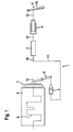
- Fig. 2 shows a schematic diagram of an inventive. Release system. Shown is a schematic diagram of a clutch release device 3 with one or more to the otherwise not shown clutch 7 associated clutch plates 26, which with an on known mechanical connection 27 with a known release bearing 28th is coupled. The release bearing 28 is in turn coupled with a release mechanism 6. In This is indicated by a release lever 29, which on a Side fixed to the housing is rotatably mounted on a bearing 30 and on the other side with a piston 31 of a slave cylinder 5 is connected. The release lever 29 is intended in the Sketch of Fig. 2 initially only clarify that the release bearing 28 by the slave cylinder 5 as an actuating element by a corresponding mechanical coupling substantially is moved axially. In practice, this may e.g.
- a hydraulic Gottausschreiber in which the piston 31 is formed as an annular piston in a known manner is and acts on the release bearing 28, or for example by a so-called mechanical Gottausschreiber, in which a sleeve through a corresponding slotted guide similar to a thread is axially displaced during rotation, wherein the slave cylinder. 5 is connected via a radial lever with the sleeve and by rotation of the lever a axial disengagement of the sleeve and thus the release bearing 28 causes.
- the slave cylinder 5 is corresponding the representation of Fig. 1 via a wiring harness 11, 12 with a master cylinder 4 hydraulically connected.
- the master cylinder is in turn by an actuator 14 actuated, this can be a manually operated clutch pedal, an electric or be pneumatic actuator or the like.
- an intermediate piston 32 is arranged.
- the intermediate piston 32nd separates the first wiring harness 11 from the second wiring harness 12.
- the intermediate piston 32 has on both sides of each a pressure chamber and a corresponding with this hydraulic connection.
- the intermediate piston 32 thus corresponds to the direct mechanical coupling of a master cylinder and a slave cylinder, in the Hydraulic line are inserted and so a mechanical intermediate link for transmission represent hydraulic forces.
- the intermediate piston 32 may, for example, via different have hydraulic cross sections on both strands of wire, thereby resulting in a translation of force and volume between the first and second wiring harness 11, 12 results.
- In the embodiment shown here additionally uses another Actuator 33 to the intermediate piston 32 at.
- the actuator 33 may, for example, electrically or also be driven hydraulically. In the present embodiment is of a electrical actuator gone out.
- the electric actuator 33 is via a mechanical connection 34 connected to the intermediate piston 32.
- the electrically operated actuator 33 is of a control unit 35 driven by a not shown power supply with connected to the electrical system of the motor vehicle and the one or more sensors 36 for controlled variables or measured variables.
- a clutch actuation is now on the one hand by applying force to the master cylinder. 4 possible, on the other hand, the intermediate piston 32 can be acted upon with force.
- the intermediate piston 32 can be operated both in the direction of action of the master cylinder 4, i.e. that the hydraulic pressure generated by the master cylinder 4 is increased and so the clutch is opened, or it can be operated against the master cylinder 4, i. that the Hydraulic pressure in the first wiring harness 11 is reduced or even canceled.
- the combination of the master cylinder 4 with the slave cylinder 5 forms here a first Hydraulic system and thus a first release system, hereinafter referred to as Hauptausschreibsystem 37 is designated.
- An actuation of the master cylinder 4 is, apart from a possible translation by the intermediate piston 32, transmitted to the slave cylinder 5 and causes here directly an actuation of the clutch release device 3.
- the Actuator 33 forms via the mechanical connection 34 together with the intermediate piston 32nd and the slave cylinder 5, a second hydraulic system, hereinafter referred to as Mauausschreibsystem referred to as.
- a clutch actuation is by controlling the actuator 33 and thus of the intermediate piston 32 via the slave cylinder 5 regardless of an operation the master cylinder 4 possible.
- juddering vibrations these are from a suitable sensor 36 detected and read by the control unit 35 and processed.
- a suitable signal for the sensor 36 is e.g. the wheel speed, the transmission speed, the Vehicle longitudinal acceleration, vibrations caused by juddering vibrations or like. If a signal supplied by the sensor 36 from the controller 35 as a Detected signal indicative of juddering, the actuator 33 is controlled and actuated.
- the controller 35 includes for the detection of juddering vibrations a controller, the works according to a corresponding control algorithm, it can also be here, for example to act an expert system or the like.
- Actuator 33 will now be in dynamic phase, Frequency and amplitude controlled, the clutch 7 corresponding to something stronger than is predetermined opened or closed by the master cylinder 4, so that one of the Rupfschwingung counteracting torque fluctuation in the drive train is generated.
- the juddering vibrations are thus by a suitable dynamic change of the drive torque compensated or eradicated in the drive train.
- This moment course or torque fluctuation is through the vehicle clutch by correspondingly stronger Opening and closing and thus generates an increase or decrease of the slip.
- the actuator 33 or the entire secondary release system 38 need not be able to Fully independently open the clutch. Rather, it is sufficient for the intended application if this can disengage only a partial path of the clutch, since the disengagement the Mauausschreibsystems 38 of the disengagement of Hauptausschreibsystems 37 is modulated to a certain extent. During a more or less even engagement For example, the clutch is the current coupling position just a little more closed or opened.
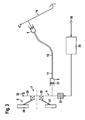
- Fig. 3 shows an alternative embodiment of the release system according to the invention.
- the Side release system 38 is not partially in the hydraulic line of Hauptausschreibsystems here 37 integrated, but directly mechanically connected to the release lever 29.
- the wiring harness 11, 12 in Fig. 3 is for the sake of simplicity without, for example, a pressure relief valve 2 or the like shown.
- the master cylinder 4 forms over the Slave cylinder 5 and the release lever 29 and the release bearing 28 and the mechanical Connection 27 with the clutch disc 26, the Hauptausschreibsystem 37.
- On the release lever 29 acts directly the mechanical actuator 33.
- the connection of slave cylinder. 5 and actuator 33 with the release lever 29 can not shown here via a suitable Overlay mechanism or a crank mechanism or the like done.
- the auxiliary release system 38 is arranged parallel to the main release system 37.
- a Actuation of the secondary release system 38 thus becomes the movement of the main release system 37 superimposed and thus allows modulating small movement fluctuations by the Mauausschreibsystem 38 on the Hauptausschreibsystem 37.
- the forces to be expended the Mauausschreibsystems 38 are compared with the forces to be expended and Because of the Feldausschreibsystems 37 according to the previously described embodiments comparatively low.
- the Hauptausschreibsystem 37 also in series with the Mauausschreibsystem 38 may be arranged.
- the actuator 33 at each point between the intermediate piston 32 and the Release bearing 28 may be arranged.
- the auxiliary release system 38 according to the embodiment 2 can also be integrated directly into the slave cylinder 5.
- N GE_filtered is the filtered transmission input speed which does not include the oscillating component with a pickup frequency, this is a frequency of about 10 Hz in first gear.
- N GE is the transmission input speed.
- the clutch torque M Coupling M off_Pedalposition - KM ⁇ • N be modulated.
- K is the constant that defines the amount of damping.
- M clutch is the clutch torque
- M off_p pedal position is the substantially constant torque that results from the respective clutch slip.
- the modulation X mod K x ⁇ N is realized by a path specification.
- the actuator has a small equivalent mass and is arranged in the release system so that it must move as small a mass as possible in the sense of the equivalent system without translations.
- the first partial natural frequency of the subsystem in which the path modulation is desired thus from the clutch to the actuator, remains high enough to be related to the force vibrating at the picking frequency x mod ⁇ F to accept.
- the condition of a small equivalent actuator mass ME can be easily satisfied.
- the electric motor and the translation of the translatory movement can be chosen so that the actuator force is large enough and the mass remains small. If this is true, then x mod ⁇ M ⁇ I, where M is the moment of the electric motor and I is the current.
- the path modulation is proportional to the voltage U x mod ⁇ M ⁇ I ⁇ U.
- the factor KU can be increased in steps after the check detection if • N is large enough to counteract. After the reduction of the plucking it makes sense to reduce the factor K U in order to stimulate the release system as little as possible.
Landscapes
- Engineering & Computer Science (AREA)
- General Engineering & Computer Science (AREA)
- Physics & Mathematics (AREA)
- Fluid Mechanics (AREA)
- Mechanical Engineering (AREA)
- Hydraulic Clutches, Magnetic Clutches, Fluid Clutches, And Fluid Joints (AREA)
- Mechanical Operated Clutches (AREA)
- Braking Arrangements (AREA)
Abstract
Description
Claims (4)
- Verfahren zur Unterdrückung von Rupfschwingungen in einem Ausrücksystem für eine Reibungskupplung in einem Antriebsstrang eines Kraftfahrzeuges mit einem Hauptausrücksystem (37) und einem Nebenausrücksystem (38), das durch einen elektromotorisch angetriebenen Aktor (33) betätigbar ist, dadurch gekennzeichnet, dass die Antriebsspannung des elektromotorisch angetriebenen Aktors (33) proportional zu einer Rupfdrehzahl ist.
- Verfahren nach dem vorhergehenden Anspruch, dadurch gekennzeichnet, dass der Proportionalitätsfaktor rampenförmig erhöht wird.
- Verfahren nach einem der vorhergehenden Ansprüche, dadurch gekennzeichnet, dass der Proportionalitätsfaktor nach der Reduzierung der Rupfschwingung verringert wird.
- Ausrücksystem zur Betätigung einer Reibungskupplung in einem Antriebsstrang eines Kraftfahrzeuges mit einem Hauptausrücksystem (37) und einem Nebenausrücksystem (38), das durch einen elektromotorisch angetriebenen Aktor (33) betätigbar ist, dadurch gekennzeichnet, dass die Antriebsspannung des elektromotorisch angetriebenen Aktors (33) proportional zu einer Rupfdrehzahl ist.
Applications Claiming Priority (2)
| Application Number | Priority Date | Filing Date | Title |
|---|---|---|---|
| DE10330896 | 2003-07-09 | ||
| DE10330896 | 2003-07-09 |
Publications (3)
| Publication Number | Publication Date |
|---|---|
| EP1496280A2 true EP1496280A2 (de) | 2005-01-12 |
| EP1496280A3 EP1496280A3 (de) | 2005-06-01 |
| EP1496280B1 EP1496280B1 (de) | 2007-07-11 |
Family
ID=33441670
Family Applications (1)
| Application Number | Title | Priority Date | Filing Date |
|---|---|---|---|
| EP04014817A Expired - Lifetime EP1496280B1 (de) | 2003-07-09 | 2004-06-24 | Verfahren zur Unterdrückung von Rupfschwingungen in einer Reibungskupplung |
Country Status (3)
| Country | Link |
|---|---|
| EP (1) | EP1496280B1 (de) |
| AT (1) | ATE366880T1 (de) |
| DE (2) | DE502004004276D1 (de) |
Cited By (2)
| Publication number | Priority date | Publication date | Assignee | Title |
|---|---|---|---|---|
| WO2009003454A3 (de) * | 2007-07-05 | 2009-03-12 | Luk Lamellen & Kupplungsbau | Verfahren und vorrichtung zum regeln des schlupfes einer fahrzeugkupplung |
| EP1850027A3 (de) * | 2006-04-29 | 2010-07-14 | LuK Lamellen und Kupplungsbau Beteiligungs KG | Hydraulisches System |
Families Citing this family (3)
| Publication number | Priority date | Publication date | Assignee | Title |
|---|---|---|---|---|
| DE102007006803B4 (de) | 2006-03-08 | 2019-04-18 | Schaeffler Technologies AG & Co. KG | Verfahren und Vorrichtung zum Vermindern von Rupfschwingungen in einem Kraftfahrzeugantriebsstrang |
| DE112007001156B4 (de) * | 2006-06-01 | 2016-03-31 | Schaeffler Technologies AG & Co. KG | Strömungselement für ein hydraulisches System |
| DE102014204343B4 (de) | 2014-03-10 | 2021-04-29 | Zf Friedrichshafen Ag | Verfahren und Vorrichtung zur Steuerung einer automatisierten Reibungskupplung |
Family Cites Families (3)
| Publication number | Priority date | Publication date | Assignee | Title |
|---|---|---|---|---|
| DE10081015B4 (de) * | 1999-04-15 | 2016-08-18 | Schaeffler Technologies AG & Co. KG | Betätigungsvorrichtung |
| DE10041387A1 (de) * | 2000-08-23 | 2002-03-07 | Daimler Chrysler Ag | Antriebsstrang eines Kraftfahrzeuges |
| US8831847B2 (en) * | 2001-08-24 | 2014-09-09 | Schaeffler Technologies AG & Co. KG | Regulated drivetrain for damping out vibrations |
-
2004
- 2004-06-24 EP EP04014817A patent/EP1496280B1/de not_active Expired - Lifetime
- 2004-06-24 DE DE502004004276T patent/DE502004004276D1/de not_active Expired - Lifetime
- 2004-06-24 AT AT04014817T patent/ATE366880T1/de not_active IP Right Cessation
- 2004-06-24 DE DE102004030479A patent/DE102004030479A1/de not_active Withdrawn
Cited By (3)
| Publication number | Priority date | Publication date | Assignee | Title |
|---|---|---|---|---|
| EP1850027A3 (de) * | 2006-04-29 | 2010-07-14 | LuK Lamellen und Kupplungsbau Beteiligungs KG | Hydraulisches System |
| WO2009003454A3 (de) * | 2007-07-05 | 2009-03-12 | Luk Lamellen & Kupplungsbau | Verfahren und vorrichtung zum regeln des schlupfes einer fahrzeugkupplung |
| US7813858B2 (en) | 2007-07-05 | 2010-10-12 | Luk Lamellen Und Kupplungsbau Beteiligungs Kg | Method and device for controlling the slip of a vehicle clutch |
Also Published As
| Publication number | Publication date |
|---|---|
| EP1496280B1 (de) | 2007-07-11 |
| DE102004030479A1 (de) | 2005-01-27 |
| ATE366880T1 (de) | 2007-08-15 |
| EP1496280A3 (de) | 2005-06-01 |
| DE502004004276D1 (de) | 2007-08-23 |
Similar Documents
| Publication | Publication Date | Title |
|---|---|---|
| EP2090797B1 (de) | Ansteuerverfahren für eine Fahrzeugkupplung | |
| EP2504211B1 (de) | Verfahren und vorrichtung zum betreiben eines hybridfahrzeuges | |
| DE102017111077A1 (de) | Bremsvorrichtung, insbesondere für elektrisch angetriebene Kraftfahrzeuge | |
| DE19721034A1 (de) | Kraftfahrzeug | |
| WO2016146121A1 (de) | Hydraulikanordnung für eine hydraulisch betätigte reibkupplung und verfahren zum betätigen einer hydraulisch betätigten reibkupplung | |
| DE10325354A1 (de) | Verfahren zum Betrieb eines Antriebsstrangs eines Kraftfahrzeugs | |
| DE102017215684A1 (de) | Steuervorrichtung für ein fahrzeug | |
| DE102018126717A1 (de) | Steuersystem für ein stufenloses getriebe in einem fahrzeugantriebssystem | |
| EP0928376B1 (de) | Automatisch gesteuerte kupplung | |
| DE102014222948A1 (de) | Verfahren zum Ermitteln eines Soll-Wertes eines Betätigungsstroms | |
| EP1496280B1 (de) | Verfahren zur Unterdrückung von Rupfschwingungen in einer Reibungskupplung | |
| DE10017007A1 (de) | Betätigungsvorrichtung | |
| AT503595B1 (de) | Als montageeinheit ausgebildete kupplungsbetätigung | |
| EP1422433A2 (de) | Hydraulisches System | |
| EP3126699B1 (de) | Kupplungsbetätigungsvorrichtung | |
| WO2007099035A1 (de) | Druckregelungsvorrichtung für ein betätigungsmittel | |
| EP2576306A1 (de) | Verfahren zum betreiben eines antriebsstrangs | |
| AT511871A2 (de) | Drehmomentübertragungsvorrichtung für ein Motorfahrzeug, enthaltend ein elektromagnetisches Betätigungssystem mit Kraftrückkopplungssteuerung mit Hilfe eines piezoelektrischen Rings und Verfahren zum Steuern eines entsprechenden Betätigungssystems | |
| DE10043413B4 (de) | Kraftfahrzeug | |
| DE102009029414A1 (de) | Verfahren und Vorrichtung zur Verbesserung der Genauigkeit eines Kupplungsmomentes einer Kupplung in einem automatisierten Kupplungssystem in einem Kraftfahrzeug | |
| WO2001001007A1 (de) | Kupplungsvorrichtung | |
| DE102006034936A1 (de) | Kraftfahrzeug | |
| DE102004019488A1 (de) | Antriebsstrang insbesondere für ein Kraftfahrzeug | |
| DE102006019976A1 (de) | Ausrücksystem für Kupplungen | |
| WO2005064208A1 (de) | Verfahren zum betrieb eines antriebsstrangs eines kraftfahrzeugs |
Legal Events
| Date | Code | Title | Description |
|---|---|---|---|
| PUAI | Public reference made under article 153(3) epc to a published international application that has entered the european phase |
Free format text: ORIGINAL CODE: 0009012 |
|
| AK | Designated contracting states |
Kind code of ref document: A2 Designated state(s): AT BE BG CH CY CZ DE DK EE ES FI FR GB GR HU IE IT LI LU MC NL PL PT RO SE SI SK TR |
|
| AX | Request for extension of the european patent |
Extension state: AL HR LT LV MK |
|
| PUAL | Search report despatched |
Free format text: ORIGINAL CODE: 0009013 |
|
| AK | Designated contracting states |
Kind code of ref document: A3 Designated state(s): AT BE BG CH CY CZ DE DK EE ES FI FR GB GR HU IE IT LI LU MC NL PL PT RO SE SI SK TR |
|
| AX | Request for extension of the european patent |
Extension state: AL HR LT LV MK |
|
| 17P | Request for examination filed |
Effective date: 20051201 |
|
| AKX | Designation fees paid |
Designated state(s): AT BE BG CH CY CZ DE DK EE ES FI FR GB GR HU IE IT LI LU MC NL PL PT RO SE SI SK TR |
|
| 17Q | First examination report despatched |
Effective date: 20060123 |
|
| GRAP | Despatch of communication of intention to grant a patent |
Free format text: ORIGINAL CODE: EPIDOSNIGR1 |
|
| GRAS | Grant fee paid |
Free format text: ORIGINAL CODE: EPIDOSNIGR3 |
|
| GRAA | (expected) grant |
Free format text: ORIGINAL CODE: 0009210 |
|
| AK | Designated contracting states |
Kind code of ref document: B1 Designated state(s): AT BE BG CH CY CZ DE DK EE ES FI FR GB GR HU IE IT LI LU MC NL PL PT RO SE SI SK TR |
|
| REG | Reference to a national code |
Ref country code: GB Ref legal event code: FG4D Free format text: NOT ENGLISH |
|
| REG | Reference to a national code |
Ref country code: CH Ref legal event code: EP |
|
| REF | Corresponds to: |
Ref document number: 502004004276 Country of ref document: DE Date of ref document: 20070823 Kind code of ref document: P |
|
| REG | Reference to a national code |
Ref country code: IE Ref legal event code: FG4D Free format text: LANGUAGE OF EP DOCUMENT: GERMAN |
|
| ET | Fr: translation filed | ||
| PG25 | Lapsed in a contracting state [announced via postgrant information from national office to epo] |
Ref country code: NL Free format text: LAPSE BECAUSE OF FAILURE TO SUBMIT A TRANSLATION OF THE DESCRIPTION OR TO PAY THE FEE WITHIN THE PRESCRIBED TIME-LIMIT Effective date: 20070711 Ref country code: PT Free format text: LAPSE BECAUSE OF FAILURE TO SUBMIT A TRANSLATION OF THE DESCRIPTION OR TO PAY THE FEE WITHIN THE PRESCRIBED TIME-LIMIT Effective date: 20071211 Ref country code: ES Free format text: LAPSE BECAUSE OF FAILURE TO SUBMIT A TRANSLATION OF THE DESCRIPTION OR TO PAY THE FEE WITHIN THE PRESCRIBED TIME-LIMIT Effective date: 20071022 Ref country code: BG Free format text: LAPSE BECAUSE OF FAILURE TO SUBMIT A TRANSLATION OF THE DESCRIPTION OR TO PAY THE FEE WITHIN THE PRESCRIBED TIME-LIMIT Effective date: 20071011 Ref country code: FI Free format text: LAPSE BECAUSE OF FAILURE TO SUBMIT A TRANSLATION OF THE DESCRIPTION OR TO PAY THE FEE WITHIN THE PRESCRIBED TIME-LIMIT Effective date: 20070711 |
|
| NLV1 | Nl: lapsed or annulled due to failure to fulfill the requirements of art. 29p and 29m of the patents act | ||
| GBV | Gb: ep patent (uk) treated as always having been void in accordance with gb section 77(7)/1977 [no translation filed] |
Effective date: 20070711 |
|
| PG25 | Lapsed in a contracting state [announced via postgrant information from national office to epo] |
Ref country code: PL Free format text: LAPSE BECAUSE OF FAILURE TO SUBMIT A TRANSLATION OF THE DESCRIPTION OR TO PAY THE FEE WITHIN THE PRESCRIBED TIME-LIMIT Effective date: 20070711 |
|
| REG | Reference to a national code |
Ref country code: IE Ref legal event code: FD4D |
|
| PG25 | Lapsed in a contracting state [announced via postgrant information from national office to epo] |
Ref country code: DK Free format text: LAPSE BECAUSE OF FAILURE TO SUBMIT A TRANSLATION OF THE DESCRIPTION OR TO PAY THE FEE WITHIN THE PRESCRIBED TIME-LIMIT Effective date: 20070711 Ref country code: GR Free format text: LAPSE BECAUSE OF FAILURE TO SUBMIT A TRANSLATION OF THE DESCRIPTION OR TO PAY THE FEE WITHIN THE PRESCRIBED TIME-LIMIT Effective date: 20071012 |
|
| PLBE | No opposition filed within time limit |
Free format text: ORIGINAL CODE: 0009261 |
|
| STAA | Information on the status of an ep patent application or granted ep patent |
Free format text: STATUS: NO OPPOSITION FILED WITHIN TIME LIMIT |
|
| PG25 | Lapsed in a contracting state [announced via postgrant information from national office to epo] |
Ref country code: SK Free format text: LAPSE BECAUSE OF FAILURE TO SUBMIT A TRANSLATION OF THE DESCRIPTION OR TO PAY THE FEE WITHIN THE PRESCRIBED TIME-LIMIT Effective date: 20070711 Ref country code: GB Free format text: LAPSE BECAUSE OF FAILURE TO SUBMIT A TRANSLATION OF THE DESCRIPTION OR TO PAY THE FEE WITHIN THE PRESCRIBED TIME-LIMIT Effective date: 20070711 Ref country code: CZ Free format text: LAPSE BECAUSE OF FAILURE TO SUBMIT A TRANSLATION OF THE DESCRIPTION OR TO PAY THE FEE WITHIN THE PRESCRIBED TIME-LIMIT Effective date: 20070711 Ref country code: IE Free format text: LAPSE BECAUSE OF FAILURE TO SUBMIT A TRANSLATION OF THE DESCRIPTION OR TO PAY THE FEE WITHIN THE PRESCRIBED TIME-LIMIT Effective date: 20070711 |
|
| 26N | No opposition filed |
Effective date: 20080414 |
|
| PG25 | Lapsed in a contracting state [announced via postgrant information from national office to epo] |
Ref country code: RO Free format text: LAPSE BECAUSE OF FAILURE TO SUBMIT A TRANSLATION OF THE DESCRIPTION OR TO PAY THE FEE WITHIN THE PRESCRIBED TIME-LIMIT Effective date: 20070711 Ref country code: SE Free format text: LAPSE BECAUSE OF FAILURE TO SUBMIT A TRANSLATION OF THE DESCRIPTION OR TO PAY THE FEE WITHIN THE PRESCRIBED TIME-LIMIT Effective date: 20071011 |
|
| BERE | Be: lapsed |
Owner name: LUK LAMELLEN UND KUPPLUNGSBAU BETEILIGUNGS K.G. Effective date: 20080630 |
|
| PG25 | Lapsed in a contracting state [announced via postgrant information from national office to epo] |
Ref country code: MC Free format text: LAPSE BECAUSE OF NON-PAYMENT OF DUE FEES Effective date: 20080630 |
|
| REG | Reference to a national code |
Ref country code: CH Ref legal event code: PL |
|
| PG25 | Lapsed in a contracting state [announced via postgrant information from national office to epo] |
Ref country code: BE Free format text: LAPSE BECAUSE OF NON-PAYMENT OF DUE FEES Effective date: 20080630 |
|
| PG25 | Lapsed in a contracting state [announced via postgrant information from national office to epo] |
Ref country code: EE Free format text: LAPSE BECAUSE OF FAILURE TO SUBMIT A TRANSLATION OF THE DESCRIPTION OR TO PAY THE FEE WITHIN THE PRESCRIBED TIME-LIMIT Effective date: 20070711 |
|
| PG25 | Lapsed in a contracting state [announced via postgrant information from national office to epo] |
Ref country code: SI Free format text: LAPSE BECAUSE OF FAILURE TO SUBMIT A TRANSLATION OF THE DESCRIPTION OR TO PAY THE FEE WITHIN THE PRESCRIBED TIME-LIMIT Effective date: 20070711 Ref country code: LI Free format text: LAPSE BECAUSE OF NON-PAYMENT OF DUE FEES Effective date: 20080630 Ref country code: CH Free format text: LAPSE BECAUSE OF NON-PAYMENT OF DUE FEES Effective date: 20080630 |
|
| PG25 | Lapsed in a contracting state [announced via postgrant information from national office to epo] |
Ref country code: CY Free format text: LAPSE BECAUSE OF FAILURE TO SUBMIT A TRANSLATION OF THE DESCRIPTION OR TO PAY THE FEE WITHIN THE PRESCRIBED TIME-LIMIT Effective date: 20070711 |
|
| PG25 | Lapsed in a contracting state [announced via postgrant information from national office to epo] |
Ref country code: AT Free format text: LAPSE BECAUSE OF NON-PAYMENT OF DUE FEES Effective date: 20080624 |
|
| PG25 | Lapsed in a contracting state [announced via postgrant information from national office to epo] |
Ref country code: HU Free format text: LAPSE BECAUSE OF FAILURE TO SUBMIT A TRANSLATION OF THE DESCRIPTION OR TO PAY THE FEE WITHIN THE PRESCRIBED TIME-LIMIT Effective date: 20080112 Ref country code: LU Free format text: LAPSE BECAUSE OF NON-PAYMENT OF DUE FEES Effective date: 20080624 |
|
| PG25 | Lapsed in a contracting state [announced via postgrant information from national office to epo] |
Ref country code: TR Free format text: LAPSE BECAUSE OF FAILURE TO SUBMIT A TRANSLATION OF THE DESCRIPTION OR TO PAY THE FEE WITHIN THE PRESCRIBED TIME-LIMIT Effective date: 20070711 |
|
| PG25 | Lapsed in a contracting state [announced via postgrant information from national office to epo] |
Ref country code: IT Free format text: LAPSE BECAUSE OF NON-PAYMENT OF DUE FEES Effective date: 20080630 |
|
| REG | Reference to a national code |
Ref country code: DE Ref legal event code: R081 Ref document number: 502004004276 Country of ref document: DE Owner name: SCHAEFFLER TECHNOLOGIES AG & CO. KG, DE Free format text: FORMER OWNER: SCHAEFFLER TECHNOLOGIES GMBH & CO. KG, 91074 HERZOGENAURACH, DE Effective date: 20120828 Ref country code: DE Ref legal event code: R081 Ref document number: 502004004276 Country of ref document: DE Owner name: SCHAEFFLER TECHNOLOGIES GMBH & CO. KG, DE Free format text: FORMER OWNER: SCHAEFFLER TECHNOLOGIES GMBH & CO. KG, 91074 HERZOGENAURACH, DE Effective date: 20120828 |
|
| REG | Reference to a national code |
Ref country code: FR Ref legal event code: TP Owner name: SCHAEFFLER TECHNOLOGIES AG & CO. KG, DE Effective date: 20130408 |
|
| REG | Reference to a national code |
Ref country code: DE Ref legal event code: R081 Ref document number: 502004004276 Country of ref document: DE Owner name: SCHAEFFLER TECHNOLOGIES GMBH & CO. KG, DE Free format text: FORMER OWNER: SCHAEFFLER TECHNOLOGIES AG & CO. KG, 91074 HERZOGENAURACH, DE Effective date: 20140213 Ref country code: DE Ref legal event code: R081 Ref document number: 502004004276 Country of ref document: DE Owner name: SCHAEFFLER TECHNOLOGIES AG & CO. KG, DE Free format text: FORMER OWNER: SCHAEFFLER TECHNOLOGIES AG & CO. KG, 91074 HERZOGENAURACH, DE Effective date: 20140213 |
|
| REG | Reference to a national code |
Ref country code: DE Ref legal event code: R081 Ref document number: 502004004276 Country of ref document: DE Owner name: SCHAEFFLER TECHNOLOGIES AG & CO. KG, DE Free format text: FORMER OWNER: SCHAEFFLER TECHNOLOGIES GMBH & CO. KG, 91074 HERZOGENAURACH, DE Effective date: 20150126 |
|
| REG | Reference to a national code |
Ref country code: FR Ref legal event code: PLFP Year of fee payment: 13 |
|
| REG | Reference to a national code |
Ref country code: FR Ref legal event code: PLFP Year of fee payment: 14 |
|
| PGFP | Annual fee paid to national office [announced via postgrant information from national office to epo] |
Ref country code: FR Payment date: 20170630 Year of fee payment: 14 |
|
| PGFP | Annual fee paid to national office [announced via postgrant information from national office to epo] |
Ref country code: DE Payment date: 20170831 Year of fee payment: 14 |
|
| REG | Reference to a national code |
Ref country code: DE Ref legal event code: R119 Ref document number: 502004004276 Country of ref document: DE |
|
| PG25 | Lapsed in a contracting state [announced via postgrant information from national office to epo] |
Ref country code: FR Free format text: LAPSE BECAUSE OF NON-PAYMENT OF DUE FEES Effective date: 20180630 Ref country code: DE Free format text: LAPSE BECAUSE OF NON-PAYMENT OF DUE FEES Effective date: 20190101 |
|
| P01 | Opt-out of the competence of the unified patent court (upc) registered |
Effective date: 20230523 |