EP1496237A1 - System to control combustion noise of a diesel engine - Google Patents
System to control combustion noise of a diesel engine Download PDFInfo
- Publication number
- EP1496237A1 EP1496237A1 EP04291699A EP04291699A EP1496237A1 EP 1496237 A1 EP1496237 A1 EP 1496237A1 EP 04291699 A EP04291699 A EP 04291699A EP 04291699 A EP04291699 A EP 04291699A EP 1496237 A1 EP1496237 A1 EP 1496237A1
- Authority
- EP
- European Patent Office
- Prior art keywords
- cylinder
- pilot
- during
- pressure
- value
- Prior art date
- Legal status (The legal status is an assumption and is not a legal conclusion. Google has not performed a legal analysis and makes no representation as to the accuracy of the status listed.)
- Granted
Links
Images


Classifications
-
- F—MECHANICAL ENGINEERING; LIGHTING; HEATING; WEAPONS; BLASTING
- F02—COMBUSTION ENGINES; HOT-GAS OR COMBUSTION-PRODUCT ENGINE PLANTS
- F02D—CONTROLLING COMBUSTION ENGINES
- F02D41/00—Electrical control of supply of combustible mixture or its constituents
- F02D41/30—Controlling fuel injection
- F02D41/38—Controlling fuel injection of the high pressure type
- F02D41/40—Controlling fuel injection of the high pressure type with means for controlling injection timing or duration
- F02D41/402—Multiple injections
- F02D41/403—Multiple injections with pilot injections
-
- F—MECHANICAL ENGINEERING; LIGHTING; HEATING; WEAPONS; BLASTING
- F02—COMBUSTION ENGINES; HOT-GAS OR COMBUSTION-PRODUCT ENGINE PLANTS
- F02D—CONTROLLING COMBUSTION ENGINES
- F02D35/00—Controlling engines, dependent on conditions exterior or interior to engines, not otherwise provided for
- F02D35/02—Controlling engines, dependent on conditions exterior or interior to engines, not otherwise provided for on interior conditions
- F02D35/023—Controlling engines, dependent on conditions exterior or interior to engines, not otherwise provided for on interior conditions by determining the cylinder pressure
-
- F—MECHANICAL ENGINEERING; LIGHTING; HEATING; WEAPONS; BLASTING
- F02—COMBUSTION ENGINES; HOT-GAS OR COMBUSTION-PRODUCT ENGINE PLANTS
- F02D—CONTROLLING COMBUSTION ENGINES
- F02D41/00—Electrical control of supply of combustible mixture or its constituents
- F02D41/02—Circuit arrangements for generating control signals
- F02D41/14—Introducing closed-loop corrections
- F02D41/1401—Introducing closed-loop corrections characterised by the control or regulation method
- F02D2041/1413—Controller structures or design
- F02D2041/1432—Controller structures or design the system including a filter, e.g. a low pass or high pass filter
-
- F—MECHANICAL ENGINEERING; LIGHTING; HEATING; WEAPONS; BLASTING
- F02—COMBUSTION ENGINES; HOT-GAS OR COMBUSTION-PRODUCT ENGINE PLANTS
- F02D—CONTROLLING COMBUSTION ENGINES
- F02D2200/00—Input parameters for engine control
- F02D2200/02—Input parameters for engine control the parameters being related to the engine
- F02D2200/025—Engine noise, e.g. determined by using an acoustic sensor
-
- F—MECHANICAL ENGINEERING; LIGHTING; HEATING; WEAPONS; BLASTING
- F02—COMBUSTION ENGINES; HOT-GAS OR COMBUSTION-PRODUCT ENGINE PLANTS
- F02D—CONTROLLING COMBUSTION ENGINES
- F02D41/00—Electrical control of supply of combustible mixture or its constituents
- F02D41/02—Circuit arrangements for generating control signals
- F02D41/14—Introducing closed-loop corrections
- F02D41/1497—With detection of the mechanical response of the engine
-
- F—MECHANICAL ENGINEERING; LIGHTING; HEATING; WEAPONS; BLASTING
- F02—COMBUSTION ENGINES; HOT-GAS OR COMBUSTION-PRODUCT ENGINE PLANTS
- F02D—CONTROLLING COMBUSTION ENGINES
- F02D41/00—Electrical control of supply of combustible mixture or its constituents
- F02D41/30—Controlling fuel injection
- F02D41/38—Controlling fuel injection of the high pressure type
- F02D41/3809—Common rail control systems
- F02D41/3827—Common rail control systems for diesel engines
-
- Y—GENERAL TAGGING OF NEW TECHNOLOGICAL DEVELOPMENTS; GENERAL TAGGING OF CROSS-SECTIONAL TECHNOLOGIES SPANNING OVER SEVERAL SECTIONS OF THE IPC; TECHNICAL SUBJECTS COVERED BY FORMER USPC CROSS-REFERENCE ART COLLECTIONS [XRACs] AND DIGESTS
- Y02—TECHNOLOGIES OR APPLICATIONS FOR MITIGATION OR ADAPTATION AGAINST CLIMATE CHANGE
- Y02T—CLIMATE CHANGE MITIGATION TECHNOLOGIES RELATED TO TRANSPORTATION
- Y02T10/00—Road transport of goods or passengers
- Y02T10/10—Internal combustion engine [ICE] based vehicles
- Y02T10/40—Engine management systems
Definitions
- the present invention relates to a system for controlling the noise of combustion of a diesel engine of a motor vehicle.
- this system relates to setpoint optimization injection system for a diesel engine comprising fuel supply means , for example with a common rail, of the motor in the form of multiple injections of fuel in each cylinder of it to minimize the noise of combustion.
- Diesel Current defects of this type of engine injection systems Diesel are on the one hand a dispersion of the characteristics of the engine output from manufacturing, for example because of manufacturing tolerances and extremely of the system, and secondly a drift in time, during the use of the vehicle, the characteristic in injectors flow. Moreover, the characteristics of the engine itself evolve during its life, as example the compression ratio in the cylinders, the permeability of the valves or segments, which modifies the thermodynamic conditions of combustion. The sum of these drifts results in a degradation of the combustion noise of the engine directly felt by the user of the vehicle.
- EP 0 959 237 B1 discloses a method of resetting the dead time to the injection using an accelerometer. Other methods are known to reset pilot flow rates based on the engine speed sensor.
- the pilot injection is used to inject a small amount of fuel a few milliseconds before the main fuel injection, to minimize the combustion noise. Indeed this small amount of fuel conditions favorably the characteristics of inflammation of the amount of fuel injected during the main injection by a decrease in the pressure gradients responsible combustion noise.
- the engine model used can become obsolete as the engine characteristics change over time, implying that the model is no longer representative after a some time, unless you regularly update its settings, which Here again supposes an increase in the degree of complexity.
- the European patent application EP-A-1 209 458 relates to a method of determining combustion noise by using the method wavelets.
- This method certainly avoids the use of the model of the human ear and does not use directly when calculating the noise note the engine model.
- this method remains difficult to apply simple. Indeed, this approach remains a model-based approach mathematical engine, if only for the choice of the base functions, and is therefore subject to the same disadvantages of using a model.
- this approach remains expensive in computing time because it requires several successive digital filtering to obtain useful information for the control of the injection. Moreover, the sudden dispersion of the values is even more important than for the "IEPC" method.
- the object of the present invention is to solve the aforementioned problems by proposing a non-model based approach, effective in minimizing combustion noise, applicable simply and very little costly in terms of complexity and calculation time.
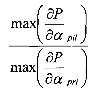
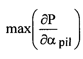
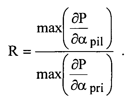
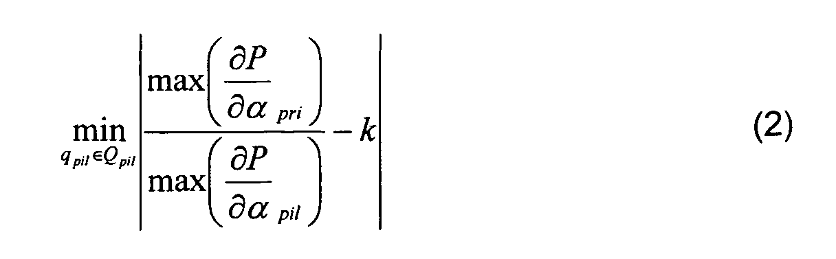
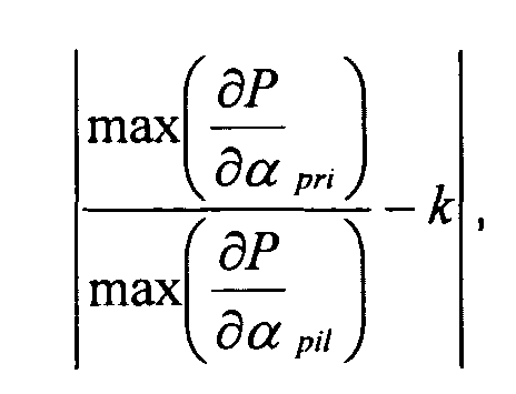
- the system is characterized in that the means for determining the quantity of fuel injected into the cylinder during the pilot injection are adapted to determine, by the implementation of an optimization algorithm, a quantity of fuel injected per cylinder during the pilot injection according to the relationships: where q pil is the quantity of fuel injected into a cylinder during pilot injection, Q pil is a predetermined set of allowable values of q pil , a is the crankshaft angle of the cylinder, ⁇ P / ⁇ pil is the gradient pressure in the cylinder during the pilot injection phase of the cylinder cycle, ⁇ P / ⁇ pri is the pressure gradient in the cylinder during the main injection phase of the cylinder cycle, k is a set value for the ratio and is a characteristic function of a predetermined area of allocation of permissible values for the pair of values
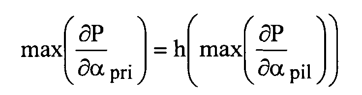
- the system is characterized in that the law of travel of the predetermined set of allowable values of the quantity of fuel injected during the pilot injection is determined by the characteristics of a thermodynamic model according to the relation: where h is the thermodynamic model representative of the evolution of the value of the maximum of the pressure gradient in a cylinder during the main injection phase as a function of the values of the maximum of the pressure gradient in a cylinder during the pilot injection phase .
- the system is characterized in that comprises a pressure sensor associated with each cylinder connected to the means for determining the pressure gradients.
- the system is characterized in that comprises means for acquiring the angle of the motor shaft connected to the means for determining the pressure gradients.
- the system is characterized in that the digital bypass filter is a digital impulse response filter over.
- the system is characterized in that the determination means comprise calculation means adapted to calculate and store, at each cycle of the cylinder, the value as the value of the maximum pressure gradient signal in the crankshaft angle range between the start of the acquisition crank angle range and the lead angle of the main injection, the value as the maximum value of the pressure gradient signal in the crankshaft angle range between this main injection lead angle and the end of the acquisition crankshaft angle range and the ratio value
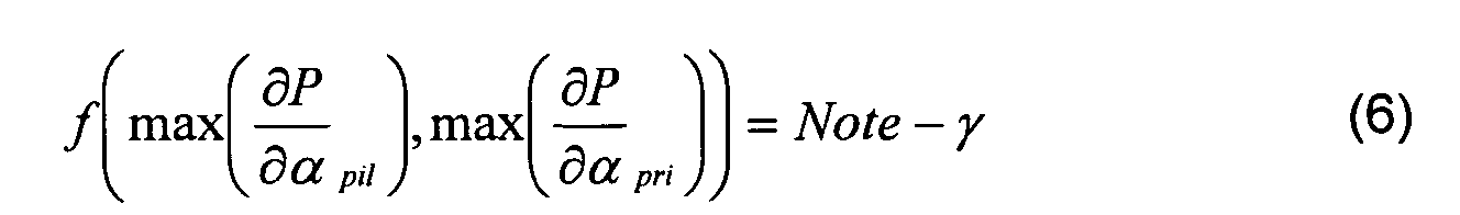
- the system is characterized in that the characteristic function of the predetermined allocation zone is determined as a function of an operating noise note of the engine depending on the pressure gradients corresponding to the pilot and main injection phases according to the relationship : where ⁇ and ⁇ are experimentally determined parameters.
- the system is characterized in that the means for determining the quantity of fuel injected into the cylinder during the pilot injection are adapted to sequentially determine the amount fuel injected into each cylinder independently of each other.
- the system is characterized in that it comprises control means adapted to control the supply means for calculating the quantity of fuel injected during the pilot injection into the cylinder so as to regulate in the cylinder the ratio value around a setpoint k to minimize engine operating noise.
- the amplitude of the noise of combustion of a particular motor vehicle diesel engine depends on the amplitude of the pressure gradient in the cylinder combustion chamber during ignition of the fuel.
- the amplitude of the pressure gradient is to it directly dependent on the initial conditions of inflammation. So in the case of a fuel-injected engine according to at least one pilot injection and a main injection, the pilot injection makes it possible to prepare favorable conditions for the main combustion. Therefore, the less the combustion chamber was prepared by a pilot injection at the beginning of ignition of the main fuel quantity plus the increase in the pressure is abrupt during this inflammation and therefore the more the noise of burning of the main is pronounced.
- the combustion noise depends both on the gradient of pressure during the pilot injection phase and the pressure gradient during the main injection phase. To minimize the noise of combustion, it is advisable then calculate pilot quantities injected into the cylinders of the engine that take into account the characteristics of the pressure gradient during these two phases.
- a combustion noise note of a cylinder can indeed be expressed by the relation: or by the relation: where ⁇ , ⁇ , a and are parameters determined during a listening campaign with a jury of experts, ⁇ P / ⁇ pil is the pressure gradient in the cylinder during the pilot injection phase of the cylinder cycle, ⁇ P / ⁇ pri is the pressure gradient in the cylinder during the main injection phase of the cylinder cycle, and ⁇ is the crankshaft angle of the cylinder considered.
- the ratio of the pressure gradients vary towards a different value k of 1 which is characteristic of the noise / emissions / robustness compromise calibration.
- the present invention proposes to calculate, for at least one operating point of the engine and a quantity of fuel injected during the predetermined main injection as a function of the operating point, a pilot quantity to be injected that is the solution to a problem. of minimization according to the equation where q pil is the quantity of fuel injected into the cylinder during the pilot injection, Q pil is the predetermined set of acceptable values of q pil , and k is a calibrated value close to 1.
- the pilot quantity, the combustion noise note according to relation (1), are determined for a particular cylinder and for an operating point given engine, that is, a given engine speed and load. For cover the operating range of the motor, it is possible to determine a pilot amount per cylinder for several operating points, like this is known from the state of the art. So solving the optimization problem is considered for a specific operating point and a cylinder.
- the allowable values of the pilot quantity are easily characterizable. Indeed, beyond a pilot quantity value injected q max / pil, the fuel consumption and the emission of pollutants become too important for a gain on negligible combustion noise see no if not a degradation of it. Similarly, it is known that below a certain value of pilot quantity injected q max / pil, it is certain that the noise of combustion is strongly degraded. So the set of allowable values for the pilot quantity can be simply characterized by the interval ⁇ q max / pil q max / pil ⁇ . Of course, nothing prevents to find the pilot quantity injected in the interval ⁇ 0 q max / pil ⁇ .
- the present invention does not use any engine model to solve the previous optimization problem, which has the other advantage that it is applicable to any engine regardless of the value of its characteristics mechanical and / or thermodynamic and therefore independently applicable variations in its characteristics.
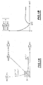
- thermodynamic model representative of the evolution of the value of the maximum of the pressure gradient in the cylinder during the main injection phase as a function of the value of the maximum of the pressure gradient during the pilot injection phase as represented by the curve of FIG. 1A representative of a thermodynamic model according to the relation: where h is the thermodynamic model representative of the evolution of the value of the maximum of the pressure gradient in the cylinder during the main injection phase as a function of the value of the maximum of the pressure gradient in the cylinder during the injection phase pilot.
- the shape of the curve shown is conventional and this curve can be parameterized by the pilot quantity q pil . Indeed, the injection of an increasing amount of pilot amount corresponds to a direction of travel of the curve according to the increasing values of the maximum of the pressure gradient during the pilot injection phase.
- thermodynamic model h It is not necessary to know explicitly this function nor the thermodynamic model h, looking for the optimal pilot injection quantity based only on qualitative considerations. For example, as it can be seen on the curve of Figure 1A, if the value of the ratio is higher at k, it is known that the pilot quantity injected is insufficient. The research of the optimal pilot quantity is then oriented towards larger pilot quantities. Similarly, if the value of the ratio is greater than k, we know that the quantity injected pilot is too important and the search is oriented accordingly to lower pilot quantities.
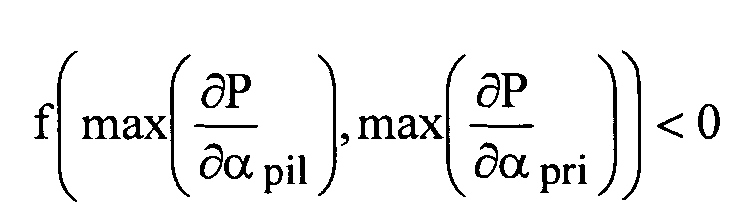
- relation (2) it is possible to add a feasibility constraint according to the relation: or is a characteristic function of a predetermined area of allocation of permissible values for the pair of values
- the values of these gradient maxima in a zone of values to ensure proper operation of the motor.
- the motor does not work properly and it is necessary to order it in a degraded mode.
- One way of characterizing the upper bounds of the allocation zone is to use the combustion noise note according to relation (1) where ⁇ and ⁇ are parameters determined experimentally during a listening campaign with a jury of experts and to choose for example a characteristic function of the allocation zone according to the relation: where ⁇ is a combustion noise threshold parameter determined during a listening campaign with a panel of experts.
- relations describing other characteristics of the engine as for example relations of fuel consumption, pollutant emission or other.
- combustion noise note according to the relationship (1) can be used in operation control systems of Classic diesel engines that are based on the use of combustion noise note.
- sampling may take into account linear and / or non-linear engine operation.
- FIG. 2 is a schematic view of an operation control system of a motor vehicle diesel engine according to the invention based on the previously described concepts.
- a diesel engine comprising means 12 for supplying fuel by multiple injections suitable for trigger a fuel injection into each cylinder according to at least one pilot injection and a main fuel injection.
- a diesel engine comprising means 12 for supplying fuel by multiple injections suitable for trigger a fuel injection into each cylinder according to at least one pilot injection and a main fuel injection.
- it may be a diesel engine with a common fuel rail cylinders by controlled injectors.
- the pilot quantity injected per cylinder and per operating point is provided by an information processing unit 14.
- This 16 command unit interrogates mapping means 18 of a storage unit 20 in according to the received speed and load information, receives in response the corresponding quantity of pilot quantity for each cylinder and sends it via an adder 22, to means 24 forming an injector mapping which deliver in response to the means 12 supply a set of information injection, relating in particular to the amount of pilot injection.
- the registration of the pilot quantities is activated by a unit 26 supervision of the information processing unit 14.
- This unit 26 of supervision sends a resetting request to the control unit 16 which starts then the determination of the optimal pilot quantity for each cylinder and for at least one operating point of the engine.
- the determination of the quantity pilot of the cylinders is then conducted sequentially, cylinder by cylinder independently of each other.
- Each cylinder is associated with a pressure sensor 28 for measuring the pressure in the cylinder's combustion chamber.
- This pressure sensor is conventionally known and can be incorporated into the combustion chamber or be non-intrusive.
- Means 30 for detecting the angle of the motor shaft are also provided. It may be for example a magnetic sensor Hall effect provided with a gear wheel associated with the motor shaft, as is known from the state of the art.
- the pressure sensors 28 and the motor shaft angle sensor 30 are connected to means 32 for determining the pressure gradients in the cylinders.
- These gradation determination means 32 are adapted to select a pressure signal coming from the pressure sensors as a function of a cylinder selection signal sent by the control unit 16 of the information processing unit 14 and to acquire a predefined portion of this selected pressure signal when the crankshaft angle of the selected cylinder is within an angle interval [ ⁇ d ⁇ f ]. This interval is delivered by the control unit 16, and ⁇ d is the acquisition start angle of the pressure signal and ⁇ f is the end of acquisition angle of the pressure signal.
- ⁇ d -30 ° and a value of ⁇ f equal to 40 ° correspond to an interval representative of the pilot injection phase and the main injection phase of the cycle of a cylinder. It is known that the pilot injection phase and the main injection phase take place in a crankshaft angle interval substantially equal to [-30 °, + 40 °].
- the means 32 for determining the pressure gradients are in further adapted to sample the selected pressure signal and derive digitally the sampled pressure signal so as to obtain a signal of sampled pressure gradient of the selected cylinder.
- the gradient pressure can be acquired analogically and then sampled.
- This pressure gradient signal is then supplied to a pilot quantity determination unit 34.
- This pilot quantity determination unit 34 comprises a calculation unit 36 which receives as input the pressure gradient and the measured crank angle to determine the maximum of the pressure gradient during the pilot injection phase and the maximum gradient during the main injection phase.
- this computing unit 36 receives as a second input the advance angle of the main injection ⁇ a of the control unit 16 and calculates the value of the maximum of the pressure gradient during the pilot injection phase ⁇ P / ⁇ pil as being the value of the maximum of the pressure gradient when the crank angle is less than ⁇ a , that is to say when this angle is in the interval [ ⁇ d ⁇ a ], and the maximum pressure gradient during the main injection phase ⁇ P / ⁇ pri as the maximum value of the pressure gradient when the crank angle is greater than or equal to ⁇ a, that is to say when this angle is in the range] ⁇ a ⁇ f ].
- the choice of the terminals is not an essential characteristic, the same results can be obtained with slightly different terminals.
- This unit also calculates, on the basis of these two maxima calculated, the ratio
- the values of the two gradient maxima of pressure as well as the value of the ratio are then provided to the control unit 16 to be stored in storage means 20 for further processing.
- the pilot quantity determination unit 34 also comprises an optimization unit 38 which receives the values of the gradient maxima of pressure and ratio, to determine an optimal value of pilot quantity. so that this value is not yet determined, this optimization unit 38 determines regularly a new pilot quantity value that is sent to the adder 22 to be added to the value from the means 18 forming mapping.
- This determination unit 34 requires certain parameters adjustment function of the operating point (speed, load) of the motor and possibly the selected cylinder. These setting parameters are read in a table 40 of the storage means means 20 by the unit 16 of command that sends them to the optimization unit 38. Operation and research an optimal pilot quantity will be described in more detail later.
- this value is provided to the control unit 16 which updates accordingly the means 18 forming cartography. Additional analysis of the results provided by unit 38 determination can be conducted to also update the parameters of the table 40 of parameters.
- FIG. 3 is an exemplary embodiment of the determination means pressure gradients in Figure 2.
- the determination means pressure gradients receive as input four pressure signals p1, p2, p3, p4 from the pressure sensors associated with the engine cylinders. These signals p1, p2, p3, p4 are supplied to controlled means 50 of signal selection adapted to select a pressure signal based of the cylinder selection signal c, delivered as described above by the control unit 16.
- These selection means 50 may for example comprise a controllable switch of conventional type.
- the means for determining the pressure gradients receive, as another input, the motor shaft angle signal ⁇ m which is supplied to a controllable adder 52 adapted to determine the crankshaft angle of the selected cylinder by the addition of a characteristic value of the selected cylinder, receiving as another input the cylinder selection signal c.
- the outputs of the selection means 50 and the adders 52 are connected to a windowing unit 54.
- This windowing unit also receives as inputs from the control unit 16 as explained above the two angle values ⁇ d and ⁇ f , respectively the acquisition start angle and the end angle of acquisition and selects the portion of the pressure signal corresponding to the crank angle included in the interval [ ⁇ d ⁇ a ].
- a digital converter / analog 55 samples this signal according to a predetermined crankshaft angle sampling period on the window determined by the selection means 50, for example 0.5 degree, to allow digital signal processing. It should be noted that sampling is not not necessarily constant. Indeed, it is possible to determine a law sample which finely samples the signal in the intervals where the signal has strong variations and samples the signal more in intervals where the signal varies little. In general, a sampling adaptive can be implemented as is known in the field of signal processing.
- the sampled signal is then supplied to a digital derivation filter 56, preferably a finite impulse response filter, which calculates a derivative digital signal of the sampled pressure signal.
- a digital derivation filter 56 preferably a finite impulse response filter, which calculates a derivative digital signal of the sampled pressure signal.
- FIG. 4 represents a flowchart of operation of pilot quantity determination means of Figure 2 and the manner in which these determining means calculate an optimal pilot quantity a cylinder, a particular operating point and a quantity of fuel injected during the predetermined main injection phase, the value of the pilot quantity injected into the other cylinders being set to a predetermined value, that stored in the means 18 forming mapping.
- the pilot amount q pil value injected at the input of the adder 22 by the optimization unit 38 is adjusted to a pre-determined initial value. If the determination is absolute, that is to say if the pilot quantity value sent from the mapping means 18 to the adder 22 is set to 0 when determining the pilot quantity, this initial value is included in FIG. the interval q max / pil. It may be for example the minimum value q min / pil or the value of the previously calculated setpoint for this cylinder.
- the initial value of q pil is set to value in the range ⁇ q min / pil - qp / pil qmax / pil - qp / pil ⁇ (it being understood that qp / pil is ⁇ q min / pil q max / pil ⁇ ) actually included in which is used as a search interval. It will be detailed thereafter a search for the absolute optimal pilot quantity for the sake of brevity of the description, without this being in any way restrictive.
- a test is carried out to know if the value of q pil is greater than q max / pil or less than q min / pil. If the result of this test is positive, an error message is generated and an engine malfunction status is diagnosed. If this result is negative, in a block 64, a cycle counter and two flags q + / pil and q - / pil are initialized to 1.
- a test is carried out to know whether the value of the cycle counter, adapted to count the cycles of the cylinder, is greater than or equal to a predetermined threshold value N + 1. If the result of this test is negative, in a block 68, the calculation unit 36 calculates and stores in the storage means 20, the maximum value of the pressure gradient ⁇ P / ⁇ pil during the pilot injection phase. and the maximum value of the pressure gradient ⁇ P / ⁇ pri during the main injection phase of the current cylinder cycle as well as the ratio of these two values.
- the cycle counter is incremented by one step an increment of one and then the output of block 68 is looped back to the input of block 66.
- a digital signal processing is then implemented by the calculation unit 36 in a block 70 on the last N values of ⁇ P / ⁇ pil of ⁇ P / ⁇ pri and of calculated.
- This digital processing may consist of noise filtering such as for example a calculation of average. It can also be estimation means using noise and / or motor models to obtain a more efficient filtering of the noise. However, calculating the average after saturation to limit the impact of very low or very high ratios corresponding to irregularities in the operation of the engine is preferred because it is robust numerically, very fast and does not use a model. Thus, as a result of this average calculation, three average values are obtained P 1 , P 2 and R corresponding respectively to the averages of the last N values of ⁇ P / ⁇ pil , ⁇ P / ⁇ pri and R.
- a first test on the value R is implemented to find out if the average value R is greater than or equal to a predetermined high ratio threshold value R_high. If the result of this test is positive, a test is implemented in a block 74 to know if the value of the flag q - / pil is equal to 0. If the result of this test on the value of q - / pil is positive, in a block 76, the pilot quantity q pil injected into the cylinder is increased by a predetermined pilot amount ⁇ q pil positive step increment, the value of the q + / pil flag is set to 0 then the block output 76 is looped back to the entrance of block 62.
- a second test on the value of R is implemented in a block 80 to know if the average value R is less than or equal to a predetermined low threshold value R_bas. If the result of this test is positive, a test is implemented in a block 82 to find out whether the value of q + / pil is equal to 0.
- a block 84 If the result of this test on the value of q + / pil is positive, in a block 84, the pilot quantity q pil injected into the cylinder is reduced by the pilot quantity increment step ⁇ q pil , the value of the flag q - / pil is set to 0 and the output of block 84 is looped back to the input of block 62.
- the interpolation of the block 78 consists in calculating by interpolation an optimum pilot quantity value when the access to the block 78 is made from the block 74 or the block 82. In fact, in these two cases, this means that one has traveled the range of acceptable values of q pil with a step that is too large, which exceeds (upwards or downwards) the optimal value without having reached it. If the access to block 78 is made from block 80, this means that a pilot quantity value has been determined which makes it possible to obtain a ratio of pressure gradient maxima close to one. In this case, a test is implemented to find out if the values P 1 , P 2 check the relation (4) of the optimization problem, ie if f ( P 1 , P 2) ⁇ 0. If the result of this test is positive then the maximum values of pressure gradient are acceptable for the operation of the engine. Otherwise, it means a malfunction of the engine which can therefore possibly switch to a degraded operating mode of the engine.
- the R_bas and R_haut values are determined to reflect the compromise noise / transmission / robustness as known in the field of engine combustion noise setting Both values frame the value k compromise set-noise / transmission set in the calibration . Their distance to this setpoint is a function of the sudden dispersion of the ratio and the robustness of the emissions and of the noise level at a small variation around this setpoint.
- the N value of the threshold for the cycle counter can be, for example chosen equal to 10, which is sufficient to satisfactorily filter the noise and the instantaneous variations of the characteristics of the combustion in the cylinder whose purpose is to determine the pilot quantity.
- this algorithm makes it possible to calculate a pilot quantity such that
- ⁇ q pil is chosen to satisfy the compromise of accuracy / search time as is commonly known in the field of optimization.
- thermodynamic model can be used, like a search by dichotomy or others. It is also possible to use an algorithm for identifying the parameters of the thermodynamic model according to relation (3) as a Kalman estimator, an estimator by maximum likelihood or other then calculate the optimal pilot amount problem of the corresponding optimization problem.
- control unit 16 can monitor continuously the value of the pressure gradient ratio and provide this value to the unit 26 of supervision.
- This supervision unit then implements a strategy of command that can for example consist of launching a new search of pilot quantity injected into the cylinders as soon as the value of the gradient ratio is not within a predetermined range of allowable values.
- the supervision unit 26 can also be adapted to trigger a resetting as soon as a time interval has elapsed since the last resetting, or as soon as a predetermined number of kilometers has been traveled since the last registration.
Abstract
Description
La présente invention concerne un système de contrôle du bruit de combustion d'un moteur Diesel de véhicule automobile.The present invention relates to a system for controlling the noise of combustion of a diesel engine of a motor vehicle.
Plus particulièrement, ce système concerne l'optimisation de consigne d'injection pour un moteur Diesel comportant des moyens d'alimentation en carburant , par exemple à rampe commune, du moteur sous forme d'injections multiples de carburant dans chaque cylindre de celui-ci pour minimiser le bruit de combustion.More particularly, this system relates to setpoint optimization injection system for a diesel engine comprising fuel supply means , for example with a common rail, of the motor in the form of multiple injections of fuel in each cylinder of it to minimize the noise of combustion.
Les défauts actuels de ce type de systèmes d'injection pour moteur Diesel sont d'une part une dispersion des caractéristiques du moteur en sortie d'usine, due par exemple aux tolérances de fabrication et aux pressions extrêmement élevées du système, et d'autre part une dérive dans le temps, au cours de l'utilisation du véhicule, de la caractéristique en débit des injecteurs. De plus, les caractéristiques du moteur lui-même évoluent au cours de sa vie, comme par exemple le taux de compression dans les cylindres, la perméabilité des soupapes ou des segments, ce qui modifie les conditions thermodynamiques de la combustion. La somme de ces dérives se traduit par une dégradation du bruit de combustion du moteur directement ressentie par l'utilisateur du véhicule.Current defects of this type of engine injection systems Diesel are on the one hand a dispersion of the characteristics of the engine output from manufacturing, for example because of manufacturing tolerances and extremely of the system, and secondly a drift in time, during the use of the vehicle, the characteristic in injectors flow. Moreover, the characteristics of the engine itself evolve during its life, as example the compression ratio in the cylinders, the permeability of the valves or segments, which modifies the thermodynamic conditions of combustion. The sum of these drifts results in a degradation of the combustion noise of the engine directly felt by the user of the vehicle.
On connaít déjà dans l'état de la technique, plusieurs systèmes visant
à recaler le système d'injection au cours de la vie du moteur de façon à assurer
que les quantités injectées correspondent à la valeur de consigne. Par exemple
le brevet EP 0 959 237 B1 présente une méthode de recalage du temps mort à
l'injection utilisant un accéléromètre. D'autres méthodes sont connues pour recaler
les débits pilotes en se basant sur le capteur de régime du moteur.Already known in the state of the art, several systems aiming at
to reset the injection system during the life of the engine to ensure
the quantities injected correspond to the set value. for
On connaít également des systèmes visant à modifier les quantités de carburant injectées dans les cylindres tenant compte de ces dérives pour corriger régulièrement la dégradation du bruit de combustion. Ces systèmes d'injection sont adaptés pour injecter du carburant dans les cylindres du moteur sous la forme d'au moins une injection pilote et une injection principale.Also known are systems aimed at modifying the quantities of fuel injected into the cylinders taking into account these drifts to correct regularly the degradation of the combustion noise. These injection systems are adapted to inject fuel into the engine cylinders under the at least one pilot injection and one main injection.
L'injection pilote sert à injecter une petite quantité de carburant quelques millisecondes avant l'injection principale de carburant, pour minimiser le bruit de combustion. En effet cette petite quantité de carburant conditionne favorablement les caractéristiques de l'inflammation de la quantité de carburant injectée lors de l'injection principale par une diminution des gradients de pression responsables du bruit de combustion. The pilot injection is used to inject a small amount of fuel a few milliseconds before the main fuel injection, to minimize the combustion noise. Indeed this small amount of fuel conditions favorably the characteristics of inflammation of the amount of fuel injected during the main injection by a decrease in the pressure gradients responsible combustion noise.
On connaít des systèmes de contrôle du fonctionnement d'un moteur Diesel mettant en oeuvre une commande de cette injection pilote. Ces systèmes proposent de modifier les quantités de carburant injectées lors de l'injection pilote pour minimiser le bruit de combustion en se basant sur le calcul d'une note de bruit de combustion connu sous le nom de « Système IEPC », pour « Index d'Energie de Pression de Combustion ». Toutefois de tels systèmes présentent plusieurs inconvénients car le calcul de la note de bruit utilise un modèle du moteur et de l'oreille humaine.There are known systems for controlling the operation of an engine Diesel implementing a command of this pilot injection. These systems propose to modify the quantities of fuel injected during the pilot injection to minimize combustion noise based on the calculation of a rating of combustion noise known as the "IEPC System", for "Index of Combustion Pressure Energy ". However, such systems present several disadvantages because the calculation of the noise note uses an engine model and the human ear.
Ceci suppose donc d'approximer le comportement réel du moteur par un modèle mathématique introduisant des erreurs. Pour réduire l'amplitude de telles erreurs, il est alors nécessaire d'augmenter la complexité du modèle ce qui a pour conséquences, non seulement une augmentation du temps de calcul, mais également une augmentation de la complexité du système lui-même, notamment en termes de taille de mémoire et de capacité de calcul du calculateur embarqué.This therefore involves approximating the actual behavior of the engine by a mathematical model introducing errors. To reduce the amplitude of such errors, then it is necessary to increase the complexity of the model which has consequences, not only an increase in the calculation time, but also an increase in the complexity of the system itself, in particular in terms of memory size and calculator computing capacity embedded.
De plus, de par la nature même du problème, le modèle de moteur utilisé peut devenir obsolète puisque les caractéristiques du moteur changent au cours du temps, impliquant que le modèle n'est plus représentatif au bout d'un certain temps, à moins de mettre régulièrement à jours ses paramètres, ce qui suppose là encore une augmentation du degré de complexité.Moreover, by the very nature of the problem, the engine model used can become obsolete as the engine characteristics change over time, implying that the model is no longer representative after a some time, unless you regularly update its settings, which Here again supposes an increase in the degree of complexity.
Ensuite, l'utilisation d'un modèle de l'oreille humaine implique le désavantage supplémentaire de supposer un modèle unique de comportement auditif pour tous les utilisateurs.Then, using a model of the human ear involves disadvantage additional to assume a unique pattern of auditory behavior for all users.
Cette approche nécessite un temps de calcul très important car elle nécessite un filtrage numérique complexe. De plus les valeurs obtenues sont très dispersées, ce qui impose de moyenner sur un nombre important de cycles avant d'obtenir une valeur utilisable pour le contrôle de l'injection.This approach requires a very important calculation time because it requires complex digital filtering. In addition, the values obtained are very dispersed, which requires averaging over a significant number of cycles before to obtain a usable value for the control of the injection.
Pour augmenter la fiabilité de la minimisation du bruit de combustion, une solution consiste alors à utiliser une autre note du bruit de combustion.To increase the reliability of minimizing the noise of combustion, one solution is then to use another note of the combustion noise.
A cet effet, la demande de brevet européen EP-A-1 209 458 concerne un procédé de détermination du bruit de combustion par l'utilisation de la méthode des ondelettes. Ce procédé s'affranchit certes de l'utilisation du modèle de l'oreille humaine et n'utilise pas directement lors du calcul de la note de bruit le modèle du moteur. Toutefois, cette méthode reste difficilement applicable de façon simple. En effet cette approche reste une approche basée sur un modèle mathématique de moteur, ne serait ce que pour le choix de la base des fonctions, et est par conséquent sujette aux mêmes inconvénients liés à l'utilisation d'un modèle. Enfin, cette approche reste coûteuse en temps de calcul car elle nécessite plusieurs filtrages numériques successifs pour obtenir les informations utiles pour le contrôle de l'injection. De plus, la dispersion coup à coup des valeurs est encore plus importante que pour la méthode « IEPC ».For this purpose, the European patent application EP-A-1 209 458 relates to a method of determining combustion noise by using the method wavelets. This method certainly avoids the use of the model of the human ear and does not use directly when calculating the noise note the engine model. However, this method remains difficult to apply simple. Indeed, this approach remains a model-based approach mathematical engine, if only for the choice of the base functions, and is therefore subject to the same disadvantages of using a model. Finally, this approach remains expensive in computing time because it requires several successive digital filtering to obtain useful information for the control of the injection. Moreover, the sudden dispersion of the values is even more important than for the "IEPC" method.
Le but de la présente invention est de résoudre les problèmes susmentionnés en proposant notamment une approche non basée sur un modèle, efficace pour minimiser le bruit de combustion, applicable simplement et très peu coûteuse en terme de complexité et de temps de calcul.The object of the present invention is to solve the aforementioned problems by proposing a non-model based approach, effective in minimizing combustion noise, applicable simply and very little costly in terms of complexity and calculation time.
A cet effet, l'invention a pour objet un système de contrôle du bruit de combustion d'un moteur Diesel de véhicule automobile, du type comportant des moyens d'alimentation en carburant du moteur par injections multiples de carburant dans chaque cylindre de celui-ci, adaptés pour déclencher une alimentation en carburant de chaque cylindre selon au moins une injection pilote et une injection principale de carburant, caractérisé en ce qu'il comprend :
- des moyens de détermination des gradients de pression dans le cylindre du moteur lors de son fonctionnement au moins lors des phases à injection pilote et principale ;
- des moyens de détermination de la quantité de carburant injectée dans le cylindre lors de l'injection pilote adaptés pour une quantité prédéterminée de carburant lors de l'injection principale afin d'optimiser un critère de fonctionnement du cylindre basé sur le rapport entre les gradients de pression correspondants aux phases à injection pilote et principale, et donc d'optimiser le bruit de fonctionnement du moteur.
- means for determining the pressure gradients in the engine cylinder during its operation at least during the pilot and main injection phases;
- means for determining the quantity of fuel injected into the cylinder during the pilot injection adapted for a predetermined quantity of fuel during the main injection in order to optimize a criterion of operation of the cylinder based on the ratio between the gradients of pressure corresponding to the pilot and main injection phases, and thus to optimize the operating sound of the engine.
Selon une autre caractéristique, le système est caractérisé en ce que
les moyens de détermination de la quantité de carburant injectée dans le cylindre
lors de l'injection pilote sont adaptés pour déterminer, par la mise en oeuvre d'un
algorithme d'optimisation, une quantité de carburant injectée par cylindre lors de
l'injection pilote selon les relations :


Selon une autre caractéristique, le système est caractérisé en ce que les moyens de détermination de la quantité de carburant injectée dans le cylindre lors de l'injection pilote sont adaptés pour mettre en oeuvre un algorithme d'optimisation qui comprend:
- une étape d'acquisition d'au moins un signal de gradient de pression représentatif de l'évolution du gradient de pression lors d'un cycle du cylindre.
- une étape de calcul d'une valeur R représentative du ratio
pour le cylindre et la quantité constante de carburant injectée considérés en fonction du au moins un signal de gradient de pression acquis ; et

- une étape de détermination d'une variation de la quantité de carburant
injectée dans le cylindre lors de la phase pilote en fonction de la valeur
R calculée, selon une loi de parcours prédéterminée de l'ensemble prédéterminé de valeurs admissibles de quantité de carburant injectée lors de l'injection pilote.
- a step of acquiring at least one pressure gradient signal representative of the evolution of the pressure gradient during a cycle of the cylinder.
- a step of calculating an R value representative of the ratio for the cylinder and the constant amount of injected fuel considered as a function of the at least one acquired pressure gradient signal; and
- a step of determining a variation of the quantity of fuel injected into the cylinder during the pilot phase as a function of the value
R calculated according to a predetermined path law of the predetermined set of allowable values of quantity of fuel injected during the pilot injection.
Selon une autre caractéristique, le système est caractérisé en ce que
la loi de parcours de l'ensemble prédéterminé de valeurs admissibles de quantité
de carburant injectée lors de l'injection pilote, est déterminée par les caractéristiques
d'un modèle thermodynamique selon la relation :
Selon une autre caractéristique, le système est caractérisé en ce qu'il comprend un capteur de pression associé à chaque cylindre raccordé aux moyens de détermination des gradients de pression.According to another characteristic, the system is characterized in that comprises a pressure sensor associated with each cylinder connected to the means for determining the pressure gradients.
Selon une autre caractéristique, le système est caractérisé en ce qu'il comprend des moyens d'acquisition de l'angle de l'arbre moteur raccordé aux moyens de détermination des gradients de pression.According to another characteristic, the system is characterized in that comprises means for acquiring the angle of the motor shaft connected to the means for determining the pressure gradients.
Selon une autre caractéristique, le système est caractérisé en ce les moyens de détermination des gradients de pression comprennent :
- des moyens de sélection de signal pour sélectionner un signal de pression d'un cylindre sélectionné parmi la pluralité des signaux de pression des cylindres;
- des moyens de fenêtrage d'acquisition pour acquérir le signal de pression du cylindre sélectionné délivré par le capteur de pression associé lorsque l'angle vilebrequin du cylindre est compris dans une plage d'angle vilebrequin d'acquisition prédéterminée représentative de la phase à injection pilote et de la phase à injection principale du cycle du cylindre;
- un convertisseur analogique-numérique pour échantillonner le signal de pression en sortie des moyens de fenêtrage selon une loi d'échantillonnage prédéterminée ; et
- un filtre numérique adapté pour déterminer une dérivée numérique du signal de pression échantillonné et ainsi obtenir le signal de gradient de pression de cylindre.
- signal selection means for selecting a pressure signal of a selected one of the plurality of cylinder pressure signals;
- acquisition fenestration means for acquiring the selected cylinder pressure signal delivered by the associated pressure sensor when the crankshaft angle of the cylinder is within a predetermined acquisition crankshaft angle range representative of the pilot injection phase and the main injection phase of the cylinder cycle;
- an analog-to-digital converter for sampling the output pressure signal from the windowing means according to a predetermined sampling law; and
- a digital filter adapted to determine a digital derivative of the sampled pressure signal and thereby obtain the cylinder pressure gradient signal.
Selon une autre caractéristique, le système est caractérisé en ce que le filtre numérique de dérivation est un filtre numérique à réponse impulsionnelle finie.According to another characteristic, the system is characterized in that the digital bypass filter is a digital impulse response filter over.
Selon une autre caractéristique, le système est caractérisé en ce que
les moyens de détermination comprennent des moyens de calcul adaptés pour
calculer et stocker, à chaque cycle du cylindre, la valeur

Selon une autre caractéristique, le système est caractérisé en ce que
la fonction caractéristique de la zone prédéterminée d'allocation est déterminée
en fonction d'une note de bruit de fonctionnement du moteur dépendant des gradients
de pression correspondant aux phases à injections pilote et principale selon
la relation :

Selon une autre caractéristique, le système est caractérisé en ce que les moyens de détermination de la quantité de carburant injectée dans le cylindre lors de l'injection pilote sont adaptés pour déterminer séquentiellement la quantité de carburant injectée dans chaque cylindre indépendamment les uns des autres.According to another characteristic, the system is characterized in that the means for determining the quantity of fuel injected into the cylinder during the pilot injection are adapted to sequentially determine the amount fuel injected into each cylinder independently of each other.
Selon une autre caractéristique, le système est caractérisé en ce qu'il
comprend des moyens de commande adaptés pour commander les moyens
d'alimentation pour calculer la quantité de carburant injectée lors de l'injection
pilote dans le cylindre de manière à réguler dans le cylindre la valeur du ratio

La présente invention sera mieux comprise à la lecture de la description qui va suivre, donnée uniquement à titre d'exemple et faite en se référant aux dessins annexés, où des références identiques identifient des éléments identiques, et dans lesquels :
- la figure 1A est une courbe représentative des valeurs du maximum du gradient de pression lors de la phase à injection principale en fonction des valeurs du maximum du gradient de pression lors de la phase à injection pilote, dans un cylindre du moteur ;
- la figure 1 B est une courbe représentative d'un critère à minimiser dépendant du ratio des valeurs maximales de gradient de pression en fonction de la quantité pilote injectée ;
- la figure 2 est une vue schématique d'un mode de réalisation d'un système de contrôle du fonctionnement d'un moteur Diesel de véhicule automobile selon l'invention ;
- la figure 3 est une vue schématique de moyens de détermination des gradient de pression de la figure 2 et entrant dans la constitution d'un système selon l'invention ;
- la figure 4 est un organigramme de l'algorithme de recherche de la valeur de la quantité pilote optimale mis en oeuvre dans le système selon l'invention.
- FIG. 1A is a curve representing the values of the maximum of the pressure gradient during the main injection phase as a function of the values of the maximum of the pressure gradient during the pilot injection phase, in a cylinder of the engine;
- FIG. 1B is a curve representative of a criterion to be minimized depending on the ratio of the maximum values of the pressure gradient as a function of the pilot quantity injected;
- FIG. 2 is a schematic view of an embodiment of a system for controlling the operation of a motor vehicle diesel engine according to the invention;
- Figure 3 is a schematic view of the pressure gradient determination means of Figure 2 and forming part of a system according to the invention;
- FIG. 4 is a flowchart of the algorithm for finding the value of the optimal pilot quantity implemented in the system according to the invention.
Comme il a déjà été indiqué précédemment, l'amplitude du bruit de combustion d'un moteur notamment Diesel de véhicule automobile dépend de l'amplitude du gradient de pression dans la chambre de combustion des cylindres lors de l'inflammation du carburant. L'amplitude du gradient de pression est quant à elle directement dépendantes des conditions initiales de l'inflammation. Ainsi dans le cas d'un moteur alimenté en carburant en injection selon au moins une injection pilote et une injection principale, l'injection pilote permet de préparer des conditions favorables à la combustion principale. Par conséquent, moins la chambre de combustion a été préparée par une injection pilote au début de l'inflammation de la quantité de carburant principale, plus l'augmentation de la pression est brusque lors de cette inflammation et par conséquent plus le bruit de combustion de la principale est prononcé.As already indicated above, the amplitude of the noise of combustion of a particular motor vehicle diesel engine depends on the amplitude of the pressure gradient in the cylinder combustion chamber during ignition of the fuel. The amplitude of the pressure gradient is to it directly dependent on the initial conditions of inflammation. So in the case of a fuel-injected engine according to at least one pilot injection and a main injection, the pilot injection makes it possible to prepare favorable conditions for the main combustion. Therefore, the less the combustion chamber was prepared by a pilot injection at the beginning of ignition of the main fuel quantity plus the increase in the pressure is abrupt during this inflammation and therefore the more the noise of burning of the main is pronounced.
C'est pourquoi, le bruit de combustion dépend à la fois du gradient de pression lors de la phase à injection pilote et du gradient de pression lors de la phase à injection principale. Pour minimiser le bruit de combustion, il convient alors de calculer des quantités pilote injectées dans les cylindres du moteur qui tiennent compte des caractéristiques du gradient de pression lors de ces deux phases.Therefore, the combustion noise depends both on the gradient of pressure during the pilot injection phase and the pressure gradient during the main injection phase. To minimize the noise of combustion, it is advisable then calculate pilot quantities injected into the cylinders of the engine that take into account the characteristics of the pressure gradient during these two phases.
Augmenter la quantité pilote de carburant diminue l'amplitude du gradient de pression lors de l'inflammation de la quantité de carburant principale. Si la quantité de carburant pilote injectée dans un cylindre est telle que le maximum du gradient de pression lors de la phase à injection pilote est sensiblement égal au maximum du gradient de pression lors de la phase à injection principale, le bruit de combustion dans ce cylindre est alors minimal.Increase the pilot amount of fuel decreases the gradient amplitude pressure during ignition of the main fuel quantity. Yes the amount of pilot fuel injected into a cylinder is such that the maximum of the pressure gradient during the pilot injection phase is substantially equal at the maximum of the pressure gradient during the main injection phase, the The combustion noise in this cylinder is then minimal.
Une note de bruit de combustion d'un cylindre peut en effet être exprimée
par la relation :


![]()
![]()
La corrélation de ces notes de bruit de combustion avec une note de bruit délivrée par le jury d'experts est très élevée et cela quelque soit le point de fonctionnement du moteur considéré. Ainsi, comme on peut le constater en considérant la note de bruit selon la relation (1a) ci-dessus, pour minimiser le bruit de fonctionnement du moteur, ou de manière équivalente pour maximiser cette note de bruit de combustion selon la relation (1 a) ci-dessus, il faut et il suffit de faire tendre le ratio des gradients de pression apparaissant dans le terme logarithmique vers 1 et cela indépendamment du point de fonctionnement du moteur, du cylindre considéré et des valeurs des paramètres mécaniques et/ou thermodynamiques du moteur. De façon à assurer un niveau d'émission de polluants acceptable et une bonne robustesse, notamment par rapport à la dispersion coup à coup de l'injection pilote, il est particulièrement avantageux de faire tendre le ratio des gradients de pression vers une valeur k différente de 1 qui est caractéristique de la calibration du compromis bruit / émissions / robustesse.The correlation of these notes of combustion noise with a noise note delivered by the jury of experts is very high and this whatever the point of operation of the engine considered. Thus, as can be seen by considering the noise note according to the relation (1a) above, to minimize the noise of operation of the engine, or equivalently to maximize this note of combustion noise according to the relationship (1a). ) above, it is necessary and sufficient to make the ratio of the pressure gradients appearing in the logarithmic term towards 1, and this independently of the operating point of the engine, the cylinder considered and the values of the mechanical and / or thermodynamic parameters of the engine. In order to ensure an acceptable pollutant emission level and a good robustness, particularly with respect to the sudden dispersion of the pilot injection, it is particularly advantageous to make the ratio of the pressure gradients vary towards a different value k of 1 which is characteristic of the noise / emissions / robustness compromise calibration.
Ainsi la présente invention se propose de calculer, pour au moins un
point de fonctionnement du moteur et une quantité de carburant injectée lors de
l'injection principale prédéterminée en fonction du point de fonctionnement, une
quantité pilote à injecter qui soit la solution à un problème de minimisation selon
l'équation
La quantité pilote, la note de bruit de combustion selon la relation (1), sont déterminées pour un cylindre particulier et pour un point de fonctionnement du moteur donné, c'est-à-dire un régime et une charge du moteur donnés. Pour couvrir la plage de fonctionnement du moteur, il est possible de déterminer une quantité pilote par cylindre pour plusieurs points de fonctionnement, comme cela est connu de l'état de la technique. Ainsi la résolution du problème d'optimisation est considéré pour un point de fonctionnement déterminé et un cylindre.The pilot quantity, the combustion noise note according to relation (1), are determined for a particular cylinder and for an operating point given engine, that is, a given engine speed and load. For cover the operating range of the motor, it is possible to determine a pilot amount per cylinder for several operating points, like this is known from the state of the art. So solving the optimization problem is considered for a specific operating point and a cylinder.
Les valeurs admissibles de la quantité pilote sont aisément caractérisables. En effet, au-delà d'une valeur de quantité pilote injectée q max / pil, la consommation de carburant et l'émission de polluants deviennent trop importantes pour un gain sur le bruit de combustion négligeable voir nul si ce n'est une dégradation de celui-ci. De même, il est connu qu'en dessous d'une certaine valeur de quantité pilote injectée q max / pil, il est certain que le bruit de combustion est fortement dégradé. Ainsi l'ensemble des valeurs admissibles pour la quantité pilote peut être simplement caractérisé par l'intervalle └q max / pil q max / pil┘. Bien entendu, rien n'empêche de rechercher la quantité pilote injectée dans l'intervalle └0 q max / pil┘.The allowable values of the pilot quantity are easily characterizable. Indeed, beyond a pilot quantity value injected q max / pil, the fuel consumption and the emission of pollutants become too important for a gain on negligible combustion noise see no if not a degradation of it. Similarly, it is known that below a certain value of pilot quantity injected q max / pil, it is certain that the noise of combustion is strongly degraded. So the set of allowable values for the pilot quantity can be simply characterized by the interval └q max / pil q max / pil┘. Of course, nothing prevents to find the pilot quantity injected in the interval └0 q max / pil┘.
Outre le fait de calculer une quantité pilote minimisant le bruit de combustion par l'utilisation d'un critère ne faisant intervenir aucun modèle de l'oreille humaine, la présente invention n'utilise aucun modèle du moteur pour résoudre le problème d'optimisation précédent, ce qui a pour autre avantage qu'elle est applicable à un moteur quelconque indépendamment de la valeur de ses caractéristiques mécaniques et/ou thermodynamiques et donc applicable indépendamment des variations de ses caractéristiques.In addition to calculating a pilot quantity that minimizes combustion noise by the use of a criterion involving no model of the ear human, the present invention does not use any engine model to solve the previous optimization problem, which has the other advantage that it is applicable to any engine regardless of the value of its characteristics mechanical and / or thermodynamic and therefore independently applicable variations in its characteristics.
Un autre avantage non négligeable du problème d'optimisation selon
la relation (2) est que le critère que l'on cherche à minimiser, à savoir le critère
Il est possible de le comprendre en considérant l'évolution du maximum
du gradient de pression dans un cylindre lors de la phase à injection principale
en fonction de la valeur du maximum du gradient de pression lors de la
phase à injection pilote comme cela est représenté par la courbe de la figure 1A
représentative d'un modèle thermodynamique selon la relation :

L'allure de la courbe représentée est classique et cette courbe peut être paramétrée par la quantité pilote qpil. En effet, l'injection d'une quantité croissante de quantité pilote correspond à un sens de parcours de la courbe selon les valeurs croissantes du maximum du gradient de pression lors de la phase à injection pilote.The shape of the curve shown is conventional and this curve can be parameterized by the pilot quantity q pil . Indeed, the injection of an increasing amount of pilot amount corresponds to a direction of travel of the curve according to the increasing values of the maximum of the pressure gradient during the pilot injection phase.
A partir de ces caractéristiques, il est possible d'en déduire simplement
la courbe caractéristique de la quantité
Il n'est pas nécessaire de connaítre explicitement cette fonction ni le modèle thermodynamique h, la recherche de la quantité d'injection pilote optimale ne se basant que sur des considérations qualitatives. Par exemple, comme on peut le constater sur la courbe de la figure 1A, si la valeur du ratio est supérieure à k, on sait que la quantité pilote injectée est insuffisante. La recherche de la quantité pilote optimale s'oriente alors donc vers des quantités pilotes plus importantes. De même si la valeur du ratio est supérieure à k, on sait que la quantité pilote injectée est trop importante et la recherche s'oriente en conséquence vers des quantités pilotes plus faibles.It is not necessary to know explicitly this function nor the thermodynamic model h, looking for the optimal pilot injection quantity based only on qualitative considerations. For example, as it can be seen on the curve of Figure 1A, if the value of the ratio is higher at k, it is known that the pilot quantity injected is insufficient. The research of the optimal pilot quantity is then oriented towards larger pilot quantities. Similarly, if the value of the ratio is greater than k, we know that the quantity injected pilot is too important and the search is oriented accordingly to lower pilot quantities.
A la relation (2) il est possible d'ajouter une contrainte de faisabilité selon
la relation :

En effet, il est souhaitable que les valeurs de ces maxima de gradient de pression soient dans une zone de valeurs pour assurer un bon fonctionnement du moteur. Par exemple, dans le cas où les gradients sont inférieurs à des valeurs calibrables de seuil bas de gradient, le moteur ne fonctionne pas correctement et il est nécessaire de le commander dans un mode dégradé.Indeed, it is desirable that the values of these gradient maxima in a zone of values to ensure proper operation of the motor. For example, in the case where the gradients are lower than calibrated values of low gradient threshold, the motor does not work properly and it is necessary to order it in a degraded mode.
Il est également possible d'imaginer un ratio égal à k, tout en ayant des valeurs maximales de gradient de pression lors des phases à injection pilote et principale supérieures à des valeurs de seuil haut de gradient très importantes, ce qui signifie également un dysfonctionnement du moteur. It is also possible to imagine a ratio equal to k, while having maximum pressure gradient values during pilot injection phases and main higher than very high threshold values of gradient, which also means engine malfunction.
Une manière de caractériser les bornes supérieures de la zone
d'allocation, c'est-à-dire les valeurs de seuil haut de gradient, est d'utiliser la note
de bruit de combustion selon la relation (1)
A ces relations, il est également possible de rajouter des relations décrivant d'autres caractéristiques du moteur comme par exemple des relations de consommation de carburant, d'émission de polluants ou autres.To these relations, it is also possible to add relations describing other characteristics of the engine as for example relations of fuel consumption, pollutant emission or other.
Il est à noter que l'exemple de note de bruit de combustion selon la relation (1) peut être utilisé dans des systèmes de contrôle de fonctionnement de moteur Diesel classiques qui sont basés sur l'utilisation de note de bruit de combustion.It should be noted that the example of combustion noise note according to the relationship (1) can be used in operation control systems of Classic diesel engines that are based on the use of combustion noise note.
Un exemple de zone d'allocation est donné par la zone hachurée ZA de la figure 1A. L'infaisabilité du problème d'optimisation selon les relations (2) et (4) permet donc de diagnostiquer un état dégradé du moteur et plus particulièrement un problème de dérive du moteur.An example of an allocation zone is given by the shaded area ZA of Figure 1A. The infeasibility of the problem of optimization according to the relations (2) and (4) thus makes it possible to diagnose a deteriorated state of the engine and more particularly a problem of engine drift.
Grâce à la résolution du problème d'optimisation qui vient d'être décrite, il est possible de calculer simplement la quantité pilote pour un cylindre et pour un point de fonctionnement déterminé. Il est alors possible de concevoir un système de contrôle du fonctionnement du moteur Diesel ayant pour principal objet de minimiser le bruit de combustion des cylindres. En effet en sélectionnant un nombre de points de fonctionnement (Régime, Charge) du moteur et en déterminant régulièrement pour chaque cylindre et pour chacun de ces points une quantité pilote optimale, le bruit de fonctionnement est ainsi minimisé sur l'ensemble de la plage de fonctionnement. Thanks to the resolution of the optimization problem that has just been described, it is possible to simply calculate the pilot quantity for a cylinder and for a specific operating point. It is then possible to conceive a Diesel engine operation control system having as principal object to minimize the combustion noise of the cylinders. Indeed by selecting number of operating points (engine speed, load) and determining regularly for each cylinder and for each of these points a optimal pilot quantity, the operating noise is thus minimized on the entire operating range.
Le choix des points de fonctionnement est réalisé de manière classique et connu en soi par échantillonnage de la plage de fonctionnement. Cet échantillonnage peut par exemple tenir compte des zone linéaires et/ou non linéaires du fonctionnement du moteur.The choice of operating points is made in a conventional manner and known per se by sampling the operating range. This For example, sampling may take into account linear and / or non-linear engine operation.
La simplicité et la rapidité de la détermination de la quantité pilote solution du problème d'optimisation permet d'envisager un recalage fréquent des quantités pilotes et ainsi d'obtenir une régulation du bruit de fonctionnement autour de sa valeur minimale sur l'ensemble de la plage de fonctionnement, comme cela est décrit par la suite.Simplicity and speed of determination of the quantity pilot solution optimization problem makes it possible to envisage a frequent registration of pilot quantities and thus to get a regulation of the operating noise around of its minimum value over the entire operating range, as this is described later.
Il est à noter qu'il est équivalent, pour un cylindre, de :

Ainsi dans la suite de la présente description, il est fait mention de manière équivalente à l'une ou l'autre de ces assertions.Thus in the remainder of the present description, reference is made to equivalent to one or other of these assertions.
La figure 2 est une vue schématique d'un système de contrôle du fonctionnement d'un moteur Diesel de véhicule automobile selon l'invention basé sur les concepts précédemment décrits.FIG. 2 is a schematic view of an operation control system of a motor vehicle diesel engine according to the invention based on the previously described concepts.
On a représenté sous la référence 10, un moteur Diesel, comportant
des moyens 12 d'alimentation en carburant par injections multiples adaptés pour
déclencher une injection de carburant dans chaque cylindre selon au moins une
injection pilote et une injection principale de carburant. Par exemple il peut s'agir
d'un moteur Diesel pourvu d'une rampe commune d'alimentation en carburant
des cylindres par des injecteurs commandés.Is represented under the
Entre deux instants de recalage des quantités pilotes, la quantité pilote
injectée par cylindre et par point de fonctionnement (Régime, charge) du moteur
est fournie par une unité 14 de traitement d'informations. Celle-ci comprend une
unité 16 de commande qui reçoit en entrée des informations sur le régime et la
charge du moteur Diesel 10 de façon classique. Cette unité 16 de commande
interroge des moyens formant cartographie 18 d'une unité de stockage 20 en
fonction des informations de régime et de charge reçues, reçoit en réponse la
consigne correspondante de quantité pilote pour chaque cylindre et l'envoie, via
un additionneur 22, à des moyens 24 formant cartographie d'injecteur qui délivrent
en réponse aux moyens 12 d'alimentation une information de consigne
d'injection, relative notamment à la quantité d'injection pilote.Between two instants of registration of the pilot quantities, the pilot quantity
injected per cylinder and per operating point (engine speed, load)
is provided by an
Pour des raisons de concision, il n'a pas été représenté les différents moyens commandant les quantités de carburant injectées lors de l'injection principale. Comme il est connu du domaine de la commande d'injection pour moteur Diesel, ces quantités sont elles aussi dépendantes du point de fonctionnement et sont déterminées en fonction de celui-ci.For the sake of brevity, it was not represented the different means controlling the quantities of fuel injected during the main injection. As is known from the field of engine injection control Diesel, these quantities are also dependent on the point of operation and are determined according to it.
Régulièrement le recalage des quantités pilotes est activé par une unité
26 de supervision de l'unité 14 de traitement d'informations. Cette unité 26 de
supervision envoie une requête de recalage à l'unité 16 de commande qui lance
alors la détermination de la quantité pilote optimale pour chaque cylindre et pour
au moins un point de fonctionnement du moteur. La détermination de la quantité
pilote des cylindres est alors menée de façon séquentielle, cylindre par cylindre
indépendamment les uns des autres.Regularly the registration of the pilot quantities is activated by a
Chaque cylindre est associé à un capteur 28 de pression pour mesurer
la pression dans la chambre de combustion du cylindre. Ce capteur de pression
est classiquement connu et peut être incorporé dans la chambre de combustion
ou être non intrusif.Each cylinder is associated with a
Des moyens 30 de détection de l'angle de l'arbre moteur sont également prévus. Il peut s'agir par exemple d'un capteur magnétique à effet Hall pourvu d'une roue dentée associé à l'arbre moteur, comme cela est connu de l'état de la technique.Means 30 for detecting the angle of the motor shaft are also provided. It may be for example a magnetic sensor Hall effect provided with a gear wheel associated with the motor shaft, as is known from the state of the art.
A partir des mesures d'angle délivrées par le capteur d'angle, il est possible d'en déduire simplement l'angle vilebrequin de chaque cylindre.From the angle measurements delivered by the angle sensor, it is it is possible to deduce simply the crankshaft angle of each cylinder.
Les capteurs 28 de pression et le capteur 30 d'angle d'arbre moteur
sont raccordés à des moyens 32 de détermination des gradients de pression
dans les cylindres. Ces moyens 32 de détermination des gradients sont adaptés
pour sélectionner un signal de pression en provenance des capteurs de pression
en fonction d'un signal de sélection de cylindre envoyé par l'unité 16 de commande
de l'unité 14 de traitement d'informations et pour acquérir une portion
prédéfinie de ce signal de pression sélectionné lorsque l'angle vilebrequin du cylindre
sélectionné est compris dans un intervalle d'angle [αd αf]. Cet intervalle
est délivré par l'unité 16 de commande, et αd est l'angle de début d'acquisition
du signal de pression et αf est l'angle de fin d'acquisition du signal de pression.The
De façon typique une valeur de αd égale à -30° et une valeur de αf égale à 40° correspondent à un intervalle représentatif de la phase à injection pilote et de la phase à injection principale du cycle d'un cylindre. Il est en effet connu que la phase à injection pilote et la phase à injection principale ont lieu dans un intervalle d'angle vilebrequin sensiblement égal à [-30°, +40°].Typically a value of α d equal to -30 ° and a value of α f equal to 40 ° correspond to an interval representative of the pilot injection phase and the main injection phase of the cycle of a cylinder. It is known that the pilot injection phase and the main injection phase take place in a crankshaft angle interval substantially equal to [-30 °, + 40 °].
Les moyens 32 de détermination des gradients de pression sont en outre adaptés pour échantillonner le signal de pression sélectionné et dériver numériquement le signal de pression échantillonné pour ainsi obtenir un signal de gradient de pression échantillonné du cylindre sélectionné. Bien entendu, le gradient de pression peut être acquis de façon analogique puis être échantillonné.The means 32 for determining the pressure gradients are in further adapted to sample the selected pressure signal and derive digitally the sampled pressure signal so as to obtain a signal of sampled pressure gradient of the selected cylinder. Of course, the gradient pressure can be acquired analogically and then sampled.
Ce signal de gradient de pression est alors fourni à une unité 34 de
détermination de quantité pilote. Cette unité 34 de détermination de quantité pilote
comprend une unité 36 de calcul qui reçoit en entrée le gradient de pression
et l'angle vilebrequin mesuré pour déterminer le maximum du gradient de pression
lors de la phase à injection pilote et le maximum de gradient lors de la phase
à injection principale. Pour cela, cette unité 36 de calcul reçoit comme seconde
entrée l'angle d'avance de l'injection principale αa de l'unité 16 de commande et
calcule la valeur du maximum du gradient de pression lors de la phase à injection
pilote ∂P / ∂αpil comme étant la valeur du maximum du gradient de pression lorsque
l'angle vilebrequin est inférieur à αa , c'est-à-dire quand cet angle est compris
dans l'intervalle [αd αa], et le maximum du gradient de pression lors de la phase
à injection principale ∂P / ∂αpri comme étant la valeur maximum du gradient de pression
lorsque l'angle vilebrequin est supérieur ou égal à αa , c'est-à-dire lorsque
cet angle est compris dans l'intervalle ]αa αf]. Il est à noter que le choix des
bornes n'est pas une caractéristique essentielle, les mêmes résultats pouvant
être obtenus avec des bornes légèrement différentes. This pressure gradient signal is then supplied to a pilot
Cette unité calcule également, sur la base des ces deux maxima calculés,
le ratio
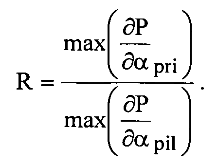
Les valeurs des deux maxima de gradient de
pression ainsi que la valeur du ratio sont alors fournies à l'unité 16 de commande
pour être stockées dans des moyens de stockage 20 pour un traitement ultérieur.The values of the two gradient maxima of
pressure as well as the value of the ratio are then provided to the
L'unité 34 de détermination de quantité pilote comprend par ailleurs
une unité 38 d'optimisation qui reçoit les valeurs des maxima de gradient de
pression et de ratio, pour déterminer une valeur optimale de quantité pilote. Tant
que cette valeur n'est pas encore déterminée, cette unité 38 d'optimisation détermine
régulièrement une nouvelle valeur de quantité pilote qui est envoyée à
l'additionneur 22 pour être additionnée à la valeur provenant des moyens 18 formant
cartographie. Cette unité 34 de détermination nécessite certains paramètres
de réglage fonction du point de fonctionnement (régime, charge) du moteur
et éventuellement du cylindre sélectionné. Ces paramètres de réglage sont lus
dans une table 40 de paramètres des moyens 20 de stockage par l'unité 16 de
commande qui les envoie à l'unité 38 d'optimisation. Le fonctionnement et la recherche
d'une quantité pilote optimale sera décrite plus en détail par la suite.The pilot
Une fois la valeur de la quantité pilote optimale déterminée, cette valeur
est fournie à l'unité 16 de commande qui met à jour en conséquence les
moyens 18 formant cartographie. Une analyse supplémentaire des résultats fournis
par l'unité 38 de détermination peut être menée pour également mettre à jour
les paramètres de la table 40 de paramètres.Once the value of the optimal pilot quantity has been determined, this value
is provided to the
La figure 3 est un exemple de mode de réalisation des moyens de détermination
des gradients de pression de la figure 2. En supposant que le moteur
Diesel 10 comprend par exemple quatre cylindres, les moyens de détermination
des gradients de pression reçoivent en entrée quatre signaux de pression p1, p2,
p3, p4 en provenance des capteurs de pression associés aux cylindres du moteur.
Ces signaux p1, p2, p3, p4 sont fournis à des moyens commandés 50 de
sélection de signal adaptés pour sélectionner un signal de pression en fonction
du signal c de sélection de cylindre, délivré comme cela a été décrit ci-dessus par
l'unité 16 de commande. Ces moyens 50 de sélection peuvent par exemple comporter
un commutateur commandable de type classique. FIG. 3 is an exemplary embodiment of the determination means
pressure gradients in Figure 2. Assuming that the
Par ailleurs, les moyens de détermination des gradients de pression
reçoivent comme autre entrée, le signal d'angle d'arbre moteur αm qui est fourni
à un additionneur 52 commandable adapté pour déterminer l'angle vilebrequin du
cylindre sélectionné par l'addition d'une valeur caractéristique du cylindre sélectionné,
en recevant comme autre entrée le signal de sélection de cylindre c.Furthermore, the means for determining the pressure gradients receive, as another input, the motor shaft angle signal α m which is supplied to a
Les sorties des moyens 50 de sélection et de l'additionneurs 52 sont raccordées
à une unité 54 de fenêtrage. Cette unité de fenêtrage reçoit également
comme entrées de l'unité 16 de commande comme il a été expliqué précédemment
les deux valeurs d'angle αd et αf, respectivement l'angle de début
d'acquisition et l'angle de fin d'acquisition et sélectionne la portion du signal de
pression correspondant à l'angle vilebrequin compris dans l'intervalle [αd αa].The outputs of the selection means 50 and the
Un convertisseur/analogique numérique 55 échantillonne ce signal selon
une période d'échantillonnage d'angle vilebrequin prédéterminé sur la fenêtre
déterminée par les moyens 50 de sélection, par exemple 0,5 degré, pour permettre
un traitement numérique du signal. Il est à noter que l'échantillonnage n'est
pas nécessairement constant. En effet, il est possible de déterminer une loi
d'échantillonnage qui échantillonne finement le signal dans les intervalles où le
signal présente de fortes variations et échantillonne le signal plus grossièrement
dans les intervalles où le signal varie peu. De manière générale, un échantillonnage
adaptatif peut être mis en oeuvre comme cela est connu du domaine du
traitement du signal.A digital converter /
Le signal échantillonné est alors fourni à un filtre numérique de dérivation
56, de préférence un filtre à réponse impulsionnelle finie, qui calcule une dérivée
numérique du signal échantillonné de pression.The sampled signal is then supplied to a
La figure 4 représente un organigramme de fonctionnement des
moyens de détermination de quantité pilote de la figure 2 et la manière dont ces
moyens de détermination calculent une consigne de quantité pilote optimale pour
un cylindre, un point de fonctionnement particulier et une quantité de carburant
injectée lors de la phase à injection principale prédéterminés, la valeur de la
quantité pilote injectée dans les autres cylindres étant fixées à une valeur prédéterminée,
celle mémorisée dans les moyens 18 formant cartographie.FIG. 4 represents a flowchart of operation of
pilot quantity determination means of Figure 2 and the manner in which these
determining means calculate an optimal pilot quantity
a cylinder, a particular operating point and a quantity of fuel
injected during the predetermined main injection phase, the value of the
pilot quantity injected into the other cylinders being set to a predetermined value,
that stored in the
Dans un bloc 60, la valeur de quantité pilote qpil injectée à l'entrée de
l'additionneur 22 par l'unité 38 d'optimisation est ajustée à une valeur initiale pré-determinée.
Si la détermination est absolue, c'est-à-dire si la valeur de quantité
pilote envoyée depuis les moyens 18 formant cartographie à l'additionneur 22 est
réglée sur 0 lors de la détermination de la quantité pilote, cette valeur initiale est
comprise dans l'intervalle q max / pil. Il peut s'agir par exemple de la valeur minimale
q min / pil ou de la valeur de la consigne précédemment calculée pour ce cylindre.
Si la détermination est relative, c'est-à-dire si la valeur envoyée à
l'additionneur 22 depuis les moyens 18 formant cartographie, appelée q p / pil par
exemple, est non nulle, la valeur initiale de qpil est réglée sur une valeur comprise
dans l'intervalle └q min / pil - q p / pil q max / pil - q p / pil┘ (étant bien entendu que q p / pil est └q min / pil q max / pil┘)
effectivement comprise dans qui est utilisé comme intervalle de recherche.
Il sera détaillé par la suite une recherche de la quantité pilote optimale
absolue pour des besoins de concision de la description, sans que cela ne soit en
rien restrictif.In a
A un bloc 62, un test est mis en oeuvre pour savoir si la valeur de
qpil est supérieure à q max / pil ou inférieure à q min / pil. Si le résultat de ce test est positif,
un message d'erreur est généré et un état de dysfonctionnement du moteur
est diagnostiqué. Si ce résultat est négatif, dans un bloc 64, un compteur de cycle
et deux drapeaux q + / pil et q - / pil sont initialisés à 1.At a
Dans un bloc 66, un test est mis en oeuvre pour savoir si la valeur du
compteur de cycle, adapté pour compter les cycles du cylindre, est supérieure ou
égale à une valeur de seuil N+1 prédéterminée. Si le résultat de ce test est négatif,
dans un bloc 68, l'unité 36 de calcul calcule et stocke dans les moyens 20 de
stockage, la valeur maximum du gradient de pression ∂P / ∂αpil lors de la phase à
injection pilote et la valeur maximum du gradient de pression ∂P / ∂αpri lors de la
phase à injection principale du cycle du cylindre courant ainsi que le ratio

Dans ce même bloc le compteur de cycle est incrémenté d'un pas
d'incrément de un puis la sortie du bloc 68 est rebouclée à l'entrée du bloc 66.In this same block, the cycle counter is incremented by one step
an increment of one and then the output of
Si le résultat du test sur la valeur du compteur de cycle est positif, un
traitement numérique du signal est alors mis en oeuvre par l'unité 36 de calcul
dans un bloc 70 sur les N dernières valeurs de ∂P / ∂αpil de ∂P / ∂αpri et de

Ce traitement numérique peut consister en un filtrage de bruit comme
par exemple un calcul de moyenne. Il peut également s'agir de moyens
d'estimation utilisant des modèles de bruit et/ou de moteur pour obtenir un filtrage
plus efficace du bruit. Toutefois, le calcul de la moyenne après saturation permettant
de limiter l'impact de ratios très faibles ou très élevés correspondant à des
irrégularités dans le fonctionnement du moteur est préféré car il est robuste numériquement,
très rapide et n'utilise pas de modèle. Ainsi il est obtenu, à la suite
de ce calcul de moyenne, trois valeurs moyennes
Dans un bloc 72, un premier test sur la valeur
Si le résultat de ce test sur la valeur de q - / pil est négatif, une interpolation
est alors mise en oeuvre dans un bloc 78 qui sera expliquée ci-après.If the result of this test on the value of q - / pil is negative, an interpolation
is then implemented in a
Si le résultat du premier test sur la valeur
Si le résultat de ce test sur la valeur de q + / pil est positif, dans un bloc
84, la quantité pilote qpil injectée dans le cylindre est diminuée du pas
d'incrément de quantité pilote Δqpil , la valeur du drapeau q - / pil est réglée à 0 puis
la sortie du bloc 84 est rebouclée à l'entrée du bloc 62.If the result of this test on the value of q + / pil is positive, in a
Si le résultat de ce test sur la valeur de q + / pil est négatif, l'interpolation
du bloc 78 est alors mise en oeuvre. Si le résultat du second test mis en oeuvre
dans le bloc 80 sur la valeur
L'interpolation du bloc 78 consiste à calculer par interpolation une valeur
de quantité pilote optimale lorsque l'accès au bloc 78 est réalisé depuis le
bloc 74 ou le bloc 82. En effet dans ces deux cas, cela signifie que l'on a parcouru
l'intervalle des valeurs admissibles de qpil avec un pas trop important, ce qui
à fait dépasser (à la hausse ou à la baisse) la valeur optimale sans l'avoir atteinte.
Si l'accès au bloc 78 est réalisé depuis le bloc 80, cela signifie que l'on a
déterminé une valeur de quantité pilote qui permet d'obtenir un ratio des maxima
de gradient de pression proche de un. Dans ce cas, un test est mis en oeuvre
pour savoir si les valeurs
Les valeurs R_bas et R_haut sont déterminées pour tenir compte du compromis bruit/émission/robustesse comme cela est connu du domaine du réglage du bruit de combustion du moteur Ces deux valeurs encadrent la valeur k de consigne de compromis bruit/émission fixée lors de la calibration. Leur distance à cette valeur consigne est fonction de la dispersion coup à coup du ratio et de la robustesse des émissions et du niveau de bruit à une faible variation autour de cette consigne.The R_bas and R_haut values are determined to reflect the compromise noise / transmission / robustness as known in the field of engine combustion noise setting Both values frame the value k compromise set-noise / transmission set in the calibration . Their distance to this setpoint is a function of the sudden dispersion of the ratio and the robustness of the emissions and of the noise level at a small variation around this setpoint.
La valeur N du seuil pour le compteur de cycle peut être par exemple choisie égale à 10, ce qui est suffisant pour filtrer de manière satisfaisante le bruit et les variations instantanées des caractéristiques de la combustion dans le cylindre dont on cherche à déterminer la quantité pilote.The N value of the threshold for the cycle counter can be, for example chosen equal to 10, which is sufficient to satisfactorily filter the noise and the instantaneous variations of the characteristics of the combustion in the cylinder whose purpose is to determine the pilot quantity.
L'avantage des drapeaux q + / pil et q - / pil est d'éviter les oscillations de l'algorithme et de fournir un test de décision d'arrêt de la recherche quand aucune quantité pilote satisfaisante n'a pu être déterminée.The advantage of q + / pil and q - / pil flags is to avoid the oscillations of the algorithm and provide a test stop decision of the search when no satisfactory pilot quantity could not be determined.
Il est à noter que cet algorithme permet de calculer une quantité pilote
telle que |qpil - qpil| ≤ Δqpil , où
Bien entendu d'autres algorithmes de recherche peuvent être utilisés, comme une recherche par dichotomie ou autres. Il est possible également d'utiliser un algorithme d'identification des paramètres du modèle thermodynamique selon la relation (3) comme un estimateur de Kalman, un estimateur par maximum de vraisemblance ou autres puis de calculer la quantité optimale pilote problème du problème d'optimisation correspondant.Of course, other search algorithms can be used, like a search by dichotomy or others. It is also possible to use an algorithm for identifying the parameters of the thermodynamic model according to relation (3) as a Kalman estimator, an estimator by maximum likelihood or other then calculate the optimal pilot amount problem of the corresponding optimization problem.
Comme on peut le constater le nombre d'opérations mises en oeuvre par cet algorithme est réduit de sorte que le temps de calcul associé à celles-ci est négligeable au regard des puissances de calcul des calculateurs actuels.As can be seen the number of operations implemented by this algorithm is reduced so that the computation time associated with these is negligible compared to the calculating powers of current calculators.
On conçoit alors qu'il est possible de mettre en oeuvre une loi de commande de la quantité pilote injectée par cylindre de haute fréquence qui régule pour chaque cylindre et chaque point de fonctionnement, la quantité pilote autour de la quantité optimale. Ainsi, le bruit de fonctionnement du moteur est constamment sensiblement égal à sa valeur minimale et cela même si les caractéristiques mécaniques et/ou thermodynamiques du moteur varient rapidement au cours du temps.It is conceivable then that it is possible to implement a law of control of the pilot quantity injected by high frequency cylinder which regulates for each cylinder and each operating point, the pilot quantity around the optimal amount. So, the engine operating sound is constant substantially equal to its minimum value and this even if the characteristics mechanical and / or thermodynamic engine vary rapidly over time.
Ainsi par exemple, l'unité 16 de commande peut surveiller en continu
la valeur du ratio des gradients de pression et fournir cette valeur à l'unité 26 de
supervision. Cette unité 26 de supervision met alors en oeuvre une stratégie de
commande qui peut par exemple consister à lancer une nouvelle recherche de
quantité pilote injectée dans les cylindres dès que la valeur du ratio des gradients
n'est pas comprise dans un intervalle prédéterminé de valeurs admissibles.For example, the
L'unité 26 de supervision peut également être adaptée pour déclencher
un recalage dès qu'un intervalle de temps s'est écoulé depuis le dernier recalage,
ou dès qu'un nombre prédéterminé de kilomètres a été parcouru depuis
le dernier recalage.The
Comme on peut le constater, aucun modèle mathématique du moteur ou d'une oreille humaine n'a été utilisé pour déterminer la quantité pilote optimale. Le système selon l'invention permet donc de calculer cette quantité avec robustesse vis à vis des caractéristiques mécaniques et/ ou thermodynamiques des moteurs. Ce système permet également simplement un diagnostic de l'état du moteur. Comme on l'a déjà noté la quantité de calcul est peu élevée ce qui permet à l'ensemble des calculs d'être effectué par un calculateur de faible capacité, ou qui permet à l'ensemble des moyens d'être mis en oeuvre sur un circuit câblé spécialement conçu à cet effet.As can be seen, no mathematical model of the engine or a human ear was used to determine the optimal pilot amount. The system according to the invention thus makes it possible to calculate this quantity with robustness with respect to mechanical and / or thermodynamic characteristics engines. This system also allows a simple diagnosis of the condition of the motor. As has already been noted, the amount of calculation is small which allows all calculations to be performed by a low capacity calculator, or which allows all means to be implemented on a circuit wired specially designed for this purpose.
Bien entendu d'autres modes de réalisation sont possibles, comme par exemple une détermination de quantité pilote par des moyens analogiques, et de multiples variations peuvent être envisagées par l'homme du métier sans sortir du cadre de la présente invention.Of course other embodiments are possible, such as example a pilot quantity determination by analog means, and multiple variations can be envisaged by the person skilled in the art without leaving of the scope of the present invention.
Claims (12)


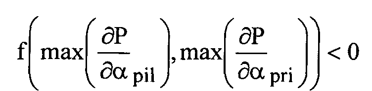


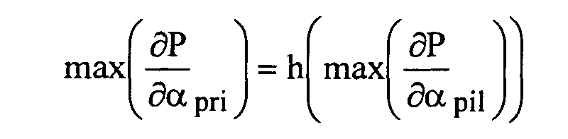


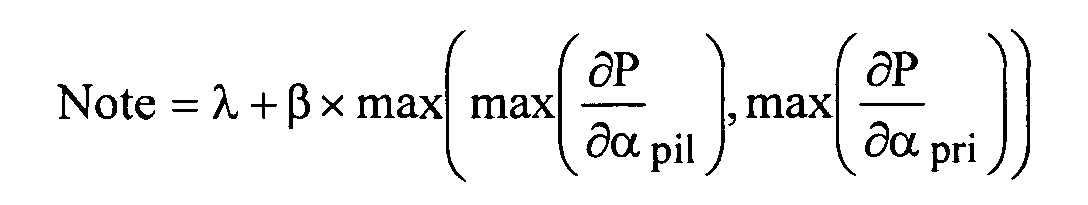
Applications Claiming Priority (2)
| Application Number | Priority Date | Filing Date | Title |
|---|---|---|---|
| FR0308351 | 2003-07-08 | ||
| FR0308351A FR2857410B1 (en) | 2003-07-08 | 2003-07-08 | SYSTEM FOR MONITORING COMBUSTION NOISE OF A DIESEL ENGINE OF A MOTOR VEHICLE |
Publications (2)
| Publication Number | Publication Date |
|---|---|
| EP1496237A1 true EP1496237A1 (en) | 2005-01-12 |
| EP1496237B1 EP1496237B1 (en) | 2009-12-09 |
Family
ID=33443248
Family Applications (1)
| Application Number | Title | Priority Date | Filing Date |
|---|---|---|---|
| EP04291699A Not-in-force EP1496237B1 (en) | 2003-07-08 | 2004-07-05 | System to control combustion noise of a diesel engine |
Country Status (5)
| Country | Link |
|---|---|
| US (1) | US6854441B2 (en) |
| EP (1) | EP1496237B1 (en) |
| AT (1) | ATE451546T1 (en) |
| DE (1) | DE602004024476D1 (en) |
| FR (1) | FR2857410B1 (en) |
Cited By (10)
| Publication number | Priority date | Publication date | Assignee | Title |
|---|---|---|---|---|
| EP1531253A3 (en) * | 2003-11-17 | 2005-06-29 | Toyota Jidosha Kabushiki Kaisha | Internal combustion engine control dependent on engine noise |
| FR2886729A1 (en) * | 2005-06-07 | 2006-12-08 | Peugeot Citroen Automobiles Sa | METHOD FOR DETERMINING THE LEVEL OF COMBUSTION NOISE OF AN INJECTION DIESEL ENGINE |
| FR2892464A1 (en) * | 2005-10-24 | 2007-04-27 | Bosch Gmbh Robert | Internal combustion engine e.g. diesel internal combustion engine, controlling method for vehicle, involves determining variable by comparing noise quantity with set point, where quantity is computed by balanced summation of characteristics |
| FR2907852A1 (en) * | 2006-10-25 | 2008-05-02 | Renault Sas | Fuel injector recalibrating method for e.g. oil engine of direct/indirect injection motor vehicle, involves recalibrating injection control patterns of injectors of cylinders for reducing difference between combustion noises |
| FR2908462A1 (en) * | 2006-11-15 | 2008-05-16 | Renault Sas | Controlling system for e.g. oil engine, has calculation unit to calculate pressure derivative, and controlling unit to compare measured and calculated values with limit values and modulate quantity of injected fuel during pilot injection |
| EP1930571A2 (en) * | 2006-12-05 | 2008-06-11 | Delphi Technologies, Inc. | Method of cylinder pressure sensor data/angle capture for low and high resolution |
| EP2110533A1 (en) * | 2008-04-17 | 2009-10-21 | Robert Bosch Gmbh | A pilot electronic control unit and a method to derive optimized look up tables |
| EP2184472A1 (en) | 2008-11-10 | 2010-05-12 | Delphi Technologies Holding S.à.r.l. | Engine Control System and Method |
| FR2945319A1 (en) * | 2009-05-11 | 2010-11-12 | Renault Sas | SYSTEM AND METHOD FOR CONTROLLING COMBUSTION IN AN INTERNAL COMBUSTION ENGINE. |
| EP2884080A3 (en) * | 2013-12-02 | 2016-01-20 | Toyota Jidosha Kabushiki Kaisha | Control device for internal combustion engine |
Families Citing this family (18)
| Publication number | Priority date | Publication date | Assignee | Title |
|---|---|---|---|---|
| FR2886679B1 (en) * | 2005-06-07 | 2007-10-05 | Peugeot Citroen Automobiles Sa | SYSTEM AND METHOD FOR CONTROLLING THE FUEL INJECTION OF A DIESEL ENGINE OF A MOTOR VEHICLE |
| FR2886678B1 (en) * | 2005-06-07 | 2007-09-28 | Peugeot Citroen Automobiles Sa | METHOD FOR REDUCING THE NOISE OF AN INJECTION DIESEL ENGINE |
| FR2890112B1 (en) * | 2005-08-30 | 2007-11-30 | Peugeot Citroen Automobiles Sa | SYSTEM FOR MONITORING THE OPERATION OF A DIESEL ENGINE OF A MOTOR VEHICLE EQUIPPED WITH EXHAUST GAS RECIRCULATION MEANS |
| US7255090B2 (en) * | 2005-12-15 | 2007-08-14 | Ford Global Technologies, Llc | Compression ignition engine with pressure-based combustion control |
| US7606655B2 (en) * | 2006-09-29 | 2009-10-20 | Delphi Technologies, Inc. | Cylinder-pressure-based electronic engine controller and method |
| FR2909762A1 (en) * | 2006-12-11 | 2008-06-13 | Renault Sas | Cylinder combustion noise determining system for internal combustion engine of motor vehicle, has determining module determining combustion noise in cylinder from selected pressure values in chamber of cylinder in real time |
| FR2917127B1 (en) | 2007-06-07 | 2009-07-10 | Renault Sas | METHOD FOR DETERMINING A COMBUSTION START IN AN INTERNAL COMBUSTION ENGINE |
| DE102007050302A1 (en) * | 2007-10-22 | 2009-04-23 | Robert Bosch Gmbh | Method and device for determining a cylinder pressure feature |
| GB2475062B (en) * | 2009-11-03 | 2012-07-04 | Gm Global Tech Operations Inc | Method for determining an index of the fuel combustion in an engine cylinder |
| US9255543B2 (en) * | 2012-12-14 | 2016-02-09 | Hyundai Motor Company | Fuel injection amount compensating method |
| SE537305C2 (en) * | 2013-04-25 | 2015-03-31 | Scania Cv Ab | Method and system for controlling an internal combustion engine through control of combustion in an internal combustion chamber during the current combustion cycle |
| SE537313C2 (en) * | 2013-04-25 | 2015-04-07 | Scania Cv Ab | Method and system for controlling an internal combustion engine through control of combustion in an internal combustion chamber during the current combustion cycle |
| KR101637700B1 (en) * | 2014-10-20 | 2016-07-07 | 현대자동차주식회사 | Method for Decreasing Engine Combustion Noise |
| US9670850B2 (en) * | 2014-11-25 | 2017-06-06 | Hyundai Motor Company | Combustion-noise controlling method for diesel engine |
| US9909522B2 (en) * | 2016-04-13 | 2018-03-06 | Jaguar Land Rover Limited | Method and apparatus for controlling an engine based on a target pressure curve |
| US9915210B2 (en) | 2016-04-13 | 2018-03-13 | Jaguar Land Rover Limited | Method and apparatus for controlling an engine based on a target pressure curve |
| CN114352418B (en) * | 2021-11-22 | 2023-04-07 | 江铃汽车股份有限公司 | Diesel engine starting noise optimization method and device, storage medium and equipment |
| CN114109636B (en) * | 2022-01-26 | 2022-08-30 | 潍柴动力股份有限公司 | Combustion control method for improving NVH performance of engine and engine |
Citations (4)
| Publication number | Priority date | Publication date | Assignee | Title |
|---|---|---|---|---|
| EP1128050A2 (en) * | 2000-02-25 | 2001-08-29 | Toyota Jidosha Kabushiki Kaisha | Fuel injection control apparatus |
| EP1219805A2 (en) * | 2000-12-19 | 2002-07-03 | Nissan Motor Co., Ltd. | Fuel injection control system and method |
| EP1316709A2 (en) * | 2001-12-01 | 2003-06-04 | Robert Bosch Gmbh | Method and apparatus for controlling an internal combustion engine |
| EP1316704A2 (en) * | 2001-12-01 | 2003-06-04 | Robert Bosch Gmbh | Method and apparatus for controlling an internal combustion engine |
Family Cites Families (1)
| Publication number | Priority date | Publication date | Assignee | Title |
|---|---|---|---|---|
| DE60000255T2 (en) * | 1999-09-22 | 2003-03-27 | Mitsubishi Motors Corp | Reservoir fuel injection device |
-
2003
- 2003-07-08 FR FR0308351A patent/FR2857410B1/en not_active Expired - Fee Related
-
2004
- 2004-07-05 EP EP04291699A patent/EP1496237B1/en not_active Not-in-force
- 2004-07-05 DE DE602004024476T patent/DE602004024476D1/en active Active
- 2004-07-05 AT AT04291699T patent/ATE451546T1/en not_active IP Right Cessation
- 2004-07-07 US US10/885,025 patent/US6854441B2/en not_active Expired - Fee Related
Patent Citations (4)
| Publication number | Priority date | Publication date | Assignee | Title |
|---|---|---|---|---|
| EP1128050A2 (en) * | 2000-02-25 | 2001-08-29 | Toyota Jidosha Kabushiki Kaisha | Fuel injection control apparatus |
| EP1219805A2 (en) * | 2000-12-19 | 2002-07-03 | Nissan Motor Co., Ltd. | Fuel injection control system and method |
| EP1316709A2 (en) * | 2001-12-01 | 2003-06-04 | Robert Bosch Gmbh | Method and apparatus for controlling an internal combustion engine |
| EP1316704A2 (en) * | 2001-12-01 | 2003-06-04 | Robert Bosch Gmbh | Method and apparatus for controlling an internal combustion engine |
Cited By (16)
| Publication number | Priority date | Publication date | Assignee | Title |
|---|---|---|---|---|
| EP1531253A3 (en) * | 2003-11-17 | 2005-06-29 | Toyota Jidosha Kabushiki Kaisha | Internal combustion engine control dependent on engine noise |
| FR2886729A1 (en) * | 2005-06-07 | 2006-12-08 | Peugeot Citroen Automobiles Sa | METHOD FOR DETERMINING THE LEVEL OF COMBUSTION NOISE OF AN INJECTION DIESEL ENGINE |
| WO2006131673A1 (en) * | 2005-06-07 | 2006-12-14 | Peugeot Citroën Automobiles Sa. | Method for determining an injection diesel engine combustion chamber noise level |
| FR2892464A1 (en) * | 2005-10-24 | 2007-04-27 | Bosch Gmbh Robert | Internal combustion engine e.g. diesel internal combustion engine, controlling method for vehicle, involves determining variable by comparing noise quantity with set point, where quantity is computed by balanced summation of characteristics |
| WO2008050033A3 (en) * | 2006-10-25 | 2008-06-19 | Renault Sa | Method of resetting the injectors of an engine and motor vehicle employing this method |
| FR2907852A1 (en) * | 2006-10-25 | 2008-05-02 | Renault Sas | Fuel injector recalibrating method for e.g. oil engine of direct/indirect injection motor vehicle, involves recalibrating injection control patterns of injectors of cylinders for reducing difference between combustion noises |
| WO2008050033A2 (en) * | 2006-10-25 | 2008-05-02 | Renault S.A.S. | Method of resetting the injectors of an engine and motor vehicle employing this method |
| FR2908462A1 (en) * | 2006-11-15 | 2008-05-16 | Renault Sas | Controlling system for e.g. oil engine, has calculation unit to calculate pressure derivative, and controlling unit to compare measured and calculated values with limit values and modulate quantity of injected fuel during pilot injection |
| EP1923558A1 (en) * | 2006-11-15 | 2008-05-21 | Renault s.a.s. | System and method of controlling an internal combustion engine |
| EP1930571A2 (en) * | 2006-12-05 | 2008-06-11 | Delphi Technologies, Inc. | Method of cylinder pressure sensor data/angle capture for low and high resolution |
| EP1930571A3 (en) * | 2006-12-05 | 2015-04-01 | Delphi Technologies, Inc. | Method of cylinder pressure sensor data/angle capture for low and high resolution |
| EP2110533A1 (en) * | 2008-04-17 | 2009-10-21 | Robert Bosch Gmbh | A pilot electronic control unit and a method to derive optimized look up tables |
| EP2184472A1 (en) | 2008-11-10 | 2010-05-12 | Delphi Technologies Holding S.à.r.l. | Engine Control System and Method |
| FR2945319A1 (en) * | 2009-05-11 | 2010-11-12 | Renault Sas | SYSTEM AND METHOD FOR CONTROLLING COMBUSTION IN AN INTERNAL COMBUSTION ENGINE. |
| EP2256322A1 (en) * | 2009-05-11 | 2010-12-01 | Renault S.A.S. | Effect of the NOx control on the combustion noise control in an internal combustion engine |
| EP2884080A3 (en) * | 2013-12-02 | 2016-01-20 | Toyota Jidosha Kabushiki Kaisha | Control device for internal combustion engine |
Also Published As
| Publication number | Publication date |
|---|---|
| US20050005902A1 (en) | 2005-01-13 |
| DE602004024476D1 (en) | 2010-01-21 |
| ATE451546T1 (en) | 2009-12-15 |
| EP1496237B1 (en) | 2009-12-09 |
| FR2857410A1 (en) | 2005-01-14 |
| FR2857410B1 (en) | 2005-10-14 |
| US6854441B2 (en) | 2005-02-15 |
Similar Documents
| Publication | Publication Date | Title |
|---|---|---|
| EP1496237B1 (en) | System to control combustion noise of a diesel engine | |
| EP1644627B1 (en) | Method for real-time determination of fuel injector flow characteristic | |
| FR2901847A1 (en) | Fuel injection controlling device for e.g. diesel engine, has acquisition device acquiring injection characteristics of injector in operating zone, and other acquisition device acquires characteristics based on fuel quantity in other zones | |
| FR2883332A1 (en) | METHOD AND DEVICE FOR MANAGING AN INTERNAL COMBUSTION ENGINE | |
| WO2014131508A1 (en) | Method for controlling a piezoelectric fuel injector of an internal combustion engine of a vehicle comprising a step for polarizing the piezoelectric actuator | |
| FR2780448A1 (en) | ENGINE MANAGEMENT DEVICE AND METHOD | |
| EP1936156B1 (en) | Method of controlling an internal combustion engine | |
| EP0686762A1 (en) | Method and apparatus for determining specific parameters of injectors for combustion engines, in particular diesel engines with pre-injection | |
| EP1058781B1 (en) | Method and device for fast automatic adaptation of richness for internal combustion engine | |
| EP3201443B1 (en) | Motor vehicle combustion engine with improved mixture strength control | |
| FR2859763A1 (en) | Internal combustion engine management process for use in motor vehicle, involves correcting fuel injection duration for injection in cylinder, before end of injection operation and during operation, based on fuel pressure in container | |
| FR2873163A1 (en) | SYSTEM FOR MONITORING THE OPERATION OF A DIESEL ENGINE OF A MOTOR VEHICLE ASSOCIATED WITH AN OXIDATION CATALYST | |
| EP1862659A1 (en) | Method and device for correcting the flow of a so-called pilot fuel injection in a direct-injection diesel engine of the common rail type, and engine comprising such a device | |
| EP1760295B1 (en) | Control system for a diesel engine equipped with exhaust recriculation means | |
| FR2851013A1 (en) | Pressure wave correcting process for motor vehicle, involves recording operational parameter value of internal combustion engine with time interval, between two control signals, if parameter and its wave have changed | |
| FR2718191A1 (en) | Suppression oscillation along automobile longitudinal axis | |
| WO2020193795A1 (en) | Determining a drift in the fuel static flow rate of a piezoelectric injector of a motor vehicle heat engine | |
| EP3215727B1 (en) | Method of estimation of a intake gas throttle position for control of an internal combustion engine | |
| FR3088965A1 (en) | METHOD FOR CORRECTING THE CONTROL OF A HEAT ENGINE | |
| FR2857057A1 (en) | Fuel injection system controlling method for internal combustion engine, involves transforming one correction function, by using individual quality characteristics of injectors, to another function to correct injector control signals | |
| EP1400679B1 (en) | Control system for operating a Diesel engine of an automotive vehicle | |
| EP2123889A1 (en) | Control process for internal combustion engine and device for implementing said process | |
| WO2023072565A1 (en) | Method for estimating the atmospheric pressure of an internal combustion engine | |
| FR2882399A1 (en) | SYSTEM FOR MONITORING THE OPERATION OF A DIESEL ENGINE OF A MOTOR VEHICLE EQUIPPED WITH EXHAUST GAS RECIRCULATION MEANS | |
| WO2004079176A1 (en) | Method for calculating fuel injector gain |
Legal Events
| Date | Code | Title | Description |
|---|---|---|---|
| PUAI | Public reference made under article 153(3) epc to a published international application that has entered the european phase |
Free format text: ORIGINAL CODE: 0009012 |
|
| AK | Designated contracting states |
Kind code of ref document: A1 Designated state(s): AT BE BG CH CY CZ DE DK EE ES FI FR GB GR HU IE IT LI LU MC NL PL PT RO SE SI SK TR |
|
| AX | Request for extension of the european patent |
Extension state: AL HR LT LV MK |
|
| 17P | Request for examination filed |
Effective date: 20050310 |
|
| AKX | Designation fees paid |
Designated state(s): AT BE BG CH CY CZ DE DK EE ES FI FR GB GR HU IE IT LI LU MC NL PL PT RO SE SI SK TR |
|
| GRAP | Despatch of communication of intention to grant a patent |
Free format text: ORIGINAL CODE: EPIDOSNIGR1 |
|
| GRAS | Grant fee paid |
Free format text: ORIGINAL CODE: EPIDOSNIGR3 |
|
| GRAA | (expected) grant |
Free format text: ORIGINAL CODE: 0009210 |
|
| AK | Designated contracting states |
Kind code of ref document: B1 Designated state(s): AT BE BG CH CY CZ DE DK EE ES FI FR GB GR HU IE IT LI LU MC NL PL PT RO SE SI SK TR |
|
| REG | Reference to a national code |
Ref country code: GB Ref legal event code: FG4D Free format text: NOT ENGLISH |
|
| REG | Reference to a national code |
Ref country code: CH Ref legal event code: EP |
|
| REG | Reference to a national code |
Ref country code: IE Ref legal event code: FG4D |
|
| REF | Corresponds to: |
Ref document number: 602004024476 Country of ref document: DE Date of ref document: 20100121 Kind code of ref document: P |
|
| REG | Reference to a national code |
Ref country code: NL Ref legal event code: VDEP Effective date: 20091209 |
|
| PG25 | Lapsed in a contracting state [announced via postgrant information from national office to epo] |
Ref country code: SE Free format text: LAPSE BECAUSE OF FAILURE TO SUBMIT A TRANSLATION OF THE DESCRIPTION OR TO PAY THE FEE WITHIN THE PRESCRIBED TIME-LIMIT Effective date: 20091209 Ref country code: FI Free format text: LAPSE BECAUSE OF FAILURE TO SUBMIT A TRANSLATION OF THE DESCRIPTION OR TO PAY THE FEE WITHIN THE PRESCRIBED TIME-LIMIT Effective date: 20091209 |
|
| PG25 | Lapsed in a contracting state [announced via postgrant information from national office to epo] |
Ref country code: PL Free format text: LAPSE BECAUSE OF FAILURE TO SUBMIT A TRANSLATION OF THE DESCRIPTION OR TO PAY THE FEE WITHIN THE PRESCRIBED TIME-LIMIT Effective date: 20091209 Ref country code: SI Free format text: LAPSE BECAUSE OF FAILURE TO SUBMIT A TRANSLATION OF THE DESCRIPTION OR TO PAY THE FEE WITHIN THE PRESCRIBED TIME-LIMIT Effective date: 20091209 |
|
| PG25 | Lapsed in a contracting state [announced via postgrant information from national office to epo] |
Ref country code: AT Free format text: LAPSE BECAUSE OF FAILURE TO SUBMIT A TRANSLATION OF THE DESCRIPTION OR TO PAY THE FEE WITHIN THE PRESCRIBED TIME-LIMIT Effective date: 20091209 |
|
| REG | Reference to a national code |
Ref country code: IE Ref legal event code: FD4D |
|
| PG25 | Lapsed in a contracting state [announced via postgrant information from national office to epo] |
Ref country code: RO Free format text: LAPSE BECAUSE OF FAILURE TO SUBMIT A TRANSLATION OF THE DESCRIPTION OR TO PAY THE FEE WITHIN THE PRESCRIBED TIME-LIMIT Effective date: 20091209 Ref country code: NL Free format text: LAPSE BECAUSE OF FAILURE TO SUBMIT A TRANSLATION OF THE DESCRIPTION OR TO PAY THE FEE WITHIN THE PRESCRIBED TIME-LIMIT Effective date: 20091209 Ref country code: ES Free format text: LAPSE BECAUSE OF FAILURE TO SUBMIT A TRANSLATION OF THE DESCRIPTION OR TO PAY THE FEE WITHIN THE PRESCRIBED TIME-LIMIT Effective date: 20100320 Ref country code: PT Free format text: LAPSE BECAUSE OF FAILURE TO SUBMIT A TRANSLATION OF THE DESCRIPTION OR TO PAY THE FEE WITHIN THE PRESCRIBED TIME-LIMIT Effective date: 20100409 Ref country code: BG Free format text: LAPSE BECAUSE OF FAILURE TO SUBMIT A TRANSLATION OF THE DESCRIPTION OR TO PAY THE FEE WITHIN THE PRESCRIBED TIME-LIMIT Effective date: 20100309 Ref country code: EE Free format text: LAPSE BECAUSE OF FAILURE TO SUBMIT A TRANSLATION OF THE DESCRIPTION OR TO PAY THE FEE WITHIN THE PRESCRIBED TIME-LIMIT Effective date: 20091209 Ref country code: IE Free format text: LAPSE BECAUSE OF FAILURE TO SUBMIT A TRANSLATION OF THE DESCRIPTION OR TO PAY THE FEE WITHIN THE PRESCRIBED TIME-LIMIT Effective date: 20091209 |
|
| PG25 | Lapsed in a contracting state [announced via postgrant information from national office to epo] |
Ref country code: CZ Free format text: LAPSE BECAUSE OF FAILURE TO SUBMIT A TRANSLATION OF THE DESCRIPTION OR TO PAY THE FEE WITHIN THE PRESCRIBED TIME-LIMIT Effective date: 20091209 Ref country code: SK Free format text: LAPSE BECAUSE OF FAILURE TO SUBMIT A TRANSLATION OF THE DESCRIPTION OR TO PAY THE FEE WITHIN THE PRESCRIBED TIME-LIMIT Effective date: 20091209 |
|
| PLBE | No opposition filed within time limit |
Free format text: ORIGINAL CODE: 0009261 |
|
| STAA | Information on the status of an ep patent application or granted ep patent |
Free format text: STATUS: NO OPPOSITION FILED WITHIN TIME LIMIT |
|
| PG25 | Lapsed in a contracting state [announced via postgrant information from national office to epo] |
Ref country code: GR Free format text: LAPSE BECAUSE OF FAILURE TO SUBMIT A TRANSLATION OF THE DESCRIPTION OR TO PAY THE FEE WITHIN THE PRESCRIBED TIME-LIMIT Effective date: 20100310 Ref country code: CY Free format text: LAPSE BECAUSE OF FAILURE TO SUBMIT A TRANSLATION OF THE DESCRIPTION OR TO PAY THE FEE WITHIN THE PRESCRIBED TIME-LIMIT Effective date: 20091209 |
|
| 26N | No opposition filed |
Effective date: 20100910 |
|
| PGFP | Annual fee paid to national office [announced via postgrant information from national office to epo] |
Ref country code: DE Payment date: 20100706 Year of fee payment: 7 |
|
| BERE | Be: lapsed |
Owner name: PEUGEOT CITROEN AUTOMOBILES S.A. Effective date: 20100731 Owner name: DELPHI TECHNOLOGIES, INC. Effective date: 20100731 |
|
| PG25 | Lapsed in a contracting state [announced via postgrant information from national office to epo] |
Ref country code: DK Free format text: LAPSE BECAUSE OF FAILURE TO SUBMIT A TRANSLATION OF THE DESCRIPTION OR TO PAY THE FEE WITHIN THE PRESCRIBED TIME-LIMIT Effective date: 20091209 |
|
| PG25 | Lapsed in a contracting state [announced via postgrant information from national office to epo] |
Ref country code: MC Free format text: LAPSE BECAUSE OF NON-PAYMENT OF DUE FEES Effective date: 20100731 |
|
| REG | Reference to a national code |
Ref country code: CH Ref legal event code: PL |
|
| PG25 | Lapsed in a contracting state [announced via postgrant information from national office to epo] |
Ref country code: CH Free format text: LAPSE BECAUSE OF NON-PAYMENT OF DUE FEES Effective date: 20100731 Ref country code: LI Free format text: LAPSE BECAUSE OF NON-PAYMENT OF DUE FEES Effective date: 20100731 |
|
| PG25 | Lapsed in a contracting state [announced via postgrant information from national office to epo] |
Ref country code: BE Free format text: LAPSE BECAUSE OF NON-PAYMENT OF DUE FEES Effective date: 20100731 |
|
| PGFP | Annual fee paid to national office [announced via postgrant information from national office to epo] |
Ref country code: IT Payment date: 20110618 Year of fee payment: 8 |
|
| PGFP | Annual fee paid to national office [announced via postgrant information from national office to epo] |
Ref country code: GB Payment date: 20110701 Year of fee payment: 8 |
|
| PG25 | Lapsed in a contracting state [announced via postgrant information from national office to epo] |
Ref country code: DE Free format text: LAPSE BECAUSE OF NON-PAYMENT OF DUE FEES Effective date: 20120201 |
|
| REG | Reference to a national code |
Ref country code: DE Ref legal event code: R119 Ref document number: 602004024476 Country of ref document: DE Effective date: 20120201 |
|
| PG25 | Lapsed in a contracting state [announced via postgrant information from national office to epo] |
Ref country code: HU Free format text: LAPSE BECAUSE OF FAILURE TO SUBMIT A TRANSLATION OF THE DESCRIPTION OR TO PAY THE FEE WITHIN THE PRESCRIBED TIME-LIMIT Effective date: 20100610 Ref country code: LU Free format text: LAPSE BECAUSE OF NON-PAYMENT OF DUE FEES Effective date: 20100705 |
|
| PG25 | Lapsed in a contracting state [announced via postgrant information from national office to epo] |
Ref country code: TR Free format text: LAPSE BECAUSE OF FAILURE TO SUBMIT A TRANSLATION OF THE DESCRIPTION OR TO PAY THE FEE WITHIN THE PRESCRIBED TIME-LIMIT Effective date: 20091209 |
|
| PGFP | Annual fee paid to national office [announced via postgrant information from national office to epo] |
Ref country code: FR Payment date: 20120806 Year of fee payment: 9 |
|
| GBPC | Gb: european patent ceased through non-payment of renewal fee |
Effective date: 20120705 |
|
| PG25 | Lapsed in a contracting state [announced via postgrant information from national office to epo] |
Ref country code: GB Free format text: LAPSE BECAUSE OF NON-PAYMENT OF DUE FEES Effective date: 20120705 |
|
| PG25 | Lapsed in a contracting state [announced via postgrant information from national office to epo] |
Ref country code: IT Free format text: LAPSE BECAUSE OF NON-PAYMENT OF DUE FEES Effective date: 20120705 |
|
| REG | Reference to a national code |
Ref country code: FR Ref legal event code: ST Effective date: 20140331 |
|
| PG25 | Lapsed in a contracting state [announced via postgrant information from national office to epo] |
Ref country code: FR Free format text: LAPSE BECAUSE OF NON-PAYMENT OF DUE FEES Effective date: 20130731 |