EP1316709A2 - Method and apparatus for controlling an internal combustion engine - Google Patents
Method and apparatus for controlling an internal combustion engine Download PDFInfo
- Publication number
- EP1316709A2 EP1316709A2 EP02023104A EP02023104A EP1316709A2 EP 1316709 A2 EP1316709 A2 EP 1316709A2 EP 02023104 A EP02023104 A EP 02023104A EP 02023104 A EP02023104 A EP 02023104A EP 1316709 A2 EP1316709 A2 EP 1316709A2
- Authority
- EP
- European Patent Office
- Prior art keywords
- injection
- internal combustion
- combustion engine
- ignition delay
- burning
- Prior art date
- Legal status (The legal status is an assumption and is not a legal conclusion. Google has not performed a legal analysis and makes no representation as to the accuracy of the status listed.)
- Withdrawn
Links
Images


Classifications
-
- F—MECHANICAL ENGINEERING; LIGHTING; HEATING; WEAPONS; BLASTING
- F02—COMBUSTION ENGINES; HOT-GAS OR COMBUSTION-PRODUCT ENGINE PLANTS
- F02D—CONTROLLING COMBUSTION ENGINES
- F02D41/00—Electrical control of supply of combustible mixture or its constituents
- F02D41/02—Circuit arrangements for generating control signals
- F02D41/04—Introducing corrections for particular operating conditions
- F02D41/06—Introducing corrections for particular operating conditions for engine starting or warming up
- F02D41/062—Introducing corrections for particular operating conditions for engine starting or warming up for starting
- F02D41/064—Introducing corrections for particular operating conditions for engine starting or warming up for starting at cold start
-
- F—MECHANICAL ENGINEERING; LIGHTING; HEATING; WEAPONS; BLASTING
- F02—COMBUSTION ENGINES; HOT-GAS OR COMBUSTION-PRODUCT ENGINE PLANTS
- F02D—CONTROLLING COMBUSTION ENGINES
- F02D35/00—Controlling engines, dependent on conditions exterior or interior to engines, not otherwise provided for
- F02D35/02—Controlling engines, dependent on conditions exterior or interior to engines, not otherwise provided for on interior conditions
- F02D35/023—Controlling engines, dependent on conditions exterior or interior to engines, not otherwise provided for on interior conditions by determining the cylinder pressure
-
- F—MECHANICAL ENGINEERING; LIGHTING; HEATING; WEAPONS; BLASTING
- F02—COMBUSTION ENGINES; HOT-GAS OR COMBUSTION-PRODUCT ENGINE PLANTS
- F02D—CONTROLLING COMBUSTION ENGINES
- F02D35/00—Controlling engines, dependent on conditions exterior or interior to engines, not otherwise provided for
- F02D35/02—Controlling engines, dependent on conditions exterior or interior to engines, not otherwise provided for on interior conditions
- F02D35/028—Controlling engines, dependent on conditions exterior or interior to engines, not otherwise provided for on interior conditions by determining the combustion timing or phasing
-
- F—MECHANICAL ENGINEERING; LIGHTING; HEATING; WEAPONS; BLASTING
- F02—COMBUSTION ENGINES; HOT-GAS OR COMBUSTION-PRODUCT ENGINE PLANTS
- F02D—CONTROLLING COMBUSTION ENGINES
- F02D41/00—Electrical control of supply of combustible mixture or its constituents
- F02D41/30—Controlling fuel injection
- F02D41/38—Controlling fuel injection of the high pressure type
- F02D41/40—Controlling fuel injection of the high pressure type with means for controlling injection timing or duration
- F02D41/402—Multiple injections
- F02D41/403—Multiple injections with pilot injections
-
- F—MECHANICAL ENGINEERING; LIGHTING; HEATING; WEAPONS; BLASTING
- F02—COMBUSTION ENGINES; HOT-GAS OR COMBUSTION-PRODUCT ENGINE PLANTS
- F02D—CONTROLLING COMBUSTION ENGINES
- F02D2200/00—Input parameters for engine control
- F02D2200/02—Input parameters for engine control the parameters being related to the engine
- F02D2200/025—Engine noise, e.g. determined by using an acoustic sensor
-
- F—MECHANICAL ENGINEERING; LIGHTING; HEATING; WEAPONS; BLASTING
- F02—COMBUSTION ENGINES; HOT-GAS OR COMBUSTION-PRODUCT ENGINE PLANTS
- F02D—CONTROLLING COMBUSTION ENGINES
- F02D35/00—Controlling engines, dependent on conditions exterior or interior to engines, not otherwise provided for
- F02D35/02—Controlling engines, dependent on conditions exterior or interior to engines, not otherwise provided for on interior conditions
- F02D35/021—Controlling engines, dependent on conditions exterior or interior to engines, not otherwise provided for on interior conditions using an ionic current sensor
-
- F—MECHANICAL ENGINEERING; LIGHTING; HEATING; WEAPONS; BLASTING
- F02—COMBUSTION ENGINES; HOT-GAS OR COMBUSTION-PRODUCT ENGINE PLANTS
- F02D—CONTROLLING COMBUSTION ENGINES
- F02D35/00—Controlling engines, dependent on conditions exterior or interior to engines, not otherwise provided for
- F02D35/02—Controlling engines, dependent on conditions exterior or interior to engines, not otherwise provided for on interior conditions
- F02D35/022—Controlling engines, dependent on conditions exterior or interior to engines, not otherwise provided for on interior conditions using an optical sensor, e.g. in-cylinder light probe
-
- F—MECHANICAL ENGINEERING; LIGHTING; HEATING; WEAPONS; BLASTING
- F02—COMBUSTION ENGINES; HOT-GAS OR COMBUSTION-PRODUCT ENGINE PLANTS
- F02D—CONTROLLING COMBUSTION ENGINES
- F02D41/00—Electrical control of supply of combustible mixture or its constituents
- F02D41/02—Circuit arrangements for generating control signals
- F02D41/04—Introducing corrections for particular operating conditions
- F02D41/047—Taking into account fuel evaporation or wall wetting
-
- Y—GENERAL TAGGING OF NEW TECHNOLOGICAL DEVELOPMENTS; GENERAL TAGGING OF CROSS-SECTIONAL TECHNOLOGIES SPANNING OVER SEVERAL SECTIONS OF THE IPC; TECHNICAL SUBJECTS COVERED BY FORMER USPC CROSS-REFERENCE ART COLLECTIONS [XRACs] AND DIGESTS
- Y02—TECHNOLOGIES OR APPLICATIONS FOR MITIGATION OR ADAPTATION AGAINST CLIMATE CHANGE
- Y02T—CLIMATE CHANGE MITIGATION TECHNOLOGIES RELATED TO TRANSPORTATION
- Y02T10/00—Road transport of goods or passengers
- Y02T10/10—Internal combustion engine [ICE] based vehicles
- Y02T10/40—Engine management systems
Definitions
- the invention relates to a method and a device to control an internal combustion engine according to General terms of the independent claims.
- DE 39 29 747 describes a method and a device to control an internal combustion engine, in which the Duration of the control is determined, at which one Pre-injection starts. This determined minimum duration is used to correct the control.
- the Ignition delay i.e. the time between the start of burning and the associated start of injection is an essential variable, which affects the noise emissions.
- the correction is particularly important for pre-injection advantageous because there are small deviations due to Tolerances have a great influence.
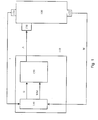
- FIG. 1 shows a block diagram of a device for carrying out the method according to the invention
- FIG. 2 shows a flow diagram of an embodiment of the method according to the invention
- FIG. 3 shows a controller structure.
- FIG a block diagram An internal combustion engine is designated 100. On the internal combustion engine is for an at least one sensor 120 and an angle sensor 122 arranged.
- the sensor 120 provides a signal I that the Electricity through a in the combustion chamber of the internal combustion engine arranged ion current probe characterized.
- a sensor is provided, which is arranged on a representative cylinder.
- a second embodiment is the for each cylinder Internal combustion engine arranged a sensor, each one Emits signal.
- the angle sensor 122 is preferably on the crankshaft Internal combustion engine arranged and delivers high-resolution angle signal W with respect to the angular position the crankshaft. Alternatively, the angle sensor can also be switched on the camshaft of the internal combustion engine.
- actuator 130 on the internal combustion engine arranged.
- the actuator and the sensors are with one Control unit 110 in connection.
- the signal I of the sensor 120 and the signal W des Angle sensor 122 arrive at an evaluation unit 140 which preferably forms a subunit of the control unit 110.
- the evaluation unit 140 supplies a signal II to one Functional unit 150.
- the functional unit in turn applies a manipulated variable A to actuator 130.
- the manipulated variable A is preferably the Driving times and / or the start of driving one Injection. It is preferably provided that a Injection process of the working cycle in several Partial injections is divided. It is about the manipulated variable A by the control duration and / or the Start of control of at least one of the partial injections.
- Partial injections are usually at least one Main injection, at least one pre-injection and at least one post-injection is provided. In particular in the pre-injection is the invention Procedure advantageous.
- the courses of the signals I are preferred Cylinder detected individually by sensors.
- An alternative is that only one is treated as representative Cylinder is provided with a signal detection.
- a high-resolution angle signal W is used as a reference used to calculate the angular position can.
- the sensor signals I and the angle W become the Evaluation unit 140, which is typically part of the Motor control is fed. Your job is education a size II, which is preferably the actual size of a regulation is fed.
- the area of the injection components is the same Control signal for the injection components one different amount of fuel metered.
- the desired pilot injection quantity or even one large pre-injection quantity is metered. If one becomes too small Pre-injection quantity supplied, so the pre-injection works not, that means the noises are not reduced. Becomes supplied too large a pre-injection quantity, so deteriorate the exhaust gas values.
- the Control duration is determined at which the desired Pre-injection quantity is metered. That amount is like that chosen that a pre-injection takes place that the has the desired influence on the combustion, but does not adversely affect emissions.
- the activation duration starts from a zero value at which there is certainly no injection takes place, is increased.
- a size is recorded which characterizes the ignition delay.
- the value of the Control duration which is the size that the ignition delay characterized, no longer changes significantly, is then called Standard value used. When using this standard value for the The desired pilot injection quantity is activated meted out.
- the start of burning especially the following Main injection, used. Particularly advantageous here it is when the start of burning starts from the signal of a Ion current sensor is formed.
- the control duration for the Pre-injection preferably 0 ms in suitable Steps up to a maximum value at which all Conditions effective pre-injection takes place increased.
- the calculation of the Start of burning based on the ion current signal.
- the values of the start of burning for the individual control times determined several times. Starting from These values are then averaged. From this the result is a table that shows the activation times Assigned start of burning.
- the ignition delay is reduced, the distance between control and start of burning corresponds with increasing control duration. From one certain trigger duration the ignition delay or the beginning of burning no longer. This drive duration at which Ignition delay or the start of burning changes to saturation is used as the optimal trigger duration for the pre-injection viewed and used as a standard value for control.
- a determination of the norm value AD0 is shown in Figure 2.
- the Control duration for the pre-injection to a value set in which none in all operating states Injection takes place.
- the control duration is preferred set to 0 ms.
- step 310 the activation period ADVE is increased by one certain value X increased.
- step 320 the current start of burning BN is determined. This happens preferably by evaluating a signal from a Ion current sensor. For example, at the start of burning detected when the output signal of the ion current sensor is a Threshold exceeds. Instead of starting to burn also another signal that the start of burning and / or the Ignition delay can be characterized.
- step 330 we get the amount of the difference between the current value BN and the previous value BA of the start of burning as a size DB.
- This subsequent query 340 checks whether this Size DB is less than a threshold SW. Is this the Fall, that is, the start of burning has been going on since the last Change in control duration no longer significantly changed the current activation period ADVE is then in step 360 as Standard value AD0 saved.
- Query 340 detects that size DB is not less than one Threshold is SW. If so, that is Burning has changed since the last change in Control duration changed significantly, so in step 350 the previous value BA with the current value BN overwritten. This is followed by step 310 further increase in the activation period.
- the Course of the pre-injection to a specific setpoint is regulated. That means the duration of the pre-injection extended or shortened until the course of the Pre-injection has an expected course. there are not the course of the pre-injection directly, but a substitute size that correlates well with the course is adjusted to the setpoint.
- the Substitute size chosen such that the noise emissions and exhaust emissions are minimized.
- FIG. 3a Such a regulation is exemplified in FIG. 3a shown.
- This scheme is preferably part of the Functional unit 150. Already described in FIG. 1 Elements are identified by corresponding reference symbols.
- the evaluation unit 140 provides a connection point 210 an actual value II is available.
- a setpoint IS At the second entrance of the Link point 210 is a setpoint IS, which of a setpoint specification 220 is provided.
- the output signal of node 210 becomes a controller 200 acted upon, which in turn the first and / or the actuator 130 applied with control signals A.
- controller 200 outputs a Correction value for the correction of the control period A for the Pre-injection before.
- a corresponding embodiment is shown in Figure 3b. Already described in Figure 3a Elements are identified by corresponding reference symbols. This embodiment differs from FIG. 3a in essentially in that the control duration A for the Pre-injection depending on different operating parameters can be specified by a specification 230. This one so given Value A is then compared with the output value K of controller 200 Link point 240 additive and / or multiplicative corrected.
- correction value K can be stored in a storage means 205. This is it is possible if the ion current sensor fails and / or in operating states in which no regulation is possible a correction with the stored values K perform. This embodiment is dashed shown.
- the pre-injection quantity is via a substitute signal adjusted to a setpoint.
- the setpoint for that Substitute signal of this regulation is chosen so that the Pilot injection quantity is as large as it is required to limit noise emissions.
- the Setpoint value of the substitute signal selected so that the Pre-injection quantity is so small that it is as small as possible Exhaust emissions occur.
- An ion current sensor is preferably used as the sensor, whose signal due to the combustion negative (electrons) and positively charged particles and the associated conductivity arises.
- the ion current increases with the start of combustion.
- the Rise in the ion current characterizes the start of burning.
- the start of burning corresponds to that Time when the output signal of the ion current sensor rises above a certain threshold.
- the distance between the start of injection and the start of combustion is referred to as ignition delay.
- the ignition delay and / or the start of burning regulated to a certain value.
- the control duration continues extended, the ignition delay is further reduced. at a certain control duration decreases Ignition delay no further.
- the ignition delay is at this value at which the ignition delay is no longer regulated.
- the start of burning of the Main injection to be regulated to a certain value.
- the Ion current sensor other sensors can be used Provide signals that characterize the combustion.
- combustion chamber pressure sensors Structure-borne noise sensors, optical sensors are used.
- derived from these sensor signals or from quantities calculated from these signals are used as actual value II become.
- the combustion chamber pressure signal In addition to the Ion current signal also the combustion chamber pressure signal exposed. Especially after time and / or after cylinder pressure signal differentiated from the crank angle directly and indirectly additional information about the type of energy conversion and its effect on the motor behavior, e.g. regarding combustion noise or loading of the piston rings.
- the pressure signal is preferably evaluated with respect to the feature size pressure gradient GP, this preferably by differentiation over the angle W according to of the formula dP / dW or by differentiation over time t according to the formula dP / dt. In particular, a absolute maximum or several relative maximum Pressure gradient and his / her location (s) determined.
- the maximum pressure increase occurring in a cylinder significantly influences the combustion noise and thus also the total noise emission of the internal combustion engine.
- the Application of the setpoints in a conventional Engine control can indirectly also comply certain limits of the target value combustion noise Take into account.
- a single internal combustion engine included however, its injection device gives way different effects from those only indirect predetermined target values of the maximum pressure gradient. These effects are in particular: the entirety of all Tolerances, signs of wear and aging, in the Setpoints not taken into account or not sufficiently taken into account Operating conditions.
- the essential values are the maximum values and / or the Angular position of higher derivatives, especially the 2nd Derivation, the cylinder pressure curve according to the crank angle and / or according to time.
- thermodynamic to be calculated from the pressure curve Feature sizes such as the Heating process, the burning process, the total heating process and / or the total combustion process is particularly suitable.
- the course of heating denotes that caused by the combustion of the Working gas transferring heat per crank angle.
- the unit the heating process is usually [J / ° KW] or corresponding conversions.
- the firing process represents one analog size. In contrast to the heating process included however, the burning process the whole, during the combustion released heat. The firing process is now in essentially around the flowing off over the combustion chamber walls Heat per angular unit greater than the heating curve.
- thermodynamics the course of heating and / or the course of burning at Knowledge of calorific data of fuel gas and fuel as well Engine geometry data with the help of certain Model assumptions calculated from the cylinder pressure curve.
- the total heating curve represents the integral of the Heating curve over the crank angle
- Total combustion curve corresponds to the integral of the Burning course over the crank angle
- Further values are the maximum values and / or their Angular positions of different leads, especially the first derivative and the second derivative of the above Sizes, such as heating curve, burning curve, Total heating curve or total burning curve, after Crank angle or according to time.
- the firing process is based on a model that the includes thermodynamic consideration of the combustion chamber, certainly.
- the most important measurement is the cylinder pressure. E.g. the introduction of the fuel into the combustion chamber, which corresponds to the mass flow to the combustion chamber, and the subsequent evaporation, which is the heat flow from the Working gas corresponds, not modeled, then it shows the combustion curve calculated for the cylinder pressure curve characteristic minimum at the beginning of the injection.
- the amount of energy this minimum into a proportional injection mass ⁇ mB can be converted.
- ⁇ mB * r, where r is the corresponds to the specific heat of vaporization of the fuel.
- a common rail system is at least Rail pressure and the control duration, supplemented by Geometry parameters of the injection system to be taken into account.
- the speed is too instead of the rail pressure consider. In both cases, the consideration the measured variable fuel temperature advantageous.
Landscapes
- Engineering & Computer Science (AREA)
- Chemical & Material Sciences (AREA)
- Combustion & Propulsion (AREA)
- Mechanical Engineering (AREA)
- General Engineering & Computer Science (AREA)
- Electrical Control Of Air Or Fuel Supplied To Internal-Combustion Engine (AREA)
- Combined Controls Of Internal Combustion Engines (AREA)
Abstract
Description
Die Erfindung betrifft ein Verfahren und eine Vorrichtung zur Steuerung einer Brennkraftmaschine gemäß den Oberbegriffen der unabhängigen Ansprüche.The invention relates to a method and a device to control an internal combustion engine according to General terms of the independent claims.
Aus der DE 39 29 747 ist ein Verfahren und eine Vorrichtung zur Steuerung einer Brennkraftmaschine bekannt, bei der die Dauer der Ansteuerung ermittelt wird, bei der gerade eine Voreinspritzung einsetzt. Diese ermittelte Mindestdauer wird zur Korrektur der Ansteuerung eingesetzt.DE 39 29 747 describes a method and a device to control an internal combustion engine, in which the Duration of the control is determined, at which one Pre-injection starts. This determined minimum duration is used to correct the control.
Dadurch, dass bei einem Verfahren und einer Vorrichtung zur Steuerung einer Brennkraftmaschine, bei dem eine Ansteuerdauer einer Teileinspritzung ausgehend von dem Vergleich einer ersten Größe mit einem Sollwert korrigiert wird, wobei die erste Größe den Verlauf der Teileinspritzung charakterisiert, ist eine sehr genaue Korrektur der Voreinspritzmenge während des Motorbetriebs möglich. Fehler, die auf Exemplarstreuungen und/oder Alterungseffekten von Motor und Einspritzsystem beruhen können weitestgehend kompensiert werden. Besonders vorteilhaft ist, dass die Vorgehensweise nicht nur in bestimmten Betriebszuständen erfolgen kann, sondern dass sie in nahezu allen Betriebszuständen möglich ist. Insbesondere ist eine Korrektur bei unterschiedlichen Raildrücken, Drehzahlen und Lasten möglich.The fact that in a method and an apparatus for Control of an internal combustion engine, in which a Control duration of a partial injection based on the Corrected comparison of a first variable with a target value , the first variable being the course of the partial injection characterized is a very accurate correction of the Pre-injection quantity possible during engine operation. Error, based on copy variations and / or aging effects of The engine and injection system can largely be based be compensated. It is particularly advantageous that the Procedure not only in certain operating states can be done, but that they are in almost all Operating states is possible. One is in particular Correction at different rail pressures, speeds and Loads possible.
Besonders vorteilhaft ist es, wenn die erste Größe den Brennbeginn der Haupteinspritzung charakterisiert. Der Zündverzug, das heißt die Zeit zwischen Brennbeginn und dazugehörigem Einspritzbeginn ist eine wesentliche Größe, die die Geräuschemissionen beeinflußt.It is particularly advantageous if the first size Characterized the start of combustion of the main injection. The Ignition delay, i.e. the time between the start of burning and the associated start of injection is an essential variable, which affects the noise emissions.
Insbesondere bei der Voreinspritzung ist die Korrektur vorteilhaft, da hier kleine Abweichungen auf Grund von Toleranzen einen großen Einfluß besitzten.The correction is particularly important for pre-injection advantageous because there are small deviations due to Tolerances have a great influence.
Die Auswertung eines Signals eines Ionenstromsensors hat sich als besonders Vorteilhaft erwiesen, da dieses Signal den Verlauf der Verbrennung gut nachbildet. Entsprechendes gilt im besonderen für einen Brennraumdrucksensor.The evaluation of a signal from an ion current sensor has proved to be particularly advantageous because of this signal reproduces the course of the combustion well. The same applies in particular to a combustion chamber pressure sensor.
Neben den Signalen dieser Sensoren können auch aus diesen Sensorsignalen abgeleitete Größen zur Korrektur verwendet werden.In addition to the signals from these sensors, these can also be used Variables derived from sensor signals are used for correction become.
Die Erfindung wird nachstehend anhand der in der Zeichnung
dargestellten Ausführungsbeispiele erläutert.
Es zeigen die Figur 1 ein Blockschaltbild einer Einrichtung
zur Durchführung des erfindungsgemäßen Verfahrens, Figur 2
ein Flußdiagramm einer Ausführungsform des erfindungsgemäßen
Verfahrens und die Figur 3 eine Reglerstruktur. The invention is explained below with reference to the embodiments shown in the drawing.
FIG. 1 shows a block diagram of a device for carrying out the method according to the invention, FIG. 2 shows a flow diagram of an embodiment of the method according to the invention and FIG. 3 shows a controller structure.
In Figur 1 ist die erfindungsgemäße Vorgehensweise anhand
eines Blockdiagrammes dargestellt. Eine Brennkraftmaschine
ist mit 100 bezeichnet. An der Brennkraftmaschine ist zum
einen wenigstens ein Sensor 120 und ein Winkelsensor 122
angeordnet. Der Sensor 120 liefert ein Signal I, das den
Strom, der durch eine im Brennraum der Brennkraftmaschine
angeordneten Ionenstromsonde charakterisiert. Bei einer
ersten Ausgestaltung ist lediglich ein Sensor vorgesehen,
der an einem repräsentierenden Zylinder angeordnet ist. Bei
einer zweiten Ausgestaltung ist bei jedem Zylinder der
Brennkraftmaschine ein Sensor angeordnet, der jeweils ein
Signal abgibt.The procedure according to the invention is shown in FIG
a block diagram. An internal combustion engine
is designated 100. On the internal combustion engine is for
an at least one
Der Winkelsensor 122 ist vorzugsweise an der Kurbelwelle der
Brennkraftmaschine angeordnet und liefert ein
hochauflösendes Winkelsignal W bezüglich der Winkelstellung
der Kurbelwelle. Alternativ kann der Winkelsensor auch an
der Nockenwelle der Brennkraftmaschine angeordnet sein.The
Desweiteren sind an der Brennkraftmaschine ein Steller 130
angeordnet. Der Steller und die Sensoren stehen mit einer
Steuereinheit 110 in Verbindung.Furthermore, there is an
Das Signal I des Sensors 120 und das Signal W des
Winkelsensors 122 gelangen zu einer Auswerteeinheit 140, die
vorzugsweise eine Teileinheit der Steuereinheit 110 bildet.
Die Auswerteeinheit 140 liefert ein Signal II an eine
Funktionseinheit 150. Die Funktionseinheit wiederum
beaufschlagt den Steller 130 mit einer Stellgröße A.The signal I of the
Bei der Stellgröße A handelt es sich vorzugsweise um die Ansteuerdauern und/oder die Ansteuerbeginne einer Einspritzung. Vorzugsweise ist vorgesehen, dass ein Einspritzvorgang des Arbeitszyklusses in mehrere Teileinspritzungen aufgeteilt ist. Dabei handelt es sich bei der Stellgröße A um die Ansteuerdauer und/oder den Ansteuerbeginn wenigstens einer der Teileinspritzungen. Als Teileinspritzungen sind üblicherweise wenigstens eine Haupteinspritzung, wenigstens eine Voreinspritzung und wenigstens eine Nacheinspritzung vorgesehen. Insbesondere bei der Voreinspritzung ist die erfindungsgemäße Vorgehensweise vorteilhaft.The manipulated variable A is preferably the Driving times and / or the start of driving one Injection. It is preferably provided that a Injection process of the working cycle in several Partial injections is divided. It is about the manipulated variable A by the control duration and / or the Start of control of at least one of the partial injections. As Partial injections are usually at least one Main injection, at least one pre-injection and at least one post-injection is provided. In particular in the pre-injection is the invention Procedure advantageous.
Vorzugsweise werden die Verläufe der Singale I aller Zylinder einzeln durch Sensoren erfasst. Eine Alternative besteht darin, dass nur ein als repräsentativ behandelter Zylinder mit einer Signalerfassung versehen ist. In beiden Fällen wird ein hochaufgelöstes Winkelsignal W als Bezugsgröße verwendet, um zum einen die Winkellage berechnen zu können.The courses of the signals I are preferred Cylinder detected individually by sensors. An alternative is that only one is treated as representative Cylinder is provided with a signal detection. In both Cases, a high-resolution angle signal W is used as a reference used to calculate the angular position can.
Die Sensorsignale I und der Winkel W werden der
Auswerteeinheit 140, die typischerweise ein Bestandteil der
Motorsteuerung ist, zugeführt. Ihre Aufgabe ist die Bildung
einer Größe II, die vorzugsweise als Istgröße einer Regelung
zugeführt wird.The sensor signals I and the angle W become the
Auf Grund von Toleranzen und/oder Alterungseffekten im Bereich der Einspritzkomponenten wird bei gleichem Ansteuersignal für die Einspritzkomponenten eine unterschiedliche Kraftstoffmenge zugemessen. Insbesondere ist problematisch, dass bei gleicher kleiner Ansteuerdauer abhängig von Toleranz und Alterung keine Kraftstoffzumessung erfolgt, die gewünschte Voreinspritzmenge oder gar eine zu große Voreinspritzmenge zugemessen wird. Wird eine zu kleine Voreinspritzmenge zugeführt, so wirkt die Voreinspritzung nicht, dass heißt die Geräusche werden nicht reduziert. Wird eine zu große Voreinspritzmenge zugeführt, so verschlechtern sich die Abgaswerte.Due to tolerances and / or aging effects in the The area of the injection components is the same Control signal for the injection components one different amount of fuel metered. In particular is problematic that with the same small activation duration depending on tolerance and aging, no fuel metering takes place, the desired pilot injection quantity or even one large pre-injection quantity is metered. If one becomes too small Pre-injection quantity supplied, so the pre-injection works not, that means the noises are not reduced. Becomes supplied too large a pre-injection quantity, so deteriorate the exhaust gas values.
Erfindungsgemäß ist deshalb vorgesehen, dass die Ansteuerdauer ermittelt wird, bei der die gewünschte Voreinspritzmenge zugemessen wird. Diese Menge ist so gewählt, dass eine Voreinspritzung erfolgt, die den gewünschten Einfluß auf die Verbrennung besitzt, die aber die Emissionen nicht nachteilig beeinflußt. Hierzu ist erfindungsgemäß vorgesehen, dass die Ansteuerdauer ausgehend von einem Nullwert, bei dem sicher keine Einspritzung erfolgt, erhöht wird. Gleichzeitig wird eine Größe erfasst, die den Zündverzug charakterisiert. Der Wert der Ansteuerdauer, bei dem sich die Größe, die den Zündverzug charakterisiert, nicht mehr wesentlich ändert, wird dann als Normwert verwendet. Bei Verwendung dieses Normwert für die Ansteuerdauer wird die gewünschte Voreinspritzmenge zugemessen.According to the invention it is therefore provided that the Control duration is determined at which the desired Pre-injection quantity is metered. That amount is like that chosen that a pre-injection takes place that the has the desired influence on the combustion, but does not adversely affect emissions. This is provided according to the invention that the activation duration starts from a zero value at which there is certainly no injection takes place, is increased. At the same time, a size is recorded which characterizes the ignition delay. The value of the Control duration, which is the size that the ignition delay characterized, no longer changes significantly, is then called Standard value used. When using this standard value for the The desired pilot injection quantity is activated meted out.
Als Größe, die den Zündverzug charakterisiert, wird vorzugsweise der Brennbeginn, insbesondere der nachfolgenden Haupteinspritzung, verwendet. Besonders vorteilhaft dabei ist es, wenn der Brennbeginn ausgehend von dem Signal eines Ionenstromsensors gebildete wird. Bei konstanten Betriebsbedingungen wird die Ansteuerdauer für die Voreinspritzung von vorzugsweise 0 ms in geeigneten Schritten bis zu einem maximalen Wert, bei dem bei allen Bedingungen eine wirksame Voreinspritzung erfolgt, erhöht. Für jede Ansteuerdauer erfolgt die Berechnung des Brennbeginns ausgehend von dem Ionenstromsignal. Vorzugsweise werden die Werte des Brennbeginns für die einzelnen Ansteuerdauern mehrmals ermittelt. Ausgehend von diesen Werten wird dann ein Mittelwert gebildet. Hieraus ergibt sich eine Tabelle, die den Ansteuerdauern einen Brennbeginn zuordnet. Dabei reduziert sich der Zündverzug, der dem Abstand zwischen Ansteuerung und Brennbeginn entspricht, mit steigender Ansteuerdauer. Ab einer bestimmten Ansteuerdauer verändert sich der Zündverzug bzw. der Brennbeginn nicht mehr. Diese Ansteuerdauer, bei der Zündverzug bzw. der Brennbeginn in die Sättigung übergeht wird als optimale Ansteuerdauer für die Voreinspritzung angesehen und als Normwert zur Ansteuerung verwendet.As the quantity that characterizes the ignition delay preferably the start of burning, especially the following Main injection, used. Particularly advantageous here it is when the start of burning starts from the signal of a Ion current sensor is formed. At constant Operating conditions will be the control duration for the Pre-injection of preferably 0 ms in suitable Steps up to a maximum value at which all Conditions effective pre-injection takes place increased. The calculation of the Start of burning based on the ion current signal. The values of the start of burning for the individual control times determined several times. Starting from These values are then averaged. From this the result is a table that shows the activation times Assigned start of burning. The ignition delay is reduced, the distance between control and start of burning corresponds with increasing control duration. From one certain trigger duration the ignition delay or the beginning of burning no longer. This drive duration at which Ignition delay or the start of burning changes to saturation is used as the optimal trigger duration for the pre-injection viewed and used as a standard value for control.
Vorteilhaft ist es, wenn die Ermittlung des Normwerts für alle Zylinder einzeln erfolgt. Besonders vorteilhaft ist es, wenn die Normwerte für unterschiedliche Betriebspunkte ermittelt werden.It is advantageous if the determination of the standard value for all cylinders are done individually. It is particularly advantageous if the norm values for different operating points be determined.
Eine Ausführungsform einer Ermittlung des Normwerts AD0 ist in Figur 2 dargestellt. In einem ersten Schritt 300 wird die Ansteuerdauer für die Voreinspritzung auf einen Wert gesetzt, bei dem in allen Betriebszuständen keine Einspritzung erfolgt. Vorzugsweise wird die Ansteuerdauer auf 0 ms gesetzt.One embodiment of a determination of the norm value AD0 is shown in Figure 2. In a first step 300, the Control duration for the pre-injection to a value set in which none in all operating states Injection takes place. The control duration is preferred set to 0 ms.
Im Schritt 310 wird die Ansteuerdauer ADVE um einen bestimmten Wert X erhöht. Im anschließenden Schritt 320 wird der aktuelle Brennbeginn BN ermittelt. Dies erfolgt vorzugsweise durch Auswertung einen Signals eines Ionenstromsensors. Beispielsweise wird auf Brennbeginn erkannt, wenn das Ausgangssignal des Ionenstromsensors einen Schwellenwert übersteigt. Anstelle des Brennbeginns kann auch ein anderes Signal, das den Brennbeginn und/oder den Zündverzug charakterisiert erfaßt werden. In step 310, the activation period ADVE is increased by one certain value X increased. In the subsequent step 320 the current start of burning BN is determined. this happens preferably by evaluating a signal from a Ion current sensor. For example, at the start of burning detected when the output signal of the ion current sensor is a Threshold exceeds. Instead of starting to burn also another signal that the start of burning and / or the Ignition delay can be characterized.
Im folgenden Schritt 330 wir der Betrag der Differenz zwischen dem aktuellen Wert BN und dem vorherigen Wert BA des Brennbeginns als Größe DB ermittelt.In the following step 330 we get the amount of the difference between the current value BN and the previous value BA of the start of burning as a size DB.
Dies sich anschließende Abfrage 340 überprüft, ob diese Größe DB kleiner als ein Schwellenwert SW ist. Ist dies der Fall, das heißt der Brennbeginn hat sich seit der letzten Änderung der Ansteuerdauer nicht mehr wesentlich verändert, so wird die aktuelle Ansteuerdauer ADVE in Schritt 360 als Normwert AD0 abgespeichert.This subsequent query 340 checks whether this Size DB is less than a threshold SW. Is this the Fall, that is, the start of burning has been going on since the last Change in control duration no longer significantly changed the current activation period ADVE is then in step 360 as Standard value AD0 saved.
Erkennt die Abfrage 340, dass Größe DB nicht kleiner als ein Schwellenwert SW ist. Ist dies der Fall, das heißt der Brennbeginn hat sich seit der letzten Änderung der Ansteuerdauer wesentlich verändert, so wird in Schritt 350 der vorhergehende Wert BA mit dem aktuellen Wert BN überschrieben. Anschließend folgt mit Schritt 310 eine weitere Erhöhung der Ansteuerdauer.Query 340 detects that size DB is not less than one Threshold is SW. If so, that is Burning has changed since the last change in Control duration changed significantly, so in step 350 the previous value BA with the current value BN overwritten. This is followed by step 310 further increase in the activation period.
Bei einer weiteren Ausgestaltung ist vorgesehen, dass der Verlauf der Voreinspritzung auf einen bestimmten Sollwert geregelt wird. Das heißt die Dauer der Voreinspritzung wird so lange verlängert bzw. verkürzt, bis der Verlauf der Voreinspritzung einen erwarteten Verlauf aufweist. Dabei werden nicht der Verlauf der Voreinspritzung direkt, sondern eine Ersatzgröße, die in guter Korrelation zu dem Verlauf steht auf den Sollwert eingeregelt. Dabei wird die Ersatzgröße derart gewählt, dass die Geräuschemissionen und die Abgasemissionen minimiert sind. Durch diese Vorgehensweise können Fehler der Voreinspritzmenge, die auf Alterungseffekten und/oder Exemplarstreuungen von Motor und/oder Einspritzsystem beruhen, während des Motorbetriebs korrigiert werden. Ferner kann diese Adaption für alle Betriebspunkte, das heißt für verschiedene Raildrücke, Drehzahlen und Lasten, durchgeführt werden.In a further embodiment it is provided that the Course of the pre-injection to a specific setpoint is regulated. That means the duration of the pre-injection extended or shortened until the course of the Pre-injection has an expected course. there are not the course of the pre-injection directly, but a substitute size that correlates well with the course is adjusted to the setpoint. The Substitute size chosen such that the noise emissions and exhaust emissions are minimized. Through this How to proceed Pre-injection quantity errors that occur on Effects of aging and / or spread of engine specimens and / or injection system are based during engine operation Getting corrected. Furthermore, this adaptation can be used by everyone Operating points, i.e. for different rail pressures, Speeds and loads.
Eine solche Regelung ist beispielhaft in Figur 3a
dargestellt. Diese Regelung ist vorzugsweise ein Teil der
Funktionseinheit 150. Bereits in Figur 1 beschriebene
Elemente sind mit entsprechenden Bezugszeichen bezeichnet.
Die Auswerteeinheit 140 stellt einem Verknüpfungspunkt 210
einen Istwert II zur Verfügung. Am zweiten Eingang des
Verknüpfungspunktes 210 liegt ein Sollwert IS an, der von
einer Sollwertvorgabe 220 bereitgestellt wird. Mit dem
Ausgangssignal des Verknüpfungspunkt 210 wird ein Regler 200
beaufschlagt, der wiederum den ersten und/oder den Steller
130 mit Ansteuersignalen A beaufschlagt.Such a regulation is exemplified in FIG. 3a
shown. This scheme is preferably part of the
Bei einer Ausgestaltung gibt der Regler 200 eine
Korrekturwert zur Korrektur der Ansteuerdauer A für die
Voreinspritzung vor. Eine entsprechende Ausführungsform ist
in Figur 3b dargestellt. Bereits in Figur 3a beschriebene
Elemente sind mit entsprechenden Bezugszeichen bezeichnet.
Diese Ausführungsform unterscheidet sich von der Figur 3a im
wesentlichen dadurch, dass die Ansteuerdauer A für die
Voreinspritzung abhängig von verschiedenen Betriebsparamtern
von einer Vorgabe 230 vorgebbar ist. Dieser so vorgegebene
Wert A wird dann mit dem Ausgangswert K des Reglers 200 im
Verknüpfungspunkt 240 additiv und/oder multiplikativ
korrigiert.In one embodiment,
Besonders vorteilhaft, ist es dabei, wenn der Korrekturwert K in einem Speichermittel 205 speicherbar ist. Dadurch ist es möglich bei einem Ausfall des Ionenstromsensors und/oder in Betriebszuständen in denen keine Regelung möglich ist eine Korrektur mit den abgespeicherten Werten K durchzuführen. Diese Ausführungsform ist gestrichelt dargestellt.It is particularly advantageous if the correction value K can be stored in a storage means 205. This is it is possible if the ion current sensor fails and / or in operating states in which no regulation is possible a correction with the stored values K perform. This embodiment is dashed shown.
Erfindungsgemäß wird Voreinspritzmenge über ein Ersatzsignal auf einen Sollwert eingeregelt. Der Sollwert für das Ersatzsignal dieser Regelung ist so gewählt, dass die Voreinspritzmenge so groß ist, wie es erforderlich ist, um die Geräuschemissionen zu begrenzen. Anderseits ist der Sollwert des Ersatzsignals so gewählt, dass die Voreinspritzmenge so klein ist, dass möglichst geringe Abgasemissionen auftreten.According to the invention, the pre-injection quantity is via a substitute signal adjusted to a setpoint. The setpoint for that Substitute signal of this regulation is chosen so that the Pilot injection quantity is as large as it is required to limit noise emissions. On the other hand is the Setpoint value of the substitute signal selected so that the Pre-injection quantity is so small that it is as small as possible Exhaust emissions occur.
Dadurch kann der bestehende Zielkonflikt bei der Applikation der Voreinspritzmenge zwischen steigender Geräuschemission, die bei zu kleiner Voreinspritzmenge auftritt, und steigenden Emissionen, vor allem Partikel, die bei zu großer Voreinspritzmenge auftreten, entschärft werden. Damit kann bei unverändertem Geräuschniveau eines Fahrzeuges sowohl ein Beitrag zur Einengung der Streuungen der Emissionen im neuen und gealterten Zustand als auch zur gesamthaften Reduktion der Emissionen geleistet werden. Eine solche Funktion stellt somit eine Optimierung der Voreinspritzung dar.This can cause the existing conflict of objectives in the application the amount of pre-injection between increasing noise emissions, that occurs when the pre-injection quantity is too small, and increasing Emissions, especially particles that are too large Pre-injection quantity occur, be mitigated. So that can with unchanged noise level of a vehicle both on Contribution to narrowing the spread of emissions in the new and aged condition as well as for overall reduction of emissions are made. Such a function provides thus an optimization of the pre-injection.
Besonders vorteilhaft ist es, wenn die beschriebene Vorgehensweise für jeden Zylinder durchgeführt wird. Dies bedeutet, die Regelung passt jede einzelne Verbrennung eines jeden Zylinders im laufenden Betrieb den Sollvorgaben an.It is particularly advantageous if the described Procedure is carried out for each cylinder. This means the regulation fits every single combustion one each cylinder during operation to the target specifications.
Als Sensor wird bevorzugt ein Ionenstromsensor verwendet, dessen Signal aufgrund der bei der Verbrennung entstehenden negativ (Elektronen) und positiv geladenen Teilchen und der damit verbundenen Leitfähigkeit entsteht. Üblicherweise steigt der Ionenstrom mit dem Beginn der Verbrennung an. Der Anstieg des Ionenstroms charakterisiert den Brennbeginn. An ion current sensor is preferably used as the sensor, whose signal due to the combustion negative (electrons) and positively charged particles and the associated conductivity arises. Usually the ion current increases with the start of combustion. The Rise in the ion current characterizes the start of burning.
Bevorzugt wird ausgehend von dem Ausgangssignal des Ionenstromsensors der Zeitpunkt des Brennbeginns der Haupteinspritzung ermittelt. Der Brennbeginn entspricht dem Zeitpunkt, wenn das Ausgangssignal des Ionenstromsensors über einen bestimmten Schwellenwert ansteigt. Der Abstand zwischen dem Beginn der Einspritzung und dem Brennbeginn wird als Zündverzug bezeichnet.Based on the output signal of the Ion current sensor the start of burning of the Main injection determined. The start of burning corresponds to that Time when the output signal of the ion current sensor rises above a certain threshold. The distance between the start of injection and the start of combustion is referred to as ignition delay.
Erfindungsgemäß wird der Zündverzug und/oder der Brennbeginn auf einen bestimmten Wert geregelt. Wird die Ansteuerdauer ausgehend von dem Wert Null langsam erhöht, so verringert sich der Zündverzug bei'der Haupteinspritzung deutlich, sobald die Ansteuerdauer einen Wert erreicht, bei dem eine Voreinspritzung erfolgt. Wird die Ansteuerdauer weiter verlängert, so verringert sich der Zündverzug weiter. Bei einer bestimmten Ansteuerdauer verringert sich der Zündverzug nicht weiter.According to the invention, the ignition delay and / or the start of burning regulated to a certain value. Will the control duration slowly increasing from zero, so decreased the ignition delay becomes clear during the main injection, as soon as the control duration reaches a value at which a Pre-injection takes place. The control duration continues extended, the ignition delay is further reduced. at a certain control duration decreases Ignition delay no further.
Erfindungsgemäß wird der Zündverzug auf diesen Wert, bei dem sich der Zündverzug nicht mehr weiter verändert geregelt. Alternativ zum Zündverzug kann auch der Brennbeginn der Haupteinspritzung auf einen bestimmten Wert geregelt werden.According to the invention, the ignition delay is at this value at which the ignition delay is no longer regulated. As an alternative to the ignition delay, the start of burning of the Main injection to be regulated to a certain value.
Alternativ und/oder ergänzend können an Stelle des Ionenstromsensors auch andere Sensoren verwendet werden, die Signale bereitstellen, die die Verbrennung charakterisieren. Insbesondere können Brennraumdrucksensoren, Körperschallsensoren, optische Sensoren verwendet werden. Ferner können aus diesen Sensorsignalen abgeleitete oder aus diesen Signalen berechnete Größen als Istwert II verwendet werden. Alternatively and / or in addition, the Ion current sensor other sensors can be used Provide signals that characterize the combustion. In particular, combustion chamber pressure sensors, Structure-borne noise sensors, optical sensors are used. Furthermore, derived from these sensor signals or from quantities calculated from these signals are used as actual value II become.
Als besonders geeignete Größe hat sich neben dem Ionenstromsignal auch das Brennraumdrucksignal herausgestellt. Insbesondere das nach der Zeit und/oder nach dem Kurbelwinkel differenzierte Zylinderdrucksignal beinhaltet direkt und indirekt zusätzliche Informationen über die Art der Energieumsetzung und deren Wirkung auf das motorische Verhalten, z.B. bezüglich Verbrennungsgeräusch oder Belastung der Kolbenringe.In addition to the Ion current signal also the combustion chamber pressure signal exposed. Especially after time and / or after cylinder pressure signal differentiated from the crank angle directly and indirectly additional information about the type of energy conversion and its effect on the motor behavior, e.g. regarding combustion noise or loading of the piston rings.
Bevorzugt erfolgt eine Auswertung des Drucksignals bezüglich der Merkmalsgröße Druckgradient GP, wobei dieser vorzugsweise durch Differentiation über den Winkel W gemäß der Formel dP/dW bzw. durch Differentiation über die Zeit t gemäß der Formel dP/dt erfolgt. Insbesondere wird ein absoluter maximaler oder mehrere relative maximale Druckgradienten und seine/ ihre Lage(n) bestimmt.The pressure signal is preferably evaluated with respect to the feature size pressure gradient GP, this preferably by differentiation over the angle W according to of the formula dP / dW or by differentiation over time t according to the formula dP / dt. In particular, a absolute maximum or several relative maximum Pressure gradient and his / her location (s) determined.
Der maximal vorkommende Druckanstieg in einem Zylinder beeinflusst maßgeblich das Verbrennungsgeräusch und damit auch die Gesamtgeräuschemission der Brennkraftmaschine. Die Applikation der Sollwerte in einer herkömmlichen Motorsteuerung kann zwar indirekt auch der Einhaltung bestimmter Grenzwerte der Zielgröße Verbrennungsgeräusch Rechnung tragen. Eine einzelne Brennkraftmaschine inklusive seiner Einspritzeinrichtung weicht jedoch aufgrund verschiedener Effekte von den somit nur indirekt vorgegebenen Sollgrößen des maximalen Druckgradienten ab. Diese Effekte sind insbesondere: die Gesamtheit aller Toleranzen, Verschleiß- und Alterungserscheinungen, in den Sollwerten nicht oder nicht hinreichend berücksichtigte Betriebsbedingungen.The maximum pressure increase occurring in a cylinder significantly influences the combustion noise and thus also the total noise emission of the internal combustion engine. The Application of the setpoints in a conventional Engine control can indirectly also comply certain limits of the target value combustion noise Take into account. A single internal combustion engine included however, its injection device gives way different effects from those only indirect predetermined target values of the maximum pressure gradient. These effects are in particular: the entirety of all Tolerances, signs of wear and aging, in the Setpoints not taken into account or not sufficiently taken into account Operating conditions.
Alternativ oder ergänzend werden einzelne oder mehrere Größen, die ausgehend von dem gemessenen Druckverlauf bestimmt werden, als Verbrennungsgeräusch proportionale Merkmale herangezogen.Alternatively or in addition, one or more can be used Sizes based on the measured pressure curve be determined as combustion noise proportional Characteristics used.
Wesentliche Größen sind die Maximalwerte und/oder die Winkellage höherer Ableitungen, insbesondere die 2. Ableitung, des Zylinderdruckverlaufes nach dem Kurbelwinkel und/oder nach der Zeit.The essential values are the maximum values and / or the Angular position of higher derivatives, especially the 2nd Derivation, the cylinder pressure curve according to the crank angle and / or according to time.
Ferner sind die aus dem Druckverlauf zu berechnenden thermodynamischen Merkmalsgrößen, wie beispielsweise der Heizverlauf, der Brennverlauf, der Summenheizverlauf und/oder der Summenbrennverlauf besonders geeignet.Furthermore, the thermodynamic to be calculated from the pressure curve Feature sizes, such as the Heating process, the burning process, the total heating process and / or the total combustion process is particularly suitable.
Der Heizverlauf bezeichnet die durch die Verbrennung an das Arbeitsgas übergehende Wärme pro Kurbelwinkel. Die Einheit des Heizverlaufes ist üblicherweise [J/°KW] oder entsprechende Umrechnungen. Der Brennverlauf stellt eine analoge Größe dar. Im Unterschied zum Heizverlauf beinhaltet der Brennverlauf jedoch die gesamte, während der Verbrennung freigesetzte Wärme. Damit ist der Brennverlauf im wesentlichen um die über die Brennraumwände abfließende Wärme pro Winkeleinheit größer als der Heizverlauf.The course of heating denotes that caused by the combustion of the Working gas transferring heat per crank angle. The unit the heating process is usually [J / ° KW] or corresponding conversions. The firing process represents one analog size. In contrast to the heating process included however, the burning process the whole, during the combustion released heat. The firing process is now in essentially around the flowing off over the combustion chamber walls Heat per angular unit greater than the heating curve.
Unter Anwendung des ersten Hauptsatzes der Thermodynamik werden der Heizverlauf und/oder der Brennverlauf bei Kenntnis kalorischer Daten von Brenngas und Kraftstoff sowie Daten der Motorgeometrie unter Zuhilfenahme bestimmter Modellannahmen aus dem Zylinderdruckverlauf berechnet.Using the first law of thermodynamics the course of heating and / or the course of burning at Knowledge of calorific data of fuel gas and fuel as well Engine geometry data with the help of certain Model assumptions calculated from the cylinder pressure curve.
Entsprechend den oben genannten Definitionen zum Heizverlauf, stellt der Summenheizverlauf das Integral des Heizverlaufes über dem Kurbelwinkel dar. Der Summenbrennverlauf entspricht dem Integral des Brennverlaufes über dem Kurbelwinkel. According to the above definitions for Heating curve, the total heating curve represents the integral of the Heating curve over the crank angle Total combustion curve corresponds to the integral of the Burning course over the crank angle.
Weitere Größen sind die Maximalwerte und/oder deren Winkellagen unterschiedlicher Ableitungen, insbesondere die erste Ableitung und die zweite Ableitung der oben genannten Größen, wie beispielsweise Heizverlauf, Brennverlauf, Summenheizverlauf oder Summenbrennverlauf, nach dem Kurbelwinkel oder nach der Zeit.Further values are the maximum values and / or their Angular positions of different leads, especially the first derivative and the second derivative of the above Sizes, such as heating curve, burning curve, Total heating curve or total burning curve, after Crank angle or according to time.
Ferner werden weitere Größen aus einem Brennverlaufsmodell errechnet. Dies sind insbesondere Größen, die den Einspritzmassenverlauf charakterisieren, wie z.B. die bis zum Brennbeginn eingespritzte Kraftstoffmasse oder Maximalwert des Einspritzverlaufes. Der Betrag des Minimums des Heizverlaufes stellt ein einfaches Maß für die bis zum Einsetzen der Verbrennung eingespritzte Kraftstoffmasse dar.Furthermore, other variables are made from a firing curve model calculated. These are especially sizes that the Characterize the injection mass profile, e.g. the until fuel mass injected at the start of combustion or Maximum value of the injection process. The amount of the minimum of the heating process is a simple measure of the up to Onset of combustion is fuel mass injected.
Der Brennverlauf wird mittels eines Modells, das die thermodynamische Betrachtung des Brennraumes einschließt, bestimmt. Die wesentlichste Messgröße ist der Zylinderdruck. Wird z.B. die Einbringung des Kraftstoffes in den Brennraum, die dem Massenzufluss zum Brennraum entspricht, und die nachfolgende Verdampfung, die dem Wärmeabfluss aus dem Arbeitsgas entspricht, nicht modelliert, dann zeigt der aus dem Zylinderdruckverlauf berechnete Brennverlauf ein charakteristisches Minimum zu Beginn der Einspritzung.The firing process is based on a model that the includes thermodynamic consideration of the combustion chamber, certainly. The most important measurement is the cylinder pressure. E.g. the introduction of the fuel into the combustion chamber, which corresponds to the mass flow to the combustion chamber, and the subsequent evaporation, which is the heat flow from the Working gas corresponds, not modeled, then it shows the combustion curve calculated for the cylinder pressure curve characteristic minimum at the beginning of the injection.
In einer einfachen Ausführungsform wird der Energiebetrag dieses Minimums in eine proportionale Einspritzmasse ΔmB umgerechnet werden. |QBmin| = ΔmB * r, wobei r der spezifischen Verdampfungswärme des Kraftstoffes entspricht.In a simple embodiment, the amount of energy this minimum into a proportional injection mass ΔmB can be converted. | QMmin | = ΔmB * r, where r is the corresponds to the specific heat of vaporization of the fuel.
Umfasst das Modell zur Berechnung des Brennverlaufes auch ein Teilmodell für die Einbringung und Verdampfung des Kraftstoffes, so werden als Messgrößen Daten benötigt, die eine Rekonstruktion des Einspritzverlaufes ermöglichen. Bei einem Common-Rail-System sind hierbei wenigstens der Raildruck und die Ansteuerdauer, ergänzt durch Geometrieparameter des Einspritzsystems, zu berücksichtigen. Für ganz oder teilweise nockengesteuerte Einspritzsysteme ist anstelle des Raildruckes die Drehzahl zu berücksichtigen. In beiden Fällen ist die Berücksichtigung der Messgröße Kraftstofftemperatur vorteilhaft.Also includes the model for calculating the burning process a partial model for the introduction and evaporation of the Fuel, data are required as measured quantities that enable a reconstruction of the injection process. at a common rail system is at least Rail pressure and the control duration, supplemented by Geometry parameters of the injection system to be taken into account. For fully or partially cam-controlled injection systems the speed is too instead of the rail pressure consider. In both cases, the consideration the measured variable fuel temperature advantageous.
Claims (7)
Applications Claiming Priority (2)
| Application Number | Priority Date | Filing Date | Title |
|---|---|---|---|
| DE10159016 | 2001-12-01 | ||
| DE10159016A DE10159016A1 (en) | 2001-12-01 | 2001-12-01 | Method and device for controlling an internal combustion engine |
Publications (2)
| Publication Number | Publication Date |
|---|---|
| EP1316709A2 true EP1316709A2 (en) | 2003-06-04 |
| EP1316709A3 EP1316709A3 (en) | 2006-05-31 |
Family
ID=7707680
Family Applications (1)
| Application Number | Title | Priority Date | Filing Date |
|---|---|---|---|
| EP02023104A Withdrawn EP1316709A3 (en) | 2001-12-01 | 2002-10-15 | Method and apparatus for controlling an internal combustion engine |
Country Status (4)
| Country | Link |
|---|---|
| US (1) | US6877485B2 (en) |
| EP (1) | EP1316709A3 (en) |
| JP (1) | JP2003172187A (en) |
| DE (1) | DE10159016A1 (en) |
Cited By (3)
| Publication number | Priority date | Publication date | Assignee | Title |
|---|---|---|---|---|
| EP1450029A1 (en) * | 2003-02-21 | 2004-08-25 | Delphi Technologies, Inc. | Process for adjusting the electrical pulse for controlling an injector |
| EP1496237A1 (en) * | 2003-07-08 | 2005-01-12 | Peugeot Citroen Automobiles S.A. | System to control combustion noise of a diesel engine |
| FR2864840A1 (en) * | 2004-01-07 | 2005-07-08 | Bosch Gmbh Robert | Internal combustion engine managing method, involves extracting heat setting quantity from characteristic field, and adapting field and/or quantity according to characteristic obtained from real heat quantity |
Families Citing this family (14)
| Publication number | Priority date | Publication date | Assignee | Title |
|---|---|---|---|---|
| DE10315817B4 (en) * | 2003-04-07 | 2015-04-30 | Robert Bosch Gmbh | Method and apparatus for operating an injection system of an internal combustion engine having a quantity compensation control at the thermodynamic effective limit for pilot injections |
| US7624718B2 (en) * | 2004-02-02 | 2009-12-01 | Yamaha Hatsudoki Kabushiki Kaisha | Engine control system, vehicle having the same, method for calculating combustion center of gravity, and method for controlling engine |
| JP4428201B2 (en) * | 2004-11-01 | 2010-03-10 | 株式会社デンソー | Accumulated fuel injection system |
| DE102005057571A1 (en) * | 2005-12-02 | 2007-06-06 | Robert Bosch Gmbh | Method for controlling a fuel injector of a diesel engine |
| DE102006004738B4 (en) * | 2006-02-02 | 2020-04-09 | Volkswagen Ag | Method for operating an internal combustion engine |
| DE102007015654B4 (en) | 2006-04-11 | 2019-03-28 | Conti Temic Microelectronic Gmbh | Method and device for balancing an injection system of an internal combustion engine |
| DE102008006673B4 (en) * | 2008-01-30 | 2020-08-27 | Bayerische Motoren Werke Aktiengesellschaft | Method for operating an internal combustion engine with direct gasoline injection |
| US8306723B2 (en) * | 2008-10-09 | 2012-11-06 | GM Global Technology Operations LLC | Method to control fuel injector pulsewidth in a compression-ignition engine |
| US9010303B2 (en) * | 2011-01-28 | 2015-04-21 | Cummins Intellectual Property, Inc. | System and method of detecting hydraulic start-of-injection |
| DE102011078609A1 (en) * | 2011-07-04 | 2013-01-10 | Robert Bosch Gmbh | Method for operating an internal combustion engine |
| DE102011082999A1 (en) | 2011-09-20 | 2013-03-21 | Robert Bosch Gmbh | Method for assessing operational capability of fuel injection valve of internal combustion engine, involves activating injection process of injection valve when main injection estimation or calibration function are within preset limit |
| DE102012004585A1 (en) * | 2012-03-09 | 2013-09-12 | Man Truck & Bus Ag | Schallabstrahlreduziertes motor vehicle |
| DE102012008125B4 (en) * | 2012-04-25 | 2019-07-25 | Mtu Friedrichshafen Gmbh | Method for controlling and regulating an internal combustion engine according to the HCCI combustion method |
| DE102013206641B3 (en) | 2013-04-15 | 2014-05-22 | Robert Bosch Gmbh | Method for performing learning function used for providing correction value for compensating nominal value of deviation in motor vehicle, involves determining correction values for defined operating state of motor vehicle |
Citations (1)
| Publication number | Priority date | Publication date | Assignee | Title |
|---|---|---|---|---|
| DE3929747A1 (en) | 1989-09-07 | 1991-03-14 | Bosch Gmbh Robert | METHOD AND DEVICE FOR CONTROLLING FUEL INJECTION |
Family Cites Families (6)
| Publication number | Priority date | Publication date | Assignee | Title |
|---|---|---|---|---|
| JPS6255436A (en) * | 1985-09-04 | 1987-03-11 | Toyota Motor Corp | Fuel injection quantity controller for diesel engine |
| JP2929781B2 (en) * | 1991-06-28 | 1999-08-03 | 三菱自動車工業株式会社 | Fuel injection timing control stratified combustion internal combustion engine |
| DE4312587C2 (en) * | 1993-04-17 | 2002-08-01 | Bosch Gmbh Robert | Method and device for controlling a fuel injection system |
| JPH10252542A (en) * | 1997-03-10 | 1998-09-22 | Toyota Motor Corp | Fuel injection amount control device for diesel engine |
| JP3760725B2 (en) * | 2000-05-16 | 2006-03-29 | 日産自動車株式会社 | Compression self-ignition gasoline engine |
| DE10039786A1 (en) * | 2000-08-16 | 2002-02-28 | Bosch Gmbh Robert | Method and device for controlling an internal combustion engine |
-
2001
- 2001-12-01 DE DE10159016A patent/DE10159016A1/en not_active Withdrawn
-
2002
- 2002-10-15 EP EP02023104A patent/EP1316709A3/en not_active Withdrawn
- 2002-12-02 US US10/308,390 patent/US6877485B2/en not_active Expired - Fee Related
- 2002-12-02 JP JP2002350097A patent/JP2003172187A/en active Pending
Patent Citations (1)
| Publication number | Priority date | Publication date | Assignee | Title |
|---|---|---|---|---|
| DE3929747A1 (en) | 1989-09-07 | 1991-03-14 | Bosch Gmbh Robert | METHOD AND DEVICE FOR CONTROLLING FUEL INJECTION |
Cited By (5)
| Publication number | Priority date | Publication date | Assignee | Title |
|---|---|---|---|---|
| EP1450029A1 (en) * | 2003-02-21 | 2004-08-25 | Delphi Technologies, Inc. | Process for adjusting the electrical pulse for controlling an injector |
| EP1496237A1 (en) * | 2003-07-08 | 2005-01-12 | Peugeot Citroen Automobiles S.A. | System to control combustion noise of a diesel engine |
| FR2857410A1 (en) * | 2003-07-08 | 2005-01-14 | Peugeot Citroen Automobiles Sa | SYSTEM FOR MONITORING COMBUSTION NOISE OF A DIESEL ENGINE OF A MOTOR VEHICLE |
| US6854441B2 (en) | 2003-07-08 | 2005-02-15 | Peugeot Citroen Automobiles Sa | System for controlling the combustion noise a motor vehicle diesel engine |
| FR2864840A1 (en) * | 2004-01-07 | 2005-07-08 | Bosch Gmbh Robert | Internal combustion engine managing method, involves extracting heat setting quantity from characteristic field, and adapting field and/or quantity according to characteristic obtained from real heat quantity |
Also Published As
| Publication number | Publication date |
|---|---|
| US6877485B2 (en) | 2005-04-12 |
| US20030131822A1 (en) | 2003-07-17 |
| EP1316709A3 (en) | 2006-05-31 |
| JP2003172187A (en) | 2003-06-20 |
| DE10159016A1 (en) | 2003-06-18 |
Similar Documents
| Publication | Publication Date | Title |
|---|---|---|
| EP1316704A2 (en) | Method and apparatus for controlling an internal combustion engine | |
| DE102004001118B4 (en) | Method and device for controlling an internal combustion engine | |
| EP1316709A2 (en) | Method and apparatus for controlling an internal combustion engine | |
| EP1716331B1 (en) | Method for synchronizing cylinders in terms of quantities of fuel injection in a heat engine | |
| EP0416270A1 (en) | Method and apparatus to control and regulate an engine with self-ignition | |
| DE102004046083B4 (en) | Method and device for controlling an internal combustion engine | |
| DE102007012604A1 (en) | A method of controlling an injection of a direct injection internal combustion engine injector and a direct injection internal combustion engine | |
| DE102007004265B4 (en) | Method for controlling an internal combustion engine | |
| DE102006000973A1 (en) | Residual gas determining method for use in internal combustion engine of vehicle, involves determining residual gas content based on parameter that characterizes combustion process in chamber | |
| DE19705463A1 (en) | Controlling fuel supply to internal combustion engine | |
| DE102004001119A1 (en) | Method and device for controlling an internal combustion engine | |
| WO2009095333A1 (en) | Method for controlling an internal combustion engine | |
| EP1409865B1 (en) | Method for compensating injection quantity in each individual cylinder in internal combustion engines | |
| WO2009036890A2 (en) | Method and device for determining the deviation of a lambda value from a total lambda value of at least one cylinder of an internal combustion engine | |
| DE10329328A1 (en) | Method for controlling an internal combustion engine | |
| WO2008043784A1 (en) | Method and device for determining an operating characteristic of an injection system | |
| DE102006055563B3 (en) | Correcting desired value deviations of fuel injected into internal combustion engine involves computing deviation value using square error method and correcting deviation based on computed deviation value | |
| DE102007019641A1 (en) | Method and device for controlling an internal combustion engine | |
| DE102006030192A1 (en) | Method for operating combustion engine of motor vehicle, requires influencing fuel amount during air supply for individual cylinders of engine | |
| WO2013156377A1 (en) | Method and device for operating an internal combustion engine | |
| DE102014000395A1 (en) | Method for controlling an internal combustion engine | |
| DE102015223217A1 (en) | Method for operating an internal combustion engine | |
| DE102011103707A1 (en) | Diesel injection method for direct-injecting diesel into diesel internal combustion engine of motor car, involves switching off supporting location associated with injection independent of determined deviation | |
| DE102004046084B4 (en) | Method and device for controlling an internal combustion engine | |
| DE102006001369A1 (en) | Method and device for controlling an internal combustion engine |
Legal Events
| Date | Code | Title | Description |
|---|---|---|---|
| PUAI | Public reference made under article 153(3) epc to a published international application that has entered the european phase |
Free format text: ORIGINAL CODE: 0009012 |
|
| AK | Designated contracting states |
Designated state(s): AT BE BG CH CY CZ DE DK EE ES FI FR GB GR IE IT LI LU MC NL PT SE SK TR |
|
| AX | Request for extension of the european patent |
Extension state: AL LT LV MK RO SI |
|
| PUAL | Search report despatched |
Free format text: ORIGINAL CODE: 0009013 |
|
| AK | Designated contracting states |
Kind code of ref document: A3 Designated state(s): AT BE BG CH CY CZ DE DK EE ES FI FR GB GR IE IT LI LU MC NL PT SE SK TR |
|
| AX | Request for extension of the european patent |
Extension state: AL LT LV MK RO SI |
|
| STAA | Information on the status of an ep patent application or granted ep patent |
Free format text: STATUS: THE APPLICATION IS DEEMED TO BE WITHDRAWN |
|
| 18D | Application deemed to be withdrawn |
Effective date: 20060503 |