EP1496225A2 - Verfahren zum Betreiben einer Brennkraftmaschine - Google Patents
Verfahren zum Betreiben einer Brennkraftmaschine Download PDFInfo
- Publication number
- EP1496225A2 EP1496225A2 EP04102669A EP04102669A EP1496225A2 EP 1496225 A2 EP1496225 A2 EP 1496225A2 EP 04102669 A EP04102669 A EP 04102669A EP 04102669 A EP04102669 A EP 04102669A EP 1496225 A2 EP1496225 A2 EP 1496225A2
- Authority
- EP
- European Patent Office
- Prior art keywords
- lambda
- catalyst
- exhaust gas
- probe
- value
- Prior art date
- Legal status (The legal status is an assumption and is not a legal conclusion. Google has not performed a legal analysis and makes no representation as to the accuracy of the status listed.)
- Withdrawn
Links
Images


Classifications
-
- F—MECHANICAL ENGINEERING; LIGHTING; HEATING; WEAPONS; BLASTING
- F02—COMBUSTION ENGINES; HOT-GAS OR COMBUSTION-PRODUCT ENGINE PLANTS
- F02D—CONTROLLING COMBUSTION ENGINES
- F02D41/00—Electrical control of supply of combustible mixture or its constituents
- F02D41/02—Circuit arrangements for generating control signals
- F02D41/14—Introducing closed-loop corrections
- F02D41/1438—Introducing closed-loop corrections using means for determining characteristics of the combustion gases; Sensors therefor
- F02D41/1493—Details
- F02D41/1495—Detection of abnormalities in the air/fuel ratio feedback system
-
- F—MECHANICAL ENGINEERING; LIGHTING; HEATING; WEAPONS; BLASTING
- F01—MACHINES OR ENGINES IN GENERAL; ENGINE PLANTS IN GENERAL; STEAM ENGINES
- F01N—GAS-FLOW SILENCERS OR EXHAUST APPARATUS FOR MACHINES OR ENGINES IN GENERAL; GAS-FLOW SILENCERS OR EXHAUST APPARATUS FOR INTERNAL COMBUSTION ENGINES
- F01N11/00—Monitoring or diagnostic devices for exhaust-gas treatment apparatus, e.g. for catalytic activity
- F01N11/007—Monitoring or diagnostic devices for exhaust-gas treatment apparatus, e.g. for catalytic activity the diagnostic devices measuring oxygen or air concentration downstream of the exhaust apparatus
-
- F—MECHANICAL ENGINEERING; LIGHTING; HEATING; WEAPONS; BLASTING
- F01—MACHINES OR ENGINES IN GENERAL; ENGINE PLANTS IN GENERAL; STEAM ENGINES
- F01N—GAS-FLOW SILENCERS OR EXHAUST APPARATUS FOR MACHINES OR ENGINES IN GENERAL; GAS-FLOW SILENCERS OR EXHAUST APPARATUS FOR INTERNAL COMBUSTION ENGINES
- F01N13/00—Exhaust or silencing apparatus characterised by constructional features ; Exhaust or silencing apparatus, or parts thereof, having pertinent characteristics not provided for in, or of interest apart from, groups F01N1/00 - F01N5/00, F01N9/00, F01N11/00
- F01N13/011—Exhaust or silencing apparatus characterised by constructional features ; Exhaust or silencing apparatus, or parts thereof, having pertinent characteristics not provided for in, or of interest apart from, groups F01N1/00 - F01N5/00, F01N9/00, F01N11/00 having two or more purifying devices arranged in parallel
-
- F—MECHANICAL ENGINEERING; LIGHTING; HEATING; WEAPONS; BLASTING
- F01—MACHINES OR ENGINES IN GENERAL; ENGINE PLANTS IN GENERAL; STEAM ENGINES
- F01N—GAS-FLOW SILENCERS OR EXHAUST APPARATUS FOR MACHINES OR ENGINES IN GENERAL; GAS-FLOW SILENCERS OR EXHAUST APPARATUS FOR INTERNAL COMBUSTION ENGINES
- F01N3/00—Exhaust or silencing apparatus having means for purifying, rendering innocuous, or otherwise treating exhaust
- F01N3/08—Exhaust or silencing apparatus having means for purifying, rendering innocuous, or otherwise treating exhaust for rendering innocuous
- F01N3/0807—Exhaust or silencing apparatus having means for purifying, rendering innocuous, or otherwise treating exhaust for rendering innocuous by using absorbents or adsorbents
- F01N3/0814—Exhaust or silencing apparatus having means for purifying, rendering innocuous, or otherwise treating exhaust for rendering innocuous by using absorbents or adsorbents combined with catalytic converters, e.g. NOx absorption/storage reduction catalysts
-
- F—MECHANICAL ENGINEERING; LIGHTING; HEATING; WEAPONS; BLASTING
- F01—MACHINES OR ENGINES IN GENERAL; ENGINE PLANTS IN GENERAL; STEAM ENGINES
- F01N—GAS-FLOW SILENCERS OR EXHAUST APPARATUS FOR MACHINES OR ENGINES IN GENERAL; GAS-FLOW SILENCERS OR EXHAUST APPARATUS FOR INTERNAL COMBUSTION ENGINES
- F01N3/00—Exhaust or silencing apparatus having means for purifying, rendering innocuous, or otherwise treating exhaust
- F01N3/08—Exhaust or silencing apparatus having means for purifying, rendering innocuous, or otherwise treating exhaust for rendering innocuous
- F01N3/0807—Exhaust or silencing apparatus having means for purifying, rendering innocuous, or otherwise treating exhaust for rendering innocuous by using absorbents or adsorbents
- F01N3/0828—Exhaust or silencing apparatus having means for purifying, rendering innocuous, or otherwise treating exhaust for rendering innocuous by using absorbents or adsorbents characterised by the absorbed or adsorbed substances
- F01N3/0842—Nitrogen oxides
-
- F—MECHANICAL ENGINEERING; LIGHTING; HEATING; WEAPONS; BLASTING
- F01—MACHINES OR ENGINES IN GENERAL; ENGINE PLANTS IN GENERAL; STEAM ENGINES
- F01N—GAS-FLOW SILENCERS OR EXHAUST APPARATUS FOR MACHINES OR ENGINES IN GENERAL; GAS-FLOW SILENCERS OR EXHAUST APPARATUS FOR INTERNAL COMBUSTION ENGINES
- F01N3/00—Exhaust or silencing apparatus having means for purifying, rendering innocuous, or otherwise treating exhaust
- F01N3/08—Exhaust or silencing apparatus having means for purifying, rendering innocuous, or otherwise treating exhaust for rendering innocuous
- F01N3/0807—Exhaust or silencing apparatus having means for purifying, rendering innocuous, or otherwise treating exhaust for rendering innocuous by using absorbents or adsorbents
- F01N3/0871—Regulation of absorbents or adsorbents, e.g. purging
-
- F—MECHANICAL ENGINEERING; LIGHTING; HEATING; WEAPONS; BLASTING
- F02—COMBUSTION ENGINES; HOT-GAS OR COMBUSTION-PRODUCT ENGINE PLANTS
- F02D—CONTROLLING COMBUSTION ENGINES
- F02D41/00—Electrical control of supply of combustible mixture or its constituents
- F02D41/02—Circuit arrangements for generating control signals
- F02D41/021—Introducing corrections for particular conditions exterior to the engine
- F02D41/0235—Introducing corrections for particular conditions exterior to the engine in relation with the state of the exhaust gas treating apparatus
- F02D41/027—Introducing corrections for particular conditions exterior to the engine in relation with the state of the exhaust gas treating apparatus to purge or regenerate the exhaust gas treating apparatus
- F02D41/0275—Introducing corrections for particular conditions exterior to the engine in relation with the state of the exhaust gas treating apparatus to purge or regenerate the exhaust gas treating apparatus the exhaust gas treating apparatus being a NOx trap or adsorbent
-
- F—MECHANICAL ENGINEERING; LIGHTING; HEATING; WEAPONS; BLASTING
- F01—MACHINES OR ENGINES IN GENERAL; ENGINE PLANTS IN GENERAL; STEAM ENGINES
- F01N—GAS-FLOW SILENCERS OR EXHAUST APPARATUS FOR MACHINES OR ENGINES IN GENERAL; GAS-FLOW SILENCERS OR EXHAUST APPARATUS FOR INTERNAL COMBUSTION ENGINES
- F01N2430/00—Influencing exhaust purification, e.g. starting of catalytic reaction, filter regeneration, or the like, by controlling engine operating characteristics
- F01N2430/06—Influencing exhaust purification, e.g. starting of catalytic reaction, filter regeneration, or the like, by controlling engine operating characteristics by varying fuel-air ratio, e.g. by enriching fuel-air mixture
-
- F—MECHANICAL ENGINEERING; LIGHTING; HEATING; WEAPONS; BLASTING
- F01—MACHINES OR ENGINES IN GENERAL; ENGINE PLANTS IN GENERAL; STEAM ENGINES
- F01N—GAS-FLOW SILENCERS OR EXHAUST APPARATUS FOR MACHINES OR ENGINES IN GENERAL; GAS-FLOW SILENCERS OR EXHAUST APPARATUS FOR INTERNAL COMBUSTION ENGINES
- F01N2560/00—Exhaust systems with means for detecting or measuring exhaust gas components or characteristics
- F01N2560/02—Exhaust systems with means for detecting or measuring exhaust gas components or characteristics the means being an exhaust gas sensor
- F01N2560/025—Exhaust systems with means for detecting or measuring exhaust gas components or characteristics the means being an exhaust gas sensor for measuring or detecting O2, e.g. lambda sensors
-
- F—MECHANICAL ENGINEERING; LIGHTING; HEATING; WEAPONS; BLASTING
- F01—MACHINES OR ENGINES IN GENERAL; ENGINE PLANTS IN GENERAL; STEAM ENGINES
- F01N—GAS-FLOW SILENCERS OR EXHAUST APPARATUS FOR MACHINES OR ENGINES IN GENERAL; GAS-FLOW SILENCERS OR EXHAUST APPARATUS FOR INTERNAL COMBUSTION ENGINES
- F01N2560/00—Exhaust systems with means for detecting or measuring exhaust gas components or characteristics
- F01N2560/02—Exhaust systems with means for detecting or measuring exhaust gas components or characteristics the means being an exhaust gas sensor
- F01N2560/026—Exhaust systems with means for detecting or measuring exhaust gas components or characteristics the means being an exhaust gas sensor for measuring or detecting NOx
-
- F—MECHANICAL ENGINEERING; LIGHTING; HEATING; WEAPONS; BLASTING
- F02—COMBUSTION ENGINES; HOT-GAS OR COMBUSTION-PRODUCT ENGINE PLANTS
- F02D—CONTROLLING COMBUSTION ENGINES
- F02D2200/00—Input parameters for engine control
- F02D2200/02—Input parameters for engine control the parameters being related to the engine
- F02D2200/08—Exhaust gas treatment apparatus parameters
- F02D2200/0816—Oxygen storage capacity
-
- Y—GENERAL TAGGING OF NEW TECHNOLOGICAL DEVELOPMENTS; GENERAL TAGGING OF CROSS-SECTIONAL TECHNOLOGIES SPANNING OVER SEVERAL SECTIONS OF THE IPC; TECHNICAL SUBJECTS COVERED BY FORMER USPC CROSS-REFERENCE ART COLLECTIONS [XRACs] AND DIGESTS
- Y02—TECHNOLOGIES OR APPLICATIONS FOR MITIGATION OR ADAPTATION AGAINST CLIMATE CHANGE
- Y02T—CLIMATE CHANGE MITIGATION TECHNOLOGIES RELATED TO TRANSPORTATION
- Y02T10/00—Road transport of goods or passengers
- Y02T10/10—Internal combustion engine [ICE] based vehicles
- Y02T10/40—Engine management systems
Definitions
- the invention relates to a method for operating an internal combustion engine, in particular a motor vehicle, having an arranged in an exhaust tract of the internal combustion engine exhaust aftertreatment arrangement with at least one catalyst and upstream of the catalyst arranged first lambda probe and a downstream of the catalyst arranged second lambda probe, wherein for determining an oxygen storage capacity of Catalyst in a first step (a) a lambda value before the catalyst is actively adjusted to a value less than 1, until an oxygen stored in the catalyst is completely discharged, and then in a second step (b) the lambda value before the catalyst active on a Value greater than 1 is adjusted until the catalyst is completely laden with oxygen, wherein the oxygen storage capacity of the catalyst is determined by means of an oxygen balance, wherein the exhaust aftertreatment arrangement additionally a The catalyst downstream of the NOx storage catalytic converter, wherein under predetermined conditions, a time-limited NO x regeneration of the NO x storage catalytic converter is carried out according to the preamble of claim 1.
- the OSC also has a light-off and conversion behavior of the catalyst correlates.
- a rich lambda value for example 0.95 to 0.98 an oxygen possibly stored in the catalyst and then by setting a lambda value of, for example, 1.02 to 1.05 with a lean, oxygen-rich exhaust gas refilled with oxygen.
- the OSC is measured by oxygen balancing.
- the emptying and filling the catalyst with oxygen is about a jump of a Output signal of the catalytic converter downstream lambda probe into the grease or destined and controlled.
- EP 0 897 054 A1 discloses a method for permutation testing of lambda probes known.
- a multi-cylinder internal combustion engine with at least two separate exhaust pipes, each with a catalyst and at least each A lambda probe per exhaust pipe is used during a test period that is at least corresponds to the reaction time or switching time of the lambda probe, air by means of a Air source individually at least one exhaust pipe via at least one air connection fed in front of the lambda probe.
- a thereby changed exhaust gas value is quickly and clearly from the lambda probe assigned to the exhaust system identified. If the expected signal is not from the exhaust line assigned Lambda probe emanates, a permutation of the lambda probes detected become.
- From DE 101 17 244 A1 discloses a method for detecting reversed connected oxygen sensors, which are arranged in the exhaust line of an internal combustion engine one behind the other and connected to a control device for the fuel injection known. During a test period, the fuel injection is switched off or the air-fuel ratio changed and measured the reaction times until the occurrence of the resulting signal change in the O 2 sensors and evaluated.
- the invention is based on the object, a method of o.g. Type regarding diagnosis times and diagnostic frequency for the exhaust aftertreatment device improve.
- the NO x regeneration is determined as the first step (a) and after completion of the NO x regeneration the second step (b) is carried out.
- the catalyst is a precatalyst or a main catalyst.
- the determination of at least one parameter of the lambda probes comprises, for example a plausibility check, wherein in the first step (a) and / or in the second step (b) is checked whether the first and second lambda probe simultaneously indicate expected rich or lean exhaust gas composition.
- the plausibility check results in a plausibility violation, i. a different one Display of the exhaust gas composition before and after the catalyst by of the two lambda probes, it is determined whether the first or second lambda probe is defective.
- determining the faulty lambda probe is expediently a predetermined mode of operation of the internal combustion engine, in particular a Homogeneous Lambda 1 operation, discontinued.
- Catalysts comprise the determination of at least one parameter the lambda probes, for example, a permutation of the respective first Lambda sensors in front of the catalysts and / or the respective second lambda probes according to the catalysts, wherein step (a) is for a second of the parallel Catalysts offset by a predetermined time later executed as for the corresponding other first of the two parallel catalysts, wherein an exchange of the connection of the two first lambda probes of the two Catalysts is determined when for a predetermined number of cycles of Steps (a) and (b) the first lambda probe of the second catalyst, a state change the exhaust gas before the first lambda probe of the first catalyst indicating an interchanging of the terminal of the two second Lambda sensors of the two catalysts is determined when for a predetermined Number of cycles of steps (a) and (b) the second lambda probe of the second catalyst, a state change of the exhaust gas
- the determination comprises at least a parameter of the lambda probes a dynamic behavior of the lambda probes, wherein a gradient of the temporal change of an output signal of the lambda probes is determined and a faulty lambda probe is determined, if the gradient is less than a predetermined value.
- the gradient of the temporal change at the transition from rich exhaust gas composition to lean exhaust gas composition is determined, for example, at the end of step (b). Conveniently, a maximum gradient or an averaged gradient is determined and compared with a corresponding predetermined value.
- the oxygen storage ability has a value in the range gives a fresh catalyst and the lambda probes as functional be recognized for a predetermined time interval, in particular until for the next restart of the internal combustion engine, no further test cycles requested.
- the oxygen storage ability has a value in the range between a fresh catalyst and a defective catalyst, becomes a predetermined first number, in particular 2 to 5, of further test cycles requested.
- a predetermined second number in particular 6 to 10, requested by further test cycles.
- the first number of further test cycles is smaller than that second number of further test cycles.
- the determination comprises at least a parameter of the lambda probes a test of a lean stress and / or a fatigue voltage of the first and / or second lambda probe.
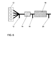
- an internal combustion engine 10 has an exhaust gas aftertreatment arrangement in an exhaust gas line, which has the following in the flow direction, a first lambda probe 12, which is designed to emit a continuous lambda signal, a pre-catalyst 14, a second lambda probe 16, which is used to emit a jump signal is formed, a NO x storing catalyst 18 and a NOx sensor 20.
- the exhaust-gas aftertreatment arrangement following on, a first exhaust bank 100 and a second exhaust bank 200, the lead 22 together and in a common NO x storage 18 open, which is a NO x sensor 20 downstream.
- the first exhaust bank 100 includes, seen in the flow direction, a first lambda probe 112 of the first exhaust bank 100, which is designed to emit a steady lambda signal, a precatalyst 114 of the first exhaust bank 100 and a second lambda probe 116 of the first exhaust bank 100, which is designed to emit a jump signal
- the second exhaust bank 200 includes, seen in the flow direction, a first lambda probe 212 of the second exhaust bank 200, which is designed to emit a steady lambda signal, a pre-catalyst 214 of the second exhaust bank 200 and a second lambda probe 216 of the second exhaust bank 200, which is designed to emit a jump signal ,
- Fig. 1 and 2 illustrate based on graphs for lambda values over time, a measurement of an oxygen storage capacity (OSC - O xygen- S torage- C apacity) taking advantage of a NO x regeneration of an internal combustion engine having a configuration according to Fig 6.
- horizontal axis 24 is time t
- vertical axis 26 is a lambda value
- vertical axis 28 is a probe voltage.
- a graph 30 shows a time course of lambda before the pre-catalyst 14.
- a graph 32 shows a probe voltage of the lambda probe 16 after the pre-catalyst 14.
- a graph 34 shows a probe voltage of the NO x sensor 20 after the NO x storage catalyst 18.
- a NO x regeneration is requested, wherein previously the internal combustion engine was operated in a lean operation with lambda >> 1.
- a lambda in the rich range (rich exhaust gas composition) of, for example, 0.8 to 0.9 is set for the NO x regeneration before the precatalyst 14.
- This phase is ended by changing the lambda to the NO x storage catalytic converter 18 from lean to rich, ie the probe voltage 34 increases abruptly.
- the OSC measurement thus takes place in the time interval t 1 -t 3 and the NO x regeneration in the time interval t 1 -t 2 .
- these two processes overlap in time or partially in parallel and take less time overall, as if both processes would run sequentially or separately.
- the lambda signals 32 and 34 are made plausible namely with respect to their dynamic behavior checked and with regard to the exchange of respective first and second lambda probes in a Two-bank system, as shown in Fig. 7, monitors what follows more closely is described.
- a jump from rich exhaust gas composition to lean exhaust gas composition takes place. This is used to test a dynamic behavior of the lambda probe 12 before the pre-catalyst 14.
- the dynamic measurement of the first lambda probe 12 is labeled 52.
- the gradient is used as delta O 2 / dt, delta voltage / dt or delta oxygen pump current / dt. For example, the gradient between the desired lambda values and the actually measured gradient of the lambda signal is compared. If the dynamic value falls below a predetermined threshold, errors are detected.
- the jump from rich exhaust gas composition to lean exhaust gas composition at time t 3 at the end of the OSC measurement 46 is utilized.
- the dynamic measurement of the second lambda probe 16 is labeled 54.
- the measurement and evaluation of the probe dynamics for example, analogous to the first lambda probe 12 before the pre-catalyst 14th
- the maximum gradient can also be used as the dynamic criterion which changes when you change from rich exhaust gas composition lean exhaust gas composition.
- an averaged gradient calculated from a minimum fat lambda value to a minimum lean lambda results.
- a rough plausibility check of the second lambda probe 16 after the precatalyst 14 in relation to the first lambda probe 12 before the precatalyst 14 takes place in the respective measuring phase "lean" in the time interval t 2 -t 3 or "fat” in the time interval t 1 -t 2 .
- After setting of rich mixture before the pre-catalyst 14 is checked after a corresponding Entprellzeit whether the lambda after the pre-catalyst 14 is also displayed in bold.
- a Release defined, resulting from the sub-approvals of the individual test functions such as catalyst testing, lambda testing, etc.
- a global Release defines the physical testing conditions of each partial test considered. Only when this release is given, the active measuring phase the lambda adjustment executed.
- Figs. 3, 4 and 5 illustrate a flow of monitoring for probe interchange between the first lambda probes 112, 212 upstream of the precatalysts 114, 214 and the second lambda probes 116, 216 after the pre-catalysts 114, 214 respectively of the two exhaust banks 100 and 200.
- Fig. 3 shows a temporal History of lambda values in an exhaust aftertreatment arrangement in State "i.O.”
- Fig. 4 shows a time course of lambda values at a Exhaust after-treatment arrangement in the state "exchanged second lambda probes 116, 216 after the pre-catalyst 114, 214 "and Fig.
- FIGS. 3, 4 and 5 shows a temporal History of lambda values in an exhaust aftertreatment device in the state "exchanged first lambda probes 112, 212 before the precatalyst 114, 214.
- the upper axbox in each case in FIGS. 3, 4 and 5 relates to the first exhaust gas bank 100 and the respective lower axbox relates to the second exhaust bank 200.
- Graph 130 shows a time course of Lambda according to the first lambda probe 112 before the pre-catalyst 114 for the first exhaust bank 100 and graph 132 shows a time profile of lambda according to the second lambda probe 116 after the pre-catalyst 114 for the first Exhaust bank 100.
- Graph 230 shows a time course of lambda according to the first lambda probe 212 before the pre-catalyst 214 for the second exhaust bank 200 and graph 232 shows a time course of lambda according to the second Lambda probe 216 after the pre-catalyst 214 for the second exhaust bank 200th
- the first lambda probes 112, 212 or the second lambda probes 116, 216 during installation or replacement be installed swapped.
- the lambda control parameters fit one Exhaust bank 100, 200 not to the measured lambda signal. This results Incorrect control interventions, misdiagnosis or emission deterioration May have consequences.
- An interchangeable detection is performed in parallel with the active lambda operation for the OSC measurement 46 (FIG. 2), as graphically illustrated in FIG.
- the active lambda adjustment for the catalyst diagnosis for the two exhaust banks 100 and 200 is requested offset in time.
- the time offset T1 is selected such that initially the lambda adjustment for the first exhaust bank 100 takes place and the lambda adjustment for the second exhaust bank 200 is only performed when the first bank 100 has already completed the probe jump test at t 2 or in the event of a fault there was sufficient time to expire the diagnosis in the first exhaust bank 100.
- This necessary time shift is, for example, fixed, in particular via a delta T, or the time shift is determined via models that take into account the OSC of the precatalyst 114, 214 as a function of gas flow rate, catalyst temperature. Either the lean-fat jump or the fat-lean jump of the probe signals 132, 232 or 130, 230 is evaluated.
- FIG. 4 illustrates how reversed second lambda probes 116, 216 affect and are detected downstream of pre-catalysts 114, 214.
- the second lambda probe 116 does not react after the pre-catalyst 114 for this exhaust bank 100, but the second lambda probe 216 jumps after the pre-catalyst 214 of the second exhaust bank 200, as indicated by arrow 58.
- FIG. 5 illustrates how reversed first lambda probes 112, 212 act and are detected before precatalyst 114, 214.
- the lambda desired value 30a before the pre-catalyst 114 of the first exhaust bank 100 and the lambda desired value 30b before the pre-catalyst 214 of the second exhaust bank 200 with the lambda actual value 130, 230 of the first lambda sensors 112, 212 before the pre-catalyst 114, 214 compared with actively requested adjustment.
- a lambda setpoint adjustment for the first exhaust gas bank 100 is output in the time interval t 1 -t 2 (for example, rich in fat: catalyst clearing out).
- the first lambda probe 112 (signal 130) before the primary catalytic converter 114 of the first exhaust gas bank 100 does not react to the adjustment, but the first lambda probe 212 before the primary catalytic converter 214 of the second exhaust gas bank 200 (signal 230).
- the fat adjustment is terminated via the lambda signal 132 (FIG. 3) after the precatalytic converter 114 of the first exhaust gas bank 100.
- the signal 230 of the first lambda probe 212 is displayed before Pre-catalyst 214 of the second exhaust bank 200 lean indicate, while the signal 130 of the first lambda probe 112 does not react before the pre-catalyst 114 of the first exhaust bank 100.
- the exact reverse behavior results at the time staggered lambda adjustments for the second exhaust bank 200 in the time intervals t 1 '-t 2 ' and t 2 '-t 3 '.
- test result for catalytic converter and lambda probes is set to "checked” for this case (cycle flag or Z_flag set). If the test result for the OSC value from step 66 is between the value for a very good catalyst and a defective catalyst (n.i.O.), so in at decision step 68, branch 74 "moderately aged> OSC> boundary cat” to step 76 "number x checks for Z_flag", where x is for example a Number is from 2 to 5, and it is thus a number of x corresponding number of Tests requested before the catalyst is considered tested.
- step 68 Is the test result for the OSC value from step 66 in the area of a defective catalyst (n.i.O.), then in decision step 68, branch 78 becomes "OSC ⁇ boundary cat" is selected to step 80 "number y tests for Z_flag", where y for example, a number from 6 to 10, and it will thus one of the number y corresponding Number of tests requested before the catalyst as tested applies to debounce the error.
Abstract
Description
- Fig. 1
- eine graphische Veranschaulichung einer Sauerstoffspeicherkapazität(OSC)-Messung eines Vorkatalysators bei Übergang von einer NOx-Regeneration in einen Magerbetrieb;
- Fig. 2
- eine graphische Veranschaulichung einer Kombination von Katalysatorund Lambdasonden-Diagnose;
- Fig. 3
- eine graphische Veranschaulichung einer Lambdasonden-Vertauschungserkennung für ein Zwei-Bank-Konzept bei korrekt angeschlossenen Lambdasonden;
- Fig. 4
- eine graphische Veranschaulichung einer Lambdasonden-Vertauschungserkennung für ein Zwei-Bank-Konzept bei vertauschten Lambdasonden nach den Katalysatoren der Abgasbänke;
- Fig. 5
- eine graphische Veranschaulichung einer Lambdasonden-Vertauschungserkennung für ein Zwei-Bank-Konzept bei vertauschten Lambdasonden vor den Katalysatoren der Abgasbänke;
- Fig. 6
- eine schematische Darstellung einer Brennkraftmaschine mit Vorkatalysator und NOx-Speicherkatalysator;
- Fig. 7
- eine schematische Darstellung einer Brennkraftmaschine mit zwei Abgasbänken, die jeweils einen Vorkatalysator mit jeweils stromauf und stromab angeordneten Lambdasonden aufweisen und
- Fig. 8
- ein schematisches Blockdiagramm eines Verfahrens mit reduzierter Diagnosezeit für eine aktive Katalysatordiagnose.
Claims (19)
- Verfahren zum Betreiben einer Brennkraftmaschine, insbesondere eines Kraftfahrzeuges, mit einer in einem Abgastrakt der Brennkraftmaschine angeordneten Abgasnachbehandlungsanordnung mit wenigstens einem Katalysator und einer stromauf des Katalysators angeordneten ersten Lambdasonde und einer stromab des Katalysators angeordneten zweiten Lambdasonde, wobei zur Bestimmung einer Sauerstoffspeicherfähigkeit des Katalysators in einem ersten Schritt (a) ein Lambdawert vor dem Katalysator aktiv auf einen Wert kleiner 1 verstellt wird, bis ein in dem Katalysator gespeicherter Sauerstoff vollständig ausgetragen ist, und anschließend in einem zweiten Schritt (b) der Lambdawert vor dem Katalysator aktiv auf einen Wert größer 1 verstellt wird, bis der Katalysator vollständig mit Sauerstoff beladen ist, wobei mittels einer Sauerstoffbilanzierung die Sauerstoffspeicherfähigkeit des Katalysators bestimmt wird, wobei die Abgasnachbehandlungsanordnung zusätzlich einen dem Katalysator nachgeordneten NOx-Speicherkatalysator aufweist, wobei unter vorbestimmten Bedingungen eine zeitlich begrenzte NOx-Regeneration des NOx-Speicherkatalysators durchgeführt wird,
dadurch gekennzeichnet, daß die NOx-Regeneration als erster Schritt (a) durchgeführt und nach Beendigung der NOx-Regeneration der zweite Schritt (b) durchgeführt wird. - Verfahren nach Anspruch 1, dadurch gekennzeichnet, daß der Katalysator ein Vorkatalysator oder ein Hauptkatalysator ist.
- Verfahren nach Anspruch 1, dadurch gekennzeichnet, daß gleichzeitig während der Bestimmung der Sauerstoffspeicherfähigkeit wenigstens ein Parameter der Lambdasonden bestimmt und aus dem Parameter eine Funktionsfähigkeit der Lambdasonden bestimmt wird.
- Verfahren nach Anspruch 3, dadurch gekennzeichnet, daß die Bestimmung wenigstens eines Parameters der Lambdasonden eine Plausibilitätsprüfung umfaßt, wobei im ersten Schritt (a) und/oder im zweiten Schritt (b) geprüft wird, ob erste und zweite Lambdasonde gleichzeitig die erwartete fette bzw. magere Abgaszusammensetzung anzeigen.
- Verfahren nach Anspruch 4, dadurch gekennzeichnet, daß in dem Fall, daß die Plausibilitätsprüfung eine Plausibilitätsverletzung ergibt, d.h. eine unterschiedliche Anzeige der Abgaszusammensetzung vor und nach dem Katalysator durch der beiden Lambdasonden, wird bestimmt, ob die erste oder zweite Lambdasonde defekt ist.
- Verfahren nach Anspruch 5, dadurch gekennzeichnet, daß zur Bestimmung der fehlerhaften Lambdasonde eine vorbestimmte Betriebsart der Brennkraftmaschine, insbesondere ein Homogen-Lambda-1-Betrieb, eingestellt wird.
- Verfahren nach wenigstens einem der vorhergehenden Ansprüche, dadurch gekennzeichnet, daß für eine Abgasnachbehandlungsanordnung mit zwei parallel im Abgasstrang angeordneten Katalysatoren die Bestimmung wenigstens eines Parameters der Lambdasonden eine Vertauschung der jeweiligen ersten Lambdasonden vor den Katalysatoren und/oder der jeweiligen zweiten Lambdasonden nach den Katalysatoren umfaßt, wobei der Schritt (a) für einen zweiten der parallelen Katalysatoren um eine vorbestimmte Zeit versetzt später ausgeführt wird, als für den entsprechend anderen ersten der beiden parallelen Katalysatoren, wobei eine Vertauschung des Anschlusses der beiden ersten Lambdasonden der beiden Katalysatoren bestimmt wird, wenn für eine vorbestimmte Anzahl von Zyklen der Schritte (a) und (b) die erste Lambdasonde des zweiten Katalysators eine Zustandsänderung des Abgases vor der ersten Lambdasonde des ersten Katalysators anzeigt, und wobei eine Vertauschung des Anschlusses der beiden zweiten Lambdasonden der beiden Katalysatoren bestimmt wird, wenn für eine vorbestimmte Anzahl von Zyklen der Schritte (a) und (b)die zweite Lambdasonde des zweiten Katalysators eine Zustandsänderung des Abgases vor der zweiten Lambdasonde des ersten Katalysators anzeigt.
- Verfahren nach Anspruch 7, dadurch gekennzeichnet, daß die Zustandsänderung des Abgases ein Sprung von magerer Abgaszusammensetzung zu fetter Abgaszusammensetzung oder ein Sprung von fetter Abgaszusammensetzung zu magerer Abgaszusammensetzung ist.
- Verfahren nach wenigstens einem der vorhergehenden Ansprüche, dadurch gekennzeichnet, daß die Bestimmung wenigstens eines Parameters der Lambdasonden ein Dynamikverhalten der Lambdasonden umfaßt, wobei ein Gradient der zeitliche Änderung eines Ausgangssignals der Lambdasonden bestimmt wird und eine fehlerhafte Lambdasonde bestimmt wird, wenn der Gradient kleiner als ein vorbestimmter Wert ist.
- Verfahren nach Anspruch 9, dadurch gekennzeichnet, daß der Gradient der zeitliche Änderung beim Übergang von fetter Abgaszusammensetzung zu magerer Abgaszusammensetzung am Ende von Schritt (b) bestimmt wird.
- Verfahren nach Anspruch 9 oder 10, dadurch gekennzeichnet, daß ein maximaler Gradient oder ein gemittelter Gradient bestimmt und mit einem entsprechenden, vorbestimmten Wert verglichen wird.
- Verfahren nach wenigstens einem der vorhergehenden Ansprüche, dadurch gekennzeichnet, daß in Abhängigkeit vom Ergebnis der Bestimmung der Sauerstoffspeicherfähigkeit weitere Prüfzyklen angefordert werden.
- Verfahren nach Anspruch 12, dadurch gekennzeichnet, daß für den Fall, daß die Sauerstoffspeicherfähigkeit einen Wert im Bereich eines frischen Katalysators ergibt und die Lambdasonden als funktionsfähig erkannt worden sind, werden für ein vorbestimmtes Zeitintervall, insbesondere bis zum nächsten Neustart der Brennkraftmaschine, keine weiteren Prüfzyklen angefordert.
- Verfahren nach Anspruch 12 oder 13, dadurch gekennzeichnet, daß für den Fall, daß die Sauerstoffspeicherfähigkeit einen Wert im Bereich zwischen einem frischen Katalysator und einem defekten Katalysator ergibt, eine vorbestimmte erste Anzahl, insbesondere 2 bis 5, von weiteren Prüfzyklen angefordert wird.
- Verfahren nach einem der Ansprüche 12 bis 14, dadurch gekennzeichnet, daß für den Fall, daß die Sauerstoffspeicherfähigkeit einen Wert im Bereich eines defekten Katalysators ergibt, eine vorbestimmte zweite Anzahl, insbesondere 6 bis 10, von weiteren Prüfzyklen angefordert wird.
- Verfahren nach Anspruch 14 und 15, dadurch gekennzeichnet, daß die erste Anzahl von weiteren Prüfzyklen kleiner ist als die zweite Anzahl von weiteren Prüfzyklen.
- Verfahren nach wenigstens einem der vorhergehenden Ansprüche, dadurch gekennzeichnet, daß im ersten Schritt (a) ein Lambdawert im Bereich von 0,95 bis 0,98 oder kleiner eingestellt wird.
- Verfahren nach wenigstens einem der vorhergehenden Ansprüche, dadurch gekennzeichnet, daß im zweiten Schritt (b) ein Lambdawert im Bereich von 1,02 bis 1,05, insbesondere 1,03, eingestellt wird.
- Verfahren nach wenigstens einem der vorhergehenden Ansprüche, dadurch gekennzeichnet, daß die Bestimmung wenigstens eines Parameters der Lambdasonden eine Prüfung einer Magerspannung und/oder einer Fettspannung der ersten und/oder zweiten Lambdasonde umfaßt.
Applications Claiming Priority (2)
| Application Number | Priority Date | Filing Date | Title |
|---|---|---|---|
| DE10331331A DE10331331B4 (de) | 2003-07-10 | 2003-07-10 | Verfahren zum Betreiben einer Brennkraftmaschine |
| DE10331331 | 2003-07-10 |
Publications (2)
| Publication Number | Publication Date |
|---|---|
| EP1496225A2 true EP1496225A2 (de) | 2005-01-12 |
| EP1496225A3 EP1496225A3 (de) | 2007-05-30 |
Family
ID=33441714
Family Applications (1)
| Application Number | Title | Priority Date | Filing Date |
|---|---|---|---|
| EP04102669A Withdrawn EP1496225A3 (de) | 2003-07-10 | 2004-06-14 | Verfahren zum Betreiben einer Brennkraftmaschine |
Country Status (2)
| Country | Link |
|---|---|
| EP (1) | EP1496225A3 (de) |
| DE (1) | DE10331331B4 (de) |
Cited By (3)
| Publication number | Priority date | Publication date | Assignee | Title |
|---|---|---|---|---|
| WO2007128593A1 (de) * | 2006-05-05 | 2007-11-15 | Continental Automotive Gmbh | Verfahren und vorrichtung zur diagnose der wirksamkeit eines abgaskatalysators |
| WO2009089977A1 (de) * | 2008-01-14 | 2009-07-23 | Robert Bosch Gmbh | Verfahren und steuergerät zur überprüfung eines abgasnachbehandlungssystems eines verbrennungsmotors |
| EP1857647A4 (de) * | 2005-01-31 | 2015-03-25 | Isuzu Motors Ltd | Verfahren zur erhöhung der temperatur einer abgasreinigungsvorrichtung und abgasreinigungssystem |
Families Citing this family (3)
| Publication number | Priority date | Publication date | Assignee | Title |
|---|---|---|---|---|
| DE102005034880B4 (de) * | 2005-07-26 | 2007-06-06 | Siemens Ag | Verfahren und Vorrichtung zur Diagnose einer Abgasreinigungsanlage |
| DE102017216997A1 (de) | 2017-09-26 | 2019-03-28 | Bayerische Motoren Werke Aktiengesellschaft | Katalysator mit OBD-System |
| DE102017216998A1 (de) | 2017-09-26 | 2019-03-28 | Bayerische Motoren Werke Aktiengesellschaft | Katalysator mit OBD-System |
Citations (10)
| Publication number | Priority date | Publication date | Assignee | Title |
|---|---|---|---|---|
| DE2328459A1 (de) | 1973-01-31 | 1975-01-02 | Bosch Gmbh Robert | Einrichtung zur ueberwachung von katalytischen reaktoren in abgasentgiftungsanlagen von brennkraftmaschinen |
| DE4112478A1 (de) | 1991-04-17 | 1992-10-22 | Bosch Gmbh Robert | Verfahren und vorrichtung zum beurteilen des alterungszustandes eines katalysators |
| EP0897054A1 (de) | 1997-08-11 | 1999-02-17 | Daimler-Benz Aktiengesellschaft | Verfahren zur Vertauschprüfung von Lambdasonden |
| DE19801626A1 (de) | 1998-01-17 | 1999-07-22 | Bosch Gmbh Robert | Diagnose eines NOx-Speicherkatalysators beim Betrieb von Verbrennungsmotoren |
| DE19803828A1 (de) | 1998-01-31 | 1999-08-05 | Bosch Gmbh Robert | Verfahren und Vorrichtung zur Beurteilung der Konvertierungsfähigkeit eines Katalysators |
| DE19953601A1 (de) | 1999-11-08 | 2001-05-23 | Siemens Ag | Verfahren zum Überprüfen eines Abgaskatalysators einer Brennkraftmaschine |
| DE10026213A1 (de) | 2000-05-26 | 2001-11-29 | Volkswagen Ag | Verfahren zum Konfigurieren einer Mehrzahl von Lambdasonden eines Verbrennungsmotors |
| DE10017931A1 (de) | 2000-04-11 | 2001-12-06 | Siemens Ag | Verfahren zur Diagnose einer Abgasreinigungsanlage einer lambdageregelten Brennkraftmaschine |
| DE10015330A1 (de) | 2000-03-28 | 2002-02-21 | Volkswagen Ag | Verfahren und Vorrichtung zur Abgasreinigung |
| DE10117244A1 (de) | 2001-04-06 | 2002-11-07 | Audi Ag | Verfahren zur Erkennung vertauscht angeschlossener O¶2¶-Sensoren |
Family Cites Families (9)
| Publication number | Priority date | Publication date | Assignee | Title |
|---|---|---|---|---|
| DE59306790D1 (de) * | 1993-03-15 | 1997-07-24 | Siemens Ag | Verfahren zur Überprüfung von Lambdasonden |
| JP2858288B2 (ja) * | 1993-09-02 | 1999-02-17 | 株式会社ユニシアジェックス | 内燃機関の空燃比制御装置における自己診断装置 |
| JP3412290B2 (ja) * | 1994-09-29 | 2003-06-03 | 株式会社デンソー | 排気ガス浄化用触媒劣化検査装置 |
| JP3498817B2 (ja) * | 1995-06-14 | 2004-02-23 | 株式会社デンソー | 内燃機関の排気系故障診断装置 |
| DE19646008B4 (de) * | 1995-11-08 | 2005-03-17 | Denso Corp., Kariya | Abnormalitätserfassungsvorrichtung für ein Luft-Kraftstoffverhältnis-Steuerungssystem |
| DE19706382C2 (de) * | 1997-02-19 | 2003-03-06 | Daimler Chrysler Ag | Verfahren zur Prüfung auf korrekt angeschlossene Lambda-Sonden |
| DE19844178A1 (de) * | 1998-09-25 | 2000-03-30 | Bosch Gmbh Robert | Katalysatordiagnoseverfahren |
| DE19923498A1 (de) * | 1999-05-21 | 2000-11-23 | Volkswagen Ag | Verfahren zur Steuerung einer Regeneration eines NOx-Speicherkatalysators |
| DE10115956A1 (de) * | 2000-04-07 | 2001-10-11 | Volkswagen Ag | Mehrflutige Abgasanlage eines Mehrzylindermotors und Verfahren zur Regelung eines Luft-Kraftstoff-Verhältnisses |
-
2003
- 2003-07-10 DE DE10331331A patent/DE10331331B4/de not_active Expired - Fee Related
-
2004
- 2004-06-14 EP EP04102669A patent/EP1496225A3/de not_active Withdrawn
Patent Citations (10)
| Publication number | Priority date | Publication date | Assignee | Title |
|---|---|---|---|---|
| DE2328459A1 (de) | 1973-01-31 | 1975-01-02 | Bosch Gmbh Robert | Einrichtung zur ueberwachung von katalytischen reaktoren in abgasentgiftungsanlagen von brennkraftmaschinen |
| DE4112478A1 (de) | 1991-04-17 | 1992-10-22 | Bosch Gmbh Robert | Verfahren und vorrichtung zum beurteilen des alterungszustandes eines katalysators |
| EP0897054A1 (de) | 1997-08-11 | 1999-02-17 | Daimler-Benz Aktiengesellschaft | Verfahren zur Vertauschprüfung von Lambdasonden |
| DE19801626A1 (de) | 1998-01-17 | 1999-07-22 | Bosch Gmbh Robert | Diagnose eines NOx-Speicherkatalysators beim Betrieb von Verbrennungsmotoren |
| DE19803828A1 (de) | 1998-01-31 | 1999-08-05 | Bosch Gmbh Robert | Verfahren und Vorrichtung zur Beurteilung der Konvertierungsfähigkeit eines Katalysators |
| DE19953601A1 (de) | 1999-11-08 | 2001-05-23 | Siemens Ag | Verfahren zum Überprüfen eines Abgaskatalysators einer Brennkraftmaschine |
| DE10015330A1 (de) | 2000-03-28 | 2002-02-21 | Volkswagen Ag | Verfahren und Vorrichtung zur Abgasreinigung |
| DE10017931A1 (de) | 2000-04-11 | 2001-12-06 | Siemens Ag | Verfahren zur Diagnose einer Abgasreinigungsanlage einer lambdageregelten Brennkraftmaschine |
| DE10026213A1 (de) | 2000-05-26 | 2001-11-29 | Volkswagen Ag | Verfahren zum Konfigurieren einer Mehrzahl von Lambdasonden eines Verbrennungsmotors |
| DE10117244A1 (de) | 2001-04-06 | 2002-11-07 | Audi Ag | Verfahren zur Erkennung vertauscht angeschlossener O¶2¶-Sensoren |
Cited By (4)
| Publication number | Priority date | Publication date | Assignee | Title |
|---|---|---|---|---|
| EP1857647A4 (de) * | 2005-01-31 | 2015-03-25 | Isuzu Motors Ltd | Verfahren zur erhöhung der temperatur einer abgasreinigungsvorrichtung und abgasreinigungssystem |
| WO2007128593A1 (de) * | 2006-05-05 | 2007-11-15 | Continental Automotive Gmbh | Verfahren und vorrichtung zur diagnose der wirksamkeit eines abgaskatalysators |
| US8112984B2 (en) | 2006-05-05 | 2012-02-14 | Continental Automotive Gmbh | Method and device for the diagnosis of the effectiveness of a catalytic converter |
| WO2009089977A1 (de) * | 2008-01-14 | 2009-07-23 | Robert Bosch Gmbh | Verfahren und steuergerät zur überprüfung eines abgasnachbehandlungssystems eines verbrennungsmotors |
Also Published As
| Publication number | Publication date |
|---|---|
| EP1496225A3 (de) | 2007-05-30 |
| DE10331331A1 (de) | 2005-02-17 |
| DE10331331B4 (de) | 2012-03-01 |
Similar Documents
| Publication | Publication Date | Title |
|---|---|---|
| EP1131544B1 (de) | ÜBERWACHUNGSVERFAHREN FÜR NOx SPEICHERKATALYSATOREN UND ABGASREINIGUNGSVORRICHTUNG ZUR DURCHFÜHRUNG DIESES VERFAHRENS | |
| EP1228301B1 (de) | Verfahren zum überprüfen eines abgaskatalysators einer brennkraftmaschine | |
| EP1060003B1 (de) | Steuerung eines nox-absorber-katalysators | |
| EP1097299B1 (de) | VERFAHREN ZUR ÜBERPRÜFUNG DES WIRKUNGSGRADES EINES NOx-SPEICHERKATALYSATORS | |
| DE102008038677B4 (de) | Verfahren und Vorrichtung zum Diagnostizieren eines Abgaskatalysators | |
| EP1192340B1 (de) | Verfahren zum überprüfen eines dreiwege-abgaskatalysators einer brennkraftmaschine | |
| DE19828929A1 (de) | Verfahren zur Überprüfung des Dynamikverhaltens eines Meßaufnehmers im Abgastrakt einer Brennkraftmaschine | |
| DE10331334B4 (de) | Verfahren zum Betreiben einer Brennkraftmaschine | |
| WO2004059152A1 (de) | Verfahren und vorrichtung zur diagnose der dynamischen eigenschaften einer zur zylinderindividuellen lambdaregelung verwendeten lambdasonde | |
| EP2238321B1 (de) | Verfahren und steuergerät zur überprüfung eines abgasnachbehandlungssystems eines verbrennungsmotors | |
| DE10331331B4 (de) | Verfahren zum Betreiben einer Brennkraftmaschine | |
| DE102016210143B4 (de) | Verfahren zur Ermittlung eines Alterungszustands eines NOx-Speicherkatalysators einer Abgasnachbehandlungsanlage eines für einen Magerbetrieb ausgelegten Verbrennungsmotors sowie Steuerungseinrichtung | |
| DE10331333B4 (de) | Verfahren zum Betreiben einer Brennkraftmaschine | |
| WO2020143968A1 (de) | Verfahren zur überwachung von sensorsignalen und quantitative ermittlung des stöchiometrischen kraftstoff-luftverhältnisses des gefahrenen kraftstoffs mittels injektortest und katalysatordiagnose in einem fahrzeug | |
| DE102006002257B4 (de) | Verfahren und Vorrichtung zum Betreiben eines Abgaskatalysators einer Brennkraftmaschine | |
| EP1143131A2 (de) | Mehrflutige Abgasanlage und Verfahren zur Regelung eines Luft-Kraftstoff-Verhältnisses und Steuerung einer NOx-Regeneration eines NOx-Speicherkatalysators | |
| EP1422398A1 (de) | Verfahren zur Diagnose der Funktionsfähigkeit einer Abgas-Katalysatoreinheit | |
| DE102014200360A1 (de) | Elektronische Steuereinrichtung zur Erkennung von Gemischunterschieden in einer Brennkraftmaschine | |
| WO2004053307A1 (de) | Verfahren und vorrichtung zur diagnose von katalysatoreinheiten | |
| DE102004006992B4 (de) | Diagnoseverfahren zum Bestimmen eines Zustandes eines Katalysatorsystems | |
| WO2009043737A1 (de) | Verfahren zur ermittlung der dynamischen eigenschaften eines abgassensors einer brennkraftmaschine | |
| DE10153769B4 (de) | Verfahren und Einrichtung zur Überwachung des Schädigungsgrades eines Katalysators | |
| DE102006053125A1 (de) | Verfahren und Steuergerät zur Diagnose eines Katalysatorsystems eines Verbrennungsmotors | |
| EP1434049B1 (de) | Verfahren und Vorrichtung zur Überwachung des NOx-Signals eines NOx-Sensors | |
| DE102020210551B4 (de) | Verfahren und Vorrichtung zur Überwachung und zur Steuerung einer Sauerstoffbeladung eines Abgaskatalysators eines Abgastrakts einer Brennkraftmaschine |
Legal Events
| Date | Code | Title | Description |
|---|---|---|---|
| PUAI | Public reference made under article 153(3) epc to a published international application that has entered the european phase |
Free format text: ORIGINAL CODE: 0009012 |
|
| AK | Designated contracting states |
Kind code of ref document: A2 Designated state(s): AT BE BG CH CY CZ DE DK EE ES FI FR GB GR HU IE IT LI LU MC NL PL PT RO SE SI SK TR |
|
| AX | Request for extension of the european patent |
Extension state: AL HR LT LV MK |
|
| PUAL | Search report despatched |
Free format text: ORIGINAL CODE: 0009013 |
|
| AK | Designated contracting states |
Kind code of ref document: A3 Designated state(s): AT BE BG CH CY CZ DE DK EE ES FI FR GB GR HU IE IT LI LU MC NL PL PT RO SE SI SK TR |
|
| AX | Request for extension of the european patent |
Extension state: AL HR LT LV MK |
|
| 17P | Request for examination filed |
Effective date: 20071130 |
|
| AKX | Designation fees paid |
Designated state(s): AT BE BG CH CY CZ DE DK EE ES FI FR GB GR HU IE IT LI LU MC NL PL PT RO SE SI SK TR |
|
| 17Q | First examination report despatched |
Effective date: 20080317 |
|
| R17C | First examination report despatched (corrected) |
Effective date: 20080523 |
|
| RAP1 | Party data changed (applicant data changed or rights of an application transferred) |
Owner name: VOLKSWAGEN AKTIENGESELLSCHAFT |
|
| STAA | Information on the status of an ep patent application or granted ep patent |
Free format text: STATUS: THE APPLICATION IS DEEMED TO BE WITHDRAWN |
|
| 18D | Application deemed to be withdrawn |
Effective date: 20140103 |