EP1496225A2 - Method for controlling an internal combustion engine - Google Patents
Method for controlling an internal combustion engine Download PDFInfo
- Publication number
- EP1496225A2 EP1496225A2 EP04102669A EP04102669A EP1496225A2 EP 1496225 A2 EP1496225 A2 EP 1496225A2 EP 04102669 A EP04102669 A EP 04102669A EP 04102669 A EP04102669 A EP 04102669A EP 1496225 A2 EP1496225 A2 EP 1496225A2
- Authority
- EP
- European Patent Office
- Prior art keywords
- lambda
- catalyst
- exhaust gas
- probe
- value
- Prior art date
- Legal status (The legal status is an assumption and is not a legal conclusion. Google has not performed a legal analysis and makes no representation as to the accuracy of the status listed.)
- Withdrawn
Links
Images


Classifications
-
- F—MECHANICAL ENGINEERING; LIGHTING; HEATING; WEAPONS; BLASTING
- F02—COMBUSTION ENGINES; HOT-GAS OR COMBUSTION-PRODUCT ENGINE PLANTS
- F02D—CONTROLLING COMBUSTION ENGINES
- F02D41/00—Electrical control of supply of combustible mixture or its constituents
- F02D41/02—Circuit arrangements for generating control signals
- F02D41/14—Introducing closed-loop corrections
- F02D41/1438—Introducing closed-loop corrections using means for determining characteristics of the combustion gases; Sensors therefor
- F02D41/1493—Details
- F02D41/1495—Detection of abnormalities in the air/fuel ratio feedback system
-
- F—MECHANICAL ENGINEERING; LIGHTING; HEATING; WEAPONS; BLASTING
- F01—MACHINES OR ENGINES IN GENERAL; ENGINE PLANTS IN GENERAL; STEAM ENGINES
- F01N—GAS-FLOW SILENCERS OR EXHAUST APPARATUS FOR MACHINES OR ENGINES IN GENERAL; GAS-FLOW SILENCERS OR EXHAUST APPARATUS FOR INTERNAL COMBUSTION ENGINES
- F01N11/00—Monitoring or diagnostic devices for exhaust-gas treatment apparatus, e.g. for catalytic activity
- F01N11/007—Monitoring or diagnostic devices for exhaust-gas treatment apparatus, e.g. for catalytic activity the diagnostic devices measuring oxygen or air concentration downstream of the exhaust apparatus
-
- F—MECHANICAL ENGINEERING; LIGHTING; HEATING; WEAPONS; BLASTING
- F01—MACHINES OR ENGINES IN GENERAL; ENGINE PLANTS IN GENERAL; STEAM ENGINES
- F01N—GAS-FLOW SILENCERS OR EXHAUST APPARATUS FOR MACHINES OR ENGINES IN GENERAL; GAS-FLOW SILENCERS OR EXHAUST APPARATUS FOR INTERNAL COMBUSTION ENGINES
- F01N13/00—Exhaust or silencing apparatus characterised by constructional features ; Exhaust or silencing apparatus, or parts thereof, having pertinent characteristics not provided for in, or of interest apart from, groups F01N1/00 - F01N5/00, F01N9/00, F01N11/00
- F01N13/011—Exhaust or silencing apparatus characterised by constructional features ; Exhaust or silencing apparatus, or parts thereof, having pertinent characteristics not provided for in, or of interest apart from, groups F01N1/00 - F01N5/00, F01N9/00, F01N11/00 having two or more purifying devices arranged in parallel
-
- F—MECHANICAL ENGINEERING; LIGHTING; HEATING; WEAPONS; BLASTING
- F01—MACHINES OR ENGINES IN GENERAL; ENGINE PLANTS IN GENERAL; STEAM ENGINES
- F01N—GAS-FLOW SILENCERS OR EXHAUST APPARATUS FOR MACHINES OR ENGINES IN GENERAL; GAS-FLOW SILENCERS OR EXHAUST APPARATUS FOR INTERNAL COMBUSTION ENGINES
- F01N3/00—Exhaust or silencing apparatus having means for purifying, rendering innocuous, or otherwise treating exhaust
- F01N3/08—Exhaust or silencing apparatus having means for purifying, rendering innocuous, or otherwise treating exhaust for rendering innocuous
- F01N3/0807—Exhaust or silencing apparatus having means for purifying, rendering innocuous, or otherwise treating exhaust for rendering innocuous by using absorbents or adsorbents
- F01N3/0814—Exhaust or silencing apparatus having means for purifying, rendering innocuous, or otherwise treating exhaust for rendering innocuous by using absorbents or adsorbents combined with catalytic converters, e.g. NOx absorption/storage reduction catalysts
-
- F—MECHANICAL ENGINEERING; LIGHTING; HEATING; WEAPONS; BLASTING
- F01—MACHINES OR ENGINES IN GENERAL; ENGINE PLANTS IN GENERAL; STEAM ENGINES
- F01N—GAS-FLOW SILENCERS OR EXHAUST APPARATUS FOR MACHINES OR ENGINES IN GENERAL; GAS-FLOW SILENCERS OR EXHAUST APPARATUS FOR INTERNAL COMBUSTION ENGINES
- F01N3/00—Exhaust or silencing apparatus having means for purifying, rendering innocuous, or otherwise treating exhaust
- F01N3/08—Exhaust or silencing apparatus having means for purifying, rendering innocuous, or otherwise treating exhaust for rendering innocuous
- F01N3/0807—Exhaust or silencing apparatus having means for purifying, rendering innocuous, or otherwise treating exhaust for rendering innocuous by using absorbents or adsorbents
- F01N3/0828—Exhaust or silencing apparatus having means for purifying, rendering innocuous, or otherwise treating exhaust for rendering innocuous by using absorbents or adsorbents characterised by the absorbed or adsorbed substances
- F01N3/0842—Nitrogen oxides
-
- F—MECHANICAL ENGINEERING; LIGHTING; HEATING; WEAPONS; BLASTING
- F01—MACHINES OR ENGINES IN GENERAL; ENGINE PLANTS IN GENERAL; STEAM ENGINES
- F01N—GAS-FLOW SILENCERS OR EXHAUST APPARATUS FOR MACHINES OR ENGINES IN GENERAL; GAS-FLOW SILENCERS OR EXHAUST APPARATUS FOR INTERNAL COMBUSTION ENGINES
- F01N3/00—Exhaust or silencing apparatus having means for purifying, rendering innocuous, or otherwise treating exhaust
- F01N3/08—Exhaust or silencing apparatus having means for purifying, rendering innocuous, or otherwise treating exhaust for rendering innocuous
- F01N3/0807—Exhaust or silencing apparatus having means for purifying, rendering innocuous, or otherwise treating exhaust for rendering innocuous by using absorbents or adsorbents
- F01N3/0871—Regulation of absorbents or adsorbents, e.g. purging
-
- F—MECHANICAL ENGINEERING; LIGHTING; HEATING; WEAPONS; BLASTING
- F02—COMBUSTION ENGINES; HOT-GAS OR COMBUSTION-PRODUCT ENGINE PLANTS
- F02D—CONTROLLING COMBUSTION ENGINES
- F02D41/00—Electrical control of supply of combustible mixture or its constituents
- F02D41/02—Circuit arrangements for generating control signals
- F02D41/021—Introducing corrections for particular conditions exterior to the engine
- F02D41/0235—Introducing corrections for particular conditions exterior to the engine in relation with the state of the exhaust gas treating apparatus
- F02D41/027—Introducing corrections for particular conditions exterior to the engine in relation with the state of the exhaust gas treating apparatus to purge or regenerate the exhaust gas treating apparatus
- F02D41/0275—Introducing corrections for particular conditions exterior to the engine in relation with the state of the exhaust gas treating apparatus to purge or regenerate the exhaust gas treating apparatus the exhaust gas treating apparatus being a NOx trap or adsorbent
-
- F—MECHANICAL ENGINEERING; LIGHTING; HEATING; WEAPONS; BLASTING
- F01—MACHINES OR ENGINES IN GENERAL; ENGINE PLANTS IN GENERAL; STEAM ENGINES
- F01N—GAS-FLOW SILENCERS OR EXHAUST APPARATUS FOR MACHINES OR ENGINES IN GENERAL; GAS-FLOW SILENCERS OR EXHAUST APPARATUS FOR INTERNAL COMBUSTION ENGINES
- F01N2430/00—Influencing exhaust purification, e.g. starting of catalytic reaction, filter regeneration, or the like, by controlling engine operating characteristics
- F01N2430/06—Influencing exhaust purification, e.g. starting of catalytic reaction, filter regeneration, or the like, by controlling engine operating characteristics by varying fuel-air ratio, e.g. by enriching fuel-air mixture
-
- F—MECHANICAL ENGINEERING; LIGHTING; HEATING; WEAPONS; BLASTING
- F01—MACHINES OR ENGINES IN GENERAL; ENGINE PLANTS IN GENERAL; STEAM ENGINES
- F01N—GAS-FLOW SILENCERS OR EXHAUST APPARATUS FOR MACHINES OR ENGINES IN GENERAL; GAS-FLOW SILENCERS OR EXHAUST APPARATUS FOR INTERNAL COMBUSTION ENGINES
- F01N2560/00—Exhaust systems with means for detecting or measuring exhaust gas components or characteristics
- F01N2560/02—Exhaust systems with means for detecting or measuring exhaust gas components or characteristics the means being an exhaust gas sensor
- F01N2560/025—Exhaust systems with means for detecting or measuring exhaust gas components or characteristics the means being an exhaust gas sensor for measuring or detecting O2, e.g. lambda sensors
-
- F—MECHANICAL ENGINEERING; LIGHTING; HEATING; WEAPONS; BLASTING
- F01—MACHINES OR ENGINES IN GENERAL; ENGINE PLANTS IN GENERAL; STEAM ENGINES
- F01N—GAS-FLOW SILENCERS OR EXHAUST APPARATUS FOR MACHINES OR ENGINES IN GENERAL; GAS-FLOW SILENCERS OR EXHAUST APPARATUS FOR INTERNAL COMBUSTION ENGINES
- F01N2560/00—Exhaust systems with means for detecting or measuring exhaust gas components or characteristics
- F01N2560/02—Exhaust systems with means for detecting or measuring exhaust gas components or characteristics the means being an exhaust gas sensor
- F01N2560/026—Exhaust systems with means for detecting or measuring exhaust gas components or characteristics the means being an exhaust gas sensor for measuring or detecting NOx
-
- F—MECHANICAL ENGINEERING; LIGHTING; HEATING; WEAPONS; BLASTING
- F02—COMBUSTION ENGINES; HOT-GAS OR COMBUSTION-PRODUCT ENGINE PLANTS
- F02D—CONTROLLING COMBUSTION ENGINES
- F02D2200/00—Input parameters for engine control
- F02D2200/02—Input parameters for engine control the parameters being related to the engine
- F02D2200/08—Exhaust gas treatment apparatus parameters
- F02D2200/0816—Oxygen storage capacity
-
- Y—GENERAL TAGGING OF NEW TECHNOLOGICAL DEVELOPMENTS; GENERAL TAGGING OF CROSS-SECTIONAL TECHNOLOGIES SPANNING OVER SEVERAL SECTIONS OF THE IPC; TECHNICAL SUBJECTS COVERED BY FORMER USPC CROSS-REFERENCE ART COLLECTIONS [XRACs] AND DIGESTS
- Y02—TECHNOLOGIES OR APPLICATIONS FOR MITIGATION OR ADAPTATION AGAINST CLIMATE CHANGE
- Y02T—CLIMATE CHANGE MITIGATION TECHNOLOGIES RELATED TO TRANSPORTATION
- Y02T10/00—Road transport of goods or passengers
- Y02T10/10—Internal combustion engine [ICE] based vehicles
- Y02T10/40—Engine management systems
Definitions
- the invention relates to a method for operating an internal combustion engine, in particular a motor vehicle, having an arranged in an exhaust tract of the internal combustion engine exhaust aftertreatment arrangement with at least one catalyst and upstream of the catalyst arranged first lambda probe and a downstream of the catalyst arranged second lambda probe, wherein for determining an oxygen storage capacity of Catalyst in a first step (a) a lambda value before the catalyst is actively adjusted to a value less than 1, until an oxygen stored in the catalyst is completely discharged, and then in a second step (b) the lambda value before the catalyst active on a Value greater than 1 is adjusted until the catalyst is completely laden with oxygen, wherein the oxygen storage capacity of the catalyst is determined by means of an oxygen balance, wherein the exhaust aftertreatment arrangement additionally a The catalyst downstream of the NOx storage catalytic converter, wherein under predetermined conditions, a time-limited NO x regeneration of the NO x storage catalytic converter is carried out according to the preamble of claim 1.
- the OSC also has a light-off and conversion behavior of the catalyst correlates.
- a rich lambda value for example 0.95 to 0.98 an oxygen possibly stored in the catalyst and then by setting a lambda value of, for example, 1.02 to 1.05 with a lean, oxygen-rich exhaust gas refilled with oxygen.
- the OSC is measured by oxygen balancing.
- the emptying and filling the catalyst with oxygen is about a jump of a Output signal of the catalytic converter downstream lambda probe into the grease or destined and controlled.
- EP 0 897 054 A1 discloses a method for permutation testing of lambda probes known.
- a multi-cylinder internal combustion engine with at least two separate exhaust pipes, each with a catalyst and at least each A lambda probe per exhaust pipe is used during a test period that is at least corresponds to the reaction time or switching time of the lambda probe, air by means of a Air source individually at least one exhaust pipe via at least one air connection fed in front of the lambda probe.
- a thereby changed exhaust gas value is quickly and clearly from the lambda probe assigned to the exhaust system identified. If the expected signal is not from the exhaust line assigned Lambda probe emanates, a permutation of the lambda probes detected become.
- From DE 101 17 244 A1 discloses a method for detecting reversed connected oxygen sensors, which are arranged in the exhaust line of an internal combustion engine one behind the other and connected to a control device for the fuel injection known. During a test period, the fuel injection is switched off or the air-fuel ratio changed and measured the reaction times until the occurrence of the resulting signal change in the O 2 sensors and evaluated.
- the invention is based on the object, a method of o.g. Type regarding diagnosis times and diagnostic frequency for the exhaust aftertreatment device improve.
- the NO x regeneration is determined as the first step (a) and after completion of the NO x regeneration the second step (b) is carried out.
- the catalyst is a precatalyst or a main catalyst.
- the determination of at least one parameter of the lambda probes comprises, for example a plausibility check, wherein in the first step (a) and / or in the second step (b) is checked whether the first and second lambda probe simultaneously indicate expected rich or lean exhaust gas composition.
- the plausibility check results in a plausibility violation, i. a different one Display of the exhaust gas composition before and after the catalyst by of the two lambda probes, it is determined whether the first or second lambda probe is defective.
- determining the faulty lambda probe is expediently a predetermined mode of operation of the internal combustion engine, in particular a Homogeneous Lambda 1 operation, discontinued.
- Catalysts comprise the determination of at least one parameter the lambda probes, for example, a permutation of the respective first Lambda sensors in front of the catalysts and / or the respective second lambda probes according to the catalysts, wherein step (a) is for a second of the parallel Catalysts offset by a predetermined time later executed as for the corresponding other first of the two parallel catalysts, wherein an exchange of the connection of the two first lambda probes of the two Catalysts is determined when for a predetermined number of cycles of Steps (a) and (b) the first lambda probe of the second catalyst, a state change the exhaust gas before the first lambda probe of the first catalyst indicating an interchanging of the terminal of the two second Lambda sensors of the two catalysts is determined when for a predetermined Number of cycles of steps (a) and (b) the second lambda probe of the second catalyst, a state change of the exhaust gas
- the determination comprises at least a parameter of the lambda probes a dynamic behavior of the lambda probes, wherein a gradient of the temporal change of an output signal of the lambda probes is determined and a faulty lambda probe is determined, if the gradient is less than a predetermined value.
- the gradient of the temporal change at the transition from rich exhaust gas composition to lean exhaust gas composition is determined, for example, at the end of step (b). Conveniently, a maximum gradient or an averaged gradient is determined and compared with a corresponding predetermined value.
- the oxygen storage ability has a value in the range gives a fresh catalyst and the lambda probes as functional be recognized for a predetermined time interval, in particular until for the next restart of the internal combustion engine, no further test cycles requested.
- the oxygen storage ability has a value in the range between a fresh catalyst and a defective catalyst, becomes a predetermined first number, in particular 2 to 5, of further test cycles requested.
- a predetermined second number in particular 6 to 10, requested by further test cycles.
- the first number of further test cycles is smaller than that second number of further test cycles.
- the determination comprises at least a parameter of the lambda probes a test of a lean stress and / or a fatigue voltage of the first and / or second lambda probe.
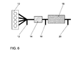
- an internal combustion engine 10 has an exhaust gas aftertreatment arrangement in an exhaust gas line, which has the following in the flow direction, a first lambda probe 12, which is designed to emit a continuous lambda signal, a pre-catalyst 14, a second lambda probe 16, which is used to emit a jump signal is formed, a NO x storing catalyst 18 and a NOx sensor 20.
- the exhaust-gas aftertreatment arrangement following on, a first exhaust bank 100 and a second exhaust bank 200, the lead 22 together and in a common NO x storage 18 open, which is a NO x sensor 20 downstream.
- the first exhaust bank 100 includes, seen in the flow direction, a first lambda probe 112 of the first exhaust bank 100, which is designed to emit a steady lambda signal, a precatalyst 114 of the first exhaust bank 100 and a second lambda probe 116 of the first exhaust bank 100, which is designed to emit a jump signal
- the second exhaust bank 200 includes, seen in the flow direction, a first lambda probe 212 of the second exhaust bank 200, which is designed to emit a steady lambda signal, a pre-catalyst 214 of the second exhaust bank 200 and a second lambda probe 216 of the second exhaust bank 200, which is designed to emit a jump signal ,
- Fig. 1 and 2 illustrate based on graphs for lambda values over time, a measurement of an oxygen storage capacity (OSC - O xygen- S torage- C apacity) taking advantage of a NO x regeneration of an internal combustion engine having a configuration according to Fig 6.
- horizontal axis 24 is time t
- vertical axis 26 is a lambda value
- vertical axis 28 is a probe voltage.
- a graph 30 shows a time course of lambda before the pre-catalyst 14.
- a graph 32 shows a probe voltage of the lambda probe 16 after the pre-catalyst 14.
- a graph 34 shows a probe voltage of the NO x sensor 20 after the NO x storage catalyst 18.
- a NO x regeneration is requested, wherein previously the internal combustion engine was operated in a lean operation with lambda >> 1.
- a lambda in the rich range (rich exhaust gas composition) of, for example, 0.8 to 0.9 is set for the NO x regeneration before the precatalyst 14.
- This phase is ended by changing the lambda to the NO x storage catalytic converter 18 from lean to rich, ie the probe voltage 34 increases abruptly.
- the OSC measurement thus takes place in the time interval t 1 -t 3 and the NO x regeneration in the time interval t 1 -t 2 .
- these two processes overlap in time or partially in parallel and take less time overall, as if both processes would run sequentially or separately.
- the lambda signals 32 and 34 are made plausible namely with respect to their dynamic behavior checked and with regard to the exchange of respective first and second lambda probes in a Two-bank system, as shown in Fig. 7, monitors what follows more closely is described.
- a jump from rich exhaust gas composition to lean exhaust gas composition takes place. This is used to test a dynamic behavior of the lambda probe 12 before the pre-catalyst 14.
- the dynamic measurement of the first lambda probe 12 is labeled 52.
- the gradient is used as delta O 2 / dt, delta voltage / dt or delta oxygen pump current / dt. For example, the gradient between the desired lambda values and the actually measured gradient of the lambda signal is compared. If the dynamic value falls below a predetermined threshold, errors are detected.
- the jump from rich exhaust gas composition to lean exhaust gas composition at time t 3 at the end of the OSC measurement 46 is utilized.
- the dynamic measurement of the second lambda probe 16 is labeled 54.
- the measurement and evaluation of the probe dynamics for example, analogous to the first lambda probe 12 before the pre-catalyst 14th
- the maximum gradient can also be used as the dynamic criterion which changes when you change from rich exhaust gas composition lean exhaust gas composition.
- an averaged gradient calculated from a minimum fat lambda value to a minimum lean lambda results.
- a rough plausibility check of the second lambda probe 16 after the precatalyst 14 in relation to the first lambda probe 12 before the precatalyst 14 takes place in the respective measuring phase "lean" in the time interval t 2 -t 3 or "fat” in the time interval t 1 -t 2 .
- After setting of rich mixture before the pre-catalyst 14 is checked after a corresponding Entprellzeit whether the lambda after the pre-catalyst 14 is also displayed in bold.
- a Release defined, resulting from the sub-approvals of the individual test functions such as catalyst testing, lambda testing, etc.
- a global Release defines the physical testing conditions of each partial test considered. Only when this release is given, the active measuring phase the lambda adjustment executed.
- Figs. 3, 4 and 5 illustrate a flow of monitoring for probe interchange between the first lambda probes 112, 212 upstream of the precatalysts 114, 214 and the second lambda probes 116, 216 after the pre-catalysts 114, 214 respectively of the two exhaust banks 100 and 200.
- Fig. 3 shows a temporal History of lambda values in an exhaust aftertreatment arrangement in State "i.O.”
- Fig. 4 shows a time course of lambda values at a Exhaust after-treatment arrangement in the state "exchanged second lambda probes 116, 216 after the pre-catalyst 114, 214 "and Fig.
- FIGS. 3, 4 and 5 shows a temporal History of lambda values in an exhaust aftertreatment device in the state "exchanged first lambda probes 112, 212 before the precatalyst 114, 214.
- the upper axbox in each case in FIGS. 3, 4 and 5 relates to the first exhaust gas bank 100 and the respective lower axbox relates to the second exhaust bank 200.
- Graph 130 shows a time course of Lambda according to the first lambda probe 112 before the pre-catalyst 114 for the first exhaust bank 100 and graph 132 shows a time profile of lambda according to the second lambda probe 116 after the pre-catalyst 114 for the first Exhaust bank 100.
- Graph 230 shows a time course of lambda according to the first lambda probe 212 before the pre-catalyst 214 for the second exhaust bank 200 and graph 232 shows a time course of lambda according to the second Lambda probe 216 after the pre-catalyst 214 for the second exhaust bank 200th
- the first lambda probes 112, 212 or the second lambda probes 116, 216 during installation or replacement be installed swapped.
- the lambda control parameters fit one Exhaust bank 100, 200 not to the measured lambda signal. This results Incorrect control interventions, misdiagnosis or emission deterioration May have consequences.
- An interchangeable detection is performed in parallel with the active lambda operation for the OSC measurement 46 (FIG. 2), as graphically illustrated in FIG.
- the active lambda adjustment for the catalyst diagnosis for the two exhaust banks 100 and 200 is requested offset in time.
- the time offset T1 is selected such that initially the lambda adjustment for the first exhaust bank 100 takes place and the lambda adjustment for the second exhaust bank 200 is only performed when the first bank 100 has already completed the probe jump test at t 2 or in the event of a fault there was sufficient time to expire the diagnosis in the first exhaust bank 100.
- This necessary time shift is, for example, fixed, in particular via a delta T, or the time shift is determined via models that take into account the OSC of the precatalyst 114, 214 as a function of gas flow rate, catalyst temperature. Either the lean-fat jump or the fat-lean jump of the probe signals 132, 232 or 130, 230 is evaluated.
- FIG. 4 illustrates how reversed second lambda probes 116, 216 affect and are detected downstream of pre-catalysts 114, 214.
- the second lambda probe 116 does not react after the pre-catalyst 114 for this exhaust bank 100, but the second lambda probe 216 jumps after the pre-catalyst 214 of the second exhaust bank 200, as indicated by arrow 58.
- FIG. 5 illustrates how reversed first lambda probes 112, 212 act and are detected before precatalyst 114, 214.
- the lambda desired value 30a before the pre-catalyst 114 of the first exhaust bank 100 and the lambda desired value 30b before the pre-catalyst 214 of the second exhaust bank 200 with the lambda actual value 130, 230 of the first lambda sensors 112, 212 before the pre-catalyst 114, 214 compared with actively requested adjustment.
- a lambda setpoint adjustment for the first exhaust gas bank 100 is output in the time interval t 1 -t 2 (for example, rich in fat: catalyst clearing out).
- the first lambda probe 112 (signal 130) before the primary catalytic converter 114 of the first exhaust gas bank 100 does not react to the adjustment, but the first lambda probe 212 before the primary catalytic converter 214 of the second exhaust gas bank 200 (signal 230).
- the fat adjustment is terminated via the lambda signal 132 (FIG. 3) after the precatalytic converter 114 of the first exhaust gas bank 100.
- the signal 230 of the first lambda probe 212 is displayed before Pre-catalyst 214 of the second exhaust bank 200 lean indicate, while the signal 130 of the first lambda probe 112 does not react before the pre-catalyst 114 of the first exhaust bank 100.
- the exact reverse behavior results at the time staggered lambda adjustments for the second exhaust bank 200 in the time intervals t 1 '-t 2 ' and t 2 '-t 3 '.
- test result for catalytic converter and lambda probes is set to "checked” for this case (cycle flag or Z_flag set). If the test result for the OSC value from step 66 is between the value for a very good catalyst and a defective catalyst (n.i.O.), so in at decision step 68, branch 74 "moderately aged> OSC> boundary cat” to step 76 "number x checks for Z_flag", where x is for example a Number is from 2 to 5, and it is thus a number of x corresponding number of Tests requested before the catalyst is considered tested.
- step 68 Is the test result for the OSC value from step 66 in the area of a defective catalyst (n.i.O.), then in decision step 68, branch 78 becomes "OSC ⁇ boundary cat" is selected to step 80 "number y tests for Z_flag", where y for example, a number from 6 to 10, and it will thus one of the number y corresponding Number of tests requested before the catalyst as tested applies to debounce the error.
Abstract
Description
Die Erfindung betrifft ein Verfahren zum Betreiben einer Brennkraftmaschine, insbesondere
eines Kraftfahrzeuges, mit einer in einem Abgastrakt der Brennkraftmaschine
angeordneten Abgasnachbehandlungsanordnung mit wenigstens einem
Katalysator und einer stromauf des Katalysators angeordneten ersten Lambdasonde
und einer stromab des Katalysators angeordneten zweiten Lambdasonde,
wobei zur Bestimmung einer Sauerstoffspeicherfähigkeit des Katalysators in einem
ersten Schritt (a) ein Lambdawert vor dem Katalysator aktiv auf einen Wert
kleiner 1 verstellt wird, bis ein in dem Katalysator gespeicherter Sauerstoff vollständig
ausgetragen ist, und anschließend in einem zweiten Schritt (b) der Lambdawert
vor dem Katalysator aktiv auf einen Wert größer 1 verstellt wird, bis der
Katalysator vollständig mit Sauerstoff beladen ist, wobei mittels einer Sauerstoffbilanzierung
die Sauerstoffspeicherfähigkeit des Katalysators bestimmt wird, wobei
die Abgasnachbehandlungsanordnung zusätzlich einen dem Katalysator nachgeordneten
NOx-Speicherkatalysator aufweist, wobei unter vorbestimmten Bedingungen
eine zeitlich begrenzte NOx-Regeneration des NOx-Speicherkatalysators
durchgeführt wird, gemäß dem Oberbegriff des Anspruchs 1.The invention relates to a method for operating an internal combustion engine, in particular a motor vehicle, having an arranged in an exhaust tract of the internal combustion engine exhaust aftertreatment arrangement with at least one catalyst and upstream of the catalyst arranged first lambda probe and a downstream of the catalyst arranged second lambda probe, wherein for determining an oxygen storage capacity of Catalyst in a first step (a) a lambda value before the catalyst is actively adjusted to a value less than 1, until an oxygen stored in the catalyst is completely discharged, and then in a second step (b) the lambda value before the catalyst active on a Value greater than 1 is adjusted until the catalyst is completely laden with oxygen, wherein the oxygen storage capacity of the catalyst is determined by means of an oxygen balance, wherein the exhaust aftertreatment arrangement additionally a The catalyst downstream of the NOx storage catalytic converter, wherein under predetermined conditions, a time-limited NO x regeneration of the NO x storage catalytic converter is carried out according to the preamble of
Zur Diagnose des Zustandes eines Katalysators einer Brennkraftmaschine sind Verfahren bekannt, die eine Sauerstoffspeicherfähigkeit (OSC - Oxygen-Storage-Capacity) des Katalysators mittels aktiver Lambdaverstellung messen. Diese Speicherfähigkeit korreliert mit der Kohlenwasserstoff(HC)-Konvertierung im Katalysator. Wenn der Katalysator gute Konvertierungseigenschaften besitzt, werden die Lambdaschwankungen vor dem Katalysator, welche durch den Lambdaregler aktiv erzeugt und von einer ersten Lambdasonde erfaßt werden, durch die Sauerstoffspeicherfähigkeit des Katalysators geglättet. Hat der Katalysator infolge Alterung, Vergiftung durch verbleiten Kraftstoff oder durch Verbrennungsaussetzer keine oder nur verminderte Konvertierungseigenschaften, so schlägt die stromauf des Katalysators vorhandene Regelschwingung auf die Lambdasonde stromab des Katalysators durch. Durch Vergleich der Signalamplituden der beiden Lambdasonden kann auf einen funktionsfähigen oder defekten Katalysator geschlossen werden, wie beispielsweise aus der DE 23 28 459 A1 bekannt.For the diagnosis of the state of a catalytic converter of an internal combustion engine, methods are known which measure an oxygen storage capacity (OSC - O xygen S torage C apacity) of the catalyst by means of active lambda adjustment. This storage capacity correlates with the hydrocarbon (HC) conversion in the catalyst. If the catalyst has good conversion properties, the lambda fluctuations upstream of the catalytic converter, which are actively generated by the lambda controller and detected by a first lambda probe, are smoothed by the oxygen storage capacity of the catalytic converter. If the catalyst has no or only reduced conversion properties as a result of aging, poisoning by leaded fuel or by combustion misfires, the control oscillation present upstream of the catalytic converter strikes the lambda probe downstream of the catalytic converter. By comparing the signal amplitudes of the two lambda probes can be concluded that a functional or defective catalyst, as known for example from DE 23 28 459 A1.
Zu Diagnosezwecken wird die OSC zusätzlich mit einem Anspring- und Konvertierungsverhalten des Katalysators korreliert. Zur Messung des OSC wird beispielsweise zunächst durch Einstellung eines fetten Lambdawertes von beispielsweise 0,95 bis 0,98 ein ggf. in dem Katalysator gespeicherte Sauerstoff ausgeräumt und anschließend durch Einstellung eines Lambdawertes von beispielsweise 1,02 bis 1,05 mit einem mageren, sauerstoffreichen Abgas wieder mit Sauerstoff befüllt. Dabei wird die OSC über eine Sauerstoffbilanzierung gemessen. Das Entleeren und Befüllen des Katalysators mit Sauerstoff wird dabei über einen Sprung eines Ausgangssignals einer dem Katalysator nachgeschalteten Lambdasonde ins Fette bzw. ins Magere bestimmt und gesteuert.For diagnostic purposes, the OSC also has a light-off and conversion behavior of the catalyst correlates. For example, to measure the OSC first by setting a rich lambda value of, for example 0.95 to 0.98 an oxygen possibly stored in the catalyst and then by setting a lambda value of, for example, 1.02 to 1.05 with a lean, oxygen-rich exhaust gas refilled with oxygen. The OSC is measured by oxygen balancing. The emptying and filling the catalyst with oxygen is about a jump of a Output signal of the catalytic converter downstream lambda probe into the grease or destined and controlled.
Aus der DE 199 53 601 A1 ist ein Verfahren zum Überprüfen eines Abgaskatalysators einer Brennkraftmaschine bekannt, wobei während einer Diagnosezeit eine Sauerstoffbeladung des Abgaskatalysators erhöht und aus der während mehrerer Lambdaregelschwingungen gemessenen NOx-Konzentration auf die Konvertierungseigenschaften des Abgaskatalysators geschlossen wird.From DE 199 53 601 A1 a method for checking an exhaust gas catalytic converter of an internal combustion engine is known, wherein an oxygen charge of the exhaust gas catalyst increases during a diagnostic time and is concluded from the measured during several Lambdaregelschwingungen NO x concentration on the conversion properties of the catalytic converter.
Aus der DE 198 01 626 A1 ist eine Diagnose eines Katalysators im Abgas von Verbrennungsmotoren bekannt, wobei der Katalysator sowohl eine Sauerstoff- als auch eine Stickoxidspeicherfähigkeit aufweist und wobei die Sauerstoffkonzentration im Abgas vor dem Katalysator wiederholt so erhöht und verringert wird, daß sich die Änderung im Signal einer vor und hinter dem Katalysator angeordneten Abgassonde abbildet. Es wird eine erste Phasenverschiebung zwischen den Signalen beider Sonden beim Anstieg und eine zweite Phasenverschiebung beim Absenken der Sauerstoffkonzentration erfaßt und die Differenz der Phasenverschiebungen bestimmt. Wenn diese Differenz einen vorbestimmten Schwellwert nicht erreicht, wird ein Fehlersignal ausgegeben.From DE 198 01 626 A1 a diagnosis of a catalyst in the exhaust gas of Internal combustion engines, wherein the catalyst both an oxygen as also has a nitrogen oxide storage capacity and wherein the oxygen concentration in the exhaust gas before the catalyst is repeatedly increased and decreased so that the change in the signal one arranged in front of and behind the catalyst Flue gas probe images. There will be a first phase shift between the signals both probes at the rise and a second phase shift at Lowering the oxygen concentration detected and the difference of the phase shifts certainly. If this difference is a predetermined threshold not reached, an error signal is output.
Aus der DE 100 17 931 A1 ist es zur Diagnose einer Abgasreinigungsanlage einer
lambdageregelten Brennkraftmaschine bekannt, den Katalysator mit einer gewissen
Sauerstoffbelastung zu beaufschlagen, die größer ist, als die normale Betriebsbelastung.
Dies wird dadurch erreicht, daß die von der Schwingung des
Sondensignals der Vorkat-Lambdasonde eingeschlossene Fläche eines Sollwertes
vergrößert wird. Durch Auswertung der Schwingung des Signals der Nachkat-Lambdasonde
kann die Abgasreinigungsanlage überprüft werden. Ergibt diese
Diagnose eine Fehlfunktion der Abgasreinigungsanlage ohne daß die Fläche der
Schwingung des Sondensignals der Vorkat-Lambdasonde auf oder über einen
Sollwert vergrößert werden müßte, ist die Vorkat-Lambdasonde defekt. Ansonsten
kann auf ein Katalysatorversagen geschlossen werden.From
Aus der DE 198 03 828 A1 und der DE 41 12 478 ist ein Verfahren zum Bestimmen einer Sauerstoffspeicherfähigkeit eines Katalysators bekannt, wobei ein Sauerstoffgehalt des Abgases vor und nach dem Katalysator bestimmt, mit dem Luft- bzw. Abgasmassenstrom durch den Motor bzw. Katalysator multipliziert und das Produkt integriert wird. Die Integralwerte sind ein Maß für die Sauerstoffmengen, die dem Katalysator zufließen und aus dem Katalysator herausfließen. Die Differenz der Integralwerte liefert die Änderung des Sauerstoffüllungsgrades des Katalysators im Integrationszeitraum. Dabei wird bei dem Verfahren sichergestellt, daß bei der Diagnose eine vollständige Füllung des Katalysators mit Sauerstoff und eine anschließend völlige Leerung oder umgekehrt erfolgt.From DE 198 03 828 A1 and DE 41 12 478 a method for determining an oxygen storage capacity of a catalyst, wherein an oxygen content of the exhaust gas before and after the catalytic converter, with the air or exhaust gas mass flow multiplied by the engine or catalyst and the Product is integrated. The integral values are a measure of the amounts of oxygen, which flow to the catalyst and flow out of the catalyst. The difference the integral value provides the change in the oxygen level of the catalyst in the integration period. In the process, it is ensured that in the diagnosis, a complete filling of the catalyst with oxygen and followed by a complete emptying or vice versa.
Aus der DE 100 26 213 A1 ist ein Verfahren zum Konfigurieren einer Mehrzahl von Lambdasonden eines Verbrennungsmotors mit zwei Abgasbänken bekannt. Für eine gegebene Verbindungskonfiguration von Lambdasonden und Eingängen eines Motorsteuergerätes wird detektiert, mit welchen Eingängen die Lambdasonden jeweils verbunden sind. Auf dieser Grundlage wird eine korrekte Zuordnung der Lambdasonden zu den Abgasbänken vorgenommen.From DE 100 26 213 A1 a method for configuring a plurality Lambda sensors of an internal combustion engine with two exhaust banks known. For a given connection configuration of lambda probes and inputs an engine control unit is detected with which inputs the lambda probes each connected. On this basis, a correct assignment the lambda probes made to the exhaust banks.
Aus der EP 0 897 054 A1 ist ein Verfahren zur Vertauschungsprüfung von Lambdasonden bekannt. Bei einer mehrzylindrigen Brennkraftmaschine mit mindestens zwei separaten Abgasleitungen mit jeweils einem Katalysator und mindestens je einer Lambdasonde pro Abgasleitung wird während einer Prüfzeit, die mindestens der Reaktionszeit bzw. Umschaltzeit der Lambdasonde entspricht, Luft mittels einer Luftquelle einzeln zumindest einer Abgasleitung über zumindest einen Luftanschluß vor der Lambdasonde zugeführt. Ein dadurch veränderter Abgaswert wird von der dem Abgasstrang zugeordneten Lambdasonde schnell und eindeutig identifiziert. Falls das erwartete Signal nicht von der dem ABgasstrang zugeordneten Lambdasonde ausgeht, kann eine Vertauschung der Lambdasonden erkannt werden.EP 0 897 054 A1 discloses a method for permutation testing of lambda probes known. In a multi-cylinder internal combustion engine with at least two separate exhaust pipes, each with a catalyst and at least each A lambda probe per exhaust pipe is used during a test period that is at least corresponds to the reaction time or switching time of the lambda probe, air by means of a Air source individually at least one exhaust pipe via at least one air connection fed in front of the lambda probe. A thereby changed exhaust gas value is quickly and clearly from the lambda probe assigned to the exhaust system identified. If the expected signal is not from the exhaust line assigned Lambda probe emanates, a permutation of the lambda probes detected become.
Aus der DE 101 17 244 A1 ist ein Verfahren zur Erkennung vertauscht angeschlossener Sauerstoffsensoren, die im Abgasstrang einer Brennkraftmaschine hintereinander angeordnet und an eine Regeleinrichtung für die Kraftstoffeinspritzung angeschlossen sind, bekannt. Während eines Prüfzeitraumes wird die Kraftstoffeinspritzung abgeschaltet oder das Kraftstoff-Luft-Verhältnis verändert und die Reaktionszeiten bis zum Auftreten der dadurch bedingten Signaländerung der O2-Sensoren gemessen und ausgewertet.From DE 101 17 244 A1 discloses a method for detecting reversed connected oxygen sensors, which are arranged in the exhaust line of an internal combustion engine one behind the other and connected to a control device for the fuel injection known. During a test period, the fuel injection is switched off or the air-fuel ratio changed and measured the reaction times until the occurrence of the resulting signal change in the O 2 sensors and evaluated.
Aus der DE 100 15 330 A1 ist es bekannt, bei einem Verbrennungsmotor mit
NOx- Speicherkatalysator im Abgasstrang in Abhängigkeit von Zustandsparametern
des NOx-Speicherkatalysators NOx-Regenerationsmaßnahmen durchzuführen.
Bei im Abgasstrang parallel angeordneten NOx-Speicherkatalysatoren wird
eine gerade durchgeführte NOx-Regenerationsmaßnahme in Abhängigkeit von
dem spätesten Zeitpunkt beendet, an dem ein für die Beendigung einer
NOx-Regenerationsmaßnahme charakteristischer Zustandsparameter-Wert an
einem der NOx-Speicherkatalysatoren gemessen wird. It is known from
Der Erfindung liegt die Aufgabe zugrunde, ein Verfahren der o.g. Art bzgl. Diagnosezeiten und Diagnosehäufigkeit für die Abgasnachbehandlungsanordnung zu verbessern.The invention is based on the object, a method of o.g. Type regarding diagnosis times and diagnostic frequency for the exhaust aftertreatment device improve.
Diese Aufgabe wird erfindungsgemäß durch ein Verfahren der o.g. Art mit den in
Anspruch 1 gelöst. Vorteilhafte Ausgestaltungen der Erfindung sind in den abhängigen
Ansprüchen angegeben.This object is achieved by a method of o.g. Kind with the in
Dazu ist es erfindungsgemäß vorgesehen, daß die NOx-Regeneration als erster Schritt (a) bestimmt und nach Beendigung der NOx-Regeneration der zweite Schritt (b) durchgeführt wird.For this purpose, it is provided according to the invention that the NO x regeneration is determined as the first step (a) and after completion of the NO x regeneration the second step (b) is carried out.
Dies hat den Vorteil, daß die Bestimmung der Sauerstoffspeicherfähigkeit des Katalysators mit einer NOx-Regeneration des NOx-Speicherkatalysators derart kombiniert ist, daß die Regenerationsphase der NOx-Regeneration gleichzeitig als Sauerstoffausräumphase zur Bestimmung der Sauerstoffspeicherfähigkeit des Katalysators dient. Dies reduziert und minimiert Diagnosezeiten mit Abweichung vom optimalen Betriebsmodus der Brennkraftmaschine für einen momentanen Betriebszustand derselben.This has the advantage that the determination of the oxygen storage capacity of the catalyst is combined with a NO x regeneration of the NO x storage catalyst such that the regeneration phase of the NO x regeneration simultaneously serves as an oxygen evacuation phase for determining the oxygen storage capacity of the catalyst. This reduces and minimizes diagnostic times with deviation from the optimum operating mode of the internal combustion engine for a current operating state thereof.
Beispielsweise ist der Katalysator ein Vorkatalysator oder ein Hauptkatalysator.For example, the catalyst is a precatalyst or a main catalyst.
Zweckmäßigerweise laufen Diagnosen von Katalysatorzustand und Zustand der Lambdasonden parallel ab, so daß Diagnosezeiten verringert und Homogenphasen für Diagnosen verkürzt sind.Conveniently, diagnoses of catalyst state and condition of run Lambda sensors in parallel, so that reduced diagnostic times and homogeneous phases are shortened for diagnoses.
Die Bestimmung wenigstens eines Parameters der Lambdasonden umfaßt beispielsweise
eine Plausibilitätsprüfung, wobei im ersten Schritt (a) und/oder im
zweiten Schritt (b) geprüft wird, ob erste und zweite Lambdasonde gleichzeitig die
erwartete fette bzw. magere Abgaszusammensetzung anzeigen. In dem Fall, daß
die Plausibilitätsprüfung eine Plausibilitätsverletzung ergibt, d.h. eine unterschiedliche
Anzeige der Abgaszusammensetzung vor und nach dem Katalysator durch
der beiden Lambdasonden, wird bestimmt, ob die erste oder zweite Lambdasonde
defekt ist. Zur Bestimmung der fehlerhaften Lambdasonde wird zweckmäßigerweise
eine vorbestimmte Betriebsart der Brennkraftmaschine, insbesondere ein
Homogen-Lambda-1-Betrieb, eingestellt.The determination of at least one parameter of the lambda probes comprises, for example
a plausibility check, wherein in the first step (a) and / or in the
second step (b) is checked whether the first and second lambda probe simultaneously
indicate expected rich or lean exhaust gas composition. In the case that
the plausibility check results in a plausibility violation, i. a different one
Display of the exhaust gas composition before and after the catalyst by
of the two lambda probes, it is determined whether the first or second lambda probe
is defective. For determining the faulty lambda probe is expediently
a predetermined mode of operation of the internal combustion engine, in particular a
Für eine Abgasnachbehandlungsanordnung mit zwei parallel im Abgasstrang angeordneten Katalysatoren umfaßt die Bestimmung wenigstens eines Parameters der Lambdasonden beispielsweise eine Vertauschung der jeweiligen ersten Lambdasonden vor den Katalysatoren und/oder der jeweiligen zweiten Lambdasonden nach den Katalysatoren, wobei der Schritt (a) für einen zweiten der parallelen Katalysatoren um eine vorbestimmte Zeit versetzt später ausgeführt wird, als für den entsprechend anderen ersten der beiden parallelen Katalysatoren, wobei eine Vertauschung des Anschlusses der beiden ersten Lambdasonden der beiden Katalysatoren bestimmt wird, wenn für eine vorbestimmte Anzahl von Zyklen der Schritte (a) und (b) die erste Lambdasonde des zweiten Katalysators eine Zustandsänderung des Abgases vor der ersten Lambdasonde des ersten Katalysators anzeigt, und wobei eine Vertauschung des Anschlusses der beiden zweiten Lambdasonden der beiden Katalysatoren bestimmt wird, wenn für eine vorbestimmte Anzahl von Zyklen der Schritte (a) und (b) die zweite Lambdasonde des zweiten Katalysators eine Zustandsänderung des Abgases vor der zweiten Lambdasonde des ersten Katalysators anzeigt. Die Zustandsänderung des Abgases ist beispielsweise ein Sprung von magerer Abgaszusammensetzung zu fetter Abgaszusammensetzung oder ein Sprung von fetter Abgaszusammensetzung zu magerer Abgaszusammensetzung ist.For an exhaust aftertreatment arrangement with two arranged in parallel in the exhaust system Catalysts comprise the determination of at least one parameter the lambda probes, for example, a permutation of the respective first Lambda sensors in front of the catalysts and / or the respective second lambda probes according to the catalysts, wherein step (a) is for a second of the parallel Catalysts offset by a predetermined time later executed as for the corresponding other first of the two parallel catalysts, wherein an exchange of the connection of the two first lambda probes of the two Catalysts is determined when for a predetermined number of cycles of Steps (a) and (b) the first lambda probe of the second catalyst, a state change the exhaust gas before the first lambda probe of the first catalyst indicating an interchanging of the terminal of the two second Lambda sensors of the two catalysts is determined when for a predetermined Number of cycles of steps (a) and (b) the second lambda probe of the second catalyst, a state change of the exhaust gas before the second lambda probe of the first catalyst. The state change of the exhaust gas is for example, a jump from lean exhaust gas composition to rich exhaust gas composition or a leap from rich exhaust gas composition to leaner Exhaust gas composition is.
In einer bevorzugten Weiterbildung der Erfindung umfaßt die Bestimmung wenigstens eines Parameters der Lambdasonden ein Dynamikverhalten der Lambdasonden, wobei ein Gradient der zeitliche Änderung eines Ausgangssignals der Lambdasonden bestimmt wird und eine fehlerhafte Lambdasonde bestimmt wird, wenn der Gradient kleiner als ein vorbestimmter Wert ist. Der Gradient der zeitliche Änderung beim Übergang von fetter Abgaszusammensetzung zu magerer Abgaszusammensetzung wird beispielsweise am Ende von Schritt (b) bestimmt. Zweckmäßigerweise wird ein maximaler Gradient oder ein gemittelter Gradient bestimmt und mit einem entsprechenden, vorbestimmten Wert verglichen. In a preferred embodiment of the invention, the determination comprises at least a parameter of the lambda probes a dynamic behavior of the lambda probes, wherein a gradient of the temporal change of an output signal of the lambda probes is determined and a faulty lambda probe is determined, if the gradient is less than a predetermined value. The gradient of the temporal change at the transition from rich exhaust gas composition to lean exhaust gas composition is determined, for example, at the end of step (b). Conveniently, a maximum gradient or an averaged gradient is determined and compared with a corresponding predetermined value.
Um den aktiven Eingriff von Diagnosen, welche sich ggf. sowohl auf Verbrauch als auch auf Schadstoffemission negativ auswirken können, so gering wie möglich zu halten, werden weitere Prüfzyklen in Abhängigkeit vom Ergebnis der Bestimmung der Sauerstoffspeicherfähigkeit angefordert.To the active intervention of diagnoses, which may affect both consumption and also have a negative impact on pollutant emissions, as low as possible hold, further test cycles will be dependent on the result of the determination the oxygen storage capability requested.
Beispielsweise für den Fall, daß die Sauerstoffspeicherfähigkeit einen Wert im Bereich eines frischen Katalysators ergibt und die Lambdasonden als funktionsfähig erkannt worden sind, werden für ein vorbestimmtes Zeitintervall, insbesondere bis zum nächsten Neustart der Brennkraftmaschine, keine weiteren Prüfzyklen angefordert.For example, in the case where the oxygen storage ability has a value in the range gives a fresh catalyst and the lambda probes as functional be recognized for a predetermined time interval, in particular until for the next restart of the internal combustion engine, no further test cycles requested.
Beispielsweise für den Fall, daß die Sauerstoffspeicherfähigkeit einen Wert im Bereich zwischen einem frischen Katalysator und einem defekten Katalysator ergibt, wird eine vorbestimmte erste Anzahl, insbesondere 2 bis 5, von weiteren Prüfzyklen angefordert.For example, in the case where the oxygen storage ability has a value in the range between a fresh catalyst and a defective catalyst, becomes a predetermined first number, in particular 2 to 5, of further test cycles requested.
Beispielsweise für den Fall, daß die Sauerstoffspeicherfähigkeit einen Wert im Bereich eines defekten Katalysators ergibt, wird eine vorbestimmte zweite Anzahl, insbesondere 6 bis 10, von weiteren Prüfzyklen angefordert.For example, in the case where the oxygen storage ability has a value in the range of a defective catalyst, a predetermined second number, in particular 6 to 10, requested by further test cycles.
Zweckmäßigerweise ist die erste Anzahl von weiteren Prüfzyklen kleiner als die zweite Anzahl von weiteren Prüfzyklen.Conveniently, the first number of further test cycles is smaller than that second number of further test cycles.
Zweckmäßigerweise wird im ersten Schritt (a) ein Lambdawert im Bereich von 0,95 bis 0,98 oder kleiner und im zweiten Schritt (b) ein Lambdawert im Bereich von 1,02 bis 1,05, insbesondere 1,03, eingestellt.Conveniently, in the first step (a), a lambda value in the range of 0.95 to 0.98 or less and in the second step (b) a lambda value in the range from 1.02 to 1.05, especially 1.03.
In einer bevorzugten Weiterbildung der Erfindung umfaßt die Bestimmung wenigstens eines Parameters der Lambdasonden eine Prüfung einer Magerspannung und/oder einer Fettspannung der ersten und/oder zweiten Lambdasonde.In a preferred embodiment of the invention, the determination comprises at least a parameter of the lambda probes a test of a lean stress and / or a fatigue voltage of the first and / or second lambda probe.
Weitere Merkmale, Vorteile und vorteilhafte Ausgestaltungen der Erfindung ergeben sich aus den abhängigen Ansprüchen, sowie aus der nachstehenden Beschreibung der Erfindung anhand der beigefügten Zeichnungen. Diese zeigen in
- Fig. 1
- eine graphische Veranschaulichung einer Sauerstoffspeicherkapazität(OSC)-Messung eines Vorkatalysators bei Übergang von einer NOx-Regeneration in einen Magerbetrieb;
- Fig. 2
- eine graphische Veranschaulichung einer Kombination von Katalysatorund Lambdasonden-Diagnose;
- Fig. 3
- eine graphische Veranschaulichung einer Lambdasonden-Vertauschungserkennung für ein Zwei-Bank-Konzept bei korrekt angeschlossenen Lambdasonden;
- Fig. 4
- eine graphische Veranschaulichung einer Lambdasonden-Vertauschungserkennung für ein Zwei-Bank-Konzept bei vertauschten Lambdasonden nach den Katalysatoren der Abgasbänke;
- Fig. 5
- eine graphische Veranschaulichung einer Lambdasonden-Vertauschungserkennung für ein Zwei-Bank-Konzept bei vertauschten Lambdasonden vor den Katalysatoren der Abgasbänke;
- Fig. 6
- eine schematische Darstellung einer Brennkraftmaschine mit Vorkatalysator und NOx-Speicherkatalysator;
- Fig. 7
- eine schematische Darstellung einer Brennkraftmaschine mit zwei Abgasbänken, die jeweils einen Vorkatalysator mit jeweils stromauf und stromab angeordneten Lambdasonden aufweisen und
- Fig. 8
- ein schematisches Blockdiagramm eines Verfahrens mit reduzierter Diagnosezeit für eine aktive Katalysatordiagnose.
- Fig. 1
- a graphical illustration of an oxygen storage capacity (OSC) measurement of a precatalyst in transition from a NOx regeneration to a lean operation;
- Fig. 2
- a graphical illustration of a combination of catalyst and lambda probe diagnostics;
- Fig. 3
- a graphical illustration of a lambda probe Vertauschungserkennung for a two-bank concept with correctly connected lambda probes;
- Fig. 4
- a graphical illustration of a Lambda probe interchangeability detection for a two-bank concept with reversed lambda probes after the catalysts of the exhaust banks;
- Fig. 5
- a graphical illustration of a lambda probe Verschauschungserkennung for a two-bank concept with reversed lambda probes before the catalysts of the exhaust banks;
- Fig. 6
- a schematic representation of an internal combustion engine with pre-catalyst and NOx storage catalyst;
- Fig. 7
- a schematic representation of an internal combustion engine with two exhaust banks, each having a precatalyst with each upstream and downstream arranged lambda probes and
- Fig. 8
- a schematic block diagram of a method with reduced diagnosis time for an active catalyst diagnosis.
Die Erfindung wird nachfolgend beispielhaft für zwei Abgasnachbehandlungsanordnungen
wie in den Fig. 6 und 7 dargestellt, beschrieben. In Fig. 6 weist eine
Brennkraftmaschine 10 in einem Abgasstrang eine Abgasnachbehandlungsanordnung
auf, die in Strömungsrichtung gesehen folgendes aufweist, eine erste Lambdasonde
12, welche zur Abgabe eines stetigen Lambdasignals ausgebildet ist,
einen Vorkatalysator 14, eine zweite Lambdasonde 16, welche zur Abgabe eines
Sprungsignals ausgebildet ist, einen NOx-Speicherkatalysator 18 und einen
NOx-Sensor 20. Bei der Ausführung der Brennkraftmaschine 10 gemäß Fig. 7
weist die Abgasnachbehandlungsanordnung folgendes auf, eine erste Abgasbank
100 und eine zweite Abgasbank 200, die bei 22 zusammen führen und in einen
gemeinsamen NOx-Speicherkatalysator 18 münden, dem ein NOx-Sensor 20
nachgeordnet ist. Die erste Abgasbank 100 umfaßt in Strömungsrichtung gesehen
eine erste Lambdasonde 112 der ersten Abgasbank 100, welche zur Abgabe eines
stetigen Lambdasignals ausgebildet ist, einen Vorkatalysator 114 der ersten
Abgasbank 100 sowie eine zweite Lambdasonde 116 der ersten Abgasbank 100,
welche zur Abgabe eines Sprungsignals ausgebildet ist. Die zweite Abgasbank
200 umfaßt in Strömungsrichtung gesehen eine erste Lambdasonde 212 der zweiten
Abgasbank 200, welche zur Abgabe eines stetigen Lambdasignals ausgebildet
ist, einen Vorkatalysator 214 der zweiten Abgasbank 200 sowie eine zweite
Lambdasonde 216 der zweiten Abgasbank 200, welche zur Abgabe eines
Sprungsignals ausgebildet ist.The invention will be described below by way of example for two exhaust aftertreatment arrangements as shown in FIGS. 6 and 7. 6, an
Fig. 1 und 2 veranschaulichen anhand von Graphen für Lambdawerte über die
Zeit eine Messung einer Sauerstoffspeicherkapazität (OSC - Oxygen-Storage-Capacity)
unter Ausnutzung einer NOx-Regeneration bei einer
Brennkraftmaschine mit einer Konfiguration gemäß Fig. 6. In Fig. 1 ist auf den horizontalen
Achsen 24 die Zeit t, auf der vertikalen Achse 26 ein Lambdawert und
auf der vertikalen Achse 28 eine Sondenspannung aufgetragen. Ein Graph 30
zeigt einen zeitlichen Verlauf von Lambda vor dem Vorkatalysator 14. Ein Graph
32 zeigt eine Sondenspannung der Lambdasonde 16 nach dem Vorkatalysator 14.
Ein Graph 34 zeigt eine Sondenspannung des NOx-Sensors 20 nach dem
NOx-Speicherkatalysator 18. Zusätzlich sind die Signale "Anforderung der
NOx-Regeneration" 36, "OSC-Messung" 38, "Ende der Messung OSC" 40 und
"Freigabe Magerbetrieb" 42 in ihrer zeitlichen Korrelation zu den Graphen 30, 32
und 34 aufgetragen. Zum Zeitpunkt t1 wird eine NOx-Regeneration angefordert,
wobei vorher die Brennkraftmaschine in einem Magerbetrieb mit Lambda>>1 betrieben
wurde. Im Zeitintervall t1-t2 wird zur NOx-Regeneration vor dem Vorkatalysator
14 ein Lambda im fetten Bereich (fette Abgaszusammensetzung) von beispielsweise
0,8 bis 0,9 eingestellt. Beendet wird diese Phase durch Wechsel des
Lambdas nach dem NOx-Speicherkatalysator 18 von mager nach fett, d.h. die
Sondenspannung 34 steigt sprungartig an. Bereits vor dem Zeitpunkt t2 ist der gesamte
Sauerstoff aus dem Vorkatalysator 14 ausgeräumt, was an dem Anstieg der
Sondenspannung 32 der Lambdasonde 16 nach dem Vorkatalysator 14 (Sprung
ins Fette) ersichtlich ist. Sobald das gesamte in dem NOx-Speicherkatalysator 18
enthaltene NOx umgesetzt ist, steigt auch die Sondenspannung 34, da das Regenerationsabgas
bis nach dem NOx-Speicherkatalysator 18 durchbricht, was zu
einem Ende der NOx-Regeneration zum Zeitpunkt t2 führt. Je nach Betriebsartanforderung
könnte nun in den Lambda-1-Betrieb oder den Magerbetrieb übergegangen
werden. Es wird jedoch unabhängig von der sich der NOx-Regeneration
im Zeitintervall t1-t2 anschließenden Betriebsart nach Beendigung der
NOx-Regeneration bei t2 auf einen mageren Lambda-1-Punkt (Lambda 1,02 bis
1,05) umgeschaltet und der in den Vorkatalysator eingetragene Sauerstoff aufkumuliert,
bis die Sondenspannung 32 der Lambdasonde 16 nach dem Vorkatalysator
14 den Durchbruch von magerem Abgas zum Zeitpunkt t3 anzeigt. Im Zeitintervall
44 vom Zeitpunkt t2 bis zum Zeitpunkt t3 wird Sauerstoff in den Vorkatalysator
14 eingetragen, bis dieser vollständig mit Sauerstoff beladen ist. Somit wird
die NOx-Regeneration im Zeitintervall t1-t2 als OSC-Ausräumphase genutzt, so
daß diese nicht zusätzlich extra ablaufen muß. Wie mit Pfeil 46 in Fig. 2 angedeutet,
erfolgt somit die OSC-Messung im Zeitintervall t1-t3 und die NOx-Regeneration
im Zeitintervall t1-t2. Somit überlappen sich diese beiden Vorgänge zeitlich bzw.
teilweise parallel und benötigen insgesamt weniger Zeit, als wenn beide Vorgänge
seriell bzw. separat nacheinander ablaufen würden.Fig. 1 and 2 illustrate based on graphs for lambda values over time, a measurement of an oxygen storage capacity (OSC - O xygen- S torage- C apacity) taking advantage of a NO x regeneration of an internal combustion engine having a configuration according to Fig 6. In Fig. 1,
Parallel zur OSC-Messung 46 werden die Lambdasignale 32 und 34 plausibilisiert
und zwar bzgl. ihres Dynamikverhaltens überprüft und hinsichtlich der Vertauschung
von jeweiligen ersten und zweiten Lambdasonden bei einem
Zwei-Bank-System, wie in Fig. 7 dargestellt, überwacht, was nachfolgend genauer
beschrieben wird.Parallel to the
Wie in Fig. 2 mit Pfeil 48 angedeutet, erfolgt im Zeitbereich vor t1 eine Prüfung der
Magerspannung der Sondensignale 32 und 34. Wie weiterhin mit Pfeil 50 angedeutet,
erfolgt im Zeitintervall zwischen t1 und t2, also während der Ausräumphase
der OSC-Messung bzw. der NOx-Regeneration, eine Prüfung der Fettspannung
der Sondensignale 32 und 34.As indicated in FIG. 2 by
Am Ende der NOx-Regeneration bzw. des Ausräumschrittes der OSC-Messung
zum Zeitpunkt t2 erfolgt ein Sprung von fetter Abgaszusammensetzung zu magerer
Abgaszusammensetzung. Dies wird genutzt, um ein Dynamikverhalten der
Lambdasonde 12 vor dem Vorkatalysator 14 zu prüfen. In Fig. 2 ist die Dynamikmessung
der ersten Lambdasonde 12 mit 52 gekennzeichnet. Als Bewertungskriterium
für die Dynamik wird beispielsweise der Gradient als Delta O2/dt, Delta-Spannung/dt
oder Delta-Sauerstoffpumpstrom/dt herangezogen. Es wird beispielsweise
der Gradient zwischen den Lambdasollwerten mit dem tatsächlich
gemessenen Gradienten des Lambdasignals verglichen. Unterschreitet der Dynamikwert
eine vorbestimmte Schwelle, wird auf Fehler erkannt.At the end of the NO x regeneration or the clearing step of the OSC measurement at time t 2 , a jump from rich exhaust gas composition to lean exhaust gas composition takes place. This is used to test a dynamic behavior of the
Zur Bewertung der Dynamik der Sondenspannung 32 der zweiten Lambdasonde
32 nach dem Vorkatalysator 14 wird der Sprung von fetter Abgaszusammensetzung
zu magerer Abgaszusammensetzung zum Zeitpunkt t3 am Ende der
OSC-Messung 46 genutzt. In Fig. 2 ist die Dynamikmessung der zweiten Lambdasonde
16 mit 54 gekennzeichnet. Die Messung und Bewertung der Sondendynamik
erfolgt beispielsweise analog wie bei der ersten Lambdasonde 12 vor dem
Vorkatalysator 14.To evaluate the dynamics of the
Als Dynamikkriterium kann beispielsweise auch der maximale Gradient herangezogen werden, der sich beim Wechsel von fetter Abgaszusammensetzung nach magerer Abgaszusammensetzung ergibt. Alternativ wird ein gemittelter Gradient berechnet, der sich von einem Mindestfett-Lambdawert zu einem Mindestmager-Lambda ergibt.For example, the maximum gradient can also be used as the dynamic criterion which changes when you change from rich exhaust gas composition lean exhaust gas composition. Alternatively, an averaged gradient calculated from a minimum fat lambda value to a minimum lean lambda results.
Eine grobe Plausibilisierung der zweiten Lambdasonde 16 nach dem Vorkatalysator
14 in Relation zu der ersten Lambdasonde 12 vor dem Vorkatalysator 14 erfolgt
in der jeweiligen Meßphase "Mager" im Zeitintervall t2-t3 bzw. "Fett" im Zeitintervall
t1-t2. Im Mageren mit Lambda > 1, beispielsweise Lambda = 1,03 bis 1,05,
wird nach entsprechender Entprellzeit, welche Gaslaufzeiten und Katalysator-Ausräumzeiten
berücksichtigt, geprüft, ob die zweite Lambdasonde 16 nach
dem Vorkatalysator 14 ebenfalls mager anzeigt. Nach Einstellung von fettem Gemisch
vor dem Vorkatalysator 14 wird nach entsprechender Entprellzeit überprüft,
ob das Lambda nach dem Vorkatalysator 14 ebenfalls fett anzeigt.A rough plausibility check of the
Ergeben sich bei dieser Grobplausibilisierung zwischen "Lambda vor dem Vorkatalysator
14" und "Lambda nach dem Vorkatalysator 14" Plausibilitätsverletzungen,
weil beispielsweise die erste Lambdasonde 12 vor dem Vorkatalysator "fett"
anzeigt, wohingegen die zweite Lambdasonde 16 nach dem Vorkatalysator "mager"
anzeigt oder umgekehrt, wird ein Fehlerverdacht gesetzt. Daraufhin wird eine
genaue Überprüfung angestoßen, die die Zuordnung des Plausibilitätsfehlers zum
Fehlerort gewährleisten soll, d.h. es wird festgestellt, ob die erste Lambdasonde
12 oder die zweite Lambdasonde 16 defekt ist. Für diese Überprüfung wird
zweckmäßigerweise eine Betriebsart angefordert, die günstig für eine schnelle
Fehlerfindung ist, wie beispielsweise ein Homogen-Lambda-1-Betrieb.Result in this rough plausibility between "lambda before the pre-catalyst
14 "and" lambda after the pre-catalyst 14 "plausibility violations,
because, for example, the
Um das gleichzeitige, parallel Ablaufen der Diagnose zu gewährleisten, wird eine Freigabe definiert, die sich aus den Unterfreigaben der einzelnen Prüffunktionen ergibt, wie Katalysatorprüfung, Lambdaprüfung usw.. Alternativ wird eine globale Freigabe definiert, die die physikalischen Prüfbedingungen der einzelnen Teilprüfungen berücksichtigt. Erst wenn diese Freigabe gegeben ist, wird die aktive Meßphase der Lambdaverstellung ausgeführt.To ensure the simultaneous, parallel running of the diagnosis, a Release defined, resulting from the sub-approvals of the individual test functions such as catalyst testing, lambda testing, etc. Alternatively, a global Release defines the physical testing conditions of each partial test considered. Only when this release is given, the active measuring phase the lambda adjustment executed.
Fig. 3, 4 und 5 veranschaulichen einen Ablauf der Überwachung auf Sondenvertauschung
zwischen den ersten Lambdasonden 112, 212 vor den Vorkatalysatoren
114, 214 und den zweiten Lambdasonden 116, 216 nach den Vorkatalysatoren
114, 214 jeweils der beiden Abgasbänke 100 und 200. Fig. 3 zeigt einen zeitlichen
Verlauf von Lambdawerten bei einer Abgasnachbehandlungsanordnung im
Zustand "i.O.", Fig. 4 zeigt einen zeitlichen Verlauf von Lambdawerten bei einer
Abgasnachbehandlungsanordnung im Zustand "vertauschte zweite Lambdasonden
116, 216 nach dem Vorkatalysator 114, 214" und Fig. 5 zeigt einen zeitlichen
Verlauf von Lambdawerten bei einer Abgasnachbehandlungsanordnung im Zustand
"vertauschte erste Lambdasonden 112, 212 vor dem Vorkatalysator 114,
214". Das in Fig. 3, 4 und 5 jeweils obere Achsenkreuz betrifft die erste Abgasbank
100 und das jeweilige untere Achsenkreuz betrifft die zweite Abgasbank 200. Figs. 3, 4 and 5 illustrate a flow of monitoring for probe interchange
between the first lambda probes 112, 212 upstream of the
Auf den horizontalen Achsen 10 ist wieder die Zeit t und auf den vertikalen Achsen
26 ein Lambdawert aufgetragen. Graph 130 zeigt einen zeitlichen Verlauf von
Lambda gemäß der ersten Lambdasonde 112 vor dem Vorkatalysator 114 für die
erste Abgasbank 100 und Graph 132 zeigt einen zeitlichen Verlauf von Lambda
gemäß der zweiten Lambdasonde 116 nach dem Vorkatalysator 114 für die erste
Abgasbank 100. Graph 230 zeigt einen zeitlichen Verlauf von Lambda gemäß der
ersten Lambdasonde 212 vor dem Vorkatalysator 214 für die zweite Abgasbank
200 und Graph 232 zeigt einen zeitlichen Verlauf von Lambda gemäß der zweiten
Lambdasonde 216 nach dem Vorkatalysator 214 für die zweite Abgasbank 200.
Bei einem System mit zwei Abgasbänken 100 und 200, wie in Fig. 7 dargestellt,
besteht als weitere Fehlerquelle die Möglichkeit, daß die ersten Lambdasonden
112, 212 oder die zweiten Lambdasonden 116, 216 beim Einbau oder Wechsel
vertauscht eingebaut werden. Dadurch passen die Lambda-Regelparameter einer
Abgasbank 100, 200 nicht zum gemessenen Lambdasignal. Daraus resultieren
falsche Reglereingriffe, die Fehldiagnosen oder Emissionsverschlechterungen zur
Folge haben können.On the
Eine Vertauschungserkennung wird parallel zu dem aktiven Lambdaeingriff für die
OSC-Messung 46 (Fig. 2) durchgeführt, wie in Fig. 3 graphisch veranschaulicht.
Hierzu wird die aktive Lambdaverstellung für die Katalysatordiagnose für die beiden
Abgasbänke 100 und 200 zeitlich versetzt angefordert. Der Zeitversatz T1
wird derart gewählt, daß zunächst die Lambdaverstellung für die erste Abgasbank
100 erfolgt und die Lambdaverstellung für die zweite Abgasbank 200 erst dann
durchgeführt wird, wenn für die erste Bank 100 die Prüfung über den Sondensprung
bei t2 bereits beendet wurde oder im Fehlerfall ausreichend Zeit zum Ablauf
der Diagnose in der ersten Abgasbank 100 gegeben war. Diese notwendige,
zeitliche Verschiebung ist beispielsweise fest bedatet, insbesondere über ein Delta-T,
oder die zeitliche Verschiebung wird über Modelle ermittelt, die das OSC des
Vorkatalysators 114, 214 in Abhängigkeit von Gasdurchsatz, Katalysatortemperatur
berücksichtigen. Ausgewertet wird entweder der Mager-Fett-Sprung oder der
Fett-Mager-Sprung der Sondensignale 132, 232 bzw. 130, 230.An interchangeable detection is performed in parallel with the active lambda operation for the OSC measurement 46 (FIG. 2), as graphically illustrated in FIG. For this purpose, the active lambda adjustment for the catalyst diagnosis for the two
Fig. 4 veranschaulicht, wie sich vertauschte zweite Lambdasonden 116, 216 nach
den Vorkatalysatoren 114, 214 auswirken und erkannt werden. Nach der Lambdaverstellung
bei t1 für die erste Abgasbank 100 reagiert die zweite Lambdasonde
116 nach dem Vorkatalysator 114 für diese Abgasbank 100 nicht, sondern es
springt die zweite Lambdasonde 216 nach dem Vorkatalysator 214 der zweiten
Abgasbank 200, wie mit Pfeil 58 angedeutet. Bei der anschließenden Verstellung
für die zweite Abgasbank 200 bei t1' gibt es die entsprechende, gleiche Fehlreaktion
der zweiten Lambdasonde 116 nach dem Vorkatalysator 114 der ersten Abgasbank
100, wohingegen die zweite Lambdasonde 216 nach dem Vorkatalysator
214 der zweiten Abgasbank 200 nicht reagiert, wie mit Pfeil 60 angedeutet. Wird
dieses Fehlverhalten in mehreren Meßphasen erkannt, so wird ein Fehler "zweite
Lambdasonden 116, 216 nach dem Vorkatalysator 114, 214 vertauscht" gesetzt.
Pfeil 56 bezeichnet eine maximale Zeit bis zu dem ein Sondensprung erwartet
wird.FIG. 4 illustrates how reversed second lambda probes 116, 216 affect and are detected downstream of
Fig. 5 veranschaulicht, wie sich vertauschte erste Lambdasonden 112, 212 vor
dem Vorkatalysator 114, 214 auswirken und erkannt werden. Zur Überwachung
wird hier der Lambda-Sollwert 30a vor dem Vorkatalysator 114 der ersten Abgasbank
100 und der Lambda-Sollwert 30b vor dem Vorkatalysator 214 der zweiten
Abgasbank 200 mit dem Lambda-Istwert 130, 230 der ersten Lambdasonden 112,
212 vor dem Vorkatalysator 114, 214 bei aktiv angeforderter Verstellung verglichen.
Zunächst wird im Zeitintervall t1-t2 eine Lambdasollverstellung für die erste
Abgasbank 100 ausgegeben (beispielsweise fett: Katalysator ausräumen). Im
Fehlerfall reagiert nicht die erste Lambdasonde 112 (Signal 130) vor dem Vorkatalysator
114 der ersten Abgasbank 100 auf die Verstellung, sondern die erste
Lambdasonde 212 vor dem Vorkatalysator 214 der zweiten Abgasbank 200 (Signal
230). Beendet wird die Fettverstellung über das Lambdasignal 132 (Fig. 3)
nach dem Vorkatalysator 114 der ersten Abgasbank 100. Bei der anschließenden
Verstellung nach Mager für die erste Abgasbank 100 im Zeitintervall t2-t3 wird das
Signal 230 der ersten Lambdasonde 212 vor dem Vorkatalysator 214 der zweiten
Abgasbank 200 mager anzeigen, während das Signal 130 der ersten Lambdasonde
112 vor dem Vorkatalysator 114 der ersten Abgasbank 100 nicht reagiert. Das
genau umgekehrte Verhalten ergibt sich bei den dazu zeitlich versetzten Lambdaverstellungen
für die zweite Abgasbank 200 in den Zeitintervallen t1'-t2' und t2'-t3'.
Nach einer entsprechend applizierbaren Anzahl von Verstellintervallen mit bestätigtem
Fehler, wird ein Fehler "erste Lambdasonden 112, 212 vor dem Vorkatalysator
114, 214 vertauscht" gesetzt. Ein Signal 62 für "Fehlerverdacht" und ein Signal
64 für "Fehler" ist in Fig. 5 dargestellt.FIG. 5 illustrates how reversed first lambda probes 112, 212 act and are detected before
Um den aktiven Eingriff von Diagnosen, der sowohl aus Verbrauchsgründen, als
auch aus Emissionsgründen negativ sein kann, so gering als möglich zu halten, ist
es vorgesehen, abhängig vom Diagnoseergebnis zu bewerten, wie viele Prüfzyklen
für ein sicheres Ergebnis notwendig sind. Dies ist auch in Fig. 8 anhand eines
schematischen Ablaufdiagramms veranschaulicht. Ergibt der Prüfzyklus in Schritt
66 "OSC-Messung durchgeführt (1. Ergebnis)" bzgl. der Katalysatordiagnose
(OSC-Messung) einen sehr großen OSC-Wert, der im Bereich eines Ergebnisses
für einen frischen Katalysator liegt, so wird in einem Entscheidungsschritt 68 die
Abzweigung 70 "OSC>>mäßg gealtert" zu Schritt 72 "Messende" gewählt und für
diesen Trip die aktive Diagnose unterbunden, insofern die Lambdasignale bei der
Prüfung plausibel und i.O. waren. Das Prüfergebnis für Katalysator und Lambdasonden
wird für diesen Fall auf "geprüft" gesetzt (Zyklus-Flag oder Z_flag gesetzt).
Liegt das Prüfergebnis für den OSC-Wert aus Schritt 66 zwischen dem Wert für
einen sehr guten Katalysator und einem defekten Katalysator (n.i.O.), so wird in
dem Entscheidungsschritt 68 die Abzweigung 74 "mäßig gealtert>OSC>Grenzkat"
zu Schritt 76 "Anzahl x Prüfungen für Z_flag" gewählt, wobei x beispielsweise eine
Zahl von 2 bis 5 ist, und es wird damit eine der Zahl x entsprechende Anzahl von
Prüfungen angefordert, bevor der Katalysator als geprüft gilt. Liegt das Prüfergebnis
für den OSC-Wert aus Schritt 66 im Bereich eines defekten Katalysators
(n.i.O.), dann wird in dem Entscheidungsschritt 68 die Abzweigung 78
"OSC<Grenzkat" zu Schritt 80 "Anzahl y Prüfungen für Z_flag" gewählt, wobei y
beispielsweise eine Zahl von 6 bis 10 ist, und es wird damit eine der Zahl y entsprechende
Anzahl von Prüfungen angefordert, bevor der Katalysator als geprüft
gilt, um den Fehler zu entprellen.To the active intervention of diagnoses, both for consumption, as
may also be negative for emission reasons, to keep it as low as possible
it is intended to evaluate how many test cycles, depending on the diagnostic result
necessary for a sure result. This is also in Fig. 8 based on a
schematic flow diagram illustrates. Returns the test cycle in
Claims (19)
dadurch gekennzeichnet, daß die NOx-Regeneration als erster Schritt (a) durchgeführt und nach Beendigung der NOx-Regeneration der zweite Schritt (b) durchgeführt wird.Method for operating an internal combustion engine, in particular a motor vehicle, having an exhaust gas aftertreatment arrangement arranged in an exhaust tract of the internal combustion engine with at least one catalytic converter and a first lambda probe arranged upstream of the catalytic converter and a second lambda probe arranged downstream of the catalytic converter, wherein for determining an oxygen storage capability of the catalytic converter in a first Step (a) a lambda value upstream of the catalyst is actively adjusted to a value less than 1 until an oxygen stored in the catalyst is completely discharged, and then in a second step (b) the lambda value before the catalyst actively adjusted to a value greater than 1 is until the catalyst is completely loaded with oxygen, wherein the oxygen storage capacity of the catalyst is determined by means of an oxygen balancing, wherein the exhaust aftertreatment arrangement additionally nachgeordn a catalyst eten NOx storage catalytic converter, wherein under predetermined conditions, a time-limited NO x regeneration of the NO x storage catalytic converter is performed,
characterized in that the NO x regeneration is performed as a first step (a) and after completion of the NO x regeneration, the second step (b) is performed.
Applications Claiming Priority (2)
| Application Number | Priority Date | Filing Date | Title |
|---|---|---|---|
| DE10331331A DE10331331B4 (en) | 2003-07-10 | 2003-07-10 | Method for operating an internal combustion engine |
| DE10331331 | 2003-07-10 |
Publications (2)
| Publication Number | Publication Date |
|---|---|
| EP1496225A2 true EP1496225A2 (en) | 2005-01-12 |
| EP1496225A3 EP1496225A3 (en) | 2007-05-30 |
Family
ID=33441714
Family Applications (1)
| Application Number | Title | Priority Date | Filing Date |
|---|---|---|---|
| EP04102669A Withdrawn EP1496225A3 (en) | 2003-07-10 | 2004-06-14 | Method for controlling an internal combustion engine |
Country Status (2)
| Country | Link |
|---|---|
| EP (1) | EP1496225A3 (en) |
| DE (1) | DE10331331B4 (en) |
Cited By (3)
| Publication number | Priority date | Publication date | Assignee | Title |
|---|---|---|---|---|
| WO2007128593A1 (en) * | 2006-05-05 | 2007-11-15 | Continental Automotive Gmbh | Method and device for the diagnosis of the effectiveness of a catalytic converter |
| WO2009089977A1 (en) * | 2008-01-14 | 2009-07-23 | Robert Bosch Gmbh | Method and controller for checking an exhaust gas aftertreatment system of an internal combustion engine |
| EP1857647A4 (en) * | 2005-01-31 | 2015-03-25 | Isuzu Motors Ltd | Method of raising temperature of exhaust-gas purifier and exhaust-gas purification system |
Families Citing this family (3)
| Publication number | Priority date | Publication date | Assignee | Title |
|---|---|---|---|---|
| DE102005034880B4 (en) * | 2005-07-26 | 2007-06-06 | Siemens Ag | Method and device for the diagnosis of an emission control system |
| DE102017216997A1 (en) | 2017-09-26 | 2019-03-28 | Bayerische Motoren Werke Aktiengesellschaft | Catalyst with OBD system |
| DE102017216998A1 (en) | 2017-09-26 | 2019-03-28 | Bayerische Motoren Werke Aktiengesellschaft | Catalyst with OBD system |
Citations (10)
| Publication number | Priority date | Publication date | Assignee | Title |
|---|---|---|---|---|
| DE2328459A1 (en) | 1973-01-31 | 1975-01-02 | Bosch Gmbh Robert | System for checking activity of catalytic reactors - signals bad functioning of such reactors and causes engine to run unstable |
| DE4112478A1 (en) | 1991-04-17 | 1992-10-22 | Bosch Gmbh Robert | METHOD AND DEVICE FOR ASSESSING THE AGE OF A CATALYST |
| EP0897054A1 (en) | 1997-08-11 | 1999-02-17 | Daimler-Benz Aktiengesellschaft | Method for permutation testing of lambda probes |
| DE19801626A1 (en) | 1998-01-17 | 1999-07-22 | Bosch Gmbh Robert | Catalyst diagnostics process for testing nitrogen oxide(s) storage capacity of i. c. engine exhaust gas catalyst |
| DE19803828A1 (en) | 1998-01-31 | 1999-08-05 | Bosch Gmbh Robert | Testing an exhaust gas catalytic converter in an internal combustion engine, for its ability to convert contaminants |
| DE19953601A1 (en) | 1999-11-08 | 2001-05-23 | Siemens Ag | Method for checking an exhaust gas catalytic converter of an internal combustion engine |
| DE10026213A1 (en) | 2000-05-26 | 2001-11-29 | Volkswagen Ag | Configuring combustion engine lambda probes by detecting to which controller inputs lambda probes are connected, controller providing correct association of probes and cylinder banks |
| DE10017931A1 (en) | 2000-04-11 | 2001-12-06 | Siemens Ag | Method for diagnosing an exhaust gas purification system of a lambda-controlled internal combustion engine |
| DE10015330A1 (en) | 2000-03-28 | 2002-02-21 | Volkswagen Ag | Process and device for exhaust gas purification |
| DE10117244A1 (en) | 2001-04-06 | 2002-11-07 | Audi Ag | Procedure for detecting swapped connected O¶2¶ sensors |
Family Cites Families (9)
| Publication number | Priority date | Publication date | Assignee | Title |
|---|---|---|---|---|
| EP0616119B1 (en) * | 1993-03-15 | 1997-06-18 | Siemens Aktiengesellschaft | Method for monitoring a lambda sensor |
| JP2858288B2 (en) * | 1993-09-02 | 1999-02-17 | 株式会社ユニシアジェックス | Self-diagnosis device in air-fuel ratio control device of internal combustion engine |
| JP3412290B2 (en) * | 1994-09-29 | 2003-06-03 | 株式会社デンソー | Exhaust gas purification catalyst deterioration inspection device |
| JP3498817B2 (en) * | 1995-06-14 | 2004-02-23 | 株式会社デンソー | Exhaust system failure diagnosis device for internal combustion engine |
| DE19646008B4 (en) * | 1995-11-08 | 2005-03-17 | Denso Corp., Kariya | Abnormality detecting device for an air-fuel ratio control system |
| DE19706382C2 (en) * | 1997-02-19 | 2003-03-06 | Daimler Chrysler Ag | Procedure for testing for correctly connected lambda probes |
| DE19844178A1 (en) * | 1998-09-25 | 2000-03-30 | Bosch Gmbh Robert | Testing functionality of catalyst, e.g. nitrogen oxide storage catalyst, comprises carrying out regeneration test to remove reversible functionality losses, and testing and assessing functionality |
| DE19923498A1 (en) * | 1999-05-21 | 2000-11-23 | Volkswagen Ag | Controlling the regeneration of a nitrogen oxides storage catalyst in the exhaust gas channel of an IC engine comprises comparing the measured nitrogen oxides concentration with a set concentration after the storage catalyst |
| DE10115956A1 (en) * | 2000-04-07 | 2001-10-11 | Volkswagen Ag | Multi-channel exhaust system for multicylinder engine has gas sensor per crossover point and at least one regulator for processing sensor signals and regulating an air-fuel ratio accordingly |
-
2003
- 2003-07-10 DE DE10331331A patent/DE10331331B4/en not_active Expired - Fee Related
-
2004
- 2004-06-14 EP EP04102669A patent/EP1496225A3/en not_active Withdrawn
Patent Citations (10)
| Publication number | Priority date | Publication date | Assignee | Title |
|---|---|---|---|---|
| DE2328459A1 (en) | 1973-01-31 | 1975-01-02 | Bosch Gmbh Robert | System for checking activity of catalytic reactors - signals bad functioning of such reactors and causes engine to run unstable |
| DE4112478A1 (en) | 1991-04-17 | 1992-10-22 | Bosch Gmbh Robert | METHOD AND DEVICE FOR ASSESSING THE AGE OF A CATALYST |
| EP0897054A1 (en) | 1997-08-11 | 1999-02-17 | Daimler-Benz Aktiengesellschaft | Method for permutation testing of lambda probes |
| DE19801626A1 (en) | 1998-01-17 | 1999-07-22 | Bosch Gmbh Robert | Catalyst diagnostics process for testing nitrogen oxide(s) storage capacity of i. c. engine exhaust gas catalyst |
| DE19803828A1 (en) | 1998-01-31 | 1999-08-05 | Bosch Gmbh Robert | Testing an exhaust gas catalytic converter in an internal combustion engine, for its ability to convert contaminants |
| DE19953601A1 (en) | 1999-11-08 | 2001-05-23 | Siemens Ag | Method for checking an exhaust gas catalytic converter of an internal combustion engine |
| DE10015330A1 (en) | 2000-03-28 | 2002-02-21 | Volkswagen Ag | Process and device for exhaust gas purification |
| DE10017931A1 (en) | 2000-04-11 | 2001-12-06 | Siemens Ag | Method for diagnosing an exhaust gas purification system of a lambda-controlled internal combustion engine |
| DE10026213A1 (en) | 2000-05-26 | 2001-11-29 | Volkswagen Ag | Configuring combustion engine lambda probes by detecting to which controller inputs lambda probes are connected, controller providing correct association of probes and cylinder banks |
| DE10117244A1 (en) | 2001-04-06 | 2002-11-07 | Audi Ag | Procedure for detecting swapped connected O¶2¶ sensors |
Cited By (4)
| Publication number | Priority date | Publication date | Assignee | Title |
|---|---|---|---|---|
| EP1857647A4 (en) * | 2005-01-31 | 2015-03-25 | Isuzu Motors Ltd | Method of raising temperature of exhaust-gas purifier and exhaust-gas purification system |
| WO2007128593A1 (en) * | 2006-05-05 | 2007-11-15 | Continental Automotive Gmbh | Method and device for the diagnosis of the effectiveness of a catalytic converter |
| US8112984B2 (en) | 2006-05-05 | 2012-02-14 | Continental Automotive Gmbh | Method and device for the diagnosis of the effectiveness of a catalytic converter |
| WO2009089977A1 (en) * | 2008-01-14 | 2009-07-23 | Robert Bosch Gmbh | Method and controller for checking an exhaust gas aftertreatment system of an internal combustion engine |
Also Published As
| Publication number | Publication date |
|---|---|
| DE10331331B4 (en) | 2012-03-01 |
| DE10331331A1 (en) | 2005-02-17 |
| EP1496225A3 (en) | 2007-05-30 |
Similar Documents
| Publication | Publication Date | Title |
|---|---|---|
| EP1131544B1 (en) | METHOD FOR MONITORING NOx STORAGE CATALYTIC CONVERTERS AND EXHAUST-GAS PURIFICATION DEVICE FOR CARRYING OUT SAID METHOD | |
| EP1228301B1 (en) | Method of monitoring the exhaust catalyst of an internal combustion engine | |
| EP1060003B1 (en) | CONTROL OF AN NOx-ABSORBING CATALYTIC CONVERTER | |
| EP1097299B1 (en) | METHOD FOR CHECKING THE EFFICIENCY OF AN NOx ACCUMULATION CATALYST | |
| DE102008038677B4 (en) | Method and device for diagnosing a catalytic converter | |
| EP1192340B1 (en) | Method for verifying a catalytic exhaust box of an internal combustion engine | |
| DE19828929A1 (en) | Method for checking the dynamic behavior of a sensor in the exhaust tract of an internal combustion engine | |
| DE10331334B4 (en) | Method for operating an internal combustion engine | |
| WO2004059152A1 (en) | Method and device for diagnosing the dynamic characteristics of a lambda probe, used for the lambda regulation of individual cylinders | |
| EP2238321B1 (en) | Method and controller for checking an exhaust gas aftertreatment system of an internal combustion engine | |
| DE10331331B4 (en) | Method for operating an internal combustion engine | |
| DE102016210143B4 (en) | Method for determining an aging state of a NOx storage catalytic converter of an exhaust gas aftertreatment system of an internal combustion engine designed for lean operation and control device | |
| DE10331333B4 (en) | Method for operating an internal combustion engine | |
| WO2020143968A1 (en) | Method for monitoring sensor signals and quatitative determining of the stoichiometric fuel-air ratio of the type of fuel used by means of an injector test and catalyst diagnosis in a vehicle | |
| DE102006002257B4 (en) | Method and device for operating an exhaust gas catalytic converter of an internal combustion engine | |
| EP1143131A2 (en) | Multiple exhaust gas system and method to regulate an air/fuel ratio and to control the regeneration of an NOx storage catalyst | |
| EP1422398A1 (en) | Method of diagnosing the efficiency of an exhaust gas catalytic unit | |
| DE102014200360A1 (en) | Electronic control device for detecting mixture differences in an internal combustion engine | |
| WO2004053307A1 (en) | Method and device for the diagnosis of catalytic units | |
| DE102004006992B4 (en) | A diagnostic method for determining a state of a catalyst system | |
| WO2009043737A1 (en) | Method for determining the dynamic properties of an exhaust gas sensor of an internal combustion engine | |
| DE10153769B4 (en) | Method and device for monitoring the degree of damage to a catalyst | |
| DE102006053125A1 (en) | Functionality testing method for catalyst in waste gas system of combustion engine, involves preparing catalyst by bringing reducing agent into catalyst, and oxygen uptake of catalyst is determined and compared | |
| EP1434049B1 (en) | Method of and device for monitoring the NOx signal of an NOx sensor | |
| DE102020210551B4 (en) | Method and device for monitoring and controlling an oxygen load in an exhaust gas catalytic converter of an exhaust tract of an internal combustion engine |
Legal Events
| Date | Code | Title | Description |
|---|---|---|---|
| PUAI | Public reference made under article 153(3) epc to a published international application that has entered the european phase |
Free format text: ORIGINAL CODE: 0009012 |
|
| AK | Designated contracting states |
Kind code of ref document: A2 Designated state(s): AT BE BG CH CY CZ DE DK EE ES FI FR GB GR HU IE IT LI LU MC NL PL PT RO SE SI SK TR |
|
| AX | Request for extension of the european patent |
Extension state: AL HR LT LV MK |
|
| PUAL | Search report despatched |
Free format text: ORIGINAL CODE: 0009013 |
|
| AK | Designated contracting states |
Kind code of ref document: A3 Designated state(s): AT BE BG CH CY CZ DE DK EE ES FI FR GB GR HU IE IT LI LU MC NL PL PT RO SE SI SK TR |
|
| AX | Request for extension of the european patent |
Extension state: AL HR LT LV MK |
|
| 17P | Request for examination filed |
Effective date: 20071130 |
|
| AKX | Designation fees paid |
Designated state(s): AT BE BG CH CY CZ DE DK EE ES FI FR GB GR HU IE IT LI LU MC NL PL PT RO SE SI SK TR |
|
| 17Q | First examination report despatched |
Effective date: 20080317 |
|
| R17C | First examination report despatched (corrected) |
Effective date: 20080523 |
|
| RAP1 | Party data changed (applicant data changed or rights of an application transferred) |
Owner name: VOLKSWAGEN AKTIENGESELLSCHAFT |
|
| STAA | Information on the status of an ep patent application or granted ep patent |
Free format text: STATUS: THE APPLICATION IS DEEMED TO BE WITHDRAWN |
|
| 18D | Application deemed to be withdrawn |
Effective date: 20140103 |