EP1496215A1 - Verfahren zum Antreiben eines Turboladers - Google Patents
Verfahren zum Antreiben eines Turboladers Download PDFInfo
- Publication number
- EP1496215A1 EP1496215A1 EP04014707A EP04014707A EP1496215A1 EP 1496215 A1 EP1496215 A1 EP 1496215A1 EP 04014707 A EP04014707 A EP 04014707A EP 04014707 A EP04014707 A EP 04014707A EP 1496215 A1 EP1496215 A1 EP 1496215A1
- Authority
- EP
- European Patent Office
- Prior art keywords
- internal combustion
- combustion engine
- turbocharger
- electrical energy
- rotating shaft
- Prior art date
- Legal status (The legal status is an assumption and is not a legal conclusion. Google has not performed a legal analysis and makes no representation as to the accuracy of the status listed.)
- Granted
Links
- 238000000034 method Methods 0.000 title claims abstract description 8
- 238000002485 combustion reaction Methods 0.000 claims description 26
- 230000001276 controlling effect Effects 0.000 claims 1
- 230000001105 regulatory effect Effects 0.000 claims 1
- 239000007789 gas Substances 0.000 description 6
- 230000006835 compression Effects 0.000 description 1
- 238000007906 compression Methods 0.000 description 1
- 230000001419 dependent effect Effects 0.000 description 1
- 239000000203 mixture Substances 0.000 description 1
- 230000007704 transition Effects 0.000 description 1
Images
Classifications
-
- F—MECHANICAL ENGINEERING; LIGHTING; HEATING; WEAPONS; BLASTING
- F02—COMBUSTION ENGINES; HOT-GAS OR COMBUSTION-PRODUCT ENGINE PLANTS
- F02B—INTERNAL-COMBUSTION PISTON ENGINES; COMBUSTION ENGINES IN GENERAL
- F02B37/00—Engines characterised by provision of pumps driven at least for part of the time by exhaust
- F02B37/04—Engines with exhaust drive and other drive of pumps, e.g. with exhaust-driven pump and mechanically-driven second pump
- F02B37/10—Engines with exhaust drive and other drive of pumps, e.g. with exhaust-driven pump and mechanically-driven second pump at least one pump being alternatively or simultaneously driven by exhaust and other drive, e.g. by pressurised fluid from a reservoir or an engine-driven pump
-
- F—MECHANICAL ENGINEERING; LIGHTING; HEATING; WEAPONS; BLASTING
- F01—MACHINES OR ENGINES IN GENERAL; ENGINE PLANTS IN GENERAL; STEAM ENGINES
- F01L—CYCLICALLY OPERATING VALVES FOR MACHINES OR ENGINES
- F01L9/00—Valve-gear or valve arrangements actuated non-mechanically
- F01L9/20—Valve-gear or valve arrangements actuated non-mechanically by electric means
-
- F—MECHANICAL ENGINEERING; LIGHTING; HEATING; WEAPONS; BLASTING
- F02—COMBUSTION ENGINES; HOT-GAS OR COMBUSTION-PRODUCT ENGINE PLANTS
- F02B—INTERNAL-COMBUSTION PISTON ENGINES; COMBUSTION ENGINES IN GENERAL
- F02B37/00—Engines characterised by provision of pumps driven at least for part of the time by exhaust
- F02B37/005—Exhaust driven pumps being combined with an exhaust driven auxiliary apparatus, e.g. a ventilator
-
- F—MECHANICAL ENGINEERING; LIGHTING; HEATING; WEAPONS; BLASTING
- F02—COMBUSTION ENGINES; HOT-GAS OR COMBUSTION-PRODUCT ENGINE PLANTS
- F02B—INTERNAL-COMBUSTION PISTON ENGINES; COMBUSTION ENGINES IN GENERAL
- F02B39/00—Component parts, details, or accessories relating to, driven charging or scavenging pumps, not provided for in groups F02B33/00 - F02B37/00
- F02B39/02—Drives of pumps; Varying pump drive gear ratio
- F02B39/08—Non-mechanical drives, e.g. fluid drives having variable gear ratio
- F02B39/10—Non-mechanical drives, e.g. fluid drives having variable gear ratio electric
-
- Y—GENERAL TAGGING OF NEW TECHNOLOGICAL DEVELOPMENTS; GENERAL TAGGING OF CROSS-SECTIONAL TECHNOLOGIES SPANNING OVER SEVERAL SECTIONS OF THE IPC; TECHNICAL SUBJECTS COVERED BY FORMER USPC CROSS-REFERENCE ART COLLECTIONS [XRACs] AND DIGESTS
- Y02—TECHNOLOGIES OR APPLICATIONS FOR MITIGATION OR ADAPTATION AGAINST CLIMATE CHANGE
- Y02T—CLIMATE CHANGE MITIGATION TECHNOLOGIES RELATED TO TRANSPORTATION
- Y02T10/00—Road transport of goods or passengers
- Y02T10/10—Internal combustion engine [ICE] based vehicles
- Y02T10/12—Improving ICE efficiencies
Definitions
- the invention relates to a method for driving a turbocharger according to the preamble of claim 1.
- EP 0 271 537 A1 discloses a turbocharger comprising a rotating shaft has, on which an electric machine is mounted. Alternatively works the electric machine either as an electric motor to minimize the Turbo lag or as a generator. The electrical machine is controlled in such a way that as an electric motor or generator based on a Signal, which is a measure of the load of the internal combustion engine, and on the Based on another signal, which is a measure of the rotational speed is, works.
- the rotating electrical Machine operated as a generator, and the energy generated is used to charge a battery when the internal combustion engine is subjected to a partial load is.
- the internal combustion engine at a low vehicle speed running while operating under high load or speed is, the electrical energy stored in the battery from the battery supplied to the electric machine to the latter as an electric motor operate.
- the object of the invention is to provide a method in which the generated Energy can be used in a different way.
- the inventive method for driving a turbocharger the an internal combustion engine is mounted in a motor vehicle, by means of a electric machine attached to a rotating shaft of the turbocharger is attached and dependent on predetermined first operating parameters the internal combustion engine in the form of an electric motor electrical energy for driving the rotating shaft, and depending on predetermined second operating parameters of the internal combustion engine in the form of a generator receives mechanical rotational energy from the rotating shaft and converted into electrical energy, is characterized by the fact that the electric power converted by the electric machine to the controller and / or regulation of the actuating actuators of an electromagnetic Valve gear of the internal combustion engine is used.
- the z. B. at a transition from a low load request to a full load request the internal combustion engine enters uses an electric machine.
- Predetermined first operating parameters are, for example, a shortfall a first speed threshold and / or exceeding a first speed Load request threshold of the internal combustion engine.
- an electric machine is used. The on the rotating shaft attached electric machine applies electrical energy to the to accelerate the rotating shaft of the turbocharger. Can the turbocharger to provide the torque again on its own, d. H.
- the Load request is very low and the speed of the internal combustion engine in In a higher range, the electric machine no longer works in the form an electric motor but depending on predetermined second operating parameters in the form of a generator.
- Predetermined second operating parameters are, for example, exceeding a second speed threshold speed and / or falling below a second load request threshold the internal combustion engine.
- the generator converts the rotational energy of the rotating shaft into electrical energy.
- this converted electrical energy is used to control it and / or regulation of the actuating actuators of an electromagnetic valve train the internal combustion engine used.
- This application is special suitable because the converted energy does not flow into a storage medium, but equal to the control can be used as the controller or regulation of the actuating actuators of this electromagnetic valve train is a recurring process.
- the increased power consumption at Actuator actuator of the electromagnetic valves can with conventional e-nergy supply systems often not implemented. It would therefore be additional power generators needed, in contrast to conventional e-nergy supply systems in the vehicle instead of 12V a voltage of for example, provide 42V.
- the use of converted electrical Energy from the generator to move or open the exhaust valves This is why it is particularly suitable as it is 42V available can make.
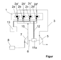
- FIG. 1 An embodiment of the invention is shown.
- the single figure shows a turbocharger with electric machine, the in Form of a generator converted electrical energy for driving Actuators used electromagnetic valves.
- the sole figure shows a turbocharger with an electric machine 11 a.
- From an internal combustion engine 1 arrive from the 4 cylinders 2a, 2b, 2c and 2d, whose valves 2a ', 2b', 2c 'and 2d' are electromagnetically controlled be, the exhaust gases through an exhaust tract 3 to a first paddle wheel 5 in the exhaust tract 3 of a turbocharger.
- By the exhaust gases is the first Paddle 5 offset in the exhaust tract 3 in a rotating movement.
- the first paddle wheel 5 in the exhaust tract 3 is a rotating shaft 6 fixed connected to which an electric machine 11a is mounted.
- Next is the rotating shaft 6 with a second impeller 7 in the intake tract 10th firmly connected.
- the electric motor 11a As long as the electric motor 11a is out of operation, it turns the first paddle wheel 5 in the exhaust tract 3 the faster, the more exhaust gases in the Exhaust tract 3 are. At the same time, this rotates with the first paddle wheel 5 via the rotating shaft 6 connected second impeller 7 in the intake 10 also faster.
- the electric machine 11a If the electric machine 11a is no longer increasing the rotational speed the rotating shaft 6 is needed, so are given second operating parameters of the internal combustion engine 1, takes the electric Machine 11a in the form of a generator of the rotating shaft. 6 mechanical rotational energy and converts it into electrical energy in order to allow the actuators of the electromagnetic valves 2a ', 2b', 2c ' and 2d 'to drive.
- the converted electrical energy of the electric Machine 11a is connected via a control line 12 directly to the individual actuating actuators the electromagnetic valves 2a ', 2b', 2c 'and 2d' of the cylinders 2a, 2b, 2c and 2d passed in the internal combustion engine 1 and serves to serves to move the electromagnetic valves 2a ', 2b', 2c 'and 2d'. If no electrical energy is available from the electric machine 11a, because these z. B. works as an electric motor, takes over an additional Power generator 13, the movement of the electromagnetic valves 2a ', 2b', 2c 'and 2d'. However, this can be done using the invention Procedure be dimensioned much smaller than before, since he only temporarily supplies the energy for the movement of the valves 2a ', 2b', 2c 'and 2d'.
Landscapes
- Engineering & Computer Science (AREA)
- Mechanical Engineering (AREA)
- General Engineering & Computer Science (AREA)
- Chemical & Material Sciences (AREA)
- Combustion & Propulsion (AREA)
- Supercharger (AREA)
Abstract
Description
Claims (1)
- Verfahren zum Antreiben eines Turboladers, der an einer Brennkraftmaschine in einem Kraftfahrzeug angebracht ist, mittels einer elektrischen Maschine, die an einer rotierenden Welle des Turboladers angebracht ist und abhängig von vorgegebenen ersten Betriebsparametern der Brennkraftmaschine in Form eines Elektromotors elektrische Energie zum Antreiben der rotierenden Welle abgibt, und abhängig von vorgegebenen zweiten Betriebsparametern der Brennkraftmaschine in Form eines Generators von der rotierenden Welle mechanische Rotations-Energie aufnimmt und in elektrische Energie wandelt, dadurch gekennzeichnet, dass die von der elektrischen Maschine (11a) gewandelte elektrische Energie zur Steuerung und/oder Regelung der Stell-Aktuatoren eines elektromagnetischen Ventiltriebs (2a',2b',2c',2d') der Brennkraftmaschine (1) verwendet wird.
Applications Claiming Priority (2)
| Application Number | Priority Date | Filing Date | Title |
|---|---|---|---|
| DE10332042A DE10332042B4 (de) | 2003-07-11 | 2003-07-11 | Verfahren zum Antreiben eines Turboladers |
| DE10332042 | 2003-07-11 |
Publications (2)
| Publication Number | Publication Date |
|---|---|
| EP1496215A1 true EP1496215A1 (de) | 2005-01-12 |
| EP1496215B1 EP1496215B1 (de) | 2006-08-23 |
Family
ID=33441757
Family Applications (1)
| Application Number | Title | Priority Date | Filing Date |
|---|---|---|---|
| EP04014707A Expired - Lifetime EP1496215B1 (de) | 2003-07-11 | 2004-06-22 | Verfahren zum Antreiben eines Turboladers |
Country Status (3)
| Country | Link |
|---|---|
| EP (1) | EP1496215B1 (de) |
| AT (1) | ATE337479T1 (de) |
| DE (2) | DE10332042B4 (de) |
Cited By (1)
| Publication number | Priority date | Publication date | Assignee | Title |
|---|---|---|---|---|
| DE102013223454A1 (de) * | 2013-11-18 | 2015-05-21 | Bosch Mahle Turbo Systems Gmbh & Co. Kg | Verfahren zum Steuern eines Ventilelements |
Citations (4)
| Publication number | Priority date | Publication date | Assignee | Title |
|---|---|---|---|---|
| EP0217537A1 (de) * | 1985-08-28 | 1987-04-08 | Isuzu Motors Limited | Kraftgenerator zur Benutzung mit einem Verbrennungsmotor |
| US5373827A (en) * | 1991-12-30 | 1994-12-20 | Kokusan Denki Co., Ltd. | Fuel injection equipment for internal combustion engine |
| DE19518317A1 (de) * | 1995-05-18 | 1996-11-21 | Gerhard Dr Ing Huber | Verfahren und Vorrichtung zum Betrieb eines elektrisch unterstützten Turboladers |
| US6158403A (en) * | 1999-03-30 | 2000-12-12 | Aura Systems, Inc. | Servo control system for an electromagnetic valve actuator used in an internal combustion engine |
Family Cites Families (2)
| Publication number | Priority date | Publication date | Assignee | Title |
|---|---|---|---|---|
| JPS63302131A (ja) * | 1987-05-30 | 1988-12-09 | Isuzu Motors Ltd | 回転電機付タ−ボチャ−ジャの制御装置 |
| DE10014756A1 (de) * | 2000-03-24 | 2001-10-04 | Bayerische Motoren Werke Ag | Vorrichtung und Verfahren zur Einstellung von Ventiltriebsfedern |
-
2003
- 2003-07-11 DE DE10332042A patent/DE10332042B4/de not_active Expired - Lifetime
-
2004
- 2004-06-22 AT AT04014707T patent/ATE337479T1/de not_active IP Right Cessation
- 2004-06-22 EP EP04014707A patent/EP1496215B1/de not_active Expired - Lifetime
- 2004-06-22 DE DE502004001249T patent/DE502004001249D1/de not_active Expired - Fee Related
Patent Citations (4)
| Publication number | Priority date | Publication date | Assignee | Title |
|---|---|---|---|---|
| EP0217537A1 (de) * | 1985-08-28 | 1987-04-08 | Isuzu Motors Limited | Kraftgenerator zur Benutzung mit einem Verbrennungsmotor |
| US5373827A (en) * | 1991-12-30 | 1994-12-20 | Kokusan Denki Co., Ltd. | Fuel injection equipment for internal combustion engine |
| DE19518317A1 (de) * | 1995-05-18 | 1996-11-21 | Gerhard Dr Ing Huber | Verfahren und Vorrichtung zum Betrieb eines elektrisch unterstützten Turboladers |
| US6158403A (en) * | 1999-03-30 | 2000-12-12 | Aura Systems, Inc. | Servo control system for an electromagnetic valve actuator used in an internal combustion engine |
Cited By (1)
| Publication number | Priority date | Publication date | Assignee | Title |
|---|---|---|---|---|
| DE102013223454A1 (de) * | 2013-11-18 | 2015-05-21 | Bosch Mahle Turbo Systems Gmbh & Co. Kg | Verfahren zum Steuern eines Ventilelements |
Also Published As
| Publication number | Publication date |
|---|---|
| EP1496215B1 (de) | 2006-08-23 |
| DE502004001249D1 (de) | 2006-10-05 |
| ATE337479T1 (de) | 2006-09-15 |
| DE10332042B4 (de) | 2007-08-09 |
| DE10332042A1 (de) | 2005-02-17 |
Similar Documents
| Publication | Publication Date | Title |
|---|---|---|
| EP1070837B1 (de) | Vorrichtung und Verfahren zur Leistungssteigerung einer mittels Abgasturboladers aufgeladenen Brennkraftmaschine | |
| EP0606316B1 (de) | Antriebsanordnung für ein kraftfahrzeug | |
| DE69001835T2 (de) | Energiezurueckgewinnungssystem fuer kraftfahrzeuge. | |
| DE69918342T2 (de) | Regelsystem für ein Hybridfahrzeug | |
| DE10063751A1 (de) | Verfahren zum Betrieb eines Verbrennungsmotors | |
| EP3026237A1 (de) | Verfahren und vorrichtung zum betrieb eines elektromotorisch unterstützten abgasturboladers eines kraftfahrzeugs | |
| DE102006019031A1 (de) | Verfahren zur Momentensteuerung einer Hybridantriebseinheit sowie Hybridantriebseinheit | |
| EP2547876A1 (de) | Verfahren und vorrichtung zum betreiben eines verbrennungsmotors bei einer störung eines kurbelwellensensors | |
| EP3051097B1 (de) | Motorbremsverfahren für eine aufgeladene brennkraftmaschine und vorrichtung zur modulation einer motorbremsleistung eines kraftfahrzeugs mit aufgeladener brennkraftmaschine | |
| DE10159801A1 (de) | Verbrennungsmotor und Verfahren zum Betreiben eines Verbrennungsmotors | |
| DE10062985A1 (de) | Verfahren und Steuereinrichtung zum Bestimmen des Kurbelwellenwinkels von einer Brennkraftmaschine sowie Antriebsstrang | |
| DE4109379A1 (de) | Kraftfahrzeugantrieb | |
| DE102005008156A1 (de) | Verfahren zum Betreiben eines Hybridantriebsystems und Vorrichtung zur Durchführung des Verfahrens | |
| DE10332043B4 (de) | Antriebssystem für Turbolader mit elektrischer Maschine | |
| EP1496215B1 (de) | Verfahren zum Antreiben eines Turboladers | |
| DE69614082T2 (de) | Antriebseinheit eines Fahrzeuges und entsprechendes Regelungsverfahren | |
| DE102010025196B4 (de) | Verfahren zum Betreiben einer Brennkraftmaschine mit Nutzturbine in einem Wastegate-Kanal und Brennkraftmaschine mit Nutzturbine in einem Wastegate-Kanal | |
| DE10232805B4 (de) | Startergeneratorvorrichtung und Verfahren zum Steuern einer Startergeneratorvorrichtung bei einem Kraftfahrzeug | |
| EP1531074B1 (de) | Hybridfahrzeug mit Geschwindigkeitsregler | |
| DE102007000312B4 (de) | Steuergerät eines Fahrzeugverbrennungsmotorsystems | |
| EP3244044B1 (de) | Verfahren zum betreiben einer brennkraftmaschine, insbesondere als antriebseinrichtung für ein fahrzeug | |
| DE102013209572A1 (de) | Vermeidung der rauchgrenze bei einem hybrid-diesel/elektro-antriebsstrang | |
| DE112019001382T5 (de) | Steuergerät und steuerverfahren | |
| EP2030856A1 (de) | Verfahren und zur Ausführung des Verfahrens notwendige Vorrichtung zur Erhöhung der Effizienz eines Antriebs eines Fahrzeuges | |
| DE10201930A1 (de) | Kraftfahrzeug mit einer Brennkraftmaschine und einem Brennstoffzellensystem |
Legal Events
| Date | Code | Title | Description |
|---|---|---|---|
| PUAI | Public reference made under article 153(3) epc to a published international application that has entered the european phase |
Free format text: ORIGINAL CODE: 0009012 |
|
| AK | Designated contracting states |
Kind code of ref document: A1 Designated state(s): AT BE BG CH CY CZ DE DK EE ES FI FR GB GR HU IE IT LI LU MC NL PL PT RO SE SI SK TR |
|
| AX | Request for extension of the european patent |
Extension state: AL HR LT LV MK |
|
| 17P | Request for examination filed |
Effective date: 20050503 |
|
| AKX | Designation fees paid |
Designated state(s): AT BE BG CH CY CZ DE DK EE ES FI FR GB GR HU IE IT LI LU MC NL PL PT RO SE SI SK TR |
|
| GRAP | Despatch of communication of intention to grant a patent |
Free format text: ORIGINAL CODE: EPIDOSNIGR1 |
|
| GRAS | Grant fee paid |
Free format text: ORIGINAL CODE: EPIDOSNIGR3 |
|
| GRAA | (expected) grant |
Free format text: ORIGINAL CODE: 0009210 |
|
| AK | Designated contracting states |
Kind code of ref document: B1 Designated state(s): AT BE BG CH CY CZ DE DK EE ES FI FR GB GR HU IE IT LI LU MC NL PL PT RO SE SI SK TR |
|
| PG25 | Lapsed in a contracting state [announced via postgrant information from national office to epo] |
Ref country code: IT Free format text: LAPSE BECAUSE OF FAILURE TO SUBMIT A TRANSLATION OF THE DESCRIPTION OR TO PAY THE FEE WITHIN THE PRESCRIBED TIME-LIMIT;WARNING: LAPSES OF ITALIAN PATENTS WITH EFFECTIVE DATE BEFORE 2007 MAY HAVE OCCURRED AT ANY TIME BEFORE 2007. THE CORRECT EFFECTIVE DATE MAY BE DIFFERENT FROM THE ONE RECORDED. Effective date: 20060823 Ref country code: PL Free format text: LAPSE BECAUSE OF FAILURE TO SUBMIT A TRANSLATION OF THE DESCRIPTION OR TO PAY THE FEE WITHIN THE PRESCRIBED TIME-LIMIT Effective date: 20060823 Ref country code: IE Free format text: LAPSE BECAUSE OF FAILURE TO SUBMIT A TRANSLATION OF THE DESCRIPTION OR TO PAY THE FEE WITHIN THE PRESCRIBED TIME-LIMIT Effective date: 20060823 Ref country code: SK Free format text: LAPSE BECAUSE OF FAILURE TO SUBMIT A TRANSLATION OF THE DESCRIPTION OR TO PAY THE FEE WITHIN THE PRESCRIBED TIME-LIMIT Effective date: 20060823 Ref country code: SI Free format text: LAPSE BECAUSE OF FAILURE TO SUBMIT A TRANSLATION OF THE DESCRIPTION OR TO PAY THE FEE WITHIN THE PRESCRIBED TIME-LIMIT Effective date: 20060823 Ref country code: FI Free format text: LAPSE BECAUSE OF FAILURE TO SUBMIT A TRANSLATION OF THE DESCRIPTION OR TO PAY THE FEE WITHIN THE PRESCRIBED TIME-LIMIT Effective date: 20060823 Ref country code: RO Free format text: LAPSE BECAUSE OF FAILURE TO SUBMIT A TRANSLATION OF THE DESCRIPTION OR TO PAY THE FEE WITHIN THE PRESCRIBED TIME-LIMIT Effective date: 20060823 Ref country code: CZ Free format text: LAPSE BECAUSE OF FAILURE TO SUBMIT A TRANSLATION OF THE DESCRIPTION OR TO PAY THE FEE WITHIN THE PRESCRIBED TIME-LIMIT Effective date: 20060823 Ref country code: NL Free format text: LAPSE BECAUSE OF FAILURE TO SUBMIT A TRANSLATION OF THE DESCRIPTION OR TO PAY THE FEE WITHIN THE PRESCRIBED TIME-LIMIT Effective date: 20060823 |
|
| REG | Reference to a national code |
Ref country code: GB Ref legal event code: FG4D Free format text: NOT ENGLISH |
|
| REG | Reference to a national code |
Ref country code: CH Ref legal event code: EP |
|
| REG | Reference to a national code |
Ref country code: IE Ref legal event code: FG4D Free format text: LANGUAGE OF EP DOCUMENT: GERMAN |
|
| REF | Corresponds to: |
Ref document number: 502004001249 Country of ref document: DE Date of ref document: 20061005 Kind code of ref document: P |
|
| GBT | Gb: translation of ep patent filed (gb section 77(6)(a)/1977) |
Effective date: 20061004 |
|
| PG25 | Lapsed in a contracting state [announced via postgrant information from national office to epo] |
Ref country code: BG Free format text: LAPSE BECAUSE OF FAILURE TO SUBMIT A TRANSLATION OF THE DESCRIPTION OR TO PAY THE FEE WITHIN THE PRESCRIBED TIME-LIMIT Effective date: 20061123 Ref country code: SE Free format text: LAPSE BECAUSE OF FAILURE TO SUBMIT A TRANSLATION OF THE DESCRIPTION OR TO PAY THE FEE WITHIN THE PRESCRIBED TIME-LIMIT Effective date: 20061123 Ref country code: DK Free format text: LAPSE BECAUSE OF FAILURE TO SUBMIT A TRANSLATION OF THE DESCRIPTION OR TO PAY THE FEE WITHIN THE PRESCRIBED TIME-LIMIT Effective date: 20061123 |
|
| PG25 | Lapsed in a contracting state [announced via postgrant information from national office to epo] |
Ref country code: ES Free format text: LAPSE BECAUSE OF FAILURE TO SUBMIT A TRANSLATION OF THE DESCRIPTION OR TO PAY THE FEE WITHIN THE PRESCRIBED TIME-LIMIT Effective date: 20061204 |
|
| ET | Fr: translation filed | ||
| PG25 | Lapsed in a contracting state [announced via postgrant information from national office to epo] |
Ref country code: PT Free format text: LAPSE BECAUSE OF FAILURE TO SUBMIT A TRANSLATION OF THE DESCRIPTION OR TO PAY THE FEE WITHIN THE PRESCRIBED TIME-LIMIT Effective date: 20070125 |
|
| NLV1 | Nl: lapsed or annulled due to failure to fulfill the requirements of art. 29p and 29m of the patents act | ||
| REG | Reference to a national code |
Ref country code: IE Ref legal event code: FD4D |
|
| PLBE | No opposition filed within time limit |
Free format text: ORIGINAL CODE: 0009261 |
|
| STAA | Information on the status of an ep patent application or granted ep patent |
Free format text: STATUS: NO OPPOSITION FILED WITHIN TIME LIMIT |
|
| 26N | No opposition filed |
Effective date: 20070524 |
|
| BERE | Be: lapsed |
Owner name: BAYERISCHE MOTOREN WERKE A.G. Effective date: 20070630 |
|
| PG25 | Lapsed in a contracting state [announced via postgrant information from national office to epo] |
Ref country code: MC Free format text: LAPSE BECAUSE OF NON-PAYMENT OF DUE FEES Effective date: 20070630 |
|
| PG25 | Lapsed in a contracting state [announced via postgrant information from national office to epo] |
Ref country code: BE Free format text: LAPSE BECAUSE OF NON-PAYMENT OF DUE FEES Effective date: 20070630 |
|
| PG25 | Lapsed in a contracting state [announced via postgrant information from national office to epo] |
Ref country code: GR Free format text: LAPSE BECAUSE OF FAILURE TO SUBMIT A TRANSLATION OF THE DESCRIPTION OR TO PAY THE FEE WITHIN THE PRESCRIBED TIME-LIMIT Effective date: 20061124 |
|
| PG25 | Lapsed in a contracting state [announced via postgrant information from national office to epo] |
Ref country code: EE Free format text: LAPSE BECAUSE OF FAILURE TO SUBMIT A TRANSLATION OF THE DESCRIPTION OR TO PAY THE FEE WITHIN THE PRESCRIBED TIME-LIMIT Effective date: 20060823 |
|
| PG25 | Lapsed in a contracting state [announced via postgrant information from national office to epo] |
Ref country code: AT Free format text: LAPSE BECAUSE OF NON-PAYMENT OF DUE FEES Effective date: 20070622 |
|
| PGFP | Annual fee paid to national office [announced via postgrant information from national office to epo] |
Ref country code: IT Payment date: 20080625 Year of fee payment: 5 |
|
| PGRI | Patent reinstated in contracting state [announced from national office to epo] |
Ref country code: IT Effective date: 20080801 |
|
| PGFP | Annual fee paid to national office [announced via postgrant information from national office to epo] |
Ref country code: GB Payment date: 20080626 Year of fee payment: 5 |
|
| REG | Reference to a national code |
Ref country code: CH Ref legal event code: PL |
|
| PG25 | Lapsed in a contracting state [announced via postgrant information from national office to epo] |
Ref country code: LI Free format text: LAPSE BECAUSE OF NON-PAYMENT OF DUE FEES Effective date: 20080630 Ref country code: CH Free format text: LAPSE BECAUSE OF NON-PAYMENT OF DUE FEES Effective date: 20080630 |
|
| PG25 | Lapsed in a contracting state [announced via postgrant information from national office to epo] |
Ref country code: LU Free format text: LAPSE BECAUSE OF NON-PAYMENT OF DUE FEES Effective date: 20070622 Ref country code: CY Free format text: LAPSE BECAUSE OF FAILURE TO SUBMIT A TRANSLATION OF THE DESCRIPTION OR TO PAY THE FEE WITHIN THE PRESCRIBED TIME-LIMIT Effective date: 20060823 |
|
| PG25 | Lapsed in a contracting state [announced via postgrant information from national office to epo] |
Ref country code: TR Free format text: LAPSE BECAUSE OF FAILURE TO SUBMIT A TRANSLATION OF THE DESCRIPTION OR TO PAY THE FEE WITHIN THE PRESCRIBED TIME-LIMIT Effective date: 20060823 Ref country code: HU Free format text: LAPSE BECAUSE OF FAILURE TO SUBMIT A TRANSLATION OF THE DESCRIPTION OR TO PAY THE FEE WITHIN THE PRESCRIBED TIME-LIMIT Effective date: 20070224 |
|
| PGFP | Annual fee paid to national office [announced via postgrant information from national office to epo] |
Ref country code: FR Payment date: 20090625 Year of fee payment: 6 |
|
| PGFP | Annual fee paid to national office [announced via postgrant information from national office to epo] |
Ref country code: DE Payment date: 20090725 Year of fee payment: 6 |
|
| GBPC | Gb: european patent ceased through non-payment of renewal fee |
Effective date: 20090622 |
|
| PG25 | Lapsed in a contracting state [announced via postgrant information from national office to epo] |
Ref country code: GB Free format text: LAPSE BECAUSE OF NON-PAYMENT OF DUE FEES Effective date: 20090622 |
|
| REG | Reference to a national code |
Ref country code: FR Ref legal event code: ST Effective date: 20110228 |
|
| PG25 | Lapsed in a contracting state [announced via postgrant information from national office to epo] |
Ref country code: IT Free format text: LAPSE BECAUSE OF NON-PAYMENT OF DUE FEES Effective date: 20090622 |
|
| PG25 | Lapsed in a contracting state [announced via postgrant information from national office to epo] |
Ref country code: DE Free format text: LAPSE BECAUSE OF NON-PAYMENT OF DUE FEES Effective date: 20110101 |
|
| PG25 | Lapsed in a contracting state [announced via postgrant information from national office to epo] |
Ref country code: FR Free format text: LAPSE BECAUSE OF NON-PAYMENT OF DUE FEES Effective date: 20100630 |