EP1495836A1 - Lens grinding apparatus - Google Patents
Lens grinding apparatus Download PDFInfo
- Publication number
- EP1495836A1 EP1495836A1 EP04077741A EP04077741A EP1495836A1 EP 1495836 A1 EP1495836 A1 EP 1495836A1 EP 04077741 A EP04077741 A EP 04077741A EP 04077741 A EP04077741 A EP 04077741A EP 1495836 A1 EP1495836 A1 EP 1495836A1
- Authority
- EP
- European Patent Office
- Prior art keywords
- grinding
- grinding water
- water
- wastes
- hose
- Prior art date
- Legal status (The legal status is an assumption and is not a legal conclusion. Google has not performed a legal analysis and makes no representation as to the accuracy of the status listed.)
- Granted
Links
- XLYOFNOQVPJJNP-UHFFFAOYSA-N water Substances O XLYOFNOQVPJJNP-UHFFFAOYSA-N 0.000 claims abstract description 572
- 239000006260 foam Substances 0.000 claims abstract description 45
- 238000002347 injection Methods 0.000 claims abstract description 27
- 239000007924 injection Substances 0.000 claims abstract description 27
- 239000011521 glass Substances 0.000 claims abstract description 18
- 239000002699 waste material Substances 0.000 description 120
- 239000008213 purified water Substances 0.000 description 115
- 230000001877 deodorizing effect Effects 0.000 description 57
- 238000004891 communication Methods 0.000 description 32
- 238000010276 construction Methods 0.000 description 29
- 238000001914 filtration Methods 0.000 description 24
- 238000010586 diagram Methods 0.000 description 16
- 238000005192 partition Methods 0.000 description 10
- 238000005406 washing Methods 0.000 description 8
- 230000004048 modification Effects 0.000 description 7
- 238000012986 modification Methods 0.000 description 7
- OKTJSMMVPCPJKN-UHFFFAOYSA-N Carbon Chemical compound [C] OKTJSMMVPCPJKN-UHFFFAOYSA-N 0.000 description 6
- 230000007423 decrease Effects 0.000 description 4
- 230000018044 dehydration Effects 0.000 description 4
- 238000006297 dehydration reaction Methods 0.000 description 4
- 238000011156 evaluation Methods 0.000 description 4
- 239000000203 mixture Substances 0.000 description 4
- 238000000926 separation method Methods 0.000 description 4
- 230000000903 blocking effect Effects 0.000 description 3
- 238000004332 deodorization Methods 0.000 description 3
- 238000000034 method Methods 0.000 description 3
- 238000012856 packing Methods 0.000 description 3
- 239000007921 spray Substances 0.000 description 3
- 230000015572 biosynthetic process Effects 0.000 description 2
- 230000009467 reduction Effects 0.000 description 2
- 239000002351 wastewater Substances 0.000 description 2
- 230000009471 action Effects 0.000 description 1
- 239000002518 antifoaming agent Substances 0.000 description 1
- 230000008033 biological extinction Effects 0.000 description 1
- 230000008859 change Effects 0.000 description 1
- 238000001816 cooling Methods 0.000 description 1
- 230000003247 decreasing effect Effects 0.000 description 1
- 238000001514 detection method Methods 0.000 description 1
- 239000000428 dust Substances 0.000 description 1
- 230000000694 effects Effects 0.000 description 1
- 239000005357 flat glass Substances 0.000 description 1
- JEGUKCSWCFPDGT-UHFFFAOYSA-N h2o hydrate Chemical compound O.O JEGUKCSWCFPDGT-UHFFFAOYSA-N 0.000 description 1
- 230000002093 peripheral effect Effects 0.000 description 1
- 230000008569 process Effects 0.000 description 1
- 239000010865 sewage Substances 0.000 description 1
Images




Classifications
-
- B—PERFORMING OPERATIONS; TRANSPORTING
- B24—GRINDING; POLISHING
- B24B—MACHINES, DEVICES, OR PROCESSES FOR GRINDING OR POLISHING; DRESSING OR CONDITIONING OF ABRADING SURFACES; FEEDING OF GRINDING, POLISHING, OR LAPPING AGENTS
- B24B55/00—Safety devices for grinding or polishing machines; Accessories fitted to grinding or polishing machines for keeping tools or parts of the machine in good working condition
- B24B55/06—Dust extraction equipment on grinding or polishing machines
-
- B—PERFORMING OPERATIONS; TRANSPORTING
- B24—GRINDING; POLISHING
- B24B—MACHINES, DEVICES, OR PROCESSES FOR GRINDING OR POLISHING; DRESSING OR CONDITIONING OF ABRADING SURFACES; FEEDING OF GRINDING, POLISHING, OR LAPPING AGENTS
- B24B55/00—Safety devices for grinding or polishing machines; Accessories fitted to grinding or polishing machines for keeping tools or parts of the machine in good working condition
- B24B55/02—Equipment for cooling the grinding surfaces, e.g. devices for feeding coolant
-
- B—PERFORMING OPERATIONS; TRANSPORTING
- B24—GRINDING; POLISHING
- B24B—MACHINES, DEVICES, OR PROCESSES FOR GRINDING OR POLISHING; DRESSING OR CONDITIONING OF ABRADING SURFACES; FEEDING OF GRINDING, POLISHING, OR LAPPING AGENTS
- B24B9/00—Machines or devices designed for grinding edges or bevels on work or for removing burrs; Accessories therefor
- B24B9/02—Machines or devices designed for grinding edges or bevels on work or for removing burrs; Accessories therefor characterised by a special design with respect to properties of materials specific to articles to be ground
- B24B9/06—Machines or devices designed for grinding edges or bevels on work or for removing burrs; Accessories therefor characterised by a special design with respect to properties of materials specific to articles to be ground of non-metallic inorganic material, e.g. stone, ceramics, porcelain
- B24B9/08—Machines or devices designed for grinding edges or bevels on work or for removing burrs; Accessories therefor characterised by a special design with respect to properties of materials specific to articles to be ground of non-metallic inorganic material, e.g. stone, ceramics, porcelain of glass
- B24B9/14—Machines or devices designed for grinding edges or bevels on work or for removing burrs; Accessories therefor characterised by a special design with respect to properties of materials specific to articles to be ground of non-metallic inorganic material, e.g. stone, ceramics, porcelain of glass of optical work, e.g. lenses, prisms
- B24B9/146—Accessories, e.g. lens mounting devices
Definitions
- the present invention relates to a lens grinding apparatus having a grinding water storage vessel.
- a grinding water treating means which filters grinding water after used in a glasses lens grinding work to separate grinding wastes and produce purified water and a deodorizing means for removing an offensive smell developed in the grinding water treating means and also developed in a grinding water storage vessel, are disposed within different housings respectively.
- a housing which contains therein the grinding water treating means, a housing which houses therein the deodorizing means, as well as a space present above the grinding water storage vessel and a housing with the deodorizing means disposed therein, are interconnected through hoses or pipes. In this case, an offensive smell is removed through hoses or the like which connect the housings.
- the size of the grinding water treating apparatus becomes large, thus giving rise to the problem that it is difficult to accommodate the apparatus within a limited receptacle space.
- a lens grinding apparatus having a defoaming device which injects grinding water containing a defoaming agent toward the foams in the form of spray (shower) to remove the foams
- a lens grinding apparatus having a defoaming device which injects pressurized grinding water upward from below the level of already-stored grinding water with use of an injection nozzle connected to the grinding water storage vessel
- a lens grinding apparatus having a foam suction means which sucks the foams developed on the surface of grinding water
- a lens grinding apparatus wherein a foam overflow path for overflowing the foams developed on the grinding water surface is provided in the grinding water storage vessel.
- the present invention has been accomplished in view of the above mentioned problems in the conventional apparatuses and it is an object of the present invention to provide a lens grinding apparatus capable of suppressing the formation of foams when grinding water flowing into a grinding water storage vessel mixes into grinding water already stored in the vessel.
- a lens grinding apparatus comprising a grinding water storage vessel for the storage of grinding water which has been used in grinding a glasses lens and a grinding water supply hose for allowing the grinding water to flow into the grinding water storage vessel, wherein an injection means is provided at a tip portion of the grinding water supply hose to inject the grinding water radially, thereby allowing the grinding water to cover the surface of the grinding water already stored in the grinding water storage vessel and extinguishing foams formed on the .surface of the grinding water.
- reference numeral 1 denotes a lens grinding apparatus
- numeral 2 denotes an apparatus support base for supporting the lens grinding apparatus
- numeral 3 denotes a grinding water tank (grinding water storage vessel) disposed under the apparatus support base 2.
- a grinding water supply pump 4 is installed in the interior of the grinding water tank 3.
- Numerals 4a and 4b denote a suction port and a discharge port, respectively, of the grinding water supply pump 4.
- One port 5a of a three-way change-over valve 5 is connected to the discharge port 4b of the grinding water supply pump 4.
- Numerals 5b and 5c denote the other two ports of the three-way change-over valve 5 and numeral 5d denotes a change-over lever in the three-way change-over valve 5.
- the ports 5a and 5b come into communication with each other and at the same time the communications between the ports 5a, 5b and the port 5c are cut off.
- the ports 5a and 5c come into communication with each other and at the same time the communications between the ports 5a, 5c and the port 5b are cut off.
- a support base 6 as a housing is disposed sideways of the apparatus support base 2.
- a grinding water treating apparatus 7 On the support base 6 is mounted a grinding water treating apparatus 7, while under the support base 6 is disposed a grinding water storage vessel 8 (e.g., a bucket).
- the grinding water treating apparatus 7 is provided with a grinding water treating means and a deodorizing means.
- a grinding water treating section (grinding water treating means) 7a has a bottomed, cylindrical, transparent (or translucent) separating vessel body (pressure-resistant vessel) 9, a bottomed, cylindrical, transparent (or translucent) grinding wastes separating filter 10 (one-pass treating means) disposed within the separating vessel body 9, a lid 11 which closes an upper-end opening of the separating vessel body 9, a packing 12 interposed between the lid 11 and the separating vessel body 9, fixing screws 13 which fix the lid 11 to the separating vessel body 9, and a lever 14 for performing the fixing operation of the fixing screws 13 and for cancelling the same operation.
- the grinding water treating section 7a is further provided with a feed port 15 connected to the upper end portion of the separating vessel body 9, a drain port 16 formed in a bottom of the separating vessel body 9, and a three-way change-over valve 17 one port 17a of which is connected to the feed port 15.
- Numerals 17b and 17c denote the other two ports of the three-way change-over valve 17, and numeral 17d denotes a change-over lever in the three-way change-over valve 17.
- the ports 17a and 17b come into communication with each other and at the same time the communications between the ports 17a, 17b and the port 17c are cut off. Further, by switching the change-over lever 17d in the three-way change-over valve 17 to the port 17c side the ports 17a and 17c come into communication with each other and at the same time the communications between the ports 17a, 17c and the port 17b are cut off.
- a grinding water supply nozzle (not shown), which is disposed within the lens grinding apparatus 1, is connected to the port 5b of the three-way change-over valve 5 through a grinding water supply hose 18.
- a grinding wheel (not shown) is rotated at high speed to grind a lens to be ground (unground circular glasses lens) into a glasses lens shape (globe shape).
- the grinding water stored in the grinding water tank 3 is pumped up by the grinding water supply pump 4 and is fed to the nozzle (not shown) in the lens grinding apparatus 1 through both three-way change-over valve 5 and grinding water supply hose 18, then is, fed from the nozzle to a lens grinding section using the grinding wheel to cool the grinding section and wash away grinding wastes.
- the nozzle not shown
- grinding water supply pump 4 For the grinding work there is used a known construction, so the details thereof will here be omitted.
- the grinding water which has thus washed away the grinding wastes is allowed to flow down together with the grinding wastes through a bottom of the lens grinding apparatus 1 and further through a drain hose 19 into the grinding water tank 3.
- an air compressor (a pressurizing means, a compressed air supply means, i.e., a compressed gas supply means) 20 is connected to the port 17b of the three-way change-over valve 17 through an air hose 21, and the port 5c of the three-way change-over valve 5 and the port 17c of the three-way change-over valve 17 are connected together through a grinding water supply hose 22.
- the grinding water supply hose 22 is attached to the port 17c removably.
- the deodorizing means is a deodorizing device (not shown) disposed in a space formed, for example, under the grinding water treating section 7a and inside the support base 6.
- the change-over lever 5d of the three-way change-over valve 5 is switched to the port 5b side, allowing the ports 5a and 5b to come into communication with each other and blocking the communication between the ports 5a, 5b and the port 5c.
- the grinding wheel (not shown) in the lens grinding apparatus 1 is rotated at high speed to grind the to-be-ground lens into a glasses lens shape (globe shape).
- the grinding water stored in the grinding water tank 3 is pumped up by the grinding water supply pump 4 and is fed to the nozzle (not shown) in the lens grinding apparatus 1 through the three-way change-over valve 5 and the grinding water supply hose 18, then is fed from the nozzle to the lens grinding section using the grinding wheel to cool the grinding section and wash away grinding wastes.
- the grinding water which has thus washed away the grinding wastes is allowed to flow down together with the grinding wastes from the bottom of the lens grinding apparatus 1 to the grinding water tank 3 through the drain hose 19.
- the grinding water supply pump 4 is activated to supply the grinding water stored in the grinding water tank 3, together with grinding wastes, into the grinding wastes separating filter 10 in the grinding water treating apparatus 7 through the three-way change-over valve 5, grinding water supply hose 22 and three-way change-over valve 17.
- the grinding water passes through the grinding wastes separating filter 10, flows down from the drain port 16 and is stored in the grinding water storage vessel 8.
- the grinding wastes contained in the grinding water are collected by the grinding wastes separating filter 10.
- an intra-vessel sensor (not shown) is disposed in an upper portion (e.g., on a lower surface of the lid 11) within the separating vessel body 9 to detect a clogged state of the grinding wastes separating filter 10, and when the internal pressure of the filter 10 has become higher than a predetermined value, this state is displayed for example by an LED (not shown) on the basis of a pressure detection signal provided from the intra-vessel pressure sensor (not shown) to let a worker know this state.
- the change-over lever 17d of the three-way change-over valve 17 is switched to the port 17b side to establish communication between the ports 17a and 17b and block communications between the ports 17a, 17b and the port 17c.
- the air compressor 20 is turned ON to supply compressed air to above the grinding wastes separating filter 10 through the air hose 21 and the three-way change-over valve 17.
- the air compressor 20 When there is little grinding water flowing down from the drain port 16, the air compressor 20 is turned OFF and the fixed state of the lid 11 to the separating vessel body 9 by the fixing screws 13 is cancelled by operating the lever 14. Thereafter, the lid 11 is removed from the separating vessel body 9, the grinding wastes separating filter 10 is taken out from the interior of the separating vessel body, and the grinding wastes present within the filter 10 are discarded.
- the grinding water present in the grinding water storage vessel 8 is returned to the grinding water tank 3 for use in the grinding work, while when the degree of turbidity is high, the grinding water is discarded by flowing it to sewage for example.
- Turbid grinding water and grinding wastes present in the grinding water tank 3 are treated by repeating such a process.
- a turbidity sensor for detecting the state of turbidity in the interior of the grinding water tank 3 is provided, and when a somewhat progressed state of turbidity is detected by the turbidity sensor, the state of connection of each port in the three-way change-over valve 5 and 17 is switched over automatically in the same way as above and there is performed the grinding wastes separating work by the grinding water treating apparatus 7.
- the grinding water treating apparatus (7) is provided with the grinding water treating means (grinding water treating section 7a) which filters grinding water having been used in the lens grinding work to separate grinding wastes and produce purified water and the deodorizing means (deodorizing device (not shown)) for removing an offensive smell present in the interior of the grinding water treating means (7a) and the grinding water storage vessel (storage tank 3), the grinding water treating means (7a) and the deodorizing means (not shown) being disposed within the same housing (support base 6).
- the grinding water treating means grinding water treating section 7a
- the deodorizing device not shown
- the grinding water treating apparatus (7) provided with both grinding water treating means (7a) and deodorizing means (not shown) can be accommodated within a limited receptacle space and hence it is possible to reduce the receptacle space.
- the grinding water treating means (7a) has a one-pass treating means (the grinding wastes separating filter 10) for passing grinding water once therethrough to filter off grinding wastes.
- grinding water (purified water) after the filtration does not return to the grinding water storage vessel (3), but filtered water high in clarity can be drained directly to the sewerage.
- the one-pass treating means (10) has a pressurizing means (the air compressor 20) which applies a predetermined pressure to the grinding water treating means (7a) to squeeze out and filter grinding water from grinding wastes present within the grinding water treating means (7a), thereby permitting the grinding wastes to be treated at a time.
- a pressurizing means the air compressor 20
- the grinding water present therein can be separated from the grinding wastes quickly, easily and positively, permitting easy discard of only the grinding wastes.
- the numeral 1 denotes a lens grinding apparatus
- numeral 2 denotes an apparatus support base for supporting the lens grinding apparatus
- numeral 3 denotes a grinding water tank (grinding water storage vessel) disposed under the apparatus support base 2.
- a partition filter 23 With a partition filter 23, the interior of the grinding water tank 3 is partitioned into a purified grinding water chamber (purified water chamber) 3a and a discharged grinding water chamber (waste water chamber) 3b.
- a purified water recycle pump 24 In the purified grinding water chamber 3a is disposed a purified water recycle pump 24, while in the discharged grinding water chamber 3b is disposed a discharged grinding water pump 25.
- a discharge side of the purified water recycle pump 24 and a grinding water supply nozzle (not shown) disposed within the lens grinding apparatus 1 are connected together through a purified grinding water supply hose 26.
- a grinding wheel (not shown) is rotated at high speed to grind a lens to be ground (unground circular glasses lens) into a glasses lens shape (globe shape).
- purified water present within the purified grinding water chamber 3a is pumped up by the purified water recycle pump 24 and is fed through the purified grinding water supply hose 26 to the nozzle (not shown) disposed within the lens grinding apparatus 1, then is fed from this nozzle to a lens grinding section using the grinding wheel to cool the grinding section and wash away grinding wastes.
- the purified water recycle pump 24 is fed through the purified grinding water supply hose 26 to the nozzle (not shown) disposed within the lens grinding apparatus 1, then is fed from this nozzle to a lens grinding section using the grinding wheel to cool the grinding section and wash away grinding wastes.
- grinding water discharged grinding water
- grinding water supply hose grinding water supply hose
- a grinding water treating apparatus 27 which is installed. on a support base (housing) 28 with caster.
- the grinding water treating apparatus 27 is provided with a grinding water treating means which filters discharged grinding water to separate grinding wastes and produce purified grinding water ("purified water” hereinafter) and a deodorizing means for removing an offensive smell developed within the grinding water treating means, etc.
- a grinding water treating section (grinding water treating means) 27a has a bottomed cylindrical separating vessel body (pressure-resistant vessel) 9 and a bottomed cylindrical grinding wastes separating filter (one-pass means) 10 disposed within the separating vessel body 9.
- the grinding water treating section 27a is also provided with a lid 11 which closes an upper-end opening of the separating vessel body 9, a packing 12 interposed between the lid 11 and the upper end of the separating vessel body 9, fixing screws 13 which fix the lid 11 to the separating vessel body 9, and a lever 14 for performing the fixing operation of the fixing screws 13 and cancelling the same operation.
- the grinding water treating section 27a is further provided with a feed port 15 connected to the upper end portion of the separating vessel body 9 and a drain port 16 provided in a lower portion of the separating vessel body 9.
- An opening/closing valve (not shown) is provided in each of the feed port 15 and drain port 16.
- Numerals 15a and 16a denote open/close operating lever for the opening/closing valve (not shown) in the feed port 15 and drain port 16.
- One end of a grinding water discharge hose 30 is connected to a discharge port (not shown) of the grinding water discharge pump 25, while an opposite end of the grinding water discharge hose 30 is connected to the feed port 15 removably with use of a connector or a screw.
- one end of a purified water recycle hose 31 is connected to the drain port 16 removably with use of a connector or a screw and an opposite end thereof is held in an upper portion of the purified grinding water chamber 3a in the grinding water tank 3 removably with use of a connector or a screw.
- fixing means for the connector or screw there may be used a known connector or nut used for the connection of hose.
- the deodorizing means has a deodorizing device 32 (see FIG. 3) disposed under the separating vessel body 9.
- the opening/closing valves (not shown) disposed in the feed port 15 and the drain port 16 are opened by operating the open/close operating levers 15a and 16a and in this state a grinding wheel (not shown) in the lens grinding apparatus 1 is rotated at high speed to grind a to-be-ground lens into a glasses lens shape (globe shape).
- purified water present within the purified grinding water chamber 3a in the purified water tank 3 is pumped up by the purified water recycle pump 24 and is fed through the purified grinding water supply hose 26 to the nozzle (not shown) disposed within the lens grinding apparatus 1, then is fed from the nozzle to the lens grinding section using the grinding wheel to cool the grinding section and wash away grinding wastes.
- the purified water after thus washing away of grinding wastes becomes discharged grinding water and is allowed to flow down together with the grinding wastes from the bottom of the lens grinding apparatus 1 into the discharged grinding water chamber 3b in the grinding water tank 3 through the grinding water discharge hose 19.
- the grinding water discharge pump 25 sucks the discharged grinding water from the interior of the discharged grinding water chamber 3b in the grinding water tank 3 together with grinding wastes and supplies the discharged grinding water containing the grinding wastes into the grinding wastes separating filter 10 through the grinding water discharge hose 30 and the feed port 15.
- a single pump may be used in common to both purified water recycle pump 24 and grinding water discharge pump 25.
- the discharged grinding water is separated from the grinding wastes by the grinding wastes separating filter 10 and becomes purified water, which is returned into the purified grinding water chamber 3a in the grinding water tank 3 through the drain port 16 and the purified water recycle hose 31.
- the grinding wastes separating filter 10 collects the grinding wastes contained in the discharged grinding water.
- the purified water recycle pump 24 and the grinding water discharge pump 25 are turned OFF and thereafter the lever 14 is operated to cancel the fixed state of the lid 11 to the separating vessel body 9 by the fixing screws 13.
- the lid 11 is removed from the separating vessel body 9, the grinding wastes separating filter 10 is taken out from the interior of the separating vessel body 9, and the grinding wastes collected in the filter 10 are discarded. Then, the filter 10 is returned to the separating vessel body 9 and the vessel body 9 is closed with the lid 11 by reversing the above operation, thereafter, the foregoing "grinding work” and “grinding water treatmen” are allowed to proceed. Subsequently, such a grinding water-grinding wastes separating work is performed repeatedly.
- the grinding wastes collected by the grinding wastes separating filter 10 may be discarded as described above after squeezing out purified water from the grinding wastes by the air compressor (pressurizing means) (not shown) and subsequent drainage thereof from the drain port 16.
- the purified water is somewhat turbid even after the application of such a grinding water treatment, there may be adopted a method involving removing the purified water recycle hose 31 from the grinding water tank 3, connecting the hose 31 to a sewer (not shown), and carrying out the foregoing grinding water treatment, whereby purified water free of grinding wastes can be discarded to the sewer.
- a method wherein the purified water recycle hose 31 is disconnected from the drain port 16, while a drain hose (not shown) connected to the sewer is attached to the drain port 16, and the foregoing grinding water treatment is carried out, thereby allowing turbid purified water free of grinding wastes to be discharged to the sewer.
- the deodorizing device 32 it is possible to remove an offensive smell (e.g., an offensive smell developed when grinding a plastic lens) developed within the lens grinding apparatus 1 and the grinding water tank 3.
- an offensive smell e.g., an offensive smell developed when grinding a plastic lens
- the grinding water treating apparatus (27) is provided with the grinding water treating means (grinding water treating section 27a) which filters grinding water after used in grinding a glasses lens to separate grinding wastes and produce purified water and the deodorizing means (deodorizing device 32) for removing an offensive smell developed in both grinding water treating means (27a) and grinding water storage vessel (storage tank 3), the grinding water treating means (27a) and the deodorizing means (32) being disposed within the same housing (support base 28).
- the grinding water treating means grinding water treating section 27a
- the deodorizing device 32 for removing an offensive smell developed in both grinding water treating means (27a) and grinding water storage vessel (storage tank 3
- the grinding water treating means (27a) and the deodorizing means (32) being disposed within the same housing (support base 28).
- the grinding water treating apparatus (27) provided with both grinding water treating means (27a) and deodorizing means (not shown) can be accommodated within a limited receptacle space, thus permitting reduction of the receptacle space.
- the grinding water treating means (27a) has the one-pass treating means (grinding wastes separating filter 10) which causes grinding water to pass once therethrough to filter off grinding wastes.
- grinding water (purified water) after the filtration does not return to the grinding water storage vessel (3), but filtered water high in clarity can be discharged as it is to the sewer.
- numeral 1 denotes a lens grinding apparatus
- numeral 2 denotes a rack-like apparatus support base which supports the lens grinding apparatus
- numeral 3 denotes a grinding water tank (grinding water storage vessel) disposed under the apparatus support base 2.
- the interior of the grinding water tank 3 is partitioned to a purified grinding water chamber (purified water chamber) 3a and a discharged grinding water chamber (waste water chamber) 3b by means of a partition filter 23.
- the partition filter 23 As the partition filter 23 is used a 100 ⁇ filter lest grinding dust should enter a deodorizing device (to prevent the passage of grinding wastes). Through this filter the purified grinding water chamber 3a and the discharged grinding water chamber 3b are in communication with each other while preventing the passage of grinding wastes, and the quantities of water stored in the two are almost equal to each other.
- a purified water recycle pump 24 is disposed in the purified grinding water chamber 3a, while a grinding water discharge pump 25 is disposed in the discharged grinding water chamber 3b.
- a discharge side of the purified water recycle pump 24 and a grinding water supply nozzle 1a disposed in the lens grinding apparatus 1 are connected with each other through a purified grinding water supply hose 26 as shown in FIG. 8.
- One end of a grinding water discharge hose 30 is connected to a discharge port (discharge side) of the grinding water discharge pump 25, and a connecting pipe 30a is attached to an opposite end of the grinding water discharge hose 30.
- One end of a purified water recycle hose 31 is put in communication with the purified grinding water chamber 3a, and a connecting pipe 31a is attached to an opposite end of the purified water recycle hose 31.
- a grinding wheel 1b is rotated at high speed to grind a lens to be ground (unground circular glasses lens) L into a glasses lens shape (globe shape).
- purified water present in the purified grinding water chamber 3a is pumped up by the purified water recycle pump 24 and is fed through the purified grinding water supply hose 26 to a nozzle 1a disposed within the lens grinding apparatus 1, then is fed from the nozzle 1a to a grinding section A which is for grinding the lens L with the grinding wheel 1b, to cool the grinding section A and wash away grinding wastes (see FIG. 9).
- a grinding work there is used a known construction, so a detailed explanation thereof will here be omitted.
- Purified water after thus washing away of grinding wastes becomes discharged grinding water, which is allowed to flow down together with grinding wastes from a bottom of the lens grinding apparatus 1 into the discharged grinding water chamber 3b in the grinding water tank 3 through the grinding water discharge hose 19.
- a body case 40 with caster as a housing corresponding to the support base 28 shown in FIG. 2, and a grinding water treating apparatus 27 is disposed within the body case 40 (see FIG. 4).
- the grinding water treating apparatus 27 is provided with a grinding water treating means and a deodorizing means.
- a front upper projection 41 which projects to the front side
- a front opening 42 as shown in FIGS. 4 and 6, which is closed with a front lid 43 as in FIG. 4.
- a grinding water treating section (grinding water treating means) 27a has a bottomed, cylindrical, separating vessel body (pressure-resistant vessel) 9 embedded in an upper portion of the body case 40 and a bottomed, cylindrical, grinding wastes separating filter 10 (one-pass means) disposed within the separating vessel body 9.
- an upper-end opening of the separating vessel body 9 is closed with a lid 11, and a packing 12 is interposed between the lid 11 and the upper end of the separating vessel body 9 to ensure the interior of the vessel body in a hermetically sealed state.
- the lid 11 is fixed to the separating vessel body 9 with fixing screws 13.
- Numeral 14 denotes a lever for performing the fixing operation of the fixing screws 13 and for cancelling the same operation.
- a feed port 15 is connected to the upper end portion of the separating vessel body 9, while a drain port (lower drain port) 16 and a drain port (upper drain port) 16' are formed at different heights in a lower portion of the separating vessel body 9.
- a connecting pipe 44 for the supply of water and a connecting pipe 45 for the supply of air are attached to a vertically intermediate portion of a rear wall 40a of the body case 40, and a hose connecting pipe 46 is attached to a lower end portion of the rear wall 40a.
- a connecting pipe 16b for drainage is attached to a lower surface of the front upper projection 41 of the body case 40.
- the drain port 16 and the connecting pipe 16b for drainage are connected with each other through a drain pipe 16c and an opening/closing valve 50.
- the opening/closing valve 47 has an operating shaft 47a projecting upward from an upper wall 40b of the body case 40 and an open/close operating lever 47b which is integral with the operating shaft 47a.
- the opening/closing valve 49 has an operating shaft 49a projecting upward from the upper wall 40b of the body case 40 and an open/close operating lever 49b which is integral with the operating shaft 49a.
- the opening/closing valve 50 has an operating shaft 50a projecting from the front side of the front upper projection 41 of the body case 40 and an open/close operating lever 50b which is integral with the operating shaft 50a.
- the opening/closing valve 90 has an operating shaft 90a projecting upward from the upper wall 40b of the body case 40 and an open/close operating lever 90b which is integral with the operating shaft 90a.
- the connecting pipe 30a of the grinding water discharge hose 30 is connected to the connecting pipe 44 removably and the connecting pipe 31a of the purified water recycle hose 31 is connected to the connecting pipe 16b removably.
- the air pump 20 is disposed sideways of the grinding water treating apparatus 27 and one end of an air hose 21 is connected to an air discharge side of the air pump 20, while a connecting pipe 21a is connected to an opposite end of the air hose 21.
- the connecting pipe 21a is also connected to the connecting pipe 45 removably.
- the connecting pipes 30a and 44, the connecting pipes 31a and 16b, and the connecting pipes 21a and 45, constitute pipe joints (connecting means), respectively.
- pipe joints there are used pipe connecting couplers capable of being mounted and removed in a one-touch manner.
- a hose hook (retaining hook) HF is attached to the connecting pipe 31a.
- the hose hook HF is provided so that it can be engaged in a hose hook hole (hook retaining hole, retaining means) 40c formed in a side face (see FIG. 5) of the body case 40.
- a deodorizing device (deodorizing means) 51 is disposed in a lower portion within the body case 40. As shown in FIG. 7, the deodorizing device 51 has a deodorizing device body 52 and a small-sized blower (a motor-operated blower) 53 which exerts a negative suction pressure on the deodorizing device body 52.
- a deodorizing device body 52 As shown in FIG. 4, a deodorizing device 51 has a deodorizing device body 52 and a small-sized blower (a motor-operated blower) 53 which exerts a negative suction pressure on the deodorizing device body 52.
- the deodorizing device body 52 has a deodorizing case 54 and a holding plate 55 attached to the bottom wall 40b of the body case 40.
- the deodorizing case 54 has a cylindrical case 56, end walls 57, 58 provided at both ends of the cylindrical case 56, and a screw inserting cylinder 59 of a small diameter fixed at both ends to the end walls 57 and 58.
- a screw inserting cylinder 59 of a small diameter fixed at both ends to the end walls 57 and 58.
- an air inlet 60 and an air outlet 61 are formed in the end wall 57.
- the deodorizing case 54 has a partition wall 62 which partitions one end side (end wall 57 side) of the interior of the cylindrical case 56 into right and left compartments as in FIGS. 8(b) and 8(c).
- the right and left portions in the cylindrical case 56 are in communication with portion located between the partition wall 62 and the end wall 58 (see FIGS. 8(c) and 80).
- the deodorizing device body 52 has activated charcoal 63 filled within the deodorizing case 54 and a filter 64 disposed within the air inlet 60.
- hose connecting port 65 is formed in the holding plate 55 and a hose connecting port 65, a tapped hole 66, and a blower communicating port 67.
- the blower 53 is attached to the holding plate 55 and an air suction port (not shown) of the blower 3 is in communication (connection) with the blower communication port 67.
- the deodorizing device body 52 is installed within the body case 40 by grasping a peripheral edge portion (handle portion) of the end wall 58 projecting from the cylindrical case 56 and then inserting the deodorizing case 54 into the body case 40 through the front opening 42.
- the grinding water treating section 27a as grinding water treating means provided on top of the body case 40 and the deodorizing device 51 as deodorizing means are both inserted into the same body case (housing) 40.
- the air inlet 60, the screw inserting cylinder 59, and the air outlet 61 in the deodorizing case 54 are brought into opposition to the hose connecting port 65, the tapped hole 66, and the blower communication port 67, respectively, which are formed in the holding plate 55, and. one end of the deodorizing case 54 is brought into abutment against the holding plate 55.
- a fixing screw 68 is inserted through the front lid (lid) 43 into the screw inserting cylinder 59 and its tip portion is threadedly engaged with the tapped hole 66, whereby the deodorizing device body 52 and the holding plate 55 are fixed and the front lid 43 is fixed to the body case 40 in a closed state of the front opening 42.
- the hose connecting port 65 and the hose connecting pipe 46 are connected with each other through a transparent air hose 69.
- a window 70 for visually checking the air hose 69 is formed in the upper wall 40b of the body case 40 and is covered with a transparent cover (window glass) 71.
- the numeral 8 denotes a grinding water storage vessel such as a bucket for example which can be installed as necessary.
- An air hose 46a is interposed between the hose connecting port 46 and an upper space of the purified grinding water chamber 3a in the grinding water tank 3. More specifically, one end of the air hose 46a is connected into the upper space of the purified grinding water chamber 3a, while an opposite end of the air hose 46a is attached to the hose connecting port 46 (see FIG. 9).
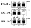
- an operating panel 72 is provided at a front upper portion of the support base 2, and as shown in FIG. 11, a push-button switch 73 for dehydration, a push-button switch 74 for deodorization, and a push-button switch 75 for filtration, are installed on the operating panel 72.
- the pushbutton switches 73-75 are connected to a controller 76.
- the numerals, 200, 201, and 202 denote "Dehydration,” “Deodorizing,” and “Filtration,” respectively.
- the controller 76 is adapted to control the operation of the air compressor 20 when the push-button switch 73 for dehydration is pushed ON, control the operation of the blower 53 when the push-button switch 74 for deodorizing is pushed ON, and further control the operations of the purified water recycle pump 24 and the grinding water supply pump 25 when the push-button switch 75 for filtration is pushed ON.
- the controller 76 controls the operation of the purified water recycle pump 24 so that purified water is fed to the nozzle 1a in accordance with a work signal provided from the lens grinding apparatus 1.
- a timer T (see FIG. 4) is mounted to the upper wall 40b of the body case 40 and control is made so that the time set by the timer T is a filtration time.
- the open/close operating lever 47b is operated to open the open-ing/closing valve 47, allowing the grinding water discharge hose 30 to communicate with the feed port 15.
- the open/close operating lever 45b is operated to open the opening/closing valve 50
- the open/close operating lever 90b is operated to open the opening/closing valve 90, allowing the purified water recycle hose 31 to communicate with the drain ports 16 and 1C.
- the open/close operating lever 49b is operated to close the opening/closing valve 49,' causing the communication between the air discharge side of the air compressor 20 and the feed port 15 to be cut off.
- a control panel (not shown) of the lens grinding apparatus 1 is operated to let the grinding wheel 1b rotate at high speed, thereby grinding the to-be-ground lens into the glasses lens shape (globe shape).
- the controller 76 upon receipt of a grinding start signal from the lens grinding apparatus 1, the controller 76 causes the purified water recycle pump 24 and the grinding water supply pump 25 to operate.
- the purified water present within the purified grinding water chamber 3a in the purified water tank 3 is pumped up by the purified water recycle pump 24 as indicated with arrow A1 in FIG. 9 (see FIG. 10) and is fed through the purified grinding water supply hose 26 to the nozzle 1a disposed within the lens grinding apparatus 1.
- the purified water is sprayed from the nozzle 1a toward the grinding section A including the grinding wheel 1b of the lens L to cool the grinding section A and wash away grinding wastes.
- the purified water after thus washing away of grinding wastes becomes discharged grinding water and is allowed to flow down together with the grinding wastes into the discharged grinding water chamber 3b in the grinding water tank 3 from the bottom of the lens grinding apparatus 1 through the grinding water discharge hose 19, as indicated with arrow A2 (see FIG. 10).
- the grinding water discharge pump 25 sucks the grinding water present within the discharged grinding water chamber 3b in the grinding water tank 3 together with grinding wastes and supplies the discharged grinding water containing the grinding wastes into the grinding wastes separating filter 10 through the grinding water discharge hose 30, opening/closing valve 47 and feed port 15, as indicated with arrow A3 (see FIG. 10).
- the discharged grinding water is filtered and separated from grinding wastes by means of the grinding wastes separating filter 10, then flows down to the bottom side of the separating vessel body 9.
- the discharged grinding water after separation from grinding wastes becomes purified water and is conducted to the connecting pipe 16b through the drain port 16, drain pipe 16c and opening/closing valve 50 and also through the drain port 16', drain pipe 16d, opening/closing valve 90, drain pipes 16e, 16c and opening/closing valve 50.
- the drain ports 16 and 16' are vertically offset from each other, the drainage efficiency is improved.
- the purified water conducted to the connecting pipe 16b is returned into the discharged grinding water chamber 3b in the grinding water tank 3 through the purified water recycle hose 31 as indicated with arrow A4 (see FIG. 10) and is sucked in and recycled by the purified water recycle pump 24.
- the push-button switch (button) 74 for deodorizing is pushed ON and this ON signal is inputted to the controller 76.
- the controller 76 Upon receipt of the ON signal by the push button switch 74 the controller 76 causes the blower 53 to operate and a negative suction pressure induced by the blower 53 is exerted on the interior of the upper space in the purified grinding water chamber 3a through the deodorizing device body 52, the air hoses 69 and 46a and is also exerted on the grinding chamber 1d through the grinding water discharge hose 19.
- the air which contains the offensive smell developed in the grinding chamber 1 and the offensive smell in the upper space of the purified grinding water chamber 3a is sucked into the deodorizing device body 52 through the air hoses 46a and 69, then passes through the filter 64 and the activated charcoal 63 and is thereafter discharged from the blower 53.
- foams and grinding wastes developed on the surface of purified water contained in the air are collected by the filter 64 and the offensive smell contained in the air which has passed through the filter 64 is adsorbed on the activated charcoal 63.
- only the air freed from the offensive smell is discharged to the atmosphere from the blower 53.
- the offensive smell developed in the grinding chamber 1d of the lens grinding apparatus 1 does not leak to the exterior and thus there is no fear of the worker being offended by the offensive smell.
- the state of the interior of the transparent air hose 69 can be visually checked through the transparent cover 71 applied to the window 70 which is formed in an upper wall 40d of the body case 40. Therefore, even if the foams formed on the surface of the purified water in the purified grinding water chamber 3a are sucked into the air hose 69 together with air, it is possible to check the state of the foams present within the air hose 69. Consequently, it is possible to easily determine the timing for the work of taking out the deodorizing device body 52 and replacing the filter 64 and the timing for the work of taking out the air hose 69 and washing the interior thereof, whereby it is possible to prevent a bad influence on the deodorization effect which occurs when the amount of sucked foams is large.
- the opening/closing valve 47 is opened by operating the open/close operating lever 47b, allowing the grinding water discharge hose 30 to communicate with the feed port 15.
- the opening/closing valves 50 and 90 are opened by operating the open/close operating levers 45b and 90b, respectively, allowing the purified water recycle hose 31 to communicate with the drain ports 16 and 16'.
- the opening/closing valve 49 is closed by operating the open/close operating lever 49b to cut off the communication between the air discharge side of the air compressor 20 and the feed port 15.
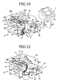
- the connecting pipe 31a of the purified water recycle hose 31 is removed from the connecting pipe 16b, the hose hook HF of the connecting pipe 16 is engaged in the hose hook hole 40c formed in the body case 40, and the grinding water storage vessel 8 is disposed under the connecting pipe 16b, as shown in FIG. 12.
- the grinding water discharge pump 25 sucks in the discharged grinding water from the interior of the discharged grinding water chamber 3b in the grinding water tank 3 together with grinding wastes and supplies the discharged grinding water containing the grinding wastes into the grinding wastes separating filter 10 through the grinding water discharge hose 30, opening/closing valve 47 and feed port 15 (see arrow A3 in FIG. 9).
- the discharged grinding water is filtered and separated from the grinding wastes by the grinding wastes separating filter 10 and flows down to the bottom side of the separating vessel body 9.
- the discharged grinding water separated in the separating vessel 9 becomes purified water and is conducted to the connecting pipe 16b through the drain port 16, drain pipe 16c and opening/closing valve 50 and also through the drain port 16', drain pipe 16d, opening/closing valve 90, drain pipes 16e, 16c and opening/closing valve 50.
- This purified water is then allowed to flow down from the connecting pipe 16b into the grinding water storage vessel 8 as indicated with arrow A5 in FIG. 12. In this way the purified water stored in the grinding water storage vessel 8 is drained to the sewer or the like.
- Such filtration is performed only during the time set by the timer T and upon lapse of the set time the controller 76 makes control to turn OFF the grinding water discharge pump 25 and also turn OFF the LED (not shown) installed within the push button of the push-button switch 75 as in FIG. 11(c).
- a drain hose (not shown) may be connected to the connecting pipe 16b to drain purified water directly to the sewer through the said drain hose.
- the grinding water discharge pump 25 When grinding wastes are collected to a certain extent in the grinding wastes separating filter 10 and the amount of discharged grinding water filtered by the filter 10 decreases, the grinding water discharge pump 25 is turned OFF.
- the opening/closing valve 47 is closed by operating the open/close operating lever 47b to cut off communication between the grinding water discharge hose 30 and the feed port 15.
- the opening/closing valves 50 and 90 are brought into an open condition to let the purified water recycle hose 31 communicate with the drain ports 16 and 16'.
- the opening/closing valve 49 is opened by operating the open/close operating lever 49b to provide communication between the air discharge side of the air compressor 20 and the feed port 15.
- the connecting pipe 31a of the purified water recycle hose 31 may be removed from the connecting pipe 16b and the grinding water storage vessel 8 may be disposed under the connecting pipe 16b, or a drain hose (not shown) connected to the sewer may be connected to the connecting pipe 16b.
- the purified water after separation in the separating vessel body 9 is conducted to the connecting pipe 16b through the drain port 16, drain pipe 16c and opening/closing valve 50 and also through the drain port 1G, drain pipe 16d, opening/closing valve 90, drain pipes 16e, 16c and opening/closing valve 50, then is drained from the connecting pipe 16b in the manner described above.
- This purified water is returned into the purified grinding water chamber 3a through the purified water recycle hose 31.
- the connecting pipe 31a of the purified water recycle hose 31 is removed from the connecting pipe 16b and the grinding water storage vessel 8 is disposed under the connecting pipe 16b, the purified water flows down from the connecting pipe 16b into the vessel 8.
- the purified water stored in the grinding water storage vessel 8 is discarded to the sewer or the like.
- a drain hose (not shown) connected to the sewer is connected to the connecting pipe 16b
- the purified water discharged from the connecting pipe 16b is drained directly to the sewer through the said drain hose.
- the lever 14 is operated to cancel the fixed state of the lid 11 to the separating vessel body 9 with fixing screws 13.
- the lid 11 is taken off from the separating vessel body 9, then the grinding wastes separating filter 10 is removed from the interior of the vessel body 9, and the grinding wastes present in the filter 10 is discarded. Thereafter, the grinding wastes separating filter 10 is returned to the separating vessel body 9 and the upper portion of the vessel body 9 is closed with the lid 11 by reversing the above operation, followed by execution of the foregoing "grinding work” and “grinding water treatment.” Such a grinding water treatment is repeated.
- the opening/closing valves 47, 48 and 50 described above may be constituted by solenoid valves so as to be switched over between their open and closed conditions automatically by the controller 76 at the time of performing the foregoing grinding work, filtration of the discharged grinding water, deodorization, and dehydration of grinding wastes by the air pump 20.
- the numeral 80 denotes a remote controller provided with the same push-button switches as the push-button switches (buttons) 73, 74 and 75 provided on the operating panel 72.
- opening/closing valves 47 and 49 this construction does not always constitute a limitation.
- this three-way change-over valve is constituted by an electromagnetic three-way change-over valve, its switching operation can be done automatically, whereby the operability thereof is improved. This is also the case with the other opening/closing valves described above.
- connecting pipe 16b and the purified water recycle hose 31 are coupled and uncoupled to return the grinding water after the grinding water treatment into the purified grinding water chamber 3a, allow it to flow down into the grinding water storage vessel 8, or drain it to the sewer, there is not always made limitation to this construction.
- a three-way change-over valve may be provided in the connecting pipe 16b to switch over between communication of the pipe 16b with the purified water recycle hose 31 and a pipe to the sewer and blocking of the communication.
- a three-way change-over valve may be provided in the connecting pipe 16b to switch over between communication of the pipe 16b with the purified water recycle hose 31 and a pipe to the grinding water storage vessel 8 side and blocking of the communication.
- each may be constituted by an electromagnetic three-way valve, whereby their switching operations can be done automatically. Further, for attaining a higher efficiency there may be provided a multi-way change-over valve or an electromagnetic change-over valve which makes communication between the connecting pipe 16b and one of the purified water recycle hose 31, a pipe to the sewer and a pipe to the grinding water storage vessel 8 side.
- the grinding water treating apparatus (27) is provided with the grinding water treating means (grinding water treating section 27a) which filters grinding water (discharged grinding water) after used in the glasses lens grinding work to separate grinding wastes and produce purified water and the deodorizing means (deodorizing device 51) for removing an offensive smell developed in the grinding water treating means (27a) and an offensive smell in the grinding water storage vessel (grinding water tank 3), the grinding water treating means (27a) and the deodorizing means (51) being disposed within the same housing (body case 40).
- the grinding water treating means grinding water treating section 27a
- filters grinding water discharged grinding water after used in the glasses lens grinding work to separate grinding wastes and produce purified water
- the deodorizing means deodorizing device 51 for removing an offensive smell developed in the grinding water treating means (27a) and an offensive smell in the grinding water storage vessel (grinding water tank 3)
- the grinding water treating means (27a) and the deodorizing means (51) being disposed within the same housing (body case 40).
- the grinding water treating apparatus (27) having the grinding water treating means (27a) and the deodorizing means (52) can be accommodated in a limited receptacle space and thus it is possible to attain the reduction of the receptacle space.
- the grinding water treating means (27a) has a one-pass treating means (the grinding wastes separating filter 10) which causes grinding water to pass once therethrough to filter off grinding wastes.
- grinding water (purified water) after filtration does not return to the grinding water storage vessel (grinding water chamber 3a), but filtered water high in clarity can be drained directly to the sewer.
- the one-pass treating means (10) has the pressurizing means (air compressor 20) which applies a predetermined pressure to the grinding water treating means (27a) to squeeze out and filter grinding water from grinding wastes in the grinding water treating means, thereby permitting the grinding wastes to be treated at a time.
- the grinding water present within the one-pass treating means (10) can be separated from grinding wastes quickly, easily and positively and thus it is possible to facilitate the discard of only the grinding wastes.
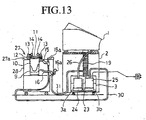
- a third embodiment of the present invention will be described below. As to the same constructions and functions as in the first and second embodiments, explanations thereof will be omitted.
- an injection nozzle N as injection means which radially injects purified water flowing out from the drain port 16, using a known means, is attached to the tip of the purified water recycle hose 31.
- the tip of the purified water recycl e hose 31 is positioned near a discharge port 19a of a grinding water discharge hose 19. In this case, the closer to the discharge port 19a of the grinding water discharge hose 19 the tip of the purified water recycle hose 31 is, the better.
- purified water resulting from separation of grinding wastes by a grinding wastes separating filter 10 is returned into the discharged grinding water chamber 3b in the grinding water tank 3 through the purified water recycle hose 31.
- this purified water is injected into the discharged grinding water chamber 3b through the injection nozzle N which is positioned above the chamber 3b.
- the tip of the purified water recycle hose 31 with the injection nozzle N attached thereto is positioned near the discharge port 19a of the grinding water discharge hose 19, the purified water injected from the nozzle N blends with discharged grinding water flowing down from the grinding water discharge hose 19 after use in the grinding work and at the same time can cover the portion where the discharged grinding water which is flowing down and the discharged grinding water which has already been stored in the chamber 3b strike against each other.
- the injection nozzle N attached to the opposite end of the purified water recycle hose 31 can inject purified water radially, it is possible to inject (spray) the purified water so as to cover substantially the whole surface of the discharged grinding water stored in the grinding water tank 3.
- a divergence angle ⁇ (see FIG. 17) of purified water injected by the injection nozzle N is in the range of 120° to 180°.
- the divergence angle ⁇ can be adjusted to an arbitrary angle.
- the discharged grinding water chamber 3b to which purified water is returned and the purified grinding water chamber 3a adjacent thereto are in communication with each other through a partition filter 23. Therefore, the grinding water (purified water) after separation from grinding wastes by the partition filter 23 flows into the purified grinding water chamber 3a and is sucked in and circulated by means of a purified water recycle pump 24.
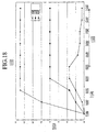
- Evaluation items are the height of foam layer, i.e., the height of foams (cm), from the surface of grinding water relative to the time elapsed after filtration.
- the evaluation was made in the following manner. Thirty plastic lenses (CR-39) apt to produce a lot of foams were subjected to grinding continuously under constant filtration. The height of foams was measured at every ten lenses, and after grinding the thirty lenses, only filtration was conducted for 10 minutes continuously and the height of foams was measured in the same way.
- the numeral 100 stands for “Item”
- numeral 101 stands for “foam height (cm)
- numeral 102 stands for “with injection nozzle”
- numeral 103 stands for “without injection nozzle”
- numeral 104 stands for “without filter”
- numeral 105 stands for “0 lens”
- numeral 106 stands for “10 lenses”
- numeral 107 stands for “20 lenses”
- numeral 108 stands for “30 lenses”
- numeral 109 stands for "0 minute after filtration”
- numeral 110 stands for "1 minute after filtration”
- numeral 111 stands for "3 minutes after filtration.”
- numeral 112 stands for "change in foam height for each number of lens”
- numeral 113 stands for “foam height (cm)
- numeral 114 stands for "number of lens under filtration”
- numeral 115 stands for "time of only filtration continued”
- numeral 116 stands for "with nozzle”
- numeral 117 stands for “without nozzle”
- numeral 118 stands for "FS not used”
- numeral 119 stands for "0 lens”
- numeral 120 stands for “10 lenses”
- numeral 121 stands for “20 lenses”
- numeral 122 stands for “30 lenses”
- numeral 123 stands for "0 minute”
- numeral 124 stands for "1 minute”
- numeral 125 stands for “3 minutes”
- numeral 126 stands for "5 minutes”
- numeral 127 stands for “7 minutes”
- numeral 128 stands for "10 minutes.”
- the grinding water treating means 27a is provided with the purified water recycle hose 31 for returning purified water to the grinding water storage vessel 3, and the injection means (injection nozzle N) for injecting purified water to blend it with grinding water flowing into the grinding water storage vessel (grinding water tank 3) is attached to the tip of the purified water recycle hose 31, thereby extinguishing foams produced on the surface of the grinding water stored in the vessel 3.
- the grinding water treating means 27a is provided with the purified water recycle hose 31 for returning purified water to the grinding water storage vessel 3, and the injection means (injection nozzle) is attached to the tip of the purified water recycle hose 31 which injection means injects purified water radially to cover the surface of the grinding water already stored within the grinding water storage vessel 3, thereby extinguishing the foams formed on the surface of the grinding water stored in the vessel 3.
- the portion where the grinding water flowing into the grinding water storage vessel 3 strikes against the grinding water already stored in the grinding water storage vessel 3 is covered with purified water injected from the purified water recycle hose 31.
- the lens grinding apparatus 1' is provided with a grinding apparatus body (not shown), a grinding water tank (grinding water storage vessel) 3 which stores discharged grinding water after use in a glass lens grinding work in the grinding apparatus body, and a grinding water supply hose (grinding water discharge hose) 19 for admitting the discharged grinding water into the grinding water tank 3.
- a grinding apparatus body not shown
- a grinding water tank grinding water storage vessel
- grinding water supply hose grinding water discharge hose
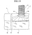
- An injection nozzle N as injection means is attached to a tip 19a of the grinding water discharge hose 19 to inject the discharged grinding water radially.
- the surface of discharged grinding water pre-stored in a discharged grinding water chamber 3b of the grinding water tank 3 can be covered with the discharged grinding water which is injected through the injection nozzle N, and thus foams produced on the surface of the discharged grinding water can be extinguished.
- a divergence angle ⁇ of the discharged grinding water injected by the injection nozzle N is in the range of 120° to 180°.
- the divergence angle ⁇ can be adjusted to an arbitrary value.
- the lens grinding apparatus 1' of this fourth embodiment is provided with the grinding water storage vessel (grinding water tank 3) for the storage of grinding water (discharged grinding water) after use in the glasses lens grinding work and the grinding water supply hose (grinding water discharge hose 19) for admitting grinding water into the grinding water storage vessel 3, further, the injection means (injection nozzle N) is attached to the tip 19a of the grinding water supply hose 19 to inject grinding water radially, thereby covering the surface of the grinding water already stored in the grinding water storage vessel 3 and extinguishing foams produced on the surface of the grinding water.
- the grinding water storage vessel grinding water tank 3
- the grinding water supply hose grinding water discharge hose 19
Landscapes
- Engineering & Computer Science (AREA)
- Mechanical Engineering (AREA)
- Chemical & Material Sciences (AREA)
- Ceramic Engineering (AREA)
- Inorganic Chemistry (AREA)
- Grinding-Machine Dressing And Accessory Apparatuses (AREA)
- Grinding And Polishing Of Tertiary Curved Surfaces And Surfaces With Complex Shapes (AREA)
Abstract
Description
- The present invention relates to a lens grinding apparatus having a grinding water storage vessel.
- In a conventional apparatus for treatment of grinding water for use in a lens grinding apparatus, (hereinafter referred to as "grinding water treating apparatus"), a grinding water treating means which filters grinding water after used in a glasses lens grinding work to separate grinding wastes and produce purified water and a deodorizing means for removing an offensive smell developed in the grinding water treating means and also developed in a grinding water storage vessel, are disposed within different housings respectively.
- A housing which contains therein the grinding water treating means, a housing which houses therein the deodorizing means, as well as a space present above the grinding water storage vessel and a housing with the deodorizing means disposed therein, are interconnected through hoses or pipes. In this case, an offensive smell is removed through hoses or the like which connect the housings.
- In the above grinding water treating apparatus, since the grinding water treating means and the deodorizing means are disposed in different housings, the size of the grinding water treating apparatus becomes large, thus giving rise to the problem that it is difficult to accommodate the apparatus within a limited receptacle space.
- On the other hand, when the grinding water flowing into the grinding water storage vessel mixes into the grinding water already stored in the grinding water storage vessel, there sometimes occurs a case where foams are formed.
- To extinguish foams developed on the surface of the grinding water stored in the grinding water storage vessel, there are known a lens grinding apparatus having a defoaming device which injects grinding water containing a defoaming agent toward the foams in the form of spray (shower) to remove the foams, a lens grinding apparatus having a defoaming device which injects pressurized grinding water upward from below the level of already-stored grinding water with use of an injection nozzle connected to the grinding water storage vessel, a lens grinding apparatus having a foam suction means which sucks the foams developed on the surface of grinding water, and a lens grinding apparatus wherein a foam overflow path for overflowing the foams developed on the grinding water surface is provided in the grinding water storage vessel.
- However, there sometimes has occurred a case where grinding wastes contained in grinding water which has been used in grinding a glasses lens adhere to the foams developed and harden in the form of cluster.
- Consequently, it is difficult to crush or suck the foams once clustered or cause them to flow out, with consequent occurrence of the problem that the foams cannot be extinguished to a satisfactory extent.
- The present invention has been accomplished in view of the above mentioned problems in the conventional apparatuses and it is an object of the present invention to provide a lens grinding apparatus capable of suppressing the formation of foams when grinding water flowing into a grinding water storage vessel mixes into grinding water already stored in the vessel.
- According to the present invention, for achieving the foregoing object, there is provided a lens grinding apparatus comprising a grinding water storage vessel for the storage of grinding water which has been used in grinding a glasses lens and a grinding water supply hose for allowing the grinding water to flow into the grinding water storage vessel, wherein an injection means is provided at a tip portion of the grinding water supply hose to inject the grinding water radially, thereby allowing the grinding water to cover the surface of the grinding water already stored in the grinding water storage vessel and extinguishing foams formed on the .surface of the grinding water.
-
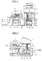
- FIG. 1
- is an explanatory piping diagram showing schematically a lens grinding apparatus and a grinding water treating apparatus according to a first embodiment of the present invention;
- FIG. 2
- is an explanatory piping diagram showing schematically a lens grinding apparatus and a grinding water treating apparatus according to a second embodiment of the present invention;
- FIG. 3
- is an explanatory diagram (a left-hand side view of a support base shown in FIG. 2) showing an example of utilization of the support base illustrated in FIG. 2;
- FIG. 4
- is a schematic explanatory diagram showing a lens grinding apparatus and a grinding water treating apparatus according to a modification of the second embodiment of the present invention;
- FIG. 5
- is an explanatory piping diagram of the grinding water treating apparatus shown in FIG. 4;
- FIG. 6
- is an exploded perspective view of a deodorizing device shown in FIG. 4;
- FIG. 7
- is a diagram explanatory of operation of the deodorizing device shown in FIG. 6;
- FIG. 8(a)
- is a sectional view of a screw inserting cylinder portion in a deodorizing case;
- FIG. 8(b)
- is a sectional view of a partition wall portion in the deodorizing case;
- FIG. 8(c)
- is a sectional view taken along line B-B in FIG. 8(b);
- FIG. 8(d)
- is. a sectional view taken along line C-C in FIG. 8(b);
- FIG. 9
- is an explanatory piping diagram of components of the lens grinding apparatus shown in FIG. 4;
- FIG. 10
- is an explanatory diagram showing the flow of grinding water;
- FIGS. 11(a) to 11(d)
- are explanatory diagrams of an operating panel shown in FIG. 4;
- FIG. 12
- is a diagram explanatory of a grinding water non-recycle treatment in the grinding water treating apparatus shown in FIG. 4;
- FIG. 13
- is an explanatory piping diagram showing schematically a lens grinding apparatus and a grinding water treating apparatus according to a third embodiment of the present invention;
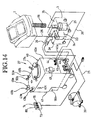
- FIG. 14
- is an explanatory piping diagram of the grinding water treating apparatus shown in FIG. 13;
- FIG. 15
- is an explanatory piping diagram of components of the lens grinding apparatus shown in FIG. 13;
- FIG. 16
- is an explanatory diagram showing the flow of grinding water;
- FIG. 17
- is an enlarged explanatory diagram of portion D shown in FIG. 15;
- Fig. 18
- is a graph showing results of valuation of the grinding water treating apparatus according to the third embodiment; and
- FIG. 19
- is an enlarged explanatory diagram of a lens grinding apparatus according to a fourth embodiment of the present invention.
- Some preferred embodiments of the present invention will be described in detail with reference to the accompanying drawings hereinafter.
- A first embodiment of the present invention will be described below.
- In FIG. 1,
reference numeral 1 denotes a lens grinding apparatus,numeral 2 denotes an apparatus support base for supporting the lens grinding apparatus, and numeral 3 denotes a grinding water tank (grinding water storage vessel) disposed under theapparatus support base 2. A grindingwater supply pump 4 is installed in the interior of the grindingwater tank 3. Numerals 4a and 4b denote a suction port and a discharge port, respectively, of the grindingwater supply pump 4. One port 5a of a three-way change-over valve 5 is connected to thedischarge port 4b of the grindingwater supply pump 4. - Numerals 5b and 5c denote the other two ports of the three-way change-over valve 5 and numeral 5d denotes a change-over lever in the three-way change-over valve 5. By switching the change-over
lever 5d in the three-way change-over valve 5 to theport 5b side, theports 5a and 5b come into communication with each other and at the same time the communications between theports 5a, 5b and theport 5c are cut off. Further, by switching the change-overlever 5d in the three-way changeover valve 5 to theport 5c side, theports 5a and 5c come into communication with each other and at the same time the communications between theports 5a, 5c and theport 5b are cut off. - A
support base 6 as a housing is disposed sideways of theapparatus support base 2. On thesupport base 6 is mounted a grindingwater treating apparatus 7, while under thesupport base 6 is disposed a grinding water storage vessel 8 (e.g., a bucket). - The grinding
water treating apparatus 7 is provided with a grinding water treating means and a deodorizing means. - A grinding water treating section (grinding water treating means) 7a has a bottomed, cylindrical, transparent (or translucent) separating vessel body (pressure-resistant vessel) 9, a bottomed, cylindrical, transparent (or translucent) grinding wastes separating filter 10 (one-pass treating means) disposed within the separating
vessel body 9, alid 11 which closes an upper-end opening of the separatingvessel body 9, a packing 12 interposed between thelid 11 and the separatingvessel body 9, fixingscrews 13 which fix thelid 11 to the separatingvessel body 9, and alever 14 for performing the fixing operation of the fixing screws 13 and for cancelling the same operation. - The grinding
water treating section 7a is further provided with afeed port 15 connected to the upper end portion of the separatingvessel body 9, adrain port 16 formed in a bottom of the separatingvessel body 9, and a three-way change-overvalve 17 oneport 17a of which is connected to thefeed port 15. -
Numerals valve 17, and numeral 17d denotes a change-over lever in the three-way change-overvalve 17. - In the three-way change-over
valve 17, by switching thechangeover lever 17d to theport 17b side theports ports port 17c are cut off. Further, by switching the change-overlever 17d in the three-way change-overvalve 17 to theport 17c side theports ports port 17b are cut off. - A grinding water supply nozzle (not shown), which is disposed within the
lens grinding apparatus 1, is connected to theport 5b of the three-way change-over valve 5 through a grindingwater supply hose 18. In thelens grinding apparatus 1, a grinding wheel (not shown) is rotated at high speed to grind a lens to be ground (unground circular glasses lens) into a glasses lens shape (globe shape). - For the grinding work, the grinding water stored in the grinding
water tank 3 is pumped up by the grindingwater supply pump 4 and is fed to the nozzle (not shown) in thelens grinding apparatus 1 through both three-way change-over valve 5 and grindingwater supply hose 18, then is, fed from the nozzle to a lens grinding section using the grinding wheel to cool the grinding section and wash away grinding wastes. For this grinding work there is used a known construction, so the details thereof will here be omitted. - The grinding water which has thus washed away the grinding wastes is allowed to flow down together with the grinding wastes through a bottom of the
lens grinding apparatus 1 and further through adrain hose 19 into the grindingwater tank 3. - Further, an air compressor (a pressurizing means, a compressed air supply means, i.e., a compressed gas supply means) 20 is connected to the
port 17b of the three-way change-overvalve 17 through anair hose 21, and theport 5c of the three-way change-over valve 5 and theport 17c of the three-way change-overvalve 17 are connected together through a grindingwater supply hose 22. The grindingwater supply hose 22 is attached to theport 17c removably. - The deodorizing means is a deodorizing device (not shown) disposed in a space formed, for example, under the grinding
water treating section 7a and inside thesupport base 6. - The following description is now provided about the
lens grinding apparatus 1 and the grindingwater treating apparatus 7 both constructed as above. - In the above construction, first the change-over
lever 5d of the three-way change-over valve 5 is switched to theport 5b side, allowing theports 5a and 5b to come into communication with each other and blocking the communication between theports 5a, 5b and theport 5c. In this state, the grinding wheel (not shown) in thelens grinding apparatus 1 is rotated at high speed to grind the to-be-ground lens into a glasses lens shape (globe shape). - At this time, the grinding water stored in the grinding
water tank 3 is pumped up by the grindingwater supply pump 4 and is fed to the nozzle (not shown) in thelens grinding apparatus 1 through the three-way change-over valve 5 and the grindingwater supply hose 18, then is fed from the nozzle to the lens grinding section using the grinding wheel to cool the grinding section and wash away grinding wastes. The grinding water which has thus washed away the grinding wastes is allowed to flow down together with the grinding wastes from the bottom of thelens grinding apparatus 1 to the grindingwater tank 3 through thedrain hose 19. - When the grinding water stored in the grinding
water tank 3 becomes somewhat turbid due to the grinding wastes in the lens grinding work by thelens grinding apparatus 1, the work is stopped. Then, the change-overlever 5d of the three-way change-over valve 5 is switched to theport 5c side to establish communication between theports 5a and 5c. Further, the change-overlever 17d of the three-way change-overvalve 17 is switched to theport 17c side to establish communication between theports - In this state, the grinding
water supply pump 4 is activated to supply the grinding water stored in the grindingwater tank 3, together with grinding wastes, into the grindingwastes separating filter 10 in the grindingwater treating apparatus 7 through the three-way change-over valve 5, grindingwater supply hose 22 and three-way change-overvalve 17. As a result, the grinding water passes through the grindingwastes separating filter 10, flows down from thedrain port 16 and is stored in the grindingwater storage vessel 8. At this time, the grinding wastes contained in the grinding water are collected by the grindingwastes separating filter 10. - When the grinding wastes are collected to a certain extent within the grinding
wastes separating filter 10 and the amount of grinding water flowing down into the grindingwater storage vessel 8 decreases, thefilter 10 is clogged and hence the grinding water in the filter is difficult to flow. - As the degree of clogging of the grinding
wastes separating filter 10 becomes higher, the internal pressure of thefilter 10 tends to become higher due to the grinding water supplied. In this connection there may be adopted a construction wherein an intra-vessel sensor (not shown) is disposed in an upper portion (e.g., on a lower surface of the lid 11) within the separatingvessel body 9 to detect a clogged state of the grindingwastes separating filter 10, and when the internal pressure of thefilter 10 has become higher than a predetermined value, this state is displayed for example by an LED (not shown) on the basis of a pressure detection signal provided from the intra-vessel pressure sensor (not shown) to let a worker know this state. - In this case, therefore, after the operation of the grinding water supply pump 5 is stopped, the change-over
lever 17d of the three-way change-overvalve 17 is switched to theport 17b side to establish communication between theports ports port 17c. Thereafter, theair compressor 20 is turned ON to supply compressed air to above the grindingwastes separating filter 10 through theair hose 21 and the three-way change-overvalve 17. As a result, under the action of the air pressure, grinding water which has been staying on an upper portion of the grinding wastes in the grindingwastes separating filter 10 passes through the grinding wastes thefilter 10 and flows down into the grindingwater storage vessel 8 through thedrain port 16. - When there is little grinding water flowing down from the
drain port 16, theair compressor 20 is turned OFF and the fixed state of thelid 11 to the separatingvessel body 9 by the fixing screws 13 is cancelled by operating thelever 14. Thereafter, thelid 11 is removed from the separatingvessel body 9, the grindingwastes separating filter 10 is taken out from the interior of the separating vessel body, and the grinding wastes present within thefilter 10 are discarded. - When the degree of turbidity is low, the grinding water present in the grinding
water storage vessel 8 is returned to the grindingwater tank 3 for use in the grinding work, while when the degree of turbidity is high, the grinding water is discarded by flowing it to sewage for example. - Turbid grinding water and grinding wastes present in the grinding
water tank 3 are treated by repeating such a process. - Although in the above embodiment the ports of the three-way change-over
valves 5 and 17 are switched from one to another bymanual operating levers - For example, there may be adopted a construction wherein a turbidity sensor for detecting the state of turbidity in the interior of the grinding
water tank 3 is provided, and when a somewhat progressed state of turbidity is detected by the turbidity sensor, the state of connection of each port in the three-way change-overvalve 5 and 17 is switched over automatically in the same way as above and there is performed the grinding wastes separating work by the grindingwater treating apparatus 7. - Or there may be adopted a construction wherein the grinding wastes separating work involving such switching of the connection condition among the ports of the three-way change-over
valves 5 and 17 is done automatically at every predetermined grinding time. - As described above, the grinding water treating apparatus (7) according to this first embodiment is provided with the grinding water treating means (grinding
water treating section 7a) which filters grinding water having been used in the lens grinding work to separate grinding wastes and produce purified water and the deodorizing means (deodorizing device (not shown)) for removing an offensive smell present in the interior of the grinding water treating means (7a) and the grinding water storage vessel (storage tank 3), the grinding water treating means (7a) and the deodorizing means (not shown) being disposed within the same housing (support base 6). - With this construction, the grinding water treating apparatus (7) provided with both grinding water treating means (7a) and deodorizing means (not shown) can be accommodated within a limited receptacle space and hence it is possible to reduce the receptacle space.
- In the grinding water treating apparatus, (7) according to this first embodiment, the grinding water treating means (7a) has a one-pass treating means (the grinding wastes separating filter 10) for passing grinding water once therethrough to filter off grinding wastes.
- According to this construction, grinding water (purified water) after the filtration does not return to the grinding water storage vessel (3), but filtered water high in clarity can be drained directly to the sewerage.
- Further, in the grinding water treating apparatus (7) according to this first embodiment, the one-pass treating means (10) has a pressurizing means (the air compressor 20) which applies a predetermined pressure to the grinding water treating means (7a) to squeeze out and filter grinding water from grinding wastes present within the grinding water treating means (7a), thereby permitting the grinding wastes to be treated at a time.
- According to this construction, even if the one-pass treating means (10) is clogged, the grinding water present therein can be separated from the grinding wastes quickly, easily and positively, permitting easy discard of only the grinding wastes.
- A second embodiment of the present invention will be described below.
- In FIG. 2, the
numeral 1 denotes a lens grinding apparatus,numeral 2 denotes an apparatus support base for supporting thelens grinding apparatus 1, and numeral 3 denotes a grinding water tank (grinding water storage vessel) disposed under theapparatus support base 2. With apartition filter 23, the interior of the grindingwater tank 3 is partitioned into a purified grinding water chamber (purified water chamber) 3a and a discharged grinding water chamber (waste water chamber) 3b. - In the purified grinding
water chamber 3a is disposed a purifiedwater recycle pump 24, while in the discharged grindingwater chamber 3b is disposed a discharged grindingwater pump 25. A discharge side of the purifiedwater recycle pump 24 and a grinding water supply nozzle (not shown) disposed within thelens grinding apparatus 1 are connected together through a purified grindingwater supply hose 26. - In the
lens grinding apparatus 1, a grinding wheel (not shown) is rotated at high speed to grind a lens to be ground (unground circular glasses lens) into a glasses lens shape (globe shape). - In this grinding work, purified water present within the purified grinding
water chamber 3a is pumped up by the purifiedwater recycle pump 24 and is fed through the purified grindingwater supply hose 26 to the nozzle (not shown) disposed within thelens grinding apparatus 1, then is fed from this nozzle to a lens grinding section using the grinding wheel to cool the grinding section and wash away grinding wastes. As a construction for such a grinding work there is used a known one, so a detailed description thereof will here be omitted. - Grinding water ("discharged grinding water" hereinafter) after thus washing away of grinding wastes is allowed to flow down together with the grinding wastes into the discharged grinding
water chamber 3b in the grindingwater tank 3 from a bottom of thelens grinding apparatus 1 through a grinding water discharge hose (grinding water supply hose) 19. - Sideways of the
apparatus support base 2 is disposed a grindingwater treating apparatus 27 which is installed. on a support base (housing) 28 with caster. As will be described later, the grindingwater treating apparatus 27 is provided with a grinding water treating means which filters discharged grinding water to separate grinding wastes and produce purified grinding water ("purified water" hereinafter) and a deodorizing means for removing an offensive smell developed within the grinding water treating means, etc. - A grinding water treating section (grinding water treating means) 27a has a bottomed cylindrical separating vessel body (pressure-resistant vessel) 9 and a bottomed cylindrical grinding wastes separating filter (one-pass means) 10 disposed within the separating
vessel body 9. The grindingwater treating section 27a is also provided with alid 11 which closes an upper-end opening of the separatingvessel body 9, a packing 12 interposed between thelid 11 and the upper end of the separatingvessel body 9, fixingscrews 13 which fix thelid 11 to the separatingvessel body 9, and alever 14 for performing the fixing operation of the fixing screws 13 and cancelling the same operation. - The grinding
water treating section 27a is further provided with afeed port 15 connected to the upper end portion of the separatingvessel body 9 and adrain port 16 provided in a lower portion of the separatingvessel body 9. - An opening/closing valve (not shown) is provided in each of the
feed port 15 and drainport 16. Numerals 15a and 16a denote open/close operating lever for the opening/closing valve (not shown) in thefeed port 15 and drainport 16. - One end of a grinding
water discharge hose 30 is connected to a discharge port (not shown) of the grindingwater discharge pump 25, while an opposite end of the grindingwater discharge hose 30 is connected to thefeed port 15 removably with use of a connector or a screw. - On the other hand, one end of a purified water recycle
hose 31 is connected to thedrain port 16 removably with use of a connector or a screw and an opposite end thereof is held in an upper portion of the purified grindingwater chamber 3a in the grindingwater tank 3 removably with use of a connector or a screw. As fixing means for the connector or screw there may be used a known connector or nut used for the connection of hose. - Further, the deodorizing means has a deodorizing device 32 (see FIG. 3) disposed under the separating
vessel body 9. - Next, a description will be given below of the operation of the lens grinding apparatus I and the grinding
water treating apparatus 27 both constructed as above. - In the above construction, the opening/closing valves (not shown) disposed in the
feed port 15 and thedrain port 16 are opened by operating the open/close operating levers lens grinding apparatus 1 is rotated at high speed to grind a to-be-ground lens into a glasses lens shape (globe shape). - At this time, purified water present within the purified grinding
water chamber 3a in the purifiedwater tank 3 is pumped up by the purifiedwater recycle pump 24 and is fed through the purified grindingwater supply hose 26 to the nozzle (not shown) disposed within thelens grinding apparatus 1, then is fed from the nozzle to the lens grinding section using the grinding wheel to cool the grinding section and wash away grinding wastes. - The purified water after thus washing away of grinding wastes becomes discharged grinding water and is allowed to flow down together with the grinding wastes from the bottom of the
lens grinding apparatus 1 into the discharged grindingwater chamber 3b in the grindingwater tank 3 through the grindingwater discharge hose 19. - In such a grinding work, the grinding
water discharge pump 25 sucks the discharged grinding water from the interior of the discharged grindingwater chamber 3b in the grindingwater tank 3 together with grinding wastes and supplies the discharged grinding water containing the grinding wastes into the grindingwastes separating filter 10 through the grindingwater discharge hose 30 and thefeed port 15. A single pump may be used in common to both purifiedwater recycle pump 24 and grindingwater discharge pump 25. - The discharged grinding water is separated from the grinding wastes by the grinding
wastes separating filter 10 and becomes purified water, which is returned into the purified grindingwater chamber 3a in the grindingwater tank 3 through thedrain port 16 and the purified water recyclehose 31. At this time, the grindingwastes separating filter 10 collects the grinding wastes contained in the discharged grinding water. - When the grinding wastes are collected to a certain extent by the grinding
wastes separating filter 10 and the amount of the discharged grinding water filtered by the grindingwastes separating filter 10 decreases, the purifiedwater recycle pump 24 and the grindingwater discharge pump 25 are turned OFF and thereafter thelever 14 is operated to cancel the fixed state of thelid 11 to the separatingvessel body 9 by the fixing screws 13. - Subsequently, the
lid 11 is removed from the separatingvessel body 9, the grindingwastes separating filter 10 is taken out from the interior of the separatingvessel body 9, and the grinding wastes collected in thefilter 10 are discarded. Then, thefilter 10 is returned to the separatingvessel body 9 and thevessel body 9 is closed with thelid 11 by reversing the above operation, thereafter, the foregoing "grinding work" and "grinding water treatmen" are allowed to proceed. Subsequently, such a grinding water-grinding wastes separating work is performed repeatedly. - In such a grinding water treatment, if the discharged grinding water filtering capacity of the grinding
wastes separating filter 10 is deteriorated, the grinding wastes collected by the grindingwastes separating filter 10 may be discarded as described above after squeezing out purified water from the grinding wastes by the air compressor (pressurizing means) (not shown) and subsequent drainage thereof from thedrain port 16. - If the purified water is somewhat turbid even after the application of such a grinding water treatment, there may be adopted a method involving removing the purified water recycle
hose 31 from the grindingwater tank 3, connecting thehose 31 to a sewer (not shown), and carrying out the foregoing grinding water treatment, whereby purified water free of grinding wastes can be discarded to the sewer. Alternatively, there may be adopted a method wherein the purified water recyclehose 31 is disconnected from thedrain port 16, while a drain hose (not shown) connected to the sewer is attached to thedrain port 16, and the foregoing grinding water treatment is carried out, thereby allowing turbid purified water free of grinding wastes to be discharged to the sewer. - By allowing such a recycle type grinding water treatment to be carried out by the grinding
water treating section 27a, there is formed a space under thesupport base 28 and therefore such a deodorizing device (deodorizing means) 32 as shown in FIG. 3 is disposed in the said space. - With the
deodorizing device 32, it is possible to remove an offensive smell (e.g., an offensive smell developed when grinding a plastic lens) developed within thelens grinding apparatus 1 and the grindingwater tank 3. - As described above, the grinding water treating apparatus (27) according to this second embodiment is provided with the grinding water treating means (grinding
water treating section 27a) which filters grinding water after used in grinding a glasses lens to separate grinding wastes and produce purified water and the deodorizing means (deodorizing device 32) for removing an offensive smell developed in both grinding water treating means (27a) and grinding water storage vessel (storage tank 3), the grinding water treating means (27a) and the deodorizing means (32) being disposed within the same housing (support base 28). - According to this construction, the grinding water treating apparatus (27) provided with both grinding water treating means (27a) and deodorizing means (not shown) can be accommodated within a limited receptacle space, thus permitting reduction of the receptacle space.
- In the grinding water treating apparatus (27) according to this second embodiment, the grinding water treating means (27a) has the one-pass treating means (grinding wastes separating filter 10) which causes grinding water to pass once therethrough to filter off grinding wastes.
- According to this construction, grinding water (purified water) after the filtration does not return to the grinding water storage vessel (3), but filtered water high in clarity can be discharged as it is to the sewer.
- A modification of the above second embodiment will be described below with reference to FIGS. 4 to 13, in which the same portions as in the second embodiment are identified by the same reference numerals as in the second embodiment.
- In FIG. 4,
numeral 1 denotes a lens grinding apparatus,numeral 2 denotes a rack-like apparatus support base which supports thelens grinding apparatus 1, and numeral 3 denotes a grinding water tank (grinding water storage vessel) disposed under theapparatus support base 2. - As shown in FIGS. 5 and 9, the interior of the grinding
water tank 3 is partitioned to a purified grinding water chamber (purified water chamber) 3a and a discharged grinding water chamber (waste water chamber) 3b by means of apartition filter 23. - As the
partition filter 23 is used a 100µ filter lest grinding dust should enter a deodorizing device (to prevent the passage of grinding wastes). Through this filter the purified grindingwater chamber 3a and the discharged grindingwater chamber 3b are in communication with each other while preventing the passage of grinding wastes, and the quantities of water stored in the two are almost equal to each other. - A purified
water recycle pump 24 is disposed in the purified grindingwater chamber 3a, while a grindingwater discharge pump 25 is disposed in the discharged grindingwater chamber 3b. A discharge side of the purifiedwater recycle pump 24 and a grindingwater supply nozzle 1a disposed in thelens grinding apparatus 1 are connected with each other through a purified grindingwater supply hose 26 as shown in FIG. 8. - One end of a grinding
water discharge hose 30 is connected to a discharge port (discharge side) of the grindingwater discharge pump 25, and a connectingpipe 30a is attached to an opposite end of the grindingwater discharge hose 30. - One end of a purified water recycle
hose 31 is put in communication with the purified grindingwater chamber 3a, and a connectingpipe 31a is attached to an opposite end of the purified water recyclehose 31. - In the
lens grinding apparatus 1, as shown in FIG. 9, agrinding wheel 1b is rotated at high speed to grind a lens to be ground (unground circular glasses lens) L into a glasses lens shape (globe shape). - In the grinding work, purified water present in the purified grinding
water chamber 3a is pumped up by the purifiedwater recycle pump 24 and is fed through the purified grindingwater supply hose 26 to anozzle 1a disposed within thelens grinding apparatus 1, then is fed from thenozzle 1a to a grinding section A which is for grinding the lens L with thegrinding wheel 1b, to cool the grinding section A and wash away grinding wastes (see FIG. 9). For such a grinding work there is used a known construction, so a detailed explanation thereof will here be omitted. - Purified water after thus washing away of grinding wastes becomes discharged grinding water, which is allowed to flow down together with grinding wastes from a bottom of the
lens grinding apparatus 1 into the discharged grindingwater chamber 3b in the grindingwater tank 3 through the grindingwater discharge hose 19. - Further, sideways of the
apparatus support base 2 is disposed abody case 40 with caster as a housing corresponding to thesupport base 28 shown in FIG. 2, and a grindingwater treating apparatus 27 is disposed within the body case 40 (see FIG. 4). The grindingwater treating apparatus 27 is provided with a grinding water treating means and a deodorizing means. - At a front upper portion of the
body case 40 is formed a frontupper projection 41 which projects to the front side, while in a front lower portion of thebody case 40 is formed afront opening 42 as shown in FIGS. 4 and 6, which is closed with afront lid 43 as in FIG. 4. - A grinding water treating section (grinding water treating means) 27a has a bottomed, cylindrical, separating vessel body (pressure-resistant vessel) 9 embedded in an upper portion of the
body case 40 and a bottomed, cylindrical, grinding wastes separating filter 10 (one-pass means) disposed within the separatingvessel body 9. - As shown in FIG. 4, an upper-end opening of the separating
vessel body 9 is closed with alid 11, and a packing 12 is interposed between thelid 11 and the upper end of the separatingvessel body 9 to ensure the interior of the vessel body in a hermetically sealed state. Thelid 11 is fixed to the separatingvessel body 9 with fixing screws 13.Numeral 14 denotes a lever for performing the fixing operation of the fixing screws 13 and for cancelling the same operation. - Further, a
feed port 15 is connected to the upper end portion of the separatingvessel body 9, while a drain port (lower drain port) 16 and a drain port (upper drain port) 16' are formed at different heights in a lower portion of the separatingvessel body 9. - As shown in FIG. 5, a connecting
pipe 44 for the supply of water and a connectingpipe 45 for the supply of air are attached to a vertically intermediate portion of arear wall 40a of thebody case 40, and ahose connecting pipe 46 is attached to a lower end portion of therear wall 40a. Moreover, as shown in FIGS. 4 and 5, a connectingpipe 16b for drainage is attached to a lower surface of the frontupper projection 41 of thebody case 40. - To the
feed port 15, as shown in FIG. 9, are connected not only the connectingpipe 44 through an opening/closingvalve 47 but also the connectingpipe 45 through anair regulator 48 and an opening/closingvalve 49. - Further, the
drain port 16 and the connectingpipe 16b for drainage are connected with each other through adrain pipe 16c and an opening/closingvalve 50. The opening/closingvalve 47 has an operatingshaft 47a projecting upward from an upper wall 40b of thebody case 40 and an open/close operating lever 47b which is integral with the operatingshaft 47a. The opening/closingvalve 49 has an operatingshaft 49a projecting upward from the upper wall 40b of thebody case 40 and an open/close operating lever 49b which is integral with the operatingshaft 49a. - The opening/closing
valve 50 has an operatingshaft 50a projecting from the front side of the frontupper projection 41 of thebody case 40 and an open/close operating lever 50b which is integral with the operatingshaft 50a. - One end of a
drain pipe 16d is connected to the drain port 1C, one end of adrain pipe 16e is connected halfway of adrain pipe 16c, and an opening/closingvalve 90 is connected between opposite ends of thedrain pipes valve 90 has an operatingshaft 90a projecting upward from the upper wall 40b of thebody case 40 and an open/close operating lever 90b which is integral with the operatingshaft 90a. - Besides, the connecting
pipe 30a of the grindingwater discharge hose 30 is connected to the connectingpipe 44 removably and the connectingpipe 31a of the purified water recyclehose 31 is connected to the connectingpipe 16b removably. Further, theair pump 20 is disposed sideways of the grindingwater treating apparatus 27 and one end of anair hose 21 is connected to an air discharge side of theair pump 20, while a connectingpipe 21a is connected to an opposite end of theair hose 21. The connectingpipe 21a is also connected to the connectingpipe 45 removably. - The connecting
pipes pipes pipes pipe 31a. The hose hook HF is provided so that it can be engaged in a hose hook hole (hook retaining hole, retaining means) 40c formed in a side face (see FIG. 5) of thebody case 40. - As shown in FIG. 4, a deodorizing device (deodorizing means) 51 is disposed in a lower portion within the
body case 40. As shown in FIG. 7, thedeodorizing device 51 has adeodorizing device body 52 and a small-sized blower (a motor-operated blower) 53 which exerts a negative suction pressure on thedeodorizing device body 52. - As shown in FIGS. 7 and 8(a), the
deodorizing device body 52 has adeodorizing case 54 and a holdingplate 55 attached to the bottom wall 40b of thebody case 40. - The
deodorizing case 54 has acylindrical case 56,end walls cylindrical case 56, and ascrew inserting cylinder 59 of a small diameter fixed at both ends to theend walls end wall 57 are formed anair inlet 60 and anair outlet 61. - The
deodorizing case 54 has apartition wall 62 which partitions one end side (endwall 57 side) of the interior of thecylindrical case 56 into right and left compartments as in FIGS. 8(b) and 8(c). In this construction, the right and left portions in thecylindrical case 56 are in communication with portion located between thepartition wall 62 and the end wall 58 (see FIGS. 8(c) and 80). - Besides, the
deodorizing device body 52 has activatedcharcoal 63 filled within thedeodorizing case 54 and afilter 64 disposed within theair inlet 60. - Further, in the holding
plate 55 are formed ahose connecting port 65, a tappedhole 66, and ablower communicating port 67. Theblower 53 is attached to the holdingplate 55 and an air suction port (not shown) of theblower 3 is in communication (connection) with theblower communication port 67. - The
deodorizing device body 52 is installed within thebody case 40 by grasping a peripheral edge portion (handle portion) of theend wall 58 projecting from thecylindrical case 56 and then inserting thedeodorizing case 54 into thebody case 40 through thefront opening 42. - Thus, by disposing the
deodorizing device 51 within thebody case 40, the grindingwater treating section 27a as grinding water treating means provided on top of thebody case 40 and thedeodorizing device 51 as deodorizing means are both inserted into the same body case (housing) 40. - In this inserting operation, the
air inlet 60, thescrew inserting cylinder 59, and theair outlet 61 in thedeodorizing case 54 are brought into opposition to thehose connecting port 65, the tappedhole 66, and theblower communication port 67, respectively, which are formed in the holdingplate 55, and. one end of thedeodorizing case 54 is brought into abutment against the holdingplate 55. - In this state, a fixing
screw 68 is inserted through the front lid (lid) 43 into thescrew inserting cylinder 59 and its tip portion is threadedly engaged with the tappedhole 66, whereby thedeodorizing device body 52 and the holdingplate 55 are fixed and thefront lid 43 is fixed to thebody case 40 in a closed state of thefront opening 42. Thehose connecting port 65 and thehose connecting pipe 46 are connected with each other through atransparent air hose 69. - A
window 70 for visually checking theair hose 69 is formed in the upper wall 40b of thebody case 40 and is covered with a transparent cover (window glass) 71. In FIGS. 9 and 12, thenumeral 8 denotes a grinding water storage vessel such as a bucket for example which can be installed as necessary. - An
air hose 46a is interposed between thehose connecting port 46 and an upper space of the purified grindingwater chamber 3a in the grindingwater tank 3. More specifically, one end of theair hose 46a is connected into the upper space of the purified grindingwater chamber 3a, while an opposite end of theair hose 46a is attached to the hose connecting port 46 (see FIG. 9). - Further, an operating
panel 72 is provided at a front upper portion of thesupport base 2, and as shown in FIG. 11, a push-button switch 73 for dehydration, a push-button switch 74 for deodorization, and a push-button switch 75 for filtration, are installed on theoperating panel 72. The pushbutton switches 73-75 are connected to acontroller 76. - In FIG. 11, the numerals, 200, 201, and 202 denote "Dehydration," "Deodorizing," and "Filtration," respectively.
- The
controller 76 is adapted to control the operation of theair compressor 20 when the push-button switch 73 for dehydration is pushed ON, control the operation of theblower 53 when the push-button switch 74 for deodorizing is pushed ON, and further control the operations of the purifiedwater recycle pump 24 and the grindingwater supply pump 25 when the push-button switch 75 for filtration is pushed ON. - When the
lens grinding apparatus 1 is performing the lens grinding work, thecontroller 76 controls the operation of the purifiedwater recycle pump 24 so that purified water is fed to thenozzle 1a in accordance with a work signal provided from thelens grinding apparatus 1. - A timer T (see FIG. 4) is mounted to the upper wall 40b of the
body case 40 and control is made so that the time set by the timer T is a filtration time. - Next, reference will be made below to the operation of the
lens grinding apparatus 1 and the grindingwater treating apparatus 27 both constructed as above. - When the grinding work is to be carried out by the
lens grinding apparatus 1, first the open/close operating lever 47b is operated to open the open-ing/closingvalve 47, allowing the grindingwater discharge hose 30 to communicate with thefeed port 15. At the same time, the open/close operating lever 45b is operated to open the opening/closingvalve 50 and the open/close operating lever 90b is operated to open the opening/closingvalve 90, allowing the purified water recyclehose 31 to communicate with thedrain ports 16 and 1C. On the other hand, the open/close operating lever 49b is operated to close the opening/closingvalve 49,' causing the communication between the air discharge side of theair compressor 20 and thefeed port 15 to be cut off. - Next, a control panel (not shown) of the
lens grinding apparatus 1 is operated to let thegrinding wheel 1b rotate at high speed, thereby grinding the to-be-ground lens into the glasses lens shape (globe shape). At this time, upon receipt of a grinding start signal from thelens grinding apparatus 1, thecontroller 76 causes the purifiedwater recycle pump 24 and the grindingwater supply pump 25 to operate. - As a result, the purified water present within the purified grinding
water chamber 3a in the purifiedwater tank 3 is pumped up by the purifiedwater recycle pump 24 as indicated with arrow A1 in FIG. 9 (see FIG. 10) and is fed through the purified grindingwater supply hose 26 to thenozzle 1a disposed within thelens grinding apparatus 1. - As shown in FIG. 9, the purified water is sprayed from the
nozzle 1a toward the grinding section A including thegrinding wheel 1b of the lens L to cool the grinding section A and wash away grinding wastes. The purified water after thus washing away of grinding wastes becomes discharged grinding water and is allowed to flow down together with the grinding wastes into the discharged grindingwater chamber 3b in the grindingwater tank 3 from the bottom of thelens grinding apparatus 1 through the grindingwater discharge hose 19, as indicated with arrow A2 (see FIG. 10). - On the other hand, the grinding
water discharge pump 25 sucks the grinding water present within the discharged grindingwater chamber 3b in the grindingwater tank 3 together with grinding wastes and supplies the discharged grinding water containing the grinding wastes into the grindingwastes separating filter 10 through the grindingwater discharge hose 30, opening/closingvalve 47 and feedport 15, as indicated with arrow A3 (see FIG. 10). - The discharged grinding water is filtered and separated from grinding wastes by means of the grinding
wastes separating filter 10, then flows down to the bottom side of the separatingvessel body 9. Within the separatingvessel body 9, the discharged grinding water after separation from grinding wastes becomes purified water and is conducted to the connectingpipe 16b through thedrain port 16,drain pipe 16c and opening/closingvalve 50 and also through the drain port 16',drain pipe 16d, opening/closingvalve 90,drain pipes valve 50. As shown in FIG. 9, since thedrain ports 16 and 16' are vertically offset from each other, the drainage efficiency is improved. - The purified water conducted to the connecting
pipe 16b is returned into the discharged grindingwater chamber 3b in the grindingwater tank 3 through the purified water recyclehose 31 as indicated with arrow A4 (see FIG. 10) and is sucked in and recycled by the purifiedwater recycle pump 24. - When the grinding
wastes separating filter 10 is clogged in the grinding work, with consequent decrease in the amount of purified water which is returned into the discharged grindingwater chamber 3b in the grindingwater tank 3 through thedrain port 16 and the purified water recyclehose 31, the function of washing away grinding wastes and the function of cooling the grinding section are not affected because the discharged grinding water present within the discharged grindingwater chamber 3b passes through thepartition filter 23, flows into the purified grindingwater chamber 3a, then is discharged from the purifiedwater recycle pump 24 and is recycled. - When a
slide lid 1c of thelens grinding apparatus 1 is slid upward to open a grinding chamber 1d of theapparatus 1 and the lens L is removed from between a pair oflens rotating shafts 1e mounted within the grinding chamber 1d, there is a fear that an offensive smell developed in the grinding chamber 1d and that in the grindingwater tank 3 may leak from the same chamber and offend the worker. Therefore, when opening the grinding chamber 1d of thelens grinding apparatus 1, care should be taken to prevent leakage of the offensive smell from the grinding chamber 1d to the exterior. - More specifically, first the push-button switch (button) 74 for deodorizing is pushed ON and this ON signal is inputted to the
controller 76. Upon receipt of the ON signal by thepush button switch 74 thecontroller 76 causes theblower 53 to operate and a negative suction pressure induced by theblower 53 is exerted on the interior of the upper space in the purified grindingwater chamber 3a through thedeodorizing device body 52, theair hoses water discharge hose 19. - As a result, the offensive smell developed in the grinding chamber 1d is sucked into the upper space in the purified grinding
water chamber 3a through the grindingwater discharge hose 19. - On the other hand, the air which contains the offensive smell developed in the grinding
chamber 1 and the offensive smell in the upper space of the purified grindingwater chamber 3a is sucked into thedeodorizing device body 52 through theair hoses filter 64 and the activatedcharcoal 63 and is thereafter discharged from theblower 53. At this time, foams and grinding wastes developed on the surface of purified water contained in the air are collected by thefilter 64 and the offensive smell contained in the air which has passed through thefilter 64 is adsorbed on the activatedcharcoal 63. Thus, only the air freed from the offensive smell is discharged to the atmosphere from theblower 53. - Therefore, the offensive smell developed in the grinding chamber 1d of the
lens grinding apparatus 1 does not leak to the exterior and thus there is no fear of the worker being offended by the offensive smell. - The state of the interior of the
transparent air hose 69 can be visually checked through thetransparent cover 71 applied to thewindow 70 which is formed in anupper wall 40d of thebody case 40. Therefore, even if the foams formed on the surface of the purified water in the purified grindingwater chamber 3a are sucked into theair hose 69 together with air, it is possible to check the state of the foams present within theair hose 69. Consequently, it is possible to easily determine the timing for the work of taking out thedeodorizing device body 52 and replacing thefilter 64 and the timing for the work of taking out theair hose 69 and washing the interior thereof, whereby it is possible to prevent a bad influence on the deodorization effect which occurs when the amount of sucked foams is large. - When the purified water in the grinding
water tank 3 becomes somewhat turbid in the above grinding work and is to be replaced, the opening/closingvalve 47 is opened by operating the open/close operating lever 47b, allowing the grindingwater discharge hose 30 to communicate with thefeed port 15. At the same time, the opening/closing valves hose 31 to communicate with thedrain ports 16 and 16'. On the other hand, the opening/closingvalve 49 is closed by operating the open/close operating lever 49b to cut off the communication between the air discharge side of theair compressor 20 and thefeed port 15. - Then, the connecting
pipe 31a of the purified water recyclehose 31 is removed from the connectingpipe 16b, the hose hook HF of the connectingpipe 16 is engaged in thehose hook hole 40c formed in thebody case 40, and the grindingwater storage vessel 8 is disposed under the connectingpipe 16b, as shown in FIG. 12. - When the push-
button switch 75 for grinding water filtration is pushed ON from the state shown in FIG. 11(a), an LED (not shown) disposed within the push button of the push-button switch 75 goes ON as indicated with a white square in FIG. 11(b) and an ON signal is applied to thecontroller 76. Upon receipt of the ON signal from the push-button switch 75 thecontroller 76 activates the grindingwater discharge pump 25. - The grinding
water discharge pump 25 sucks in the discharged grinding water from the interior of the discharged grindingwater chamber 3b in the grindingwater tank 3 together with grinding wastes and supplies the discharged grinding water containing the grinding wastes into the grindingwastes separating filter 10 through the grindingwater discharge hose 30, opening/closingvalve 47 and feed port 15 (see arrow A3 in FIG. 9). - The discharged grinding water is filtered and separated from the grinding wastes by the grinding
wastes separating filter 10 and flows down to the bottom side of the separatingvessel body 9. The discharged grinding water separated in the separatingvessel 9 becomes purified water and is conducted to the connectingpipe 16b through thedrain port 16,drain pipe 16c and opening/closingvalve 50 and also through the drain port 16',drain pipe 16d, opening/closingvalve 90,drain pipes valve 50. This purified water is then allowed to flow down from the connectingpipe 16b into the grindingwater storage vessel 8 as indicated with arrow A5 in FIG. 12. In this way the purified water stored in the grindingwater storage vessel 8 is drained to the sewer or the like. - Such filtration is performed only during the time set by the timer T and upon lapse of the set time the
controller 76 makes control to turn OFF the grindingwater discharge pump 25 and also turn OFF the LED (not shown) installed within the push button of the push-button switch 75 as in FIG. 11(c). - In the case where the grinding
water storage vessel 8 is not used, a drain hose (not shown) may be connected to the connectingpipe 16b to drain purified water directly to the sewer through the said drain hose. - When grinding wastes are collected to a certain extent in the grinding
wastes separating filter 10 and the amount of discharged grinding water filtered by thefilter 10 decreases, the grindingwater discharge pump 25 is turned OFF. - Next, the opening/closing
valve 47 is closed by operating the open/close operating lever 47b to cut off communication between the grindingwater discharge hose 30 and thefeed port 15. At the same time, the opening/closing valves hose 31 communicate with thedrain ports 16 and 16'. On the other hand, the opening/closingvalve 49 is opened by operating the open/close operating lever 49b to provide communication between the air discharge side of theair compressor 20 and thefeed port 15. - At this time, the connecting
pipe 31a of the purified water recyclehose 31 may be removed from the connectingpipe 16b and the grindingwater storage vessel 8 may be disposed under the connectingpipe 16b, or a drain hose (not shown) connected to the sewer may be connected to the connectingpipe 16b. - If the
air compressor 20 is operated in this state, compressed air discharged from the air compressor flows into the grindingwastes separating filter 10 throughair hose 21,air regulator 48, opening/closingvalve 49 and feedport 15. The compressed air which has thus entered the grindingwastes separating filter 10 exerts a pressure on the discharged grinding water contained in the grinding wastes collected in thefilter 10, allowing the discharged grinding water to ooze out downward to produce purified water, which is flowed down to the bottom side of the separatingvessel body 9. - The purified water after separation in the separating
vessel body 9 is conducted to the connectingpipe 16b through thedrain port 16,drain pipe 16c and opening/closingvalve 50 and also through the drain port 1G,drain pipe 16d, opening/closingvalve 90,drain pipes valve 50, then is drained from the connectingpipe 16b in the manner described above. - This purified water is returned into the purified grinding
water chamber 3a through the purified water recyclehose 31. However, in the case where the connectingpipe 31a of the purified water recyclehose 31 is removed from the connectingpipe 16b and the grindingwater storage vessel 8 is disposed under the connectingpipe 16b, the purified water flows down from the connectingpipe 16b into thevessel 8. The purified water stored in the grindingwater storage vessel 8 is discarded to the sewer or the like. Further, where a drain hose (not shown) connected to the sewer is connected to the connectingpipe 16b, the purified water discharged from the connectingpipe 16b is drained directly to the sewer through the said drain hose. - After the discharged grinding water contained in the grinding wastes present in the grinding
wastes separating filter 10 has been squeezed out, thelever 14 is operated to cancel the fixed state of thelid 11 to the separatingvessel body 9 with fixing screws 13. - Next, the
lid 11 is taken off from the separatingvessel body 9, then the grindingwastes separating filter 10 is removed from the interior of thevessel body 9, and the grinding wastes present in thefilter 10 is discarded. Thereafter, the grindingwastes separating filter 10 is returned to the separatingvessel body 9 and the upper portion of thevessel body 9 is closed with thelid 11 by reversing the above operation, followed by execution of the foregoing "grinding work" and "grinding water treatment." Such a grinding water treatment is repeated. - The opening/
closing valves controller 76 at the time of performing the foregoing grinding work, filtration of the discharged grinding water, deodorization, and dehydration of grinding wastes by theair pump 20. In FIG. 5, the numeral 80 denotes a remote controller provided with the same push-button switches as the push-button switches (buttons) 73, 74 and 75 provided on theoperating panel 72. - Although in this modification there are provided opening/
closing valves closing valves connection 15b (a branch portion frompipe 15a) between apipe 15a connected to thefeed port 15 andpipes pipes pipes pipes pipes pipes - If this three-way change-over valve is constituted by an electromagnetic three-way change-over valve, its switching operation can be done automatically, whereby the operability thereof is improved. This is also the case with the other opening/closing valves described above.
- Although the connecting
pipe 16b and the purified water recyclehose 31 are coupled and uncoupled to return the grinding water after the grinding water treatment into the purified grindingwater chamber 3a, allow it to flow down into the grindingwater storage vessel 8, or drain it to the sewer, there is not always made limitation to this construction. For example, a three-way change-over valve may be provided in the connectingpipe 16b to switch over between communication of thepipe 16b with the purified water recyclehose 31 and a pipe to the sewer and blocking of the communication. - Likewise, a three-way change-over valve may be provided in the connecting
pipe 16b to switch over between communication of thepipe 16b with the purified water recyclehose 31 and a pipe to the grindingwater storage vessel 8 side and blocking of the communication. - Also as to these three-way change-over valves, each may be constituted by an electromagnetic three-way valve, whereby their switching operations can be done automatically. Further, for attaining a higher efficiency there may be provided a multi-way change-over valve or an electromagnetic change-over valve which makes communication between the connecting
pipe 16b and one of the purified water recyclehose 31, a pipe to the sewer and a pipe to the grindingwater storage vessel 8 side. - As described above, the grinding water treating apparatus (27) according to this modification is provided with the grinding water treating means (grinding
water treating section 27a) which filters grinding water (discharged grinding water) after used in the glasses lens grinding work to separate grinding wastes and produce purified water and the deodorizing means (deodorizing device 51) for removing an offensive smell developed in the grinding water treating means (27a) and an offensive smell in the grinding water storage vessel (grinding water tank 3), the grinding water treating means (27a) and the deodorizing means (51) being disposed within the same housing (body case 40). - According to this construction, the grinding water treating apparatus (27) having the grinding water treating means (27a) and the deodorizing means (52) can be accommodated in a limited receptacle space and thus it is possible to attain the reduction of the receptacle space.
- In the grinding water treating apparatus (27) according to this modification, the grinding water treating means (27a) has a one-pass treating means (the grinding wastes separating filter 10) which causes grinding water to pass once therethrough to filter off grinding wastes.
- According to this construction, grinding water (purified water) after filtration does not return to the grinding water storage vessel (grinding
water chamber 3a), but filtered water high in clarity can be drained directly to the sewer. - Further, in the grinding water treating apparatus (27) according to this modification, the one-pass treating means (10) has the pressurizing means (air compressor 20) which applies a predetermined pressure to the grinding water treating means (27a) to squeeze out and filter grinding water from grinding wastes in the grinding water treating means, thereby permitting the grinding wastes to be treated at a time.
- According to this construction, even if the one-pass treating means (10) is clogged, the grinding water present within the one-pass treating means (10) can be separated from grinding wastes quickly, easily and positively and thus it is possible to facilitate the discard of only the grinding wastes.
- A third embodiment of the present invention will be described below. As to the same constructions and functions as in the first and second embodiments, explanations thereof will be omitted.
- In this third embodiment, as shown in FIGS. 13 to 17, a tip of a purified water recycle
hose 31, whose opposite end is connected to adrain port 16 through a connecting pipe, is held above a discharged grindingwater chamber 3b in a grindingwater tank 3 removably with use of a connector or a screw. - As shown in FIG. 17, an injection nozzle N as injection means which radially injects purified water flowing out from the
drain port 16, using a known means, is attached to the tip of the purified water recyclehose 31. - The tip of the purified water
recycl e hose 31 is positioned near adischarge port 19a of a grindingwater discharge hose 19. In this case, the closer to thedischarge port 19a of the grindingwater discharge hose 19 the tip of the purified water recyclehose 31 is, the better. - In the grinding
water treating apparatus 27 of such a construction, purified water resulting from separation of grinding wastes by a grindingwastes separating filter 10 is returned into the discharged grindingwater chamber 3b in the grindingwater tank 3 through the purified water recyclehose 31. - At this time, this purified water is injected into the discharged grinding
water chamber 3b through the injection nozzle N which is positioned above thechamber 3b. - Since the tip of the purified water recycle
hose 31 with the injection nozzle N attached thereto is positioned near thedischarge port 19a of the grindingwater discharge hose 19, the purified water injected from the nozzle N blends with discharged grinding water flowing down from the grindingwater discharge hose 19 after use in the grinding work and at the same time can cover the portion where the discharged grinding water which is flowing down and the discharged grinding water which has already been stored in thechamber 3b strike against each other. - Thus, before grinding wastes contained in the discharged grinding water adhere fixedly to foams which are produced when the discharged grinding water flows out from the grinding
water discharge hose 19 down into the grindingwater tank 3, it is possible to inject (spray) purified water toward the inflow position of the discharged grinding water so that the discharged grinding water as inflow water and purified water after filtration blend each other, thus permitting extinction of the foams. - Moreover, since the injection nozzle N attached to the opposite end of the purified water recycle
hose 31 can inject purified water radially, it is possible to inject (spray) the purified water so as to cover substantially the whole surface of the discharged grinding water stored in the grindingwater tank 3. - Further, before the grinding wastes contained in the discharged grinding water adhere fixedly to the peripheries of foams which are produced when the discharged grinding water flows out from the grinding
water discharge hose 19 down into the grindingwater tank 3, it is possible to inject purified water radially and thereby extinguish the foams. - A divergence angle (see FIG. 17) of purified water injected by the injection nozzle N is in the range of 120° to 180°. The divergence angle can be adjusted to an arbitrary angle.
- As to the position of the tip of the purified water recycle
hose 31 with the injection nozzle N attached thereto, the closer to the discharge port of the grindingwater discharge hose 9, the better, because the injected purified water becomes easier to blend with the discharged grinding water flowing down from the grindingwater discharge hose 19 and hence it becomes easier to extinguish foams. - The discharged grinding
water chamber 3b to which purified water is returned and the purified grindingwater chamber 3a adjacent thereto are in communication with each other through apartition filter 23. Therefore, the grinding water (purified water) after separation from grinding wastes by thepartition filter 23 flows into the purified grindingwater chamber 3a and is sucked in and circulated by means of a purifiedwater recycle pump 24. - The results of having evaluated the grinding water treating apparatus of the third embodiment will be shown below.
- Evaluation items are the height of foam layer, i.e., the height of foams (cm), from the surface of grinding water relative to the time elapsed after filtration.
- The evaluation was made in the following manner. Thirty plastic lenses (CR-39) apt to produce a lot of foams were subjected to grinding continuously under constant filtration. The height of foams was measured at every ten lenses, and after grinding the thirty lenses, only filtration was conducted for 10 minutes continuously and the height of foams was measured in the same way.
- The results of this evaluation are as shown in the following Table 1.
100 101 102 103 104 105 0 0 0 106 0.5 2 10 107 2 3.5 15 108 3.5 8 15 109 3.5 8 15 110 1.5 8 15 111 1 8 15 - In Table 1, the numeral 100 stands for "Item," numeral 101 stands for "foam height (cm)," numeral 102 stands for "with injection nozzle," numeral 103 stands for "without injection nozzle," numeral 104 stands for "without filter," numeral 105 stands for "0 lens" numeral 106 stands for "10 lenses," numeral 107 stands for "20 lenses," numeral 108 stands for "30 lenses," numeral 109 stands for "0 minute after filtration," numeral 110 stands for "1 minute after filtration," and numeral 111 stands for "3 minutes after filtration."
- The results are graphed as in FIG. 18.
- In FIG. 18, numeral 112 stands for "change in foam height for each number of lens," numeral 113 stands for "foam height (cm)," numeral 114 stands for "number of lens under filtration," numeral 115 stands for "time of only filtration continued," numeral 116 stands for "with nozzle," numeral 117 stands for "without nozzle," numeral 118 stands for "FS not used," numeral 119 stands for "0 lens," numeral 120 stands for "10 lenses," numeral 121 stands for "20 lenses," numeral 122 stands for "30 lenses," numeral 123 stands for "0 minute," numeral 124 stands for "1 minute," numeral 125 stands for "3 minutes," numeral 126 stands for "5 minutes," numeral 127 stands for "7 minutes," and numeral 128 stands for "10 minutes."
- From the above results it turned out that the formation of foams could be decreased 56% by attaching the injection nozzle N to the tip of the purified water recycle
hose 31 to let purified water blend with discharged grinding water. It also turned out that most of produced foams could be extinguished by continuing filtration about 10 minutes after the grinding work. - In the grinding
water treating apparatus 27 of this third embodiment, as described above, in addition to the components of the grindingwater treating apparatus water treating means 27a is provided with the purified water recyclehose 31 for returning purified water to the grindingwater storage vessel 3, and the injection means (injection nozzle N) for injecting purified water to blend it with grinding water flowing into the grinding water storage vessel (grinding water tank 3) is attached to the tip of the purified water recyclehose 31, thereby extinguishing foams produced on the surface of the grinding water stored in thevessel 3. - According to this construction, before grinding wastes contained in grinding water adhere fixedly to foams which are produced when the grinding water flows into the grinding
water storage vessel 3, purified water is injected toward the grinding water influent position so that the influent grinding water and the purified water after filtration blend with each other, whereby the foams can be extinguished. - Moreover, in the grinding
water treating apparatus 27 of this third embodiment, the grindingwater treating means 27a is provided with the purified water recyclehose 31 for returning purified water to the grindingwater storage vessel 3, and the injection means (injection nozzle) is attached to the tip of the purified water recyclehose 31 which injection means injects purified water radially to cover the surface of the grinding water already stored within the grindingwater storage vessel 3, thereby extinguishing the foams formed on the surface of the grinding water stored in thevessel 3. - According to this construction, before grinding wastes contained in grinding water adhere fixedly to foams which are produced when grinding water flows into the grinding
water storage vessel 3, purified water is injected radially so as to cover the influent grinding water by the purified water after filtration, whereby the foams can be extinguished. - Further, in the grinding
water treating apparatus 27 of this third embodiment, the portion where the grinding water flowing into the grindingwater storage vessel 3 strikes against the grinding water already stored in the grindingwater storage vessel 3 is covered with purified water injected from the purified water recyclehose 31. - According to this construction, foams produced on the surface of the grinding water already stored in the grinding
water storage vessel 3 can be extinguished effectively. - As a fourth embodiment of the present invention, reference will be made below to a lens grinding apparatus 1' a principal portion of which is shown in FIG. 19.
- The lens grinding apparatus 1' is provided with a grinding apparatus body (not shown), a grinding water tank (grinding water storage vessel) 3 which stores discharged grinding water after use in a glass lens grinding work in the grinding apparatus body, and a grinding water supply hose (grinding water discharge hose) 19 for admitting the discharged grinding water into the grinding
water tank 3. - An injection nozzle N as injection means is attached to a
tip 19a of the grindingwater discharge hose 19 to inject the discharged grinding water radially. - The surface of discharged grinding water pre-stored in a discharged grinding
water chamber 3b of the grindingwater tank 3 can be covered with the discharged grinding water which is injected through the injection nozzle N, and thus foams produced on the surface of the discharged grinding water can be extinguished. - As in the first embodiment, a divergence angle of the discharged grinding water injected by the injection nozzle N is in the range of 120° to 180°. The divergence angle can be adjusted to an arbitrary value.
- As described above, the lens grinding apparatus 1' of this fourth embodiment is provided with the grinding water storage vessel (grinding water tank 3) for the storage of grinding water (discharged grinding water) after use in the glasses lens grinding work and the grinding water supply hose (grinding water discharge hose 19) for admitting grinding water into the grinding
water storage vessel 3, further, the injection means (injection nozzle N) is attached to thetip 19a of the grindingwater supply hose 19 to inject grinding water radially, thereby covering the surface of the grinding water already stored in the grindingwater storage vessel 3 and extinguishing foams produced on the surface of the grinding water. - According to this construction, before grinding wastes contained in grinding water adhere fixedly to foams which are produced during inflow of grinding water into the grinding
water storage vessel 3, grinding water is injected radially so as to cover the grinding water already stored in thevessel 3, whereby the foams can be extinguished.
Claims (1)
- A lens grinding apparatus having a grinding water storage vessel for the storage of grinding water which has been used in grinding a glasses lens and a grinding water supply hose which permits said grinding water to flow into said grinding water storage vessel, characterized in that an injection means is attached to a tip of said grinding water supply hose, and said grinding water is injected radially by said injection means to cover the surface of grinding water already stored in said grinding water storage vessel, thereby extinguishing foams produced on the surface of said grinding water.
Applications Claiming Priority (5)
| Application Number | Priority Date | Filing Date | Title |
|---|---|---|---|
| JP2002066969A JP2003266307A (en) | 2002-03-12 | 2002-03-12 | Grinding water treatment equipment for lens grinding equipment |
| JP2002066969 | 2002-03-12 | ||
| JP2002362978 | 2002-12-13 | ||
| JP2002362978A JP2004188569A (en) | 2002-12-13 | 2002-12-13 | Lens grinding device and grinding water treatment device used for the device |
| EP20030090060 EP1350598B1 (en) | 2002-03-12 | 2003-03-12 | Grinding water treating apparatus |
Related Parent Applications (1)
| Application Number | Title | Priority Date | Filing Date |
|---|---|---|---|
| EP20030090060 Division EP1350598B1 (en) | 2002-03-12 | 2003-03-12 | Grinding water treating apparatus |
Publications (2)
| Publication Number | Publication Date |
|---|---|
| EP1495836A1 true EP1495836A1 (en) | 2005-01-12 |
| EP1495836B1 EP1495836B1 (en) | 2007-01-10 |
Family
ID=28043692
Family Applications (2)
| Application Number | Title | Priority Date | Filing Date |
|---|---|---|---|
| EP20030090060 Expired - Lifetime EP1350598B1 (en) | 2002-03-12 | 2003-03-12 | Grinding water treating apparatus |
| EP04077741A Expired - Lifetime EP1495836B1 (en) | 2002-03-12 | 2003-03-12 | Lens grinding apparatus |
Family Applications Before (1)
| Application Number | Title | Priority Date | Filing Date |
|---|---|---|---|
| EP20030090060 Expired - Lifetime EP1350598B1 (en) | 2002-03-12 | 2003-03-12 | Grinding water treating apparatus |
Country Status (2)
| Country | Link |
|---|---|
| EP (2) | EP1350598B1 (en) |
| DE (2) | DE60303256T2 (en) |
Families Citing this family (7)
| Publication number | Priority date | Publication date | Assignee | Title |
|---|---|---|---|---|
| JP5328195B2 (en) * | 2008-03-26 | 2013-10-30 | 株式会社トプコン | Grinding water treatment method and apparatus for lens grinding apparatus |
| CN104139337B (en) * | 2014-07-08 | 2016-08-31 | 湖州水平玻璃有限公司 | A kind of glass edge-grinding machine cooling water circulation utilization apparatus |
| CN112077686B8 (en) * | 2020-09-28 | 2021-08-03 | 范新竹 | A safety maintenance device for electromechanical equipment |
| CN112454111A (en) * | 2020-11-26 | 2021-03-09 | 林新福 | Energy-concerving and environment-protective type polisher polishing cleaning equipment |
| KR102344778B1 (en) * | 2021-06-09 | 2021-12-28 | 김도경 | Glasses lens polishing water filtration treatment device |
| CN113458958B (en) * | 2021-07-20 | 2025-05-13 | 四川岷河管道建设工程有限公司 | A closed type environmentally friendly pipe polishing machine with multiple filtration and dust removal |
| CN119175617B (en) * | 2024-11-26 | 2025-03-07 | 宁波百易东和汽车部件有限公司 | A device and method for polishing the anti-scratch strip of a vehicle seat belt slide plate |
Citations (1)
| Publication number | Priority date | Publication date | Assignee | Title |
|---|---|---|---|---|
| DE4336824A1 (en) * | 1993-10-28 | 1995-05-04 | Duerr Dental Gmbh Co Kg | Device for conditioning a fluid which contains solid particles |
Family Cites Families (6)
| Publication number | Priority date | Publication date | Assignee | Title |
|---|---|---|---|---|
| JPH06226629A (en) * | 1993-02-05 | 1994-08-16 | Nikon Corp | Deodorizing device for automatic lens edger |
| DE4411537C2 (en) * | 1994-04-02 | 1996-02-08 | Wernicke & Co Gmbh | Spectacle lens edge grinding machine |
| DE4426419C1 (en) * | 1994-07-26 | 1996-04-04 | Wernicke & Co Gmbh | Feeder for cooling fluid used in polishing spectacle lenses |
| JP4094116B2 (en) * | 1998-05-14 | 2008-06-04 | 株式会社トプコン | Method and apparatus for removing grinding bubbles from a ball grinder |
| JP4364342B2 (en) * | 1999-04-05 | 2009-11-18 | 株式会社トプコン | Lens grinder deodorization system |
| JP2001038623A (en) * | 1999-08-02 | 2001-02-13 | Topcon Corp | Lens grinding equipment |
-
2003
- 2003-03-12 DE DE2003603256 patent/DE60303256T2/en not_active Expired - Fee Related
- 2003-03-12 EP EP20030090060 patent/EP1350598B1/en not_active Expired - Lifetime
- 2003-03-12 DE DE2003611081 patent/DE60311081T2/en not_active Expired - Fee Related
- 2003-03-12 EP EP04077741A patent/EP1495836B1/en not_active Expired - Lifetime
Patent Citations (1)
| Publication number | Priority date | Publication date | Assignee | Title |
|---|---|---|---|---|
| DE4336824A1 (en) * | 1993-10-28 | 1995-05-04 | Duerr Dental Gmbh Co Kg | Device for conditioning a fluid which contains solid particles |
Also Published As
| Publication number | Publication date |
|---|---|
| DE60303256T2 (en) | 2006-09-28 |
| DE60303256D1 (en) | 2006-04-06 |
| EP1350598B1 (en) | 2006-01-18 |
| DE60311081T2 (en) | 2007-11-22 |
| EP1350598A2 (en) | 2003-10-08 |
| DE60311081D1 (en) | 2007-02-22 |
| EP1350598A3 (en) | 2003-10-22 |
| EP1495836B1 (en) | 2007-01-10 |
Similar Documents
| Publication | Publication Date | Title |
|---|---|---|
| KR970010423B1 (en) | Disposal method of dish washer and its device | |
| EP1350598A2 (en) | Lens grinding apparatus and apparatus for treating grinding water for use therein | |
| KR20100128659A (en) | Washing device for water treatment equipment and cleaning method | |
| KR101146903B1 (en) | Grinding water treating method and device in lens grinding apparatus | |
| JP4094116B2 (en) | Method and apparatus for removing grinding bubbles from a ball grinder | |
| JP2003266307A (en) | Grinding water treatment equipment for lens grinding equipment | |
| US20060060226A1 (en) | Dishwasher and control method thereof | |
| JP4522163B2 (en) | Grinding water treatment equipment for eyeglass lens grinding equipment | |
| KR20190014896A (en) | Dishwasher | |
| JP4495020B2 (en) | Grinding water treatment equipment for lens grinding equipment | |
| JP4728408B2 (en) | Deodorizing device for lens grinding machine | |
| KR101164160B1 (en) | Washing device for water treatment apparatus | |
| CA2717672A1 (en) | Hot water filter for a dishwasher | |
| KR200343301Y1 (en) | A water tank washing and water change device for washer type air conditioner device | |
| KR101164162B1 (en) | Washing method for water treatment apparatus | |
| KR101911648B1 (en) | Apparatus for cleaning the engine of car | |
| KR100795820B1 (en) | Waste oil collection and flashing device for automobile engine | |
| KR20110135910A (en) | How to wash the water treatment equipment | |
| KR20120075791A (en) | Washing device for the water treatment apparatus and washing method using thereof | |
| KR101647646B1 (en) | Washing device for water treatment apparatus | |
| KR101707427B1 (en) | Water treatment apparatus and washing device for the water treatment apparatus and washing method thereof | |
| KR20040063270A (en) | Filter assembly of dish washer | |
| KR930008273Y1 (en) | Laundry oil filter | |
| TH17817C3 (en) | water recirculation system | |
| JPS6017258Y2 (en) | pine cleaning machine |
Legal Events
| Date | Code | Title | Description |
|---|---|---|---|
| PUAI | Public reference made under article 153(3) epc to a published international application that has entered the european phase |
Free format text: ORIGINAL CODE: 0009012 |
|
| 17P | Request for examination filed |
Effective date: 20040930 |
|
| AC | Divisional application: reference to earlier application |
Ref document number: 1350598 Country of ref document: EP Kind code of ref document: P |
|
| AK | Designated contracting states |
Kind code of ref document: A1 Designated state(s): DE FR GB IT NL |
|
| AKX | Designation fees paid |
Designated state(s): DE FR GB IT NL |
|
| GRAP | Despatch of communication of intention to grant a patent |
Free format text: ORIGINAL CODE: EPIDOSNIGR1 |
|
| GRAS | Grant fee paid |
Free format text: ORIGINAL CODE: EPIDOSNIGR3 |
|
| GRAA | (expected) grant |
Free format text: ORIGINAL CODE: 0009210 |
|
| AC | Divisional application: reference to earlier application |
Ref document number: 1350598 Country of ref document: EP Kind code of ref document: P |
|
| AK | Designated contracting states |
Kind code of ref document: B1 Designated state(s): DE FR GB IT NL |
|
| REG | Reference to a national code |
Ref country code: GB Ref legal event code: FG4D |
|
| REF | Corresponds to: |
Ref document number: 60311081 Country of ref document: DE Date of ref document: 20070222 Kind code of ref document: P |
|
| ET | Fr: translation filed | ||
| PLBE | No opposition filed within time limit |
Free format text: ORIGINAL CODE: 0009261 |
|
| STAA | Information on the status of an ep patent application or granted ep patent |
Free format text: STATUS: NO OPPOSITION FILED WITHIN TIME LIMIT |
|
| 26N | No opposition filed |
Effective date: 20071011 |
|
| PGFP | Annual fee paid to national office [announced via postgrant information from national office to epo] |
Ref country code: NL Payment date: 20090315 Year of fee payment: 7 |
|
| PGFP | Annual fee paid to national office [announced via postgrant information from national office to epo] |
Ref country code: GB Payment date: 20090311 Year of fee payment: 7 |
|
| PGFP | Annual fee paid to national office [announced via postgrant information from national office to epo] |
Ref country code: DE Payment date: 20090306 Year of fee payment: 7 Ref country code: IT Payment date: 20090321 Year of fee payment: 7 |
|
| PGFP | Annual fee paid to national office [announced via postgrant information from national office to epo] |
Ref country code: FR Payment date: 20090316 Year of fee payment: 7 |
|
| REG | Reference to a national code |
Ref country code: NL Ref legal event code: V1 Effective date: 20101001 |
|
| GBPC | Gb: european patent ceased through non-payment of renewal fee |
Effective date: 20100312 |
|
| REG | Reference to a national code |
Ref country code: FR Ref legal event code: ST Effective date: 20101130 |
|
| PG25 | Lapsed in a contracting state [announced via postgrant information from national office to epo] |
Ref country code: FR Free format text: LAPSE BECAUSE OF NON-PAYMENT OF DUE FEES Effective date: 20100331 Ref country code: NL Free format text: LAPSE BECAUSE OF NON-PAYMENT OF DUE FEES Effective date: 20101001 |
|
| PG25 | Lapsed in a contracting state [announced via postgrant information from national office to epo] |
Ref country code: DE Free format text: LAPSE BECAUSE OF NON-PAYMENT OF DUE FEES Effective date: 20101001 |
|
| PG25 | Lapsed in a contracting state [announced via postgrant information from national office to epo] |
Ref country code: GB Free format text: LAPSE BECAUSE OF NON-PAYMENT OF DUE FEES Effective date: 20100312 Ref country code: IT Free format text: LAPSE BECAUSE OF NON-PAYMENT OF DUE FEES Effective date: 20100312 |