EP1495271B1 - Verfahren und vorrichtung zur durchsatzregelung der schwachen lösung in ammoniak/wasser-absorptionskreisläufen - Google Patents
Verfahren und vorrichtung zur durchsatzregelung der schwachen lösung in ammoniak/wasser-absorptionskreisläufen Download PDFInfo
- Publication number
- EP1495271B1 EP1495271B1 EP03718270A EP03718270A EP1495271B1 EP 1495271 B1 EP1495271 B1 EP 1495271B1 EP 03718270 A EP03718270 A EP 03718270A EP 03718270 A EP03718270 A EP 03718270A EP 1495271 B1 EP1495271 B1 EP 1495271B1
- Authority
- EP
- European Patent Office
- Prior art keywords
- valve
- refrigerant
- temperature
- absorber
- ammonia
- Prior art date
- Legal status (The legal status is an assumption and is not a legal conclusion. Google has not performed a legal analysis and makes no representation as to the accuracy of the status listed.)
- Expired - Lifetime
Links
- 238000010521 absorption reaction Methods 0.000 title claims description 51
- VHUUQVKOLVNVRT-UHFFFAOYSA-N Ammonium hydroxide Chemical compound [NH4+].[OH-] VHUUQVKOLVNVRT-UHFFFAOYSA-N 0.000 title claims description 16
- 235000011114 ammonium hydroxide Nutrition 0.000 title claims description 15
- 238000000034 method Methods 0.000 title description 3
- 239000006096 absorbing agent Substances 0.000 claims description 61
- 239000003507 refrigerant Substances 0.000 claims description 56
- QGZKDVFQNNGYKY-UHFFFAOYSA-N Ammonia Chemical compound N QGZKDVFQNNGYKY-UHFFFAOYSA-N 0.000 claims description 55
- 239000012530 fluid Substances 0.000 claims description 45
- 229910021529 ammonia Inorganic materials 0.000 claims description 27
- 238000001816 cooling Methods 0.000 claims description 21
- 230000001276 controlling effect Effects 0.000 claims description 18
- 230000004044 response Effects 0.000 claims description 18
- 238000010438 heat treatment Methods 0.000 claims description 13
- XLYOFNOQVPJJNP-UHFFFAOYSA-N water Substances O XLYOFNOQVPJJNP-UHFFFAOYSA-N 0.000 claims description 10
- 230000002596 correlated effect Effects 0.000 claims description 4
- 238000011144 upstream manufacturing Methods 0.000 claims description 4
- 230000006903 response to temperature Effects 0.000 claims description 3
- 239000007788 liquid Substances 0.000 claims description 2
- 238000012544 monitoring process Methods 0.000 claims description 2
- 238000010304 firing Methods 0.000 description 6
- 239000000203 mixture Substances 0.000 description 4
- 230000006872 improvement Effects 0.000 description 3
- 230000000704 physical effect Effects 0.000 description 3
- 238000010992 reflux Methods 0.000 description 3
- WDIHJSXYQDMJHN-UHFFFAOYSA-L barium chloride Chemical compound [Cl-].[Cl-].[Ba+2] WDIHJSXYQDMJHN-UHFFFAOYSA-L 0.000 description 2
- 229910001626 barium chloride Inorganic materials 0.000 description 2
- 150000001875 compounds Chemical class 0.000 description 2
- 230000007423 decrease Effects 0.000 description 2
- 238000013461 design Methods 0.000 description 2
- 238000011084 recovery Methods 0.000 description 2
- 238000012546 transfer Methods 0.000 description 2
- 230000008016 vaporization Effects 0.000 description 2
- OKTJSMMVPCPJKN-UHFFFAOYSA-N Carbon Chemical compound [C] OKTJSMMVPCPJKN-UHFFFAOYSA-N 0.000 description 1
- 229910021577 Iron(II) chloride Inorganic materials 0.000 description 1
- 241000396377 Tranes Species 0.000 description 1
- 230000002745 absorbent Effects 0.000 description 1
- 239000002250 absorbent Substances 0.000 description 1
- 230000000712 assembly Effects 0.000 description 1
- 238000000429 assembly Methods 0.000 description 1
- 230000009286 beneficial effect Effects 0.000 description 1
- 235000008429 bread Nutrition 0.000 description 1
- 229910052799 carbon Inorganic materials 0.000 description 1
- 230000015556 catabolic process Effects 0.000 description 1
- 230000008859 change Effects 0.000 description 1
- 238000002485 combustion reaction Methods 0.000 description 1
- 230000001351 cycling effect Effects 0.000 description 1
- 230000003247 decreasing effect Effects 0.000 description 1
- 238000006731 degradation reaction Methods 0.000 description 1
- 238000001514 detection method Methods 0.000 description 1
- 238000011156 evaluation Methods 0.000 description 1
- NMCUIPGRVMDVDB-UHFFFAOYSA-L iron dichloride Chemical compound Cl[Fe]Cl NMCUIPGRVMDVDB-UHFFFAOYSA-L 0.000 description 1
- 229910000069 nitrogen hydride Inorganic materials 0.000 description 1
- 230000008569 process Effects 0.000 description 1
- 238000005057 refrigeration Methods 0.000 description 1
- 230000001105 regulatory effect Effects 0.000 description 1
- 239000010457 zeolite Substances 0.000 description 1
Images


Classifications
-
- F—MECHANICAL ENGINEERING; LIGHTING; HEATING; WEAPONS; BLASTING
- F25—REFRIGERATION OR COOLING; COMBINED HEATING AND REFRIGERATION SYSTEMS; HEAT PUMP SYSTEMS; MANUFACTURE OR STORAGE OF ICE; LIQUEFACTION SOLIDIFICATION OF GASES
- F25B—REFRIGERATION MACHINES, PLANTS OR SYSTEMS; COMBINED HEATING AND REFRIGERATION SYSTEMS; HEAT PUMP SYSTEMS
- F25B15/00—Sorption machines, plants or systems, operating continuously, e.g. absorption type
- F25B15/02—Sorption machines, plants or systems, operating continuously, e.g. absorption type without inert gas
- F25B15/04—Sorption machines, plants or systems, operating continuously, e.g. absorption type without inert gas the refrigerant being ammonia evaporated from aqueous solution
-
- F—MECHANICAL ENGINEERING; LIGHTING; HEATING; WEAPONS; BLASTING
- F25—REFRIGERATION OR COOLING; COMBINED HEATING AND REFRIGERATION SYSTEMS; HEAT PUMP SYSTEMS; MANUFACTURE OR STORAGE OF ICE; LIQUEFACTION SOLIDIFICATION OF GASES
- F25B—REFRIGERATION MACHINES, PLANTS OR SYSTEMS; COMBINED HEATING AND REFRIGERATION SYSTEMS; HEAT PUMP SYSTEMS
- F25B49/00—Arrangement or mounting of control or safety devices
- F25B49/04—Arrangement or mounting of control or safety devices for sorption type machines, plants or systems
- F25B49/043—Operating continuously
-
- F—MECHANICAL ENGINEERING; LIGHTING; HEATING; WEAPONS; BLASTING
- F25—REFRIGERATION OR COOLING; COMBINED HEATING AND REFRIGERATION SYSTEMS; HEAT PUMP SYSTEMS; MANUFACTURE OR STORAGE OF ICE; LIQUEFACTION SOLIDIFICATION OF GASES
- F25B—REFRIGERATION MACHINES, PLANTS OR SYSTEMS; COMBINED HEATING AND REFRIGERATION SYSTEMS; HEAT PUMP SYSTEMS
- F25B2315/00—Sorption refrigeration cycles or details thereof
- F25B2315/002—Generator absorber heat exchanger [GAX]
-
- F—MECHANICAL ENGINEERING; LIGHTING; HEATING; WEAPONS; BLASTING
- F25—REFRIGERATION OR COOLING; COMBINED HEATING AND REFRIGERATION SYSTEMS; HEAT PUMP SYSTEMS; MANUFACTURE OR STORAGE OF ICE; LIQUEFACTION SOLIDIFICATION OF GASES
- F25B—REFRIGERATION MACHINES, PLANTS OR SYSTEMS; COMBINED HEATING AND REFRIGERATION SYSTEMS; HEAT PUMP SYSTEMS
- F25B2315/00—Sorption refrigeration cycles or details thereof
- F25B2315/006—Reversible sorption cycles
-
- Y—GENERAL TAGGING OF NEW TECHNOLOGICAL DEVELOPMENTS; GENERAL TAGGING OF CROSS-SECTIONAL TECHNOLOGIES SPANNING OVER SEVERAL SECTIONS OF THE IPC; TECHNICAL SUBJECTS COVERED BY FORMER USPC CROSS-REFERENCE ART COLLECTIONS [XRACs] AND DIGESTS
- Y02—TECHNOLOGIES OR APPLICATIONS FOR MITIGATION OR ADAPTATION AGAINST CLIMATE CHANGE
- Y02A—TECHNOLOGIES FOR ADAPTATION TO CLIMATE CHANGE
- Y02A30/00—Adapting or protecting infrastructure or their operation
- Y02A30/27—Relating to heating, ventilation or air conditioning [HVAC] technologies
-
- Y—GENERAL TAGGING OF NEW TECHNOLOGICAL DEVELOPMENTS; GENERAL TAGGING OF CROSS-SECTIONAL TECHNOLOGIES SPANNING OVER SEVERAL SECTIONS OF THE IPC; TECHNICAL SUBJECTS COVERED BY FORMER USPC CROSS-REFERENCE ART COLLECTIONS [XRACs] AND DIGESTS
- Y02—TECHNOLOGIES OR APPLICATIONS FOR MITIGATION OR ADAPTATION AGAINST CLIMATE CHANGE
- Y02B—CLIMATE CHANGE MITIGATION TECHNOLOGIES RELATED TO BUILDINGS, e.g. HOUSING, HOUSE APPLIANCES OR RELATED END-USER APPLICATIONS
- Y02B30/00—Energy efficient heating, ventilation or air conditioning [HVAC]
- Y02B30/62—Absorption based systems
Definitions
- This invention relates to aqua-ammonia absorption cooling and/or heating systems utilizing ammonia refrigerant and aqueous absorbents. Improvements in the efficiencies of such systems includes the use of generator/absorber heat exchange cycles utilizing rich and weak absorption working fluids and/or by separate heat exchange loops referred to as GAX cycles. Descriptions of such systems are found in U.S. Pat. Nos. 4,311,019, 5,024,063, 5,271,235, 5,367,884, Re. 36,684 and R. J. Modahl and F. C. Hayes, "Evaluation of Commercial Advanced Absorption Heat Pump Bread Board," The Trane Company, pp. 117-125, 1988. Additional improvements are described in U.S. Patent Nos. 6,718,792, 6,487,875, 6,427,478, and 6,631,624.”
- Document DE-A-3344421 describes an aqua-ammonia cooling and/or heating apparatus in which superheating at the evaporator is regulated by controlling the flow of absorption fluid between the generator and the absorber for controlling the pressure in the absorber.
- the document describes the use of a throttle valve for controlling the ammonia-weak absorption fluid flow in response to temperature of the refrigerant leaving the evaporator and the pressure in the absorption fluid line.
- the present invention is directed to further improvement in efficiency of aqua-ammonia absorption systems.
- the circulation rate of the weak absorption fluid through an aqua-ammonia absorption system is an important factor in proper operation.
- the weak solution from the bottom end of the generator also referred to herein as "weak liquor”
- has the lowest concentration of ammonia in the absorption cycle typically between about 2% and about 20% ammonia, depending on operating mode (heating or cooling), operating conditions, and system design parameters.
- Excess ammonia in weak liquor decreases the amount of refrigerant generated for a given circulation of solution through the absorption cycle.
- the circulation rate must be increased to generate the required amount of refrigerant.
- Increased solution circulation rate increases the required heat input to the generator, and decreases system efficiency.
- Active control of weak liquor flow is needed for optimizing efficiency of the system by maintaining ammonia concentration in the weak liquor within a desired range when temperature conditions change or in systems where firing rate is changeable.
- active weak liquor flow control is intended to mean control and adjustment of weak liquor flow in response to changes in the system or operating conditions in contrast to use only of a fixed restriction such as a fixed orifice or capillary tube.
- Such weak liquor flow control may also be used advantageously with systems having variable speed or multiple speed burners or firing rates.
- the terms "burner speed” and "firing rates” are used interchangeably herein.
- an aqua-ammonia absorption cooling and/or heating apparatus comprising:
- the flow of weak liquor from the bottom of the generator to the absorber is actively controlled using one or more valves, operated or adjusted in response to a condition or property of the weak liquor, for example, temperature, pressure, concentration and/or, in cooperation with operating conditions, temperatures and/or other sensible parameters.
- a condition or property of the weak liquor for example, temperature, pressure, concentration and/or, in cooperation with operating conditions, temperatures and/or other sensible parameters.
- a valve and a temperature-sensing device in thermal contact with weak liquor are used to actively control the flow of weak liquor from the bottom of the generator to the absorber assembly.
- a preferred valve is capable of a continuous adjustment of the weak liquor flow in response to sensed temperature.
- weak liquor flow is actively controlled in discrete steps rather than by continuous adjustment.
- weak liquor flow control is used in a system also using active control of refrigerant flow to the evaporator for controlling vapor superheat.
- Weak liquor flow control as described herein may be used with any aqua-ammonia absorption cooling and/or heating system having an absorber assembly, a generator assembly and an absorption fluid loop for directing absorption fluid between said absorber and generator assemblies.
- Such systems include a condenser, an evaporator and a refrigerant loop including piping for directing refrigerant from the generator assembly to the condenser and from the condenser to the evaporator.
- the aqua-ammonia absorption apparatus may perform cooling and/or heating functions.
- the apparatus include chillers, heat pumps, refrigeration equipment, heating-only appliances, and dual-temperature appliances. The latter are a special type of heat pump that is not reversed, and in which both heating and cooling are produced simultaneously for beneficial use.
- Such apparatus includes conventional aqua-ammonia systems as well as high-efficiency GAX apparatus, disclosed in the aforesaid patents and applications
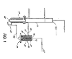
- a temperature controlled valve 60 is used for controlling the flow of weak liquor from the generator 11 to an absorber (not shown).
- the valve is controlled by a temperature-sensing bulb 62 charged with a composition that produces pressure responsive to the temperature sensed by the bulb.
- the temperature-sensing bulb is installed in thermal contact with the weak liquor in the generator or as it passes through piping or heat exchange coils of the generator. Changes in bulb pressure resulting from changes in the pressure of the bulb charge composition, are directed to a moveable member such as a diaphragm or bellows in the valve resulting in opening and closing the valve in response to the pressure changes, or pressure differential between surfaces of the diaphragm.
- a moveable member such as a diaphragm or bellows in the valve resulting in opening and closing the valve in response to the pressure changes, or pressure differential between surfaces of the diaphragm.
- valve 60 is positioned between pipes 45 and 47 which direct the weak liquor from the bottom of generator 11 to an absorber (not shown).
- the valve assembly includes a temperature-sensing bulb 62 in thermal contact with weak-liquor pickup tube 68.
- Valve 60 is opened and closed in response to the temperature sensed by the bulb 62 in pipe 68 which directs the weak liquor from the bottom of the generator to the GHX (generator heat exchange) coil 65 and pipe 45.
- the bulb may be placed in thermal contact with the bottom of the generator, either on the outside of the shell where it indirectly measures solution temperature at the bottom of the generator, or in direct thermal contact with solution inside the bottom of the generator.
- the temperature-sensing bulb may be installed at any desirable location, preferably where the ammonia-weak solution is at or near its bubble-point temperature.
- the valve is diaphragm-controlled with one side of the diaphragm exposed to the temperature-sensing bulb pressure and the other side to generator pressure.
- the valve components shown include inlet port 71, outlet port 72, diaphragm 73, actuator rod 74, valve plug 75, valve chamber 76 and spring 77.
- the valve 60 is installed so that the inlet port 71 of the valve receives weak liquor from the generator via pipe 45 and communicates with the valve chamber 76 which is exposed to the diaphragm 73, and the outlet port 72 communicates with pipe 47 for directing the weak liquor to the absorber assembly.
- the valve outlet port 72 is opened and closed in response to the pressure differential between the generator pressure and the temperature-sensing bulb pressure.
- the valve regulates weak solution flow rate so as to maintain concentration of ammonia in the weak solution within a desired range.
- the response of the valve depends on valve design parameters including diaphragm diameter, seat diameter, spring force, and bulb charge. Process parameters such as high-side and low-side pressures, i.e., pressures on the two sides of the valve plug, affect performance.
- a water-ammonia bulb charge works well for weak liquor flow control, with the amount of ammonia in the bulb being slightly higher than the desired concentration of ammonia in the weak liquor.
- Useful ammonia concentrations are between about 1-20% and preferably between about 3% and about 10%.
- Relatively constant weak liquor concentration is achieved using relatively low spring forces, combined with lower ammonia concentrations in the bulb charge. Increased spring force and slightly higher ammonia fraction in the bulb charge changes the valve response toward increased weak liquor ammonia concentration at higher pressures. Increasing the amount of ammonia in the weak liquor at higher pressures is often more desirable than constant concentration, since it helps to limit generator temperature at high ambient temperatures.
- bulb charge compositions may be substituted for the water/ammonia mixtures discussed above to obtain good performance characteristics.
- ammoniated complex compounds may be used, such as disclosed in U.S. Patent No. 4,848,994.
- a specific complex compound found to be useful is FeCl 2 ⁇ 2/6(NH 3 ).
- Hydrated BaCl 2 having a coordination step of 1-2 mols of water, i.e., BaCl 2 ⁇ 1/2 (H 2 O), or hydrated zeolites or carbon may also be used as suitable bulb charge.
- Weak liquor is shown routed through GHX coil 65 in the lower section of the generator whereby heat is transferred from the hot weak liquor to the generator.
- the weak liquor flow control valve 60 is installed downstream of the GHX coil which is advantageous since it allows for maximum heat transfer from the weak liquor to the generator prior to decreasing pressure of the weak solution, thus allowing maximum heat recovery from the solution before flashing or letdown to lower pressure. Also, locating the valve in the coolest part of the weak liquor stream permits the valve to be designed for lower maximum operating temperature.
- valves may be substituted for the diaphragm-operated valve described above. Any valve that responds to weak liquor temperature and/or pressure so as to maintain constant or near constant weak liquor concentration may be used. Another alternative is to use a valve responding directly to weak liquor concentration or to some physical property or condition correlated to weak liquor concentration.
- the apparatus may include one or more sensing devices for sensing or monitoring a condition of the absorption fluid, e.g. weak liquor, with the sensing device operatively communicating with a valve to control the valve in response to a sensed condition.
- the sensing device may be directly connected to the valve or indirectly operatively connected to the valve via an intermediate component, such as a control device, e.g. controller or microprocessor.
- Electronic valves operated in response to weak liquor temperature, pressure and/or concentration may also be used.
- such electronic valves may be continuously variable valves , or open-closed valves operated in a pulsed fashion, with pulse-width modulation or similar control algorithm to control the amount of the time the valve is open.
- a pulse-width operation controlled valve may be responsive to generator temperature, pressure or other physical properties or conditions correlated to weak solution concentration, or could be set to provide two or more different flow rates in response to operating conditions of the absorption system.
- Fig. 2 schematically illustrates an aqua-ammonia generator absorber heat-exchange (GAX) chiller system with continuous control of weak liquor flow using a valve as shown in Fig. 1.
- GX aqua-ammonia generator absorber heat-exchange
- the major components of the chiller system include an absorber assembly 10 comprising an absorber 12 and an absorber heat exchange section 30 which includes an absorber heat exchanger 31, sometimes referred to as a solution cooled absorber (SCA), and a GAX heat exchanger 33.
- SCA solution cooled absorber
- the generator assembly 11 shown includes a generator heat exchanger 15, a boiler 26 having a burner 19 for heating and vaporizing the solution, an adiabatic section 16, and a rectifier section 17 with reflux coil 13.
- the burner may be of a single, multiple or variable capacity type, and may include a combustion air pre-heater.
- a condenser 14 and an evaporator 20 are the other major components of the system.
- the chiller system may also include a subcooler 52 for precooling refrigerant from the condenser with cold gaseous refrigerant from the evaporator.
- the absorber and condenser heat exchangers may be air or liquid cooled, and the rectifier 17 may be cooled by solution or water.
- Such a GAX chiller is well-known in the art, for example, U.S. Patent Nos. 5,490,393 and 5,367,884, and in the aforesaid Modahl et al. publication.
- the relatively cool refrigerant-rich absorption fluid solution is pumped from the absorber via pipe 46 to heat exchange coil 13 within rectifier 17 after which it is directed via pipe 49 to the absorber heat exchanger 31 and GAX heat exchanger 33.
- a flow splitter 32 splits the ammonia-rich absorption fluid (rich liquor) passing from absorber heat exchanger (SCA) 31, a first portion to the generator via pipe 48 and a second portion to GAX heat exchanger 33 and then to the generator via pipe 50.
- the refrigerant vapor from evaporator 20 is directed via pipe 44 to the absorber assembly 10.
- Weak absorption fluid or weak liquor is directed to the absorber assembly 10 from the generator via pipe 45, valve 60 and pipe 47.
- the weak solution from the generator passes over the GAX heat exchanger 33 inside the absorber and over the absorber heat exchanger 31, it absorbs ammonia vapor.
- the advantages of a GAX system with flow split of a portion of the rich absorption fluid through the GAX heat exchanger are discussed in more detail in the aforesaid references, particularly in the Modahl et al. publication and the '884 patent.
- the present invention is not to be limited by the method of recovering GAX heat, whether it is by strong liquor, weak liquor, or a secondary fluid. Further, of strong liquor GAX recovery systems, the present invention is not to be limited by location of the flow split of rich liquor into GAX and non-GAX streams. In the Fig.
- the rich liquor is split at flow splitter 32' whereby a portion of rich liquor is directed to the generator via pipe 48' before rich liquor enters the SCA and GAX heat exchangers, whereas in Fig. 2 rich liquor flow splitter 32 is located between the SCA and GAX heat exchangers.
- the present invention is not limited to a GAX system and may be used in a conventional absorber heat exchange system, although the more efficient GAX cycle is preferred.
- the Fig. 2 embodiment is especially well suited for operation with continuously variable speed burner control.
- Fig. 3 schematically illustrates another embodiment of an aqua-ammonia chiller utilizing active weak liquor flow control.
- Active control is especially advantageous in a system having a variable speed or multiple speed burner.
- weak liquor flow may be changed in discrete steps and is especially well suited for operation with discrete burner speed control.
- Discrete control of weak liquor flow is especially advantageous in a system having a burner with 2 or more discrete speeds.
- Such apparatus is disclosed in U.S. Patent Application Serial No. 10/125,125, filed April 16, 2002 (ROCKYR.113A).
- the weak liquor flow from generator assembly 11 to absorber assembly 10 is directed along pipe 47 to splitter 51 to first and second piping 55 and 70, respectively.
- First piping 55 includes an actively controlled valve 56 and first restrictor 57.
- Second piping 70 includes a second restrictor 59. These two weak liquor flows provide high and low flow to accommodate weak solution concentrations within desired concentration ranges.
- valve 56 is opened and weak liquor flowing from the generator to the absorber via pipe 47 splits at flow splitter 51, with a first portion passing through pipe 55, valve 56 and restriction 57, and a second portion passing through pipe 70 and restriction 59.
- valve 56 is closed and all weak liquor flowing to the absorber passes through pipe 70 and restriction 59.
- Restrictions 57 and 59 may be any combination of orifices, capillary tubes, nozzles, or other fluid flow resistance elements known to those skilled in the art.
- Flow switching may be accomplished in response to changing operating conditions, such as ambient or load temperatures or weak solution concentrations, so as to maintain desired concentration range. Reduced weak liquor flow rates may also be used to enhance absorption system startup. Increased weak solution flow may be used to achieve short-term increases in cooling capacity.
- a controller 58 operatively communicates with valve control device 87 which operates to open and close valve 56 for controlling the flow rate of weak liquor.
- the valve opening may be variably controlled or a valve which is open or closed.
- the valve may be mechanical or electronic.
- the controller is operatively connected to temperature-sensing device 53 in thermal contact with the bottom of generator 11 and operates valve 56 in response to the temperature sensed by device 53.
- Temperature-sensing device 53 may be placed within the generator in direct thermal contact with the solution inside the bottom of the generator rather than on the outside shell.
- a device for measuring some other physical property or condition of the weak liquor such as refrigerant concentration, or a condition related to the weak liquor condition, or for sensing a condition of the apparatus or system such as load related conditions, for example, supply and/or return water temperature, or burner speed, may be substituted for temperature-sensing device 53 or used in combination with temperature sensing.
- load related conditions for example, supply and/or return water temperature, or burner speed
- the controller may also be thermostatically operated for controlling the valve opening whereby generator heating and weak liquor flow are changed in response to temperature conditions for which the heating and/or cooling system is used.
- controller 58 may incorporate pulse-width modulation control algorithm software or firmware for controlling operation of valve 56 and cycling the valve to rapidly open and close, and the controller or microprocessor configured to operate using pulsed-width modulation in response to changes in temperature, pressure, concentrations, etc.
- Electronic control of the weak solution flow and/or the burner firing rate may be based on sensing of the building load or one or more parameters representing the load.
- chilled water supply or return air temperature is one measure of the relative capacities of the chiller versus the building load.
- the dropping of the temperature of the chilled water supply (or return) below a previously determined set point temperature is an indication that the chiller is operating at a greater capacity than is needed by the building load.
- one or more of the weak solution control valve(s) would be closed or modulated more towards closing to reduce flow of weak solution, and, in conjunction, the burner would be modulated to reduce the firing rate.
- one or more of the weak solution valve(s) would open or be modulated more towards opening to increase the flow of weak solution, and, in conjunction, the burner would be modulated to increase the firing rate.
- Electronic control apparatus such as a controller or microprocessor such as described above, operatively connected to one or more components which sense the building load and/or parameters such as described may be used.
- valving i.e., one or more valves
- Figs. 4a-f are illustrative of examples of different types of valving and flow restrictions which may be used.
- Fig. 4a illustrates the use of a valve that, when closed, still allows fluid flow, but with more flow resistance than when the valve is open.
- An example of such a valve is one in which a hole is drilled in the valve plug, whereby a small fluid flow passes through the small orifice drilled in the plug when the plug is seated, and when the plug is lifted from the valve seat, greater fluid flow passes through the larger restriction defined by the valve seat.
- a valve may be operated by a solenoid, or other type of control.
- Fig. 4b illustrates a similar drilled valve having a small and a large restriction when closed or opened, respectively, used in series with a restriction providing an additional flow resistance, which may be used either upstream or downstream of the valve.
- Fig. 4c a parallel resistance in a by-pass line is used in combination with a valve.
- the valve may be drilled as previously described, or it may be fully closed or opened. Again, the fixed resistance used in the same line with the valve may be upstream or downstream from the valve.
- Fig. 4d illustrates series of resistances with a single valve used to by-pass one resistance for high-flow.
- valve may be drilled for high and low flow, or have variable valve openings, either of which valves may be controlled.
- Fig. 4e shows parallel flow restrictions with a valve in series with each restriction. Such an embodiment may be preferred to the embodiment illustrated in Fig. 4c when it is desired to terminate weak solution flow completely, for example, for shutdown or other operational reasons.
- the above valve and restriction embodiments are useful for two weak liquor flow modes, high and low flow, and for two burner speed systems.
- Fig. 4f illustrates an example of valving and flow restrictions for a three-speed or three-step flow control. It will be understood that different combinations of valve and flow restrictions may be used, expandable to any desired number of weak liquor fluid flow controls. Any one or more of the valves may be operated for being fully opened or closed, such as a solenoid-operated valve, or may be controlled for variable opening.
- a valve and temperature-sensing bulb are used for controlling refrigerant flow to the evaporator and controlling vapor superheat.
- a TXV 40 is positioned along pipe 42 for controlling the flow of refrigerant to evaporator 20.
- a temperature-sensing bulb 23 is positioned at or near the evaporator outlet on pipe 44, with a pressure conduit 25 communicating between the temperature-sensing bulb 23 and valve 40.
- a preferred valve used in the apparatus of the invention is a pulsed operation control valve disclosed in U.S. Patent No. 5,675,982. The use and operation of the valve for controlling superheat in such an apparatus is described in more detail in copending application Serial No. 10/125,125, filed April 16, 2002 (ROCKYR.104A).
- the absorber 12 may be air cooled as illustrated in Fig. 2 or may be cooled by refrigerant such as described in U.S. Patent Re. 36,684.
- Fig. 3 illustrates a portion of a refrigerant loop comprising a heat exchanger coil 84 in which condensed refrigerant supplied from condenser 14 is at least partially vaporized for cooling the absorber.
- the apparatus may include a reservoir (not shown) for the condensed refrigerant.
- the refrigerant loop includes piping 83 which communicates with piping 85 for directing the vaporized refrigerant from the absorber heat exchanger coil where it is combined with refrigerant vapor from the rectifier 17 to piping 41 to the condenser 14.
- the rectifier 17 also preferably includes a reflux coil 13 for cooling and rectifying the vapor by heating and/or vaporizing refrigerant in the reflux coil or cooling coil.
- Such a refrigerant loop is also preferably used with valving such as one or more valves and more preferably a four-way valve for reversing refrigerant flow as disclosed in Re. 36,684.
- valving such as one or more valves and more preferably a four-way valve for reversing refrigerant flow as disclosed in Re. 36,684.
- Such a valve-controlled refrigerant loop selectively directs the refrigerant to and from the condenser and the evaporator, each of which may alternately function to evaporate or condense refrigerant in a heat pump-type system.
- the above-described weak-liquor flow control and the absorber cooling and system heat rejection may be used in a dual-temperature appliance incorporating the aforesaid components and having a refrigerant loop in which refrigerant flow is not reversed and the condenser and evaporator heat exchange functions are not reversed.
Landscapes
- Engineering & Computer Science (AREA)
- Physics & Mathematics (AREA)
- Mechanical Engineering (AREA)
- Thermal Sciences (AREA)
- General Engineering & Computer Science (AREA)
- Sorption Type Refrigeration Machines (AREA)
- Seasonings (AREA)
Claims (21)
- Wasser-Ammoniak Absorptionskühl- und/oder -heizvorrichtung, umfassend:einen Absorberaufbau (10), einen Generatoraufbau (11), einen Kondensator (14), einen Verdampfer (20), einen Kühlmittelkreislauf umfassend Rohrleitungen (41, 42, 43, 44) zur Leitung von Kühlmittel zwischen Absorberaufbau, Generatoraufbau, Kondensator und Verdampfer, einen Absorptionsflüssigkeitskreislauf zur Leitung von Absorptionsflüssigkeit zwischen dem Absorberaufbau und dem Generatoraufbau, wobei der Absorptionsflüssigkeitskreislauf erste Rohrleitungen (46) zur Leitung ammoniakreicher Absorptionsflüssigkeit vom Absorberaufbau zum Generatoraufbau und zweite Rohrleitungen (45, 47) zur Leitung ammoniakarmer Absorptionsflüssigkeit vom Generatoraufbau zum Absorberaufbau enthält, und eine Ventilanordnung (60, 56) umfassend ein oder mehrere Ventile, die zum Öffnen und Schließen mit den zweiten Rohrleitungen zusammenwirken, um den Durchfluss von schwacher Absorptionsflüssigkeit darin zu regulieren, wobei die Vorrichtung charakterisiert ist durch eine zur Messung einer Beschaffenheit der ammoniakarmen Absorptionsflüssigkeit stromaufwärts des einen oder der mehreren Ventile platzierte Messeinrichtung (62, 53), die wirkend mit dem einen oder den mehreren Ventilen kommuniziert, um das eine Ventil oder die mehreren Ventile als Reaktion auf die gemessene Beschaffenheit zu öffnen und/oder zu schließen, wobei die gemessene Beschaffenheit eine gemessene Temperatur, Konzentration oder damit korrelierende Eigenschaft oder Beschaffenheit der ammoniakarmen Absorptionsflüssigkeit ist, um die Ammoniakkonzentration in der schwachen Lösung innerhalb des erwünschten Bereiches zu halten.
- Vorrichtung nach Anspruch 1, in der die Messeinrichtung einen Temperaturwächter (62) umfasst, der zur Überwachung der Temperatur der ammoniakarmen Absorptionsflüssigkeit im Generatoraufbau, wo die Lösung an oder nahe an ihrer Gasentlösungstemperatur ist, angeordnet ist.
- Vorrichtung nach Anspruch 2, in der die Ventilanordnung (60) ein von einem beweglichen Element (73) betriebenes Ventil (75) umfasst, in der der Temperaturwächter ein Kolben-Temperaturfühler ist, und in der eine erste Seite des beweglichen Elements dem Kolbendruck ausgesetzt ist und eine zweite Seite davon dem Generatordruck oder der ammoniakarmen Absorptionsflüssigkeit bei oder nahe am Generatordruck, wobei der Durchfluss der ammoniakarmen Absorptionsflüssigkeit durch das Öffnen und Schließen des Ventils als Reaktion auf die Druckdifferenz zwischen Kolbendruck und Generatordruck reguliert wird.
- Vorrichtung nach Anspruch 1, in der der Absorber eine Wärmetauscherschlange (84) in Flüssigkeitsverbindung mit dem Kühlmittelkreislauf enthält, wobei kondensiertes Kühlmittel zu dieser Wärmetauscherschlange geleitet und darin zur Kühlung des Absorbers zumindest teilweise verdampft wird, und in der der Kühlmittelkreislauf Rohrleitungen (83, 85) zur Leitung verdampften Kühlmittels von der Absorber-Wärmetauscherschlange und vom Generatoraufbau zum Kondensator enthält.
- Vorrichtung nach Anspruch 2, umfassend einen Rücklaufverflüssiger (17) und eine darin befindliche Kühlschlange (13) in Flüssigkeitsverbindung mit dem Kühlmittelkreislauf, wobei kondensiertes Kühlmittel zur Kühlschlange geleitet und darin zur Kühlung des Rücklaufverflüssigers erhitzt und/oder zumindest teilweise verdampft wird, und in der der Kühlmittelkreislauf Rohrleitungen (41) zur Leitung erhitzten und/oder verdampften Kühlmittels von der Kühlschlange zum Kondensator enthält.
- Vorrichtung nach Anspruch 1, 2 oder 3, in der der Absorberaufbau (10) einen Absorber (12), einen Absorberwärmetauscher (31) und einen Generator/Absorber-Wärmetauscher (33) enthält, und wobei der Absorptionsflüssigkeitskreislauf eine oder mehrere Leitungen (46, 49) zur Leitung ammoniakreicher Absorptionsflüssigkeit im Absorberaufbau vom Absorber (12) zum Absorberwärmetauscher (31) und zum Generator/Absorber-Wärmetauscher (33) enthält.
- Vorrichtung nach Anspruch 1, in der die zweiten Rohrleitungen eine oder mehrere durchflusshemmende Einrichtung(en) (57, 59) in Reihe oder parallel zu einem oder mehreren der Ventile enthalten.
- Vorrichtung nach Anspruch 7, in der die zweiten Rohrleitungen einen Flussteiler (51) und eine Mehrzahl damit kommunizierender Leitungen (55, 70) zur Leitung von Teilen der ammoniakarmen Absorptionsflüssigkeit zum Ventil (56) beziehungsweise zur durchflusshemmenden Einrichtung (57) enthalten.
- Vorrichtung nach Anspruch 1, in der die zweiten Rohrleitungen (47) einen Flussteiler (51) und erste und zweite damit kommunizierende Leitungen (55, 70) enthalten, sowie ein Ventil (56) und/oder eine durchflusshemmende Einrichtung (57, 59) entlang der ersten und zweiten Leitungen.
- Vorrichtung nach Anspruch 1, wobei die gemessene Beschaffenheit eine lastabhängige Beschaffenheit umfasst.
- Vorrichtung nach Anspruch 10, wobei die lastabhängige Beschaffenheit die Zufuhr gekühlten Wassers und/oder die Rücklaufwassertemperatur umfasst.
- Vorrichtung nach Anspruch 1, wobei die gemessene Beschaffenheit die Brennerleistung umfasst.
- Vorrichtung nach Anspruch 1, wobei die gemessene Beschaffenheit Druck, Temperatur und/oder Konzentration der ammoniakarmen Absorptionsflüssigkeit umfasst.
- Vorrichtung nach Anspruch 1, worin die Messeinrichtung in Messkontakt mit der ammoniakarmen Absorptionsflüssigkeit steht.
- Vorrichtung nach Anspruch 1, umfassend einen Regler oder Mikroprozessor (58), der wirkend mit der Ventilanordnung (56) und der Messeinrichtung (53) kommuniziert.
- Vorrichtung nach Anspruch 15, in der das Ventil (56) mittels Steuerung per Pulsweitenmodulation betrieben wird.
- Vorrichtung nach Anspruch 1, umfassend eine wirkend mit dem einen oder den mehreren Ventilen verbundene Vorrichtung zur elektronischen Regelung, und ein oder mehrere mit der elektronischen Regelungsvorrichtung wirkend verbundene Elemente zur Erfassung von Gebäudelasten und/oder eines Parameters oder mehrerer Parameter davon.
- Vorrichtung nach Anspruch 17, worin der eine oder die mehreren Lastparameter die Temperatur des gekühlten Wassers oder die Rücklauftemperatur umfassen.
- Vorrichtung nach Anspruch 1, worin Kondensator (14) und Verdampfer (20) erste und zweite Wärmetauscher umfassen, die jeweils geeignet sind, als Kondensator oder Verdampfer zu arbeiten, wobei die Vorrichtung ein oder mehrere Ventile umfasst, das/die mit dem Kühlmittelkreislauf zur wahlweisen Umkehrung des Kühlmittelflusses zu den Wärmetauschern hin und davon weg zusammenwirkt/zusammenwirken.
- Vorrichtung nach Anspruch 1, weiter gekennzeichnet durch einen Kolben-Temperaturfühler in Wärmeübertragungsverbindung mit dem Verdampfer am oder nahe am Ausgang des Verdampfers und ein mit den Kühlmittelrohrleitungen (42, 43) zusammenwirkendes Kühlmittelsteuerungsventil (40), wobei das Kühlmittelsteuerungsventil einen dem Druck des Kolben-Temperaturfühlers ausgesetzten Druckanschluss sowie ein diesem Druckanschluss ausgesetztes bewegliches und auf den Kolbendruck reagierendes Element zum Betrieb des Ventils und zur Regulierung des Durchflusses von Kühlmittel in Reaktion zur vom Kolben-Temperaturfühler erfassten Temperatur enthält, wobei das bewegliche Element eine erste dem Druck des Kolben-Temperaturfühlers ausgesetzte Seite und eine zweite dem Verdampferdruck ausgesetzte Seite hat, wobei das bewegliche Element das Kühlmittelsteuerungsventil veranlasst, in Reaktion auf den Druckunterschied zwischen dem Kolben-Temperaturfühler und dem Verdampfer zu arbeiten, und wobei der Kolben-Temperaturfühler oberhalb des beweglichen Elements platziert ist.
- Vorrichtung nach Anspruch 20, wobei das Kühlmittelsteuerungsventil ein Steuerventil mit gepulstem Betrieb umfasst, welches umfasst:einen Eingangsanschluss in Verbindung mit dem Kondensator, umfassend einen Flusseingangsbereich zum Empfang von kondensiertem Kühlmittel, und ein Ventil zum Öffnen und Schließen des Eingangsanschlusses;einen Ausgangsanschluss umfassend einen Flussausgangsbereich, der mit dem Verdampfer zur Leitung von flüssigem Kühlmittel dorthin kommuniziert;eine Ventilkavität zwischen dem Eingangsanschluss und dem Ausgangsanschluss in offener Verbindung dazwischen;wobei das Ventil auf den Druck in der Kavität zum Betrieb des Ventils und zur Regulierung des Öffnens und Schließens des Eingangsanschlusses reagiert, und wobei ein höherer Druck darin das Ventil zum Schließen des Eingangsanschlusses beeinflusst und ein niedrigerer Druck darin das Ventil zum Öffnen des Eingangsanschlusses beeinflusst; und
wobei der Flusseingangsbereich mindestens zweimal so groß ist wie der Flussausgangsbereich, wodurch ein Öffnen des Eingangsanschlusses für schnellen Druckaufbau in der Kavität sorgt und für schnelles Schließen davon nach jedem Öffnen.
Applications Claiming Priority (3)
| Application Number | Priority Date | Filing Date | Title |
|---|---|---|---|
| US10/125,298 US6748752B2 (en) | 2002-04-16 | 2002-04-16 | Apparatus and method for weak liquor flow control in aqua-ammonia absorption cycles |
| US125298 | 2002-04-16 | ||
| PCT/US2003/010794 WO2003089850A1 (en) | 2002-04-16 | 2003-04-04 | Apparatus and method for weak liquor flow control in aqua-ammonia absorption cycles |
Publications (2)
| Publication Number | Publication Date |
|---|---|
| EP1495271A1 EP1495271A1 (de) | 2005-01-12 |
| EP1495271B1 true EP1495271B1 (de) | 2007-02-21 |
Family
ID=28790920
Family Applications (1)
| Application Number | Title | Priority Date | Filing Date |
|---|---|---|---|
| EP03718270A Expired - Lifetime EP1495271B1 (de) | 2002-04-16 | 2003-04-04 | Verfahren und vorrichtung zur durchsatzregelung der schwachen lösung in ammoniak/wasser-absorptionskreisläufen |
Country Status (11)
| Country | Link |
|---|---|
| US (1) | US6748752B2 (de) |
| EP (1) | EP1495271B1 (de) |
| AR (1) | AR039313A1 (de) |
| AT (1) | ATE354771T1 (de) |
| AU (1) | AU2003221692A1 (de) |
| CA (1) | CA2481989C (de) |
| DE (1) | DE60311974T2 (de) |
| ES (1) | ES2282613T3 (de) |
| MX (1) | MXPA04010086A (de) |
| SA (1) | SA03240127B1 (de) |
| WO (1) | WO2003089850A1 (de) |
Cited By (1)
| Publication number | Priority date | Publication date | Assignee | Title |
|---|---|---|---|---|
| US10648712B1 (en) | 2017-08-16 | 2020-05-12 | Florida A&M University | Microwave assisted hybrid solar vapor absorption refrigeration systems |
Families Citing this family (9)
| Publication number | Priority date | Publication date | Assignee | Title |
|---|---|---|---|---|
| US20040216322A1 (en) * | 2001-12-06 | 2004-11-04 | Nicholas Collier | Hairdryer |
| US8056360B2 (en) * | 2006-11-22 | 2011-11-15 | Paul Neilson Unmack | Absorption refrigeration protective controller |
| US20110308261A1 (en) * | 2008-12-19 | 2011-12-22 | Invensor Gmbh | Pressure-reducing element for splitting the recooling volume flow in sorption machines |
| IT1393708B1 (it) * | 2009-04-29 | 2012-05-08 | Guerra | Pompa di calore ad assorbimento per condizioni operative estreme |
| ITMI20090729A1 (it) | 2009-04-29 | 2010-10-30 | Marco Guerra | Pompa di calore ad assorbimento con modulazione della potenza del bruciatore |
| IT1399062B1 (it) * | 2010-03-22 | 2013-04-05 | Guerra | Pompa di calore ad assorbimento per condizioni operative di sovralimentazione del generatore |
| US10174977B2 (en) * | 2012-11-21 | 2019-01-08 | Vertiv Corporation | Apparatus and method for subcooling control based on superheat setpoint control |
| WO2015048858A1 (en) * | 2013-10-06 | 2015-04-09 | Tranquility Group Pty Ltd | System and apparatus for electronic control of an absorption refrigeration system |
| US11839062B2 (en) | 2016-08-02 | 2023-12-05 | Munters Corporation | Active/passive cooling system |
Family Cites Families (29)
| Publication number | Priority date | Publication date | Assignee | Title |
|---|---|---|---|---|
| US36684A (en) | 1862-10-14 | Improvement in tailors press-board holders | ||
| DE1401483A1 (de) | 1961-04-10 | 1969-02-06 | Ckd Praha Narodni Podnik | Regelsystem fuer Absorptionskuehleinrichtungen |
| US3826104A (en) * | 1972-06-30 | 1974-07-30 | Carrier Corp | Apparatus for charging absorption refrigeration systems |
| USRE30252E (en) * | 1974-11-14 | 1980-04-08 | Carrier Corporation | High temperature heat recovery in refrigeration |
| US4246761A (en) * | 1978-10-30 | 1981-01-27 | Allied Chemical Corporation | Absorption heat pump control system |
| FR2454591A1 (fr) | 1979-04-17 | 1980-11-14 | Inst Francais Du Petrole | Procede perfectionne de production de froid et/ou de chaleur au moyen d'un cycle a absorption |
| US4596122A (en) * | 1982-09-30 | 1986-06-24 | Joh. Vaillant Gmbh | Sorption heat pump |
| DE3344421A1 (de) | 1983-12-08 | 1985-06-20 | Robert Bosch Gmbh, 7000 Stuttgart | Heizungsanlage mit einer absorptionswaermepumpe |
| DE3609306A1 (de) | 1985-03-16 | 1986-10-02 | Joh. Vaillant Gmbh U. Co, 5630 Remscheid | Verfahren zum steuern der leistung |
| DE3518276C1 (de) | 1985-05-22 | 1991-06-27 | Deutsche Forschungs- und Versuchsanstalt für Luft- und Raumfahrt e.V., 5300 Bonn | Verfahren zum Betrieb einer Waermepumpenanlage und zur Durchfuehrung dieses Verfahrens geeignete Waermepumpenanlage |
| US4724679A (en) * | 1986-07-02 | 1988-02-16 | Reinhard Radermacher | Advanced vapor compression heat pump cycle utilizing non-azeotropic working fluid mixtures |
| US4848994A (en) | 1987-11-02 | 1989-07-18 | Uwe Rockenfeller | System for low temperature refrigeration and chill storage using ammoniated complex compounds |
| US5024063A (en) | 1990-05-11 | 1991-06-18 | Erickson Donald C | Branched gax absorption vapor compressor |
| US5367884B1 (en) | 1991-03-12 | 1996-12-31 | Phillips Eng Co | Generator-absorber-heat exchange heat transfer apparatus and method and use thereof in a heat pump |
| US5271235A (en) | 1991-03-12 | 1993-12-21 | Phillips Engineering Company | High efficiency absorption cycle of the gax type |
| US5490393A (en) | 1994-03-31 | 1996-02-13 | Robur Corporation | Generator absorber heat exchanger for an ammonia/water absorption refrigeration system |
| US5586447A (en) * | 1994-07-20 | 1996-12-24 | Gas Research Institute | Concentration control in an absorption chiller |
| US5572884A (en) * | 1994-11-04 | 1996-11-12 | The Ohio State University Research Foundation | Heat pump |
| US5771710A (en) | 1995-03-17 | 1998-06-30 | Gas Research Institute | Thermosyphon cooled absorber for air cooled absorption cycles |
| US5548971A (en) | 1995-06-14 | 1996-08-27 | Rocky Research | Method for use of liquid/vapor ammonia absorption systems in unitary HVAC systems |
| KR100418993B1 (ko) | 1995-08-01 | 2004-05-20 | 산요덴키가부시키가이샤 | 흡수식냉동장치 |
| JP3732877B2 (ja) | 1995-09-29 | 2006-01-11 | 三洋電機株式会社 | 吸収式冷凍機の制御方法及び制御装置 |
| US5791157A (en) * | 1996-01-16 | 1998-08-11 | Ebara Corporation | Heat pump device and desiccant assisted air conditioning system |
| US5675982A (en) | 1996-04-26 | 1997-10-14 | Rocky Research | Pulsed operation control valve |
| SE9700008D0 (sv) * | 1997-01-02 | 1997-01-02 | Sjoeblom Hans | Värmemaskin |
| UA57849C2 (uk) * | 1998-09-04 | 2003-07-15 | Герхард КУНЦЕ | Абсорбційна холодильна машина |
| DE19916907C2 (de) | 1999-04-14 | 2002-12-05 | Heliotherm Solartechnik Ges M | Absorptionswärmepumpe und Verfahren zum Betrieb einer Absorptionswärmepumpe |
| US6718792B1 (en) | 2000-01-05 | 2004-04-13 | Rocky Research | Integrated aqua-ammonia chiller/heater |
| JP7399913B2 (ja) | 2021-08-11 | 2023-12-18 | プライムプラネットエナジー&ソリューションズ株式会社 | 電池の製造方法 |
-
2002
- 2002-04-16 US US10/125,298 patent/US6748752B2/en not_active Expired - Lifetime
-
2003
- 2003-04-04 AT AT03718270T patent/ATE354771T1/de not_active IP Right Cessation
- 2003-04-04 CA CA2481989A patent/CA2481989C/en not_active Expired - Fee Related
- 2003-04-04 AU AU2003221692A patent/AU2003221692A1/en not_active Abandoned
- 2003-04-04 DE DE60311974T patent/DE60311974T2/de not_active Expired - Lifetime
- 2003-04-04 ES ES03718270T patent/ES2282613T3/es not_active Expired - Lifetime
- 2003-04-04 MX MXPA04010086A patent/MXPA04010086A/es active IP Right Grant
- 2003-04-04 EP EP03718270A patent/EP1495271B1/de not_active Expired - Lifetime
- 2003-04-04 WO PCT/US2003/010794 patent/WO2003089850A1/en not_active Ceased
- 2003-04-15 AR ARP030101309A patent/AR039313A1/es not_active Application Discontinuation
- 2003-05-21 SA SA3240127A patent/SA03240127B1/ar unknown
Cited By (1)
| Publication number | Priority date | Publication date | Assignee | Title |
|---|---|---|---|---|
| US10648712B1 (en) | 2017-08-16 | 2020-05-12 | Florida A&M University | Microwave assisted hybrid solar vapor absorption refrigeration systems |
Also Published As
| Publication number | Publication date |
|---|---|
| US20030192330A1 (en) | 2003-10-16 |
| HK1071421A1 (en) | 2005-07-15 |
| WO2003089850A1 (en) | 2003-10-30 |
| DE60311974D1 (de) | 2007-04-05 |
| AU2003221692A1 (en) | 2003-11-03 |
| SA03240127B1 (ar) | 2008-03-05 |
| EP1495271A1 (de) | 2005-01-12 |
| AR039313A1 (es) | 2005-02-16 |
| US6748752B2 (en) | 2004-06-15 |
| MXPA04010086A (es) | 2004-12-13 |
| ES2282613T3 (es) | 2007-10-16 |
| CA2481989C (en) | 2011-10-11 |
| DE60311974T2 (de) | 2007-10-31 |
| ATE354771T1 (de) | 2007-03-15 |
| CA2481989A1 (en) | 2003-10-30 |
Similar Documents
| Publication | Publication Date | Title |
|---|---|---|
| EP1244890B1 (de) | Wasser und amoniak verwendende einheit zum kühlen und heizen | |
| US6748752B2 (en) | Apparatus and method for weak liquor flow control in aqua-ammonia absorption cycles | |
| EP3455564B1 (de) | Steuerungsverfahren für eine sorptionswärmepumpe | |
| CA2462629C (en) | Method and apparatus for turbulent refrigerant flow to evaporator | |
| CA2426526C (en) | Phase-change heat transfer coupling for aqua-ammonia absorption systems | |
| CA2481993C (en) | Aqua-ammonia absorption system with variable speed burner | |
| US6584788B1 (en) | Apparatus and method for improved performance of aqua-ammonia absorption cycles | |
| HK1071421B (en) | Apparatus and method for weak liquor flow control in aqua-ammonia absorption cycles | |
| JP3210773B2 (ja) | 二重効用吸収式冷凍機 | |
| JP4330522B2 (ja) | 吸収式冷凍機の運転制御方法 | |
| JP3429904B2 (ja) | 吸収式冷凍機 | |
| KR19980050604A (ko) | 냉동사이클장치 | |
| JPS5828902B2 (ja) | 蒸気↓−排ガス切換形吸収冷凍機 | |
| KR980010240A (ko) | 암모니아 흡수식 냉난방기 | |
| JPH09236353A (ja) | 吸収式ヒートポンプ | |
| JPH04203860A (ja) | 吸収冷温水装置とその運転方法 | |
| JPH04203862A (ja) | 冷温水併給式吸収冷凍機 | |
| JPH11257786A (ja) | 吸収式冷熱発生装置 |
Legal Events
| Date | Code | Title | Description |
|---|---|---|---|
| PUAI | Public reference made under article 153(3) epc to a published international application that has entered the european phase |
Free format text: ORIGINAL CODE: 0009012 |
|
| 17P | Request for examination filed |
Effective date: 20040927 |
|
| AK | Designated contracting states |
Kind code of ref document: A1 Designated state(s): AT BE BG CH CY CZ DE DK EE ES FI FR GB GR HU IE IT LI LU MC NL PT RO SE SI SK TR |
|
| AX | Request for extension of the european patent |
Extension state: AL LT LV MK |
|
| RIN1 | Information on inventor provided before grant (corrected) |
Inventor name: KIROL, LANCE Inventor name: ROCKENFELLER, UWE Inventor name: SARKISIAN, PAUL |
|
| REG | Reference to a national code |
Ref country code: HK Ref legal event code: DE Ref document number: 1071421 Country of ref document: HK |
|
| GRAP | Despatch of communication of intention to grant a patent |
Free format text: ORIGINAL CODE: EPIDOSNIGR1 |
|
| GRAS | Grant fee paid |
Free format text: ORIGINAL CODE: EPIDOSNIGR3 |
|
| GRAA | (expected) grant |
Free format text: ORIGINAL CODE: 0009210 |
|
| AK | Designated contracting states |
Kind code of ref document: B1 Designated state(s): AT BE BG CH CY CZ DE DK EE ES FI FR GB GR HU IE IT LI LU MC NL PT RO SE SI SK TR |
|
| PG25 | Lapsed in a contracting state [announced via postgrant information from national office to epo] |
Ref country code: FI Free format text: LAPSE BECAUSE OF FAILURE TO SUBMIT A TRANSLATION OF THE DESCRIPTION OR TO PAY THE FEE WITHIN THE PRESCRIBED TIME-LIMIT Effective date: 20070221 Ref country code: LI Free format text: LAPSE BECAUSE OF FAILURE TO SUBMIT A TRANSLATION OF THE DESCRIPTION OR TO PAY THE FEE WITHIN THE PRESCRIBED TIME-LIMIT Effective date: 20070221 Ref country code: SI Free format text: LAPSE BECAUSE OF FAILURE TO SUBMIT A TRANSLATION OF THE DESCRIPTION OR TO PAY THE FEE WITHIN THE PRESCRIBED TIME-LIMIT Effective date: 20070221 Ref country code: AT Free format text: LAPSE BECAUSE OF FAILURE TO SUBMIT A TRANSLATION OF THE DESCRIPTION OR TO PAY THE FEE WITHIN THE PRESCRIBED TIME-LIMIT Effective date: 20070221 Ref country code: DK Free format text: LAPSE BECAUSE OF FAILURE TO SUBMIT A TRANSLATION OF THE DESCRIPTION OR TO PAY THE FEE WITHIN THE PRESCRIBED TIME-LIMIT Effective date: 20070221 Ref country code: NL Free format text: LAPSE BECAUSE OF FAILURE TO SUBMIT A TRANSLATION OF THE DESCRIPTION OR TO PAY THE FEE WITHIN THE PRESCRIBED TIME-LIMIT Effective date: 20070221 Ref country code: CH Free format text: LAPSE BECAUSE OF FAILURE TO SUBMIT A TRANSLATION OF THE DESCRIPTION OR TO PAY THE FEE WITHIN THE PRESCRIBED TIME-LIMIT Effective date: 20070221 Ref country code: BE Free format text: LAPSE BECAUSE OF FAILURE TO SUBMIT A TRANSLATION OF THE DESCRIPTION OR TO PAY THE FEE WITHIN THE PRESCRIBED TIME-LIMIT Effective date: 20070221 |
|
| REG | Reference to a national code |
Ref country code: GB Ref legal event code: FG4D |
|
| REG | Reference to a national code |
Ref country code: CH Ref legal event code: EP |
|
| REF | Corresponds to: |
Ref document number: 60311974 Country of ref document: DE Date of ref document: 20070405 Kind code of ref document: P |
|
| REG | Reference to a national code |
Ref country code: IE Ref legal event code: FG4D |
|
| REG | Reference to a national code |
Ref country code: HK Ref legal event code: GR Ref document number: 1071421 Country of ref document: HK |
|
| PG25 | Lapsed in a contracting state [announced via postgrant information from national office to epo] |
Ref country code: SE Free format text: LAPSE BECAUSE OF FAILURE TO SUBMIT A TRANSLATION OF THE DESCRIPTION OR TO PAY THE FEE WITHIN THE PRESCRIBED TIME-LIMIT Effective date: 20070521 |
|
| PG25 | Lapsed in a contracting state [announced via postgrant information from national office to epo] |
Ref country code: BG Free format text: LAPSE BECAUSE OF EXPIRATION OF PROTECTION Effective date: 20070522 |
|
| PG25 | Lapsed in a contracting state [announced via postgrant information from national office to epo] |
Ref country code: PT Free format text: LAPSE BECAUSE OF FAILURE TO SUBMIT A TRANSLATION OF THE DESCRIPTION OR TO PAY THE FEE WITHIN THE PRESCRIBED TIME-LIMIT Effective date: 20070723 |
|
| NLV1 | Nl: lapsed or annulled due to failure to fulfill the requirements of art. 29p and 29m of the patents act | ||
| ET | Fr: translation filed | ||
| REG | Reference to a national code |
Ref country code: CH Ref legal event code: PL |
|
| REG | Reference to a national code |
Ref country code: ES Ref legal event code: FG2A Ref document number: 2282613 Country of ref document: ES Kind code of ref document: T3 |
|
| PG25 | Lapsed in a contracting state [announced via postgrant information from national office to epo] |
Ref country code: SK Free format text: LAPSE BECAUSE OF FAILURE TO SUBMIT A TRANSLATION OF THE DESCRIPTION OR TO PAY THE FEE WITHIN THE PRESCRIBED TIME-LIMIT Effective date: 20070221 |
|
| PLBE | No opposition filed within time limit |
Free format text: ORIGINAL CODE: 0009261 |
|
| STAA | Information on the status of an ep patent application or granted ep patent |
Free format text: STATUS: NO OPPOSITION FILED WITHIN TIME LIMIT |
|
| PG25 | Lapsed in a contracting state [announced via postgrant information from national office to epo] |
Ref country code: CZ Free format text: LAPSE BECAUSE OF FAILURE TO SUBMIT A TRANSLATION OF THE DESCRIPTION OR TO PAY THE FEE WITHIN THE PRESCRIBED TIME-LIMIT Effective date: 20070221 Ref country code: RO Free format text: LAPSE BECAUSE OF FAILURE TO SUBMIT A TRANSLATION OF THE DESCRIPTION OR TO PAY THE FEE WITHIN THE PRESCRIBED TIME-LIMIT Effective date: 20070221 |
|
| 26N | No opposition filed |
Effective date: 20071122 |
|
| PG25 | Lapsed in a contracting state [announced via postgrant information from national office to epo] |
Ref country code: GR Free format text: LAPSE BECAUSE OF FAILURE TO SUBMIT A TRANSLATION OF THE DESCRIPTION OR TO PAY THE FEE WITHIN THE PRESCRIBED TIME-LIMIT Effective date: 20070522 |
|
| PG25 | Lapsed in a contracting state [announced via postgrant information from national office to epo] |
Ref country code: IE Free format text: LAPSE BECAUSE OF NON-PAYMENT OF DUE FEES Effective date: 20070404 |
|
| PG25 | Lapsed in a contracting state [announced via postgrant information from national office to epo] |
Ref country code: EE Free format text: LAPSE BECAUSE OF FAILURE TO SUBMIT A TRANSLATION OF THE DESCRIPTION OR TO PAY THE FEE WITHIN THE PRESCRIBED TIME-LIMIT Effective date: 20070221 |
|
| PG25 | Lapsed in a contracting state [announced via postgrant information from national office to epo] |
Ref country code: MC Free format text: LAPSE BECAUSE OF NON-PAYMENT OF DUE FEES Effective date: 20070430 |
|
| PG25 | Lapsed in a contracting state [announced via postgrant information from national office to epo] |
Ref country code: CY Free format text: LAPSE BECAUSE OF FAILURE TO SUBMIT A TRANSLATION OF THE DESCRIPTION OR TO PAY THE FEE WITHIN THE PRESCRIBED TIME-LIMIT Effective date: 20070221 |
|
| PG25 | Lapsed in a contracting state [announced via postgrant information from national office to epo] |
Ref country code: LU Free format text: LAPSE BECAUSE OF NON-PAYMENT OF DUE FEES Effective date: 20070404 |
|
| PG25 | Lapsed in a contracting state [announced via postgrant information from national office to epo] |
Ref country code: HU Free format text: LAPSE BECAUSE OF FAILURE TO SUBMIT A TRANSLATION OF THE DESCRIPTION OR TO PAY THE FEE WITHIN THE PRESCRIBED TIME-LIMIT Effective date: 20070822 Ref country code: TR Free format text: LAPSE BECAUSE OF FAILURE TO SUBMIT A TRANSLATION OF THE DESCRIPTION OR TO PAY THE FEE WITHIN THE PRESCRIBED TIME-LIMIT Effective date: 20070221 |
|
| REG | Reference to a national code |
Ref country code: FR Ref legal event code: PLFP Year of fee payment: 13 |
|
| REG | Reference to a national code |
Ref country code: FR Ref legal event code: PLFP Year of fee payment: 14 |
|
| REG | Reference to a national code |
Ref country code: FR Ref legal event code: PLFP Year of fee payment: 15 |
|
| REG | Reference to a national code |
Ref country code: FR Ref legal event code: PLFP Year of fee payment: 16 |
|
| PGFP | Annual fee paid to national office [announced via postgrant information from national office to epo] |
Ref country code: FR Payment date: 20190327 Year of fee payment: 17 |
|
| PGFP | Annual fee paid to national office [announced via postgrant information from national office to epo] |
Ref country code: IT Payment date: 20190419 Year of fee payment: 17 Ref country code: ES Payment date: 20190503 Year of fee payment: 17 Ref country code: DE Payment date: 20190319 Year of fee payment: 17 |
|
| PGFP | Annual fee paid to national office [announced via postgrant information from national office to epo] |
Ref country code: GB Payment date: 20190403 Year of fee payment: 17 |
|
| REG | Reference to a national code |
Ref country code: DE Ref legal event code: R119 Ref document number: 60311974 Country of ref document: DE |
|
| PG25 | Lapsed in a contracting state [announced via postgrant information from national office to epo] |
Ref country code: FR Free format text: LAPSE BECAUSE OF NON-PAYMENT OF DUE FEES Effective date: 20200430 Ref country code: DE Free format text: LAPSE BECAUSE OF NON-PAYMENT OF DUE FEES Effective date: 20201103 |
|
| GBPC | Gb: european patent ceased through non-payment of renewal fee |
Effective date: 20200404 |
|
| PG25 | Lapsed in a contracting state [announced via postgrant information from national office to epo] |
Ref country code: GB Free format text: LAPSE BECAUSE OF NON-PAYMENT OF DUE FEES Effective date: 20200404 |
|
| REG | Reference to a national code |
Ref country code: ES Ref legal event code: FD2A Effective date: 20210831 |
|
| PG25 | Lapsed in a contracting state [announced via postgrant information from national office to epo] |
Ref country code: IT Free format text: LAPSE BECAUSE OF NON-PAYMENT OF DUE FEES Effective date: 20200404 |
|
| PG25 | Lapsed in a contracting state [announced via postgrant information from national office to epo] |
Ref country code: ES Free format text: LAPSE BECAUSE OF NON-PAYMENT OF DUE FEES Effective date: 20200405 |
|
| P01 | Opt-out of the competence of the unified patent court (upc) registered |
Effective date: 20230830 |