EP1494583B1 - Elektrisches mess- und stimulationssystem zur platzierung eines nervenstimulators oder sensors - Google Patents
Elektrisches mess- und stimulationssystem zur platzierung eines nervenstimulators oder sensors Download PDFInfo
- Publication number
- EP1494583B1 EP1494583B1 EP02786417.2A EP02786417A EP1494583B1 EP 1494583 B1 EP1494583 B1 EP 1494583B1 EP 02786417 A EP02786417 A EP 02786417A EP 1494583 B1 EP1494583 B1 EP 1494583B1
- Authority
- EP
- European Patent Office
- Prior art keywords
- outer sheath
- sheath
- insertion system
- microstimulator
- microdevice
- Prior art date
- Legal status (The legal status is an assumption and is not a legal conclusion. Google has not performed a legal analysis and makes no representation as to the accuracy of the status listed.)
- Expired - Lifetime
Links
- 230000004936 stimulating effect Effects 0.000 title claims description 15
- 210000005036 nerve Anatomy 0.000 title description 104
- 239000000523 sample Substances 0.000 claims description 93
- 238000003780 insertion Methods 0.000 claims description 54
- 230000037431 insertion Effects 0.000 claims description 54
- 238000002513 implantation Methods 0.000 claims description 33
- 239000004020 conductor Substances 0.000 claims description 15
- 230000002232 neuromuscular Effects 0.000 claims description 14
- 230000000638 stimulation Effects 0.000 claims description 14
- 230000037361 pathway Effects 0.000 claims description 13
- 239000002184 metal Substances 0.000 claims description 2
- 230000000149 penetrating effect Effects 0.000 claims 2
- 230000035515 penetration Effects 0.000 claims 1
- 210000001519 tissue Anatomy 0.000 description 50
- 210000003205 muscle Anatomy 0.000 description 36
- 230000004044 response Effects 0.000 description 16
- WABPQHHGFIMREM-UHFFFAOYSA-N lead(0) Chemical compound [Pb] WABPQHHGFIMREM-UHFFFAOYSA-N 0.000 description 11
- 238000000034 method Methods 0.000 description 11
- FAPWRFPIFSIZLT-UHFFFAOYSA-M Sodium chloride Chemical compound [Na+].[Cl-] FAPWRFPIFSIZLT-UHFFFAOYSA-M 0.000 description 7
- 239000000463 material Substances 0.000 description 7
- 210000001169 hypoglossal nerve Anatomy 0.000 description 6
- 239000007943 implant Substances 0.000 description 6
- 230000008602 contraction Effects 0.000 description 5
- 239000004033 plastic Substances 0.000 description 5
- 238000001356 surgical procedure Methods 0.000 description 5
- 238000013459 approach Methods 0.000 description 4
- 239000004744 fabric Substances 0.000 description 4
- 230000033001 locomotion Effects 0.000 description 4
- 230000008569 process Effects 0.000 description 4
- 239000011780 sodium chloride Substances 0.000 description 4
- 230000008901 benefit Effects 0.000 description 3
- 239000000615 nonconductor Substances 0.000 description 3
- 206010033675 panniculitis Diseases 0.000 description 3
- 210000004304 subcutaneous tissue Anatomy 0.000 description 3
- NNJVILVZKWQKPM-UHFFFAOYSA-N Lidocaine Chemical compound CCN(CC)CC(=O)NC1=C(C)C=CC=C1C NNJVILVZKWQKPM-UHFFFAOYSA-N 0.000 description 2
- UELITFHSCLAHKR-UHFFFAOYSA-N acibenzolar-S-methyl Chemical compound CSC(=O)C1=CC=CC2=C1SN=N2 UELITFHSCLAHKR-UHFFFAOYSA-N 0.000 description 2
- 239000002775 capsule Substances 0.000 description 2
- 230000008878 coupling Effects 0.000 description 2
- 238000010168 coupling process Methods 0.000 description 2
- 238000005859 coupling reaction Methods 0.000 description 2
- 230000001939 inductive effect Effects 0.000 description 2
- 230000007383 nerve stimulation Effects 0.000 description 2
- 235000001968 nicotinic acid Nutrition 0.000 description 2
- 239000012811 non-conductive material Substances 0.000 description 2
- WYWIFABBXFUGLM-UHFFFAOYSA-N oxymetazoline Chemical compound CC1=CC(C(C)(C)C)=C(O)C(C)=C1CC1=NCCN1 WYWIFABBXFUGLM-UHFFFAOYSA-N 0.000 description 2
- 239000000243 solution Substances 0.000 description 2
- 238000012360 testing method Methods 0.000 description 2
- 238000002560 therapeutic procedure Methods 0.000 description 2
- 230000000007 visual effect Effects 0.000 description 2
- UCTWMZQNUQWSLP-VIFPVBQESA-N (R)-adrenaline Chemical compound CNC[C@H](O)C1=CC=C(O)C(O)=C1 UCTWMZQNUQWSLP-VIFPVBQESA-N 0.000 description 1
- 229930182837 (R)-adrenaline Natural products 0.000 description 1
- 206010003694 Atrophy Diseases 0.000 description 1
- 208000034347 Faecal incontinence Diseases 0.000 description 1
- 206010023204 Joint dislocation Diseases 0.000 description 1
- 208000029578 Muscle disease Diseases 0.000 description 1
- 206010049565 Muscle fatigue Diseases 0.000 description 1
- 208000021642 Muscular disease Diseases 0.000 description 1
- 239000004677 Nylon Substances 0.000 description 1
- 208000006011 Stroke Diseases 0.000 description 1
- 206010046543 Urinary incontinence Diseases 0.000 description 1
- 230000004913 activation Effects 0.000 description 1
- 230000037444 atrophy Effects 0.000 description 1
- 230000009286 beneficial effect Effects 0.000 description 1
- 210000001124 body fluid Anatomy 0.000 description 1
- 239000010839 body fluid Substances 0.000 description 1
- 238000005266 casting Methods 0.000 description 1
- 239000000919 ceramic Substances 0.000 description 1
- 238000004891 communication Methods 0.000 description 1
- 210000002808 connective tissue Anatomy 0.000 description 1
- 230000006378 damage Effects 0.000 description 1
- 238000000502 dialysis Methods 0.000 description 1
- 239000003989 dielectric material Substances 0.000 description 1
- 238000006073 displacement reaction Methods 0.000 description 1
- 230000009977 dual effect Effects 0.000 description 1
- 230000005611 electricity Effects 0.000 description 1
- 229960005139 epinephrine Drugs 0.000 description 1
- 230000000763 evoking effect Effects 0.000 description 1
- 239000003193 general anesthetic agent Substances 0.000 description 1
- 239000011521 glass Substances 0.000 description 1
- 210000003823 hyoid bone Anatomy 0.000 description 1
- 238000002347 injection Methods 0.000 description 1
- 239000007924 injection Substances 0.000 description 1
- 208000014674 injury Diseases 0.000 description 1
- 238000001990 intravenous administration Methods 0.000 description 1
- 229960004194 lidocaine Drugs 0.000 description 1
- 239000012528 membrane Substances 0.000 description 1
- 238000004377 microelectronic Methods 0.000 description 1
- 238000012986 modification Methods 0.000 description 1
- 230000004048 modification Effects 0.000 description 1
- 238000012544 monitoring process Methods 0.000 description 1
- 230000004118 muscle contraction Effects 0.000 description 1
- 230000004220 muscle function Effects 0.000 description 1
- 210000001989 nasopharynx Anatomy 0.000 description 1
- 229920001778 nylon Polymers 0.000 description 1
- 229960001528 oxymetazoline Drugs 0.000 description 1
- 238000002360 preparation method Methods 0.000 description 1
- 230000000452 restraining effect Effects 0.000 description 1
- 230000000717 retained effect Effects 0.000 description 1
- 239000000932 sedative agent Substances 0.000 description 1
- 230000001624 sedative effect Effects 0.000 description 1
- 210000000323 shoulder joint Anatomy 0.000 description 1
- 201000002859 sleep apnea Diseases 0.000 description 1
- 239000002195 soluble material Substances 0.000 description 1
- 238000007920 subcutaneous administration Methods 0.000 description 1
- 230000000451 tissue damage Effects 0.000 description 1
- 231100000827 tissue damage Toxicity 0.000 description 1
- 230000000699 topical effect Effects 0.000 description 1
- 230000008733 trauma Effects 0.000 description 1
- 230000002485 urinary effect Effects 0.000 description 1
- XLYOFNOQVPJJNP-UHFFFAOYSA-N water Substances O XLYOFNOQVPJJNP-UHFFFAOYSA-N 0.000 description 1
- 229940072358 xylocaine Drugs 0.000 description 1
Images










Classifications
-
- A—HUMAN NECESSITIES
- A61—MEDICAL OR VETERINARY SCIENCE; HYGIENE
- A61N—ELECTROTHERAPY; MAGNETOTHERAPY; RADIATION THERAPY; ULTRASOUND THERAPY
- A61N1/00—Electrotherapy; Circuits therefor
- A61N1/02—Details
- A61N1/04—Electrodes
- A61N1/05—Electrodes for implantation or insertion into the body, e.g. heart electrode
- A61N1/0551—Spinal or peripheral nerve electrodes
-
- A—HUMAN NECESSITIES
- A61—MEDICAL OR VETERINARY SCIENCE; HYGIENE
- A61B—DIAGNOSIS; SURGERY; IDENTIFICATION
- A61B17/00—Surgical instruments, devices or methods
- A61B17/34—Trocars; Puncturing needles
- A61B17/3468—Trocars; Puncturing needles for implanting or removing devices, e.g. prostheses, implants, seeds, wires
Definitions
- Microstimulators are small, implantable electrical devices that pass a small signal to living tissue in order to elicit a response from a nerve or muscle.
- Microsensors are similar electrical devices except that they detect electrical and other signals that are generated by living tissue.
- the term microstimulator is intended to apply equally to both microstimulators and microsensors.
- the use of microstimulators or microsensors which are implanted in living tissue to stimulate a muscle function by either stimulating a nerve or the muscle itself are well known.
- the microstimulators receive power and control signals by inductive coupling of magnetic fields generated by an extracorporeal antenna rather than requiring any electrical leads. See for example, U.S. Patent Nos.
- microstimulators are particularly advantageous because they can be manufactured inexpensively and can be implanted non-surgically by injection. Additionally, each implanted microstimulator can be commanded, at will, to produce a well-localized electrical current pulse of a prescribed magnitude, duration and/or repetition rate sufficient to cause a smoothly graded contraction of the muscle in which the microstimulator is implanted.
- electrical stimulation of an immobilized muscle in a casted limb may be used to elicit isometric muscle contractions that prevent atrophy of the muscle for the duration of the casting period and facilitate rehabilitation after the cast is removed.
- microstimulators injected into the shoulder muscles of patients suffering from stroke enable the paretic muscles to retain or develop bulk and tone, thus helping to offset the tendency for such patients to develop subluxation at the shoulder joint.
- Use of microstimulators to condition perineal muscles increases the bulk and strength of the musculature in order to maximize its ability to prevent urinary or fecal incontinence. See for example, U.S. Patent No. 6,061,596 .
- Microstimulators as exemplified by the BION ® of Advanced Bionics Corporation, are typically elongated devices with metallic electrodes at each end that deliver electrical current to the immediately surrounding living tissues.
- the microelectronic circuitry and inductive coils that control the electrical current applied to the electrodes are protected from the body fluids by a hermetically sealed capsule.
- This capsule is typically made of a rigid dielectric material, such as glass or ceramic, that transmits magnetic fields but is impermeable to water.
- the orientation of the microstimulator changes slightly such that the microstimulator is not in fact in electrical contact with the nerve, requiring reorientation of the microstimulator.
- the microstimulator may move at any point in the surgical implantation procedure. If the microstimulator has moved, it may be at a significant distance from the nerve that is to be stimulated. Consequently, more energy is needed from the microstimulator to stimulate the nerve, unless the microstimulator is repositioned closer to the nerve. While such microstimulators may be injected, the actual placement requires first locating the desired end point near the nerve or muscle.
- the known method of placement involves locating the nerve with an electric probe, placing a hollow implantation tool over the electric probe and removing the electric probe to allow the miniature microstimulator to be passed down the length of the hollow implantation tool. The implantation tool is then removed, leaving the microstimulator implanted at or near the desired location. If there is a problem with the function or location of the microstimulator, then additional surgery must be performed to remove or relocate the microstimulator, imposing risk, discomfort and potential tissue damage to the patient.
- an electrically stimulating trocar is first used to locate the desired nerve.
- the trocar is removed, after a cannula is slid along the trocar to be next to the nerve.
- the microstimulator is placed next to the nerve by inserting the microstimulator into the cannula and pushing the microstimulator to the end of the cannula, where it is ejected and is left behind, after the cannula is removed.
- the problem is that once the electrically stimulating trocar is removed, there is no way to detect movement of the cannula.
- the microstimulator may be left some distance from desired location, as was located by the stimulating trocar. This displacement from the optimum stimulating site unacceptably increases the power requirements and diminishes the battery life of the microstimulator.
- US 5,853,373 describes a fixed dual electrode needle assembly for locating a nerve in living tissue by electrical stimulation and for delivery an anesthetic agent to the tissue through an inner electrically conducting metal cannula.
- the invention provides an insertion system as set forth in claim 1.
- a solution to the problems that have been encountered in precisely placing a microdevice in living tissue is to monitor the position of the implant device continuously by observing the muscle response to electrical stimulation during implantation of the microdevice, between the time when the probe is removed and when the microdevice is released.
- Loeb, et al. describe an alternative approach to placing a microstimulator near a nerve. See U.S. Patent No. 6,214,032 . See also U.S. Patent No. 6,345,202 , which discusses verifying the location of the insertion needle by electrical stimulation of a removable trochar within the hollow sheath of the needle.
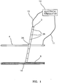
- FIGS. 1-5 A preferred embodiment of the invention is illustrated in FIGS. 1-5 , wherein FIG. 1 illustrates the electrode probe 2 locating the nerve 6 by electrically stimulating the nerve 6 and observing the muscle response.
- the electrical signal is generated by the electrical stimulator 12, e.g., a pulse generator. It is obvious that the electrode probe 2 could be a detector and electrical stimulator 12 could be a signal amplifier.
- the signal passes along electrode probe wire 10, along electrically insulated electrode probe 2 to conducting tip 14.
- Return electrode probe wire 11 preferably completes the electrical path by connecting between the skin 4 and electrical stimulator 12.
- Electrode probe 2 is electrically insulated along its entire length, except that the conducting tip 14 is not insulated, allowing the electrical signal to pass into the living tissue. Visual observation of the contracting muscle indicates when the conducting tip 14 is located next to nerve 6.
- Location marks 28, that circumscribes electrode probe 2 provides a visual indication of the precise location of the nerve.
- electrode probe wire 10 is detached from the electrode probe 2 and an outer sheath 16, as illustrated in FIG. 2 , is slid over and along the electrode probe 2, to penetrate the living tissue.
- the outer sheath 16 is inserted until it aligns with depth indicator 29, a selected one of the location marks 28.
- the outer sheath 16 contains a sheath lead wire 20, which is electrically insulated along its length.
- the sheath lead wire 20 passes along the length of outer sheath 16, preferably on its inner diameter along the wall.
- the lead wire 20 terminates at the sheath electrode 18, which is preferably located on the end of the outer sheath 16 that contacts the nerve 6.
- the sheath electrode 18 preferably receives an electrical signal from the electrical stimulator 12 by a current that passes along sheath lead wire 20 to the sheath electrode 18.
- a return electrode is preferably attached to the skin 4 and the electrical circuit is completed by return electrode probe wire 11.
- the outer sheath 16 is inserted to align with an electrode location mark 28 such that the sheath electrode 18 is located near the nerve 6.
- the position of the sheath 16 is optimized by electrically pulsing the nerve 6 and observing the response of the associated muscle.
- electrode probe 2 is removed, the position of the outer sheath 16 is confirmed by electrically pulsing the nerve 6, as previously discussed.
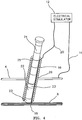
- FIG. 4 illustrates the outer sheath 16 with the microstimulator 22 being pushed into the outer sheath 16 with blunt-end push rod 24.
- the push rod 24 is inserted to a location mark 25 such that the microstimulator 22 is located at the end of outer sheath 16, near the nerve 6.
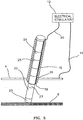
- the position of the microstimulator 22 can be verified by testing it before the outer sheath 16 is removed. If a problem is discovered, then the microstimulator 22 may be easily removed with the outer sheath 16. If no problem is discovered and if it is desired to implant the microstimulator 22, then the outer sheath 16 is removed, as illustrated in FIG. 5 , by holding the microstimulator 22 in position near the nerve 6 with the push rod 24 while the outer sheath 16 is removed.
- FIGS. 6- 9 An alternative embodiment of the invention is illustrated in FIGS. 6- 9 .
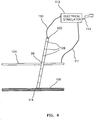
- FIG. 6 illustrates the electrode probe 102 locating the nerve 106 by electrically stimulating the nerve 106. The response of the associated muscle is observed.
- Electrode probe 102 is electrically insulated along its length, but conducting tip 114 is not insulated, allowing the electrical signal to pass into the living tissue.
- the location marks 128 that circumscribe electrode probe 102 provide a precise location of the nerve depth.
- the electrical signal is generated by the electrical stimulator 112.
- the electrical stimulator 112 may be hand-operated or it may be operated by a foot-control lever 113 that is moved by the foot of the surgeon or an assistant.
- the signal passes along electrode probe wire 110, along electrically insulated electrode probe 102 to conducting tip 114.
- Return electrode probe wire 111 preferably completes the electrical path by connecting between the skin 4 and electrical stimulator 112.
- electrode probe wire 110 is detached from the electrode probe 102 (see FIG. 6 ) and sheath lead wire 120 is attached to sheath electrode 118 (see FIG. 7 ). Then, an inner sheath 108 and outer sheath 116 are slid along the electrode probe 102, as shown in FIG. 7 .
- the inner sheath 108 is sharp and enters the skin 104 and other living tissue at insertion point 26, enlarging the hole for the implantation, until the top of inner sheath 108 aligns with depth indicator 129 on electrode probe 102 (a selected one of the location marks 128), thereby indicating that the tip of the inner sheath 108 is aligned with and is next to the nerve 106.
- the electrode probe 102 is then removed from the inner sheath 108.
- the inner sheath 108 is removed from the outer sheath 116.
- the location of the outer sheath 116, with respect to the nerve 106, is determined by passing an electrical signal from the electrical stimulator 112 along electrode probe wire 120, which is preferably embedded in the interior wall of the outer sheath 116, as illustrated in FIG. 7 .
- the electrode probe wire 120 may pass along the outside of outer sheath 116 or it may be embedded in the wall of outer sheath 116.
- Outer sheath 116 is preferably electrically insulated or is comprised of a nonconductive material, such as plastic, to ensure that the electrical pulsing signals that are used to locate the nerve pass into the living tissue and not into the outer sheath 116.
- the outer sheath 116 can no longer be readily relocated because the outer sheath 116 is not designed to penetrate living tissue.
- Saline solution is injected into outer sheath 116 to ensure that electrical conductivity is established when the microstimulator 122 is placed in outer sheath 116 (see FIG. 8 ).
- Outer sheath 116 contains a plurality of holes 117 that are located to facilitate electrical contact between the microstimulator 122 and the living tissue.
- the microstimulator 122 preferably has an axial dimension of less than 60 mm and a lateral dimension of less than 6 mm.
- the microstimulator 122 has microstimulator electrodes 123 located on each end.
- the sheath electrode 118 may be electrically pulsed to ensure that the location of outer sheath 116 has not changed significantly, relative to the nerve 106, while the microstimulator 122 is placed in the outer sheath 116.
- FIG. 8 illustrates the microstimulator 122 as it has been placed inside outer sheath 116 and urged toward nerve 106 by blunt-end push rod 124.
- Blunt-end push rod 124 contains push rod location marks 125, which indicate the position of the microstimulator 122 during insertion.
- Push rod depth indicator 130 (a selected one of the location marks 125), which indicates when the microstimulator has arrived at the end of outer sheath 116, and is therefore near nerve 106.
- the microstimulator may be urged along outer sheath 116 by the electrode probe 102 or by inner sheath 108. It is beneficial that any alternative push rod have location marks to indicate when the microstimulator 122 has arrived at the end of the outer sheath 116.
- the microstimulator 122 Before the microstimulator 122 is ejected from the outer sheath 116, its position may be confirmed by stimulation of the sheath electrode 118. Furthermore, the function of the microstimulator 122 may be checked by causing stimulation pulses to be emitted from the electrodes of the microstimulator.
- the microstimulator 122 is ejected from the outer sheath 116, FIG. 9 , by holding the push rod 124 in place as the outer sheath 116 is withdrawn away from the nerve 106 and out of the living tissue at insertion point 26.
- this apparatus implants the microstimulator 122 a distance from the nerve 106 that is approximately equal to the distance from the sharp tip of the inner sheath 108 to the tip of outer sheath 116.
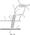
- FIG. 10 provides a side view of the electrode probe 2, which is used to initially locate the nerve 6 (and/or muscle tissue) by means of inserting the probe 2 into the living tissue, preferably at an angle to the skin 4 through an insertion point 26 in the skin 4 and into the living tissue.
- the electrode probe 2 is a sharp device that is electrically insulated along its length but that is not electrically insulated at its conducting tip 14.
- the electrode probe 2 is used to electrically stimulate the living tissue near the tip 14, thereby locating the desired nerve 6 by eliciting a specific response, such as contraction of a nearby muscle. It is understood that this approach can equally well be used to stimulate muscle tissue.
- the electrode probe 2 is attached by electrode probe wire 10 to an electrical stimulator 12, which can be pulsed manually to locate the nerve 6.
- the electrical path is completed by return electrode probe wire 11, that is preferably attached to skin 4.
- the electrical stimulator 12 be controlled by foot control 13, although it may be controlled by a hand control in the alternative.
- the electrode probe 2 location with respect to the nerve 6 and/or the muscle tissue is determined by observing the muscle response when the electrode probe 2 is electrically stimulated.
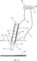
- the inner sheath 8 is slid along the electrode probe 2 to enlarge the opening in the tissue (see FIG. 10 ).
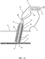
- the inner sheath 8 and outer sheath 16 may be simultaneously slid along the pre-positioned electrode probe 2 into the living tissue.
- the electrode probe 2 is held in close proximity to the nerve 6 while a cylindrically hollow outer sheath 16 is slid over the inner sheath 8.
- the inside diameter of inner sheath 8 has a diametral dimension that is preferably slightly larger than the outer diameter of electrode probe 2, e.g., by 5% to 20%, while the outside diameter of inner sheath 8 preferably is approximately equal to the outside diameter of microstimulator 22, e.g., within about 5% (see FIG. 13 ).
- a thin electrically conductive sheath lead wire 20, having a diameter of about one-thousandth of an inch, is located in the wall of outer sheath 16 connecting the sheath electrode 18 and the electrical stimulator 12.
- the sheath electrode 18 is located on the end of the outer sheath 16 that is nearest the nerve 6.
- This device offers the additional improved feature that both the outer sheath 16 and the inner sheath 8 are near the nerve 6, thus allowing the ultimate position of the implanted microdevice to be near the nerve 6.
- the electrode probe 2 and inner sheath 8 are removed from the living tissue while the position of the outer sheath 16 is maintained next to the nerve 6 by electrically pulsing the nerve 6 with a current from sheath electrode 18 and observing the response of the muscle associated with the nerve 6.
- both the inner sheath 8 and the outer sheath 16 must be non-conductors or must be electrically insulated from the living tissue. Accordingly, in a preferred embodiment, the inner sheath 8 and the outer sheath 16 are made of plastic.
- the sheath lead wire 20 may be located in alternative locations in or along the wall of the outer sheath 16.
- the sheath lead wire 20 may be located in the wall, which is preferred, or along the outside of the hollow outer sheath 16, or inside the outer sheath 16, e.g., in a groove.
- the sheath lead wire 20 can then be used to conduct an electrical signal to stimulate the nerve 6 and to confirm the position of the outer sheath 16 relative to the nerve 6.
- the outer sheath 16 Prior to insertion of the microstimulator 22, the outer sheath 16 may be flushed with saline solution. Holes 17 are located in the outer sheath at locations to ensure good electrical contact between the microstimulator 22, after it is inserted into the outer sheath 16, and the living tissue.
- a microstimulator 22 (see FIG. 13 ) is typically a small tubular device that contains an electronic package and communication means, for modifying or affecting a body parameter, when it is located near a nerve 6 or muscle to be stimulated.
- the microstimulator 22 has microstimulator electrodes 23 located on each end.
- FIG. 13 illustrates the microstimulator 22 being inserted into the outer sheath 16 using the blunt-end push rod 24.
- the microstimulator can be inserted into the outer sheath 16 by using the electrode probe 2 or inner sheath 8.
- the blunt-end push rod 24 has location mark 28 that circumscribes the push rod 24 such that the location of the microstimulator 22 in the outer sheath 16 can be ascertained by reference to the location mark 28.
- the microstimulator 22 is activated and powered via an externally provided RF signal and the muscle that responded before is observed to see if it is still responding when stimulated by the microstimulator 22.
- the microstimulator 22 may be activated by an RF signal or powered by means other than via an RF signal, such as by an internal battery. If the muscle is responding properly, the outer sheath 16 is pulled back while restraining the microstimulator 22 with the blunt-end push rod 24 (see FIG. 13 ).
- the microstimulator 22 is free of the outer sheath 16 and both the outer sheath 16 and blunt-end push rod 24 are removed from the living tissue.
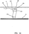
- the microstimulator 22 remains in position next to the nerve 6 and at the base of insertion point 26, as illustrated in FIG. 14 , after the outer sheath 16 and the blunt-end push rod 24 have been removed.
- the microstimulator 22 (see FIG. 13 ) contains removal loop 30, e.g., an eyelet, on the end nearest the skin 4 to facilitate attachment of removal string 32 to the microstimulator 22.
- the removal string 32 may be left in the living tissue near the insertion point 26 (see FIG. 14 ) or it may be left outside the living tissue.
- the removal string may be used to locate and/or to remove the microstimulator by pulling on it. This technique is effective for a few days post-surgery to remove the microstimulator 22 without risking further damage or trauma to the implant area, until the tissue begins to heal and adheres to the microstimulator.
- biocompatible fabric tube 100 An alternative embodiment to the removal system using the removal string 32 connected to the removal loop 30 on the microstimulator 22 (see FIGS. 13 and 14 ) is to place the microstimulator 22 in a porous, non-soluble, biocompatible fabric tube 100 (see FIG. 15 ).
- a preferred material for biocompatible fabric tube 100 is a silk tube, which is essentially a "sock" or closed end tube.
- Silk is a preferred material because it is biocompatible and does not bond readily to the living tissue.
- any closely woven material made of non-soluble material may be used.
- Alternatives include dialysis membrane materials.
- the ideal material is porous to allow solute materials to penetrate and flood the microstimulator surfaces for optimum electrical contact, however the structure of the materials must be so fine that the body's connective tissue cannot penetrate and lock the fabric tube 100 into place. Should the microstimulator 22 need to be removed, then the end of the fabric tube 100 is located either protruding from the skin 4 or implanted beneath the skin 4 near insertion point 26, and slowly withdrawn from the living tissue with the microstimulator 22 inside.
- FIGS. 16-18 A further embodiment of an insertion system for placing a microstimulator or microsensor into living tissue is presented in FIGS. 16-18 .
- the electrically insulated electrode probe 202 is first inserted in the living tissue through the skin 204 at insertion point 26 in order to locate a nerve 206 by electrically stimulating the nerve 206 and visually observing the muscle response.
- the electrical signal is generated by an electrical stimulator 212 and the signal passes along a wire (not illustrated) to the electrode probe 202 and to the exposed electrically conductive tip 214 of the electrode probe 202.
- the circuit is completed by return electrode probe wire 211 that is preferably attached to the skin 204.
- the insulated wire 210 is removed from the electrode probe 202 after the probe 202 has located the nerve 206.
- the dilator outer sheath 216 is inserted over electrode probe 202 and into the living tissue until the aperture tip 230 of the dilator outer sheath 216 is approximately aligned with the conducting tip 214 of the electrode probe 202.
- the dilator outer sheath 216 has a sharp end to facilitate insertion into the living tissue. The sharp end forms aperture 230.
- the proper alignment is achieved by visually aligning the dilator outer sheath 216 with the location mark 228.
- the electrode probe 202 is removed and the location, relative to the nerve 206, of the dilator outer sheath 216 is confirmed by passing an electrical signal from the electrical stimulator 212 along the electrically insulated wire 210, which in a preferred embodiment extends along the inside wall of the dilator outer sheath 216.
- the insulated wire 210 terminates in sheath electrode 218, which is located near aperture 230.
- the circuit is completed by return electrode probe wire 211 that is preferably attached to the skin 204.
- the wire 210 may be located along the outside wall or may be replaced with a conductive path along the outside wall of the dilator outer sheath 216 or along the inside wall of the dilator outer sheath 216.
- the nerve 206 is pulsed with an electrical signal from the sheath electrode 218 and the response of the muscle is observed.
- the dilator outer sheath 216 is electrically insulated to avoid conduction of electricity into the dilator outer sheath 216 and away from nerve 206.
- the dilator outer sheath 216 is preferably comprised of plastic.
- Dilator outer sheath 216 preferably contains a plurality of holes 217 that pass through the wall near the aperture 230 (see FIG. 17 ). The holes 217 are preferably located to provide an electrically conductive path between the living tissue and the microstimulator 222.
- FIG. 17 illustrates the dilator outer sheath 216 with the microstimulator 222 inserted therein and next to the aperture 230 that is next to the nerve 206.
- the microstimulator 222 is shown inserted part way along the inside of the dilator outer sheath 216 in FIG. 17 .
- the microstimulator 222 has microstimulator electrodes 223 located on each end. The microstimulator 222 will be inserted until the nerve-end of the microstimulator 222 is approximately even with the aperture 230 formed by dilator outer sheath 216. When the microstimulator 222 is fully inserted in dilator outer sheath 216, the microstimulator 222 is near nerve 206.
- the inside diameter of the dilator outer sheath 216 is preferably larger than the outside diameter of the microstimulator 222, e.g., by 5% to 20%, allowing the microstimulator 222 to pass along the length of the dilator outer sheath 216 with moderate pressure from the blunt-end push rod 224.
- the microstimulator 222 is positioned by using the blunt-end push rod 224, although the electrode probe 202 or another comparable probe with location marks can be used.
- the dilator outer sheath 216 may move after electrode probe 202 is removed and during the insertion of microstimulator 222, the location of the dilator outer sheath 216, and more particularly the aperture 230, next to the nerve 206 is verified by preferably pulsing nerve 206 with a current from conducting tip 218 and observing the response of the muscle.
- the function of the microstimulator 222 is confirmed by checking its electrical functions. If there is a problem with the microstimulator 222 or if the dilator outer sheath 216 moved and is no longer located next to the nerve 206, then the microstimulator 222 may be removed by withdrawing the dilator outer sheath 216 from the living tissue.
- the dilator outer sheath 216 is removed from the living tissue by holding the microstimulator 222 in place with the blunt-end push rod 224 and moving the dilator outer sheath 216 along the push rod 224 and out of the living tissue (see FIG. 18 ).
- Aperture 230 enlarges as microstimulator 222 is forced through the aperture.
- the microstimulator 222 shown in FIG. 18 , has been partially ejected from dilator outer sheath 216.
- the aperture 230 expandably conforms to the outside diameter of microstimulator 222 during the ejection process.
- the dilator outer sheath 216 is comprised of an electrical insulator, such as plastic, that conforms to allow ejection of the microstimulator 222.
- the microstimulator 222 is completely ejected by removing the dilator outer sheath 216 from the living tissue and leaving the microstimulator 222 in place next to the nerve 206.
- Placement of a microstimulator 322 in living tissue may be facilitated by using the implantation tool 300 of FIG. 19 .
- This implantation tool 300 enables one-handed placement of a microstimulator 322 near a nerve (not illustrated).
- the procedure begins with electrode probe 302 being used to locate the desired nerve by using electrical stimulation, as previously described.
- Electrode probe 302 is electrically insulated along its length to eliminate electrical shorts and is electrically conductive at its tip to pass an electrical signal to the stimulating site near the nerve.
- the implantation tool 300 is then slid over electrode probe 302. The electrode probe 302 is held steady until the aperture 330 is next to the nerve, as determined by observing the mark 304 on the electrode probe 302.
- the electrode probe 302 is removed from the implantation tool 300 and the position of implantation tool 300 relative to the nerve (not illustrated) is determined by observing the muscle response when the nerve is stimulated by pulsing the electrical stimulator 312 (see FIG. 20 ).
- the electrical signal passes along sheath electrode wire 310, which passes down the length of implantation tool 300 along outer sheath 316 and to sheath electrode 318, which is located at the end of the implantation tool 300, next to the nerve being stimulated.
- the electrical stimulator 312 is preferably controlled by a foot control.
- Saline is preferably injected into the implantation tool 300.
- the saline facilitates obtaining a good electrical connection between the nerve, living tissue, and the microstimulator 322 which is about to be implanted.
- the microstimulator 322 has microstimulator electrodes 323 located on each end.
- the plunger 360 is withdrawn from the implantation tool 300 (see FIG. 20 ) by moving ratcheting lever 350 with respect to handle 348, until the microstimulator 322 is moved into ejection position by ejection spring 306.
- the plunger 360 is then moved into the implantation tool 300 by reversing the direction set switch (not illustrated) and then moving ratcheting lever 350 with respect to handle 348.
- plunger 360 is moved to a predetermined position, as indicated by a mark 308 on the plunger 360, then the microstimulator 322 is next to the aperture 330, as illustrated in FIG. 21 .
- the outer sheath 316 and the plunger 360 are made of an electrically non-conductive material, such as plastic.
- the outer sheath 316 and plunger 360 must be insulated or must be non-conductors to ensure that the electrical pulsing signals that are used to locate the nerve are not electrically shorted.
- the holes 317 that are preferably located near the tip of the implantation tool 300 nearest the nerve, pass through the wall of the outer sheath 316.
- the holes 317 are located to correspond with the microstimulator 322 when it is ready to be ejected from the implantation tool 300, as illustrated in FIG. 21 , to enable electrical contact between the microstimulator 322 and the living tissue.
- the electrical functions of the microstimulator 322 are preferably verified while it is retained in the outer sheath 316, near the nerve (see FIG. 21 ).
- the microstimulator 322 is ejected by continuing to move ratcheting lever 350 to force the microstimulator 322 through the aperture 330 by means of the plunger 360.
- the implantation tool is slowly withdrawn from the living tissue and the microstimulator 322 is ejected to remain at the same relative position to the nerve.
- the outer sheath 316 is removable from the implantation tool 300 by disassembling disconnect 370. This allows the outer sheath 316 portion of the implantation tool 300 to be removed and discarded or cleaned separately from the rest of the tool 300.
- FIG. 22 depicts an alternative embodiment of the invention wherein there is a ring electrode 418 that is attached circumferentially at the sharpened tip of outer sheath 416 that is nearest the nerve 406.
- the outer sheath 416 passes through the skin 404 at the insertion point 426.
- the outer sheath 416 contains holes 417 which are located in the wall of the outer sheath 416 to facilitate electrical contact between the microstimulator (not shown) and the living tissue during insertion of the microstimulator in the tissue, but before the microstimulator has been ejected from the outer sheath 416.
- An electrical signal is generated by the electrical stimulator 412 that passes along sheath lead wire 420 to ring electrode 418.
- Ring electrode 418 is a conductive material that may be plated, deposited, mechanically bonded, or attached by any of the known processes for making a conductor that is integrally bonded to or a part of the sharpened tip of outer sheath 416.
- the sharpened tip end i.e., inserted end
- the distal end of the outer sheath 416 while the opposite end of the outer sheath 416 is referred to as the proximal end.
- FIG. 22 additionally depicts an alternative embodiment for a ring return electrode, wherein the ring return electrode 422 is located circumferentially around the outside of sheath 416.
- the ring return electrode 422 preferably acts as the cathode return element and completes the electrical circuit via the return electrode probe wire 411, which in turn connects to the electrical stimulator 412.
- the ring return electrode 422 is preferably located between the sharpened tip or distal end (i.e., the inserted end) and the proximal end of the sheath 416.
- a benefit of utilizing the ring electrode 418 in conjunction with the ring return electrode 422 is that by locating ring return electrode 422 a distance from ring electrode 418 that approximates the distance between the electrodes on the microstimulator (not illustrated), the electrical resistivity that the microstimulator will encounter after being implanted in the living tissue can be measured before the microstimulator is ejected from the outer sheath 416. This allows a prediction of the battery life of the implanted microstimulator and gives the surgeon an opportunity to modify the implantation location, if the predicted life or performance of the microstimulator is not adequate.
- the following nonlimiting example sets forth an exemplary procedure for implantation of a miniature implantable stimulator or sensor, e.g., the BION ® that is available from Advanced Bionics Corporation, by using an embodiment of the present invention.
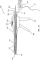
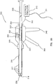
- a miniature implantable stimulator or sensor e.g., the BION ® that is available from Advanced Bionics Corporation
- MICROSTIMULATOR IMPLANTATION PROCEDURE MICROSTIMULATOR IMPLANTATION PROCEDURE, ANTERIOR APPROACH, FOR SLEEP APNEA
Landscapes
- Health & Medical Sciences (AREA)
- Neurology (AREA)
- Neurosurgery (AREA)
- Orthopedic Medicine & Surgery (AREA)
- Cardiology (AREA)
- Heart & Thoracic Surgery (AREA)
- Engineering & Computer Science (AREA)
- Biomedical Technology (AREA)
- Nuclear Medicine, Radiotherapy & Molecular Imaging (AREA)
- Radiology & Medical Imaging (AREA)
- Life Sciences & Earth Sciences (AREA)
- Animal Behavior & Ethology (AREA)
- General Health & Medical Sciences (AREA)
- Public Health (AREA)
- Veterinary Medicine (AREA)
- Electrotherapy Devices (AREA)
Claims (32)
- Einführsystem zur Platzierung einer medizinischen Vorrichtung (22, 122, 222, 322) nahe eines gewünschten neuromuskulären Pfades in lebendem Gewebe, wobei das Einführsystem Folgendes umfasst:einen Außenschaft (16, 116, 216, 316, 416), welcher konfiguriert ist, um die medizinische Vorrichtung aufzunehmen, dadurch gekennzeichnet, dass der Außenschaft einen elektrischen Leiter (20, 120, 210, 420) aufweist, der konfiguriert ist, um das lebende Gewebe zu kontaktieren und einen elektrischen Strom an das lebende Gewebe zu leiten, um einen neuromuskulären Pfad zu stimulieren, um die Nähe des Außenschaftes zum neuromuskulären Pfad zu bestimmen, um den Außenschaft nahe eines neuromuskulären Pfades zu platzieren und so die Implantation der medizinischen Vorrichtung nahe dem neuromuskulären Pfad zu erleichtern.
- Einführsystem nach Anspruch 1, welches ferner einen elektrischen Stimulator (12, 112, 212, 312, 412) umfasst, der mit dem elektrischen Leiter elektrisch gekoppelt ist.
- Einführsystem nach Anspruch 1, worin der Außenschaft ein distales Ende aufweist, wobei das distale Ende geschärft ist.
- Einführsystem nach Anspruch 1, worin der Außenschaft ein proximales Ende und ein distales Ende aufweist und der Außenschaft eine Ringelektrode (418) an dem distalen Ende umfasst, die mit dem elektrischen Leiter gekoppelt ist, um das lebende Gewebe zu kontaktieren.
- Einführsystem nach Anspruch 4, welches zusätzlich eine Ring-Gegenelektrode (422) umfasst, die auf dem Außenschaft zwischen dem proximalen Ende und dem distalen Ende angeordnet ist, um einen elektrischen Rückführpfad auszubilden.
- Einführsystem nach Anspruch 1, worin der Außenschaft ein proximales Ende und ein distales Ende aufweist und der elektrische Leiter einen elektrisch isolierten Draht (20, 210) umfasst, der zwischen dem proximalen Ende und dem distalen Ende angeordnet ist.
- Einführsystem nach Anspruch 1, worin der Außenschaft zylindrisch geformt ist und einen Außendurchmesser und einen Innendurchmesser aufweist, welche eine Wand zwischen ihnen definieren, und worin der elektrische Leiter einen isolierten Draht (120) umfasst, der innerhalb der Wand des Außenschafts angeordnet ist.
- Einführsystem nach Anspruch 1, worin der Außenschaft zylindrisch geformt ist und einen Außendurchmesser und einen Innendurchmesser aufweist, welche eine Wand zwischen ihnen definieren, und worin der elektrische Leiter einen elektrischen Leiter (20) umfasst, der innerhalb der Wand des Außenschafts angeordnet ist.
- Einführsystem nach Anspruch 1, welches ferner Folgendes umfasst:einen Innenschaft (8, 108), welcher dazu fähig ist, die medizinische Vorrichtung durch den Außenschaft zu drücken, wobei der Außenschaft den Innenschaft umgibt.
- Einführsystem nach Anspruch 9, worin der Innenschaft ein distales Ende aufweist, wobei das distale Ende geschärft ist.
- Einführsystem nach Anspruch 1, worin die medizinische Vorrichtung eine implantierbare Mikrovorrichtung umfasst, wobei das System zur Platzierung der implantierbaren Mikrovorrichtung nahe eines neuromuskulären Pfades in lebendem Gewebe ausgelegt ist, wobei die implantierbare Mikrovorrichtung zur neuromuskulären Stimulation und zum Abfühlen nahe eines gewünschten neuromuskulären Pfades in lebendem Gewebe geeignet ist, wobei das System ferner Folgendes umfasst:einen Innenschaft (8, 108), welcher zum Eindringen in lebendes Gewebe geeignet ist, wobei der Innenschaft eine Hohlkanüle mit einem Außendurchmesser ist, der in etwa gleich einem Außendurchmesser der implantierbaren Mikrovorrichtung ist und entfernbar in den Außenschaft einführbar ist, sodass, wenn der Innenschaft in den Außenschaft eingeführt wird, der Innenschaft geeignet sein kann, um entfernbar in das lebende Gewebe eingeführt zu werden.
- Einführsystem nach Anspruch 11, welches ferner Folgendes umfasst:eine starre Elektrodensonde (2, 102), welche ein geschärftes Ende aufweist, wobei die Sonde entfernbar in den Innenschaft einführbar ist, undwobei die Elektrodensonde an dem geschärften Ende elektrisch leitfähig und geeignet ist, um gewünschtes lebendes Gewebe zu kontaktieren und elektrisch zu stimulieren.
- Einführsystem nach Anspruch 12, worin die Elektrodensonde mit einem Fußschalter (13, 113) gekoppelt ist und von diesem aktiviert wird.
- Einführsystem nach Anspruch 11, 12 oder 13, worin der Außenschaft im Wesentlichen zylindrisch geformt ist und einen Außendurchmesser und einen Innendurchmesser aufweist, welche eine Innenoberfläche und eine Außenoberfläche definieren, und worin der elektrische Leiter ein isolierter Draht (210) ist, der entlang der Innenoberfläche des Außenschafts angeordnet ist.
- Einführsystem nach Anspruch 11, 12 oder 13, worin der Außenschaft im Wesentlichen zylindrisch geformt ist und einen Außendurchmesser, welcher eine Außenoberfläche definiert, und einen Innendurchmesser aufweist, welcher eine Innenfläche definiert, und worin der elektrische Leiter ein isolierter Draht ist, welcher entlang der Außenoberfläche des Außenschafts angeordnet ist.
- Einführsystem nach Anspruch 11, 12 oder 13, worin der Außenschaft im Wesentlichen zylindrisch geformt ist und einen Außendurchmesser, welcher eine Außenoberfläche definiert, und einen Innendurchmesser aufweist, welcher eine Innenoberfläche definiert, und worin der elektrische Leiter ein isolierter Draht (120) ist, der innerhalb der Wand des Außenschafts angeordnet ist.
- Einführsystem nach Anspruch 11, 12 oder 13, worin der elektrische Leiter eine Ringelektrode (418) ist.
- Einführsystem nach Anspruch 11, 12 oder 13, worin ein Außenschaft im Wesentlichen zylindrisch geformt ist und einen Außendurchmesser, welcher eine Außenoberfläche definiert, sowie einen Innendurchmesser aufweist, welcher eine Innenoberfläche definiert, und worin eine Ring-Gegenelektrode (422) auf der Außenoberfläche des Außenschafts angeordnet ist, um einen elektrischen Rückführpfad auszubilden.
- Einführsystem nach Anspruch 11, 12 oder 13, worin der Außenschaft im Wesentlichen zylindrisch geformt ist und einen Außendurchmesser und einen Innendurchmesser aufweist, die eine Wand zwischen ihnen definieren, und worin der elektrischen Leiter (20) ein leitfähiger Pfad aus Metall ist, der in der Wand des Außenschafts angeordnet ist.
- Einführsystem nach einem der Ansprüche 11 bis 19, welches zusätzlich eine Schubstange (24, 124, 224) mit einem stumpfen Ende umfasst, die entfernbar in den Außenschaft einführbar ist und konfiguriert ist, um die Mikrovorrichtung durch den Außenschaft und in die Nähe des neuromuskulären Pfades zu schieben.
- Einführsystem nach einem der Ansprüche 11 bis 20, worin die implantierbare Mikrovorrichtung Folgendes umfasst:ein hermetisch versiegeltes Gehäuse;zumindest zwei freiliegende Elektroden (23, 123), um ein elektrisches Signal zwischen der Mikrovorrichtung und dem umgebenden Gewebe zu leiten;und elektronische Schaltkreismittel innerhalb des Gehäuses, um ein elektrisches Signal zu erzeugen oder zu empfangen.
- Einführsystem nach Anspruch 1, worin die medizinische Vorrichtung eine Mikrovorrichtung umfasst; wobei das System für die Platzierung der Mikrovorrichtung ausgelegt ist, um einen Körperparameter zu modifizieren oder zu beeinflussen, wenn die Mikrovorrichtung nahe eines gewünschten neuromuskulären Pfades in lebendem Gewebe angeordnet ist, wobei die Mikrovorrichtung im Wesentlichen zylindrisch geformt ist und einen Außendurchmesser aufweist, worin:der Außenschaft ein distales Ende aufweist, wobei das distale Ende scharf ist und ausziehbar ist, um zu erlauben, dass die Mikrovorrichtung durch dieses hindurch ausgeworfen wird, worin der Außenschaft eine im Wesentlichen zylindrisch geformte Hohlkanüle mit einem Innendurchmesser ist, der in etwa gleich dem Außendurchmesser der Mikrovorrichtung ist, wobei der Außenschaft dimensioniert ist, um die Mikrovorrichtung vorübergehend unterzubringen, worin der Außenschaft entfernbar in das lebende Gewebe einführbar ist; undder Außenschaft eine Elektrode (18, 118, 218, 318, 418) umfasst, die auf dem distalen Ende angeordnet und konfiguriert ist, das lebende Gewebe zu kontaktieren, und die mit dem elektrischen Leiter elektrisch verbunden ist, um ein elektrisches Signal zwischen der Einführvorrichtung und dem lebenden Gewebe zu leiten, um zu bestätigen, dass das distale Ende nahe dem neuromuskulären Pfad geeignet positioniert ist.
- Einführsystem nach Anspruch 22, worin der Außenschaft einen Außendurchmesser aufweist, welcher eine Außenoberfläche definiert, wobei die Elektrode eine Ringelektrode (418) auf der Außenoberfläche umfasst, die mit dem Mittel zur elektrischen Signalleitung gekoppelt ist.
- Einführsystem nach Anspruch 23, worin eine Ring-Gegenelektrode (422) auf der Außenoberfläche des Außenschafts angeordnet ist, um einen elektrischen Rückführpfad auszubilden.
- Einführsystem nach Anspruch 1, worin die medizinische Vorrichtung eine Mikrovorrichtung umfasst, wobei das System zur Platzierung der Mikrovorrichtung ausgelegt ist, um einen Körperparameter zu modifizieren oder zu beeinflussen, wenn die Mikrovorrichtung nahe einem gewünschten neuromuskulären Pfad in lebendem Gewebe angeordnet ist, wobei die Mikrovorrichtung im Wesentlichen zylindrisch geformt ist und einen Außendurchmesser aufweist, worin:der Außenschaft im Wesentlichen zylindrisch geformt ist und einen Innendurchmesser aufweist, der ein hohles Zentrum definiert, wobei der Innendurchmesser geringfügig größer ist als der Außendurchmesser der Mikrovorrichtung, die das hohle Zentrum durchlaufen soll, worin der Außenschaft ein distales Ende aufweist, das geschärft ist, um lebendes Gewebe zu durchdringen, und ferner eine Öffnung aufweist, die durch das distale Ende hindurchgeht;und welches ferner Folgendes umfasst:ein Außenschaft-Verbindungsmittel zum Befestigen an dem Einführsystem;einen Stößel (360), der entfernbar in das hohle Zentrum des Außenschafts einführbar ist;einen Sperrhebel (350), welcher betätigbar ist, um zu bewirken, dass der Stößel in dem hohlen Zentrum hin zum distalen Ende gleitet; sowieMittel zum Leiten eines elektrischen Signals entlang des Außenschafts zu einer Schaftelektrode, die an dem distalen Ende angeordnet ist.
- Einführsystem nach Anspruch 25, worin die Schaftelektrode eine Ringelektrode umfasst, die mit Mitteln zum Leiten eines elektrischen Signals gekoppelt ist.
- Einführsystem nach Anspruch 25 oder 26, worin eine Ring-Gegenelektrode auf dem Außenschaft angeordnet ist, um einen elektrischen Rückführpfad auszubilden.
- Einführsystem nach Anspruch 25, 26 oder 27, welches zusätzlich Mittel zum Platzieren der Mikrovorrichtung in dem hohlen Zentrum des Außenschafts umfasst, um die Platzierung der Mikrovorrichtung an dem distalen Ende des Außenschafts zu ermöglichen.
- Einführsystem nach einem der Ansprüche 25-28, welches ferner Folgendes umfasst:eine längliche Elektrodensonde (302) mit einem Außendurchmesser,wobei der Stößel einen im Wesentlichen zylindrischen Querschnitt aufweist, wobei der Stößel eine Länge und einen Innendurchmesser aufweist, welche einen Kanal definieren, der sich longitudinal entlang dessen Länge erstreckt, wobei der Innendurchmesser der Sonde geringfügig größer als der Außendurchmesser der Elektrodensonde ist; und worindie Elektrodensonde entfernbar in den Stößel einführbar ist.
- Einführsystem nach Anspruch 1, worin die medizinische Vorrichtung eine implantierbare medizinische Vorrichtung umfasst, worin der Außenschaft eine ausziehbare, geschärfte Spitze aufweist, um das lebende Gewebe zu durchdringen, wobei die Spitze ausziehbar ist, um zu ermöglichen, dass die implantierbare medizinische Vorrichtung entfernbar aus dem Außenschaft ausgeworfen wird.
- Einführsystem nach Anspruch 1, worin die medizinische Vorrichtung eine implantierbare medizinische Vorrichtung umfasst, wobei das System zur Platzierung der implantierbaren medizinischen Vorrichtung nahe einem neuromuskulären Pfad in lebendem Gewebe ausgelegt ist, worin die implantierbare medizinische Vorrichtung eine axiale Dimension von weniger als 60 mm und eine laterale Dimension von weniger als 6 mm aufweist, worin:der Außenschaft konfiguriert ist, um die implantierbare medizinische Vorrichtung zumindest teilweise zu enthalten, worin der Außenschaft einen Außendurchmesser und einen Innendurchmesser aufweist, die eine Wand definieren, wobei die Wand zumindest ein Durchgangsloch in der Wand definiert, wobei das Loch angeordnet ist, um einen elektrischen Kontakt zwischen der implantierbaren medizinischen Vorrichtung, während diese in dem Außenschaft enthalten ist, und dem lebenden Gewebe zu ermöglichen.
- Einführsystem nach Anspruch 31, worin die medizinische Vorrichtung ein Mikrostimulator oder ein Mikrosensor ist.
Applications Claiming Priority (3)
| Application Number | Priority Date | Filing Date | Title |
|---|---|---|---|
| US116619 | 2002-04-04 | ||
| US10/116,619 US6829508B2 (en) | 2001-10-19 | 2002-04-04 | Electrically sensing and stimulating system for placement of a nerve stimulator or sensor |
| PCT/US2002/033018 WO2003084398A1 (en) | 2002-04-04 | 2002-10-16 | Electrically sensing and stimulating system for placement of a nerve stimulator or sensor |
Publications (3)
| Publication Number | Publication Date |
|---|---|
| EP1494583A1 EP1494583A1 (de) | 2005-01-12 |
| EP1494583A4 EP1494583A4 (de) | 2009-12-16 |
| EP1494583B1 true EP1494583B1 (de) | 2016-12-07 |
Family
ID=28789844
Family Applications (1)
| Application Number | Title | Priority Date | Filing Date |
|---|---|---|---|
| EP02786417.2A Expired - Lifetime EP1494583B1 (de) | 2002-04-04 | 2002-10-16 | Elektrisches mess- und stimulationssystem zur platzierung eines nervenstimulators oder sensors |
Country Status (4)
| Country | Link |
|---|---|
| US (1) | US6829508B2 (de) |
| EP (1) | EP1494583B1 (de) |
| AU (1) | AU2002351500A1 (de) |
| WO (1) | WO2003084398A1 (de) |
Families Citing this family (163)
| Publication number | Priority date | Publication date | Assignee | Title |
|---|---|---|---|---|
| US7470236B1 (en) | 1999-11-24 | 2008-12-30 | Nuvasive, Inc. | Electromyography system |
| US7033326B1 (en) | 2000-12-29 | 2006-04-25 | Advanced Bionics Corporation | Systems and methods of implanting a lead for brain stimulation |
| WO2003005887A2 (en) | 2001-07-11 | 2003-01-23 | Nuvasive, Inc. | System and methods for determining nerve proximity, direction, and pathology during surgery |
| US7974693B2 (en) * | 2001-08-31 | 2011-07-05 | Bio Control Medical (B.C.M.) Ltd. | Techniques for applying, configuring, and coordinating nerve fiber stimulation |
| JP2005503857A (ja) * | 2001-09-25 | 2005-02-10 | ヌバシブ, インコーポレイテッド | 外科処置手順および外科的診断を実施するためのシステムおよび方法 |
| US7664544B2 (en) | 2002-10-30 | 2010-02-16 | Nuvasive, Inc. | System and methods for performing percutaneous pedicle integrity assessments |
| US7653438B2 (en) * | 2002-04-08 | 2010-01-26 | Ardian, Inc. | Methods and apparatus for renal neuromodulation |
| US7582058B1 (en) | 2002-06-26 | 2009-09-01 | Nuvasive, Inc. | Surgical access system and related methods |
| US8137284B2 (en) | 2002-10-08 | 2012-03-20 | Nuvasive, Inc. | Surgical access system and related methods |
| US8880192B2 (en) | 2012-04-02 | 2014-11-04 | Bio Control Medical (B.C.M.) Ltd. | Electrode cuffs |
| US7691057B2 (en) | 2003-01-16 | 2010-04-06 | Nuvasive, Inc. | Surgical access system and related methods |
| US7190051B2 (en) * | 2003-01-17 | 2007-03-13 | Second Sight Medical Products, Inc. | Chip level hermetic and biocompatible electronics package using SOI wafers |
| US7819801B2 (en) | 2003-02-27 | 2010-10-26 | Nuvasive, Inc. | Surgical access system and related methods |
| WO2005013805A2 (en) * | 2003-08-05 | 2005-02-17 | Nuvasive, Inc. | Systemand methods for performing dynamic pedicle integrity assessments |
| US7905840B2 (en) | 2003-10-17 | 2011-03-15 | Nuvasive, Inc. | Surgical access system and related methods |
| WO2005030318A1 (en) | 2003-09-25 | 2005-04-07 | Nuvasive, Inc. | Surgical access system and related methods |
| GB2407272B (en) * | 2003-10-20 | 2008-08-20 | Teodor Goroszeniuk | Improvements in and relating to peripheral neurostimulation |
| CA2553901C (en) | 2004-01-22 | 2015-01-20 | Rehabtronics Inc. | Method of routing electrical current to bodily tissues via implanted passive conductors |
| WO2005096979A1 (en) | 2004-04-01 | 2005-10-20 | The General Hospital Corporation | Method and apparatus for dermatological treatment and tissue reshaping |
| US7245972B2 (en) * | 2004-04-29 | 2007-07-17 | Alfred E. Mann Foundation For Scientific Research | Electrical treatment to treat shoulder subluxation |
| US9622732B2 (en) | 2004-10-08 | 2017-04-18 | Nuvasive, Inc. | Surgical access system and related methods |
| US7542804B2 (en) | 2004-12-03 | 2009-06-02 | Alfred E. Mann Foundation For Scientific Research | Neuromuscular stimulation to avoid pulmonary embolisms |
| US7536227B1 (en) * | 2005-01-26 | 2009-05-19 | Pacesetter, Inc. | Shielded electrode for nerve sensing |
| US7294108B1 (en) * | 2005-01-27 | 2007-11-13 | Pacesetter, Inc. | Cardiac event microrecorder and method for implanting same |
| US20110054346A1 (en) * | 2005-03-01 | 2011-03-03 | Checkpoint Surgical, Llc | Systems and methods for Intra-operative semi-quantitative threshold neural response testing related applications |
| US7878981B2 (en) | 2005-03-01 | 2011-02-01 | Checkpoint Surgical, Llc | Systems and methods for intra-operative stimulation |
| US20110060242A1 (en) * | 2005-03-01 | 2011-03-10 | Checkpoint Surgical, Llc | Systems and methods for intra-operative stimulation within a surgical field |
| US20110060243A1 (en) * | 2005-03-01 | 2011-03-10 | Checkpoint Surgical, Llc | Systems and methods for intra-operative regional neural stimulation |
| US10154792B2 (en) | 2005-03-01 | 2018-12-18 | Checkpoint Surgical, Inc. | Stimulation device adapter |
| US7896815B2 (en) * | 2005-03-01 | 2011-03-01 | Checkpoint Surgical, Llc | Systems and methods for intra-operative stimulation |
| US20110060238A1 (en) * | 2005-03-01 | 2011-03-10 | Checkpoint Surgical, Llc | Systems and methods for intra-operative physiological functional stimulation |
| US20060200219A1 (en) * | 2005-03-01 | 2006-09-07 | Ndi Medical, Llc | Systems and methods for differentiating and/or identifying tissue regions innervated by targeted nerves for diagnostic and/or therapeutic purposes |
| US20060253181A1 (en) * | 2005-05-05 | 2006-11-09 | Alfred E. Mann Foundation For Scientific Research | Lead insertion tool |
| US7644714B2 (en) | 2005-05-27 | 2010-01-12 | Apnex Medical, Inc. | Devices and methods for treating sleep disorders |
| US20060276720A1 (en) * | 2005-06-03 | 2006-12-07 | Mcginnis William C | Method of using dermatomal somatosensory evoked potentials in real-time for surgical and clinical management |
| JP5249024B2 (ja) | 2005-06-28 | 2013-07-31 | バイオネス インコーポレイテッド | 電流を通す埋込み受動導体を使用するインプラント、システムおよび方法に対する改良 |
| US7684858B2 (en) * | 2005-09-21 | 2010-03-23 | Boston Scientific Neuromodulation Corporation | Methods and systems for placing an implanted stimulator for stimulating tissue |
| US8271094B1 (en) | 2005-09-30 | 2012-09-18 | Boston Scientific Neuromodulation Corporation | Devices with cannula and electrode lead for brain stimulation and methods of use and manufacture |
| US7805202B2 (en) * | 2005-09-30 | 2010-09-28 | Boston Scientific Neuromodulation Corporation | Implantable electrodes and insertion methods and tools |
| US8010209B2 (en) | 2005-10-14 | 2011-08-30 | Nanostim, Inc. | Delivery system for implantable biostimulator |
| US9168383B2 (en) | 2005-10-14 | 2015-10-27 | Pacesetter, Inc. | Leadless cardiac pacemaker with conducted communication |
| JP4774272B2 (ja) * | 2005-10-19 | 2011-09-14 | Hoya株式会社 | 内視鏡用高周波切開具 |
| US20070162051A1 (en) * | 2006-01-12 | 2007-07-12 | Alfred E. Mann Foundation For Scientific Research | Electrode implant tool |
| US7583999B2 (en) | 2006-07-31 | 2009-09-01 | Cranial Medical Systems, Inc. | Multi-channel connector for brain stimulation system |
| US8483820B2 (en) * | 2006-10-05 | 2013-07-09 | Bioness Inc. | System and method for percutaneous delivery of electrical stimulation to a target body tissue |
| US9205262B2 (en) | 2011-05-12 | 2015-12-08 | Cyberonics, Inc. | Devices and methods for sleep apnea treatment |
| US8855771B2 (en) | 2011-01-28 | 2014-10-07 | Cyberonics, Inc. | Screening devices and methods for obstructive sleep apnea therapy |
| DE202007019439U1 (de) | 2006-10-13 | 2012-09-12 | Apnex Medical, Inc. | Geräte, Systeme und Methoden zur Behandlung von obstruktiver Schalfapnoe |
| US9913982B2 (en) | 2011-01-28 | 2018-03-13 | Cyberonics, Inc. | Obstructive sleep apnea treatment devices, systems and methods |
| US9186511B2 (en) | 2006-10-13 | 2015-11-17 | Cyberonics, Inc. | Obstructive sleep apnea treatment devices, systems and methods |
| US9744354B2 (en) | 2008-12-31 | 2017-08-29 | Cyberonics, Inc. | Obstructive sleep apnea treatment devices, systems and methods |
| US20080097519A1 (en) * | 2006-10-20 | 2008-04-24 | Alfred E. Mann Foundation For Scientific Research | Medical device extraction tool |
| US7751880B1 (en) | 2007-02-12 | 2010-07-06 | Pacesetter, Inc. | Shielded electrode assembly for effective nerve sensing and stimulation |
| EP2142087B1 (de) | 2007-04-03 | 2016-06-29 | Nuvasive Inc. | Neurophysiologisches überwachungssystem |
| US8734466B2 (en) | 2007-04-25 | 2014-05-27 | Medtronic, Inc. | Method and apparatus for controlled insertion and withdrawal of electrodes |
| US9289270B2 (en) | 2007-04-24 | 2016-03-22 | Medtronic, Inc. | Method and apparatus for performing a navigated procedure |
| US8301226B2 (en) | 2007-04-24 | 2012-10-30 | Medtronic, Inc. | Method and apparatus for performing a navigated procedure |
| US8108025B2 (en) | 2007-04-24 | 2012-01-31 | Medtronic, Inc. | Flexible array for use in navigated surgery |
| US8311611B2 (en) | 2007-04-24 | 2012-11-13 | Medtronic, Inc. | Method for performing multiple registrations in a navigated procedure |
| US9561053B2 (en) | 2007-04-25 | 2017-02-07 | Medtronic, Inc. | Implant tool to facilitate medical device implantation |
| US9399130B2 (en) | 2007-04-25 | 2016-07-26 | Medtronic, Inc. | Cannula configured to deliver test stimulation |
| US8203560B2 (en) * | 2007-04-27 | 2012-06-19 | Sony Corporation | Method for predictively splitting procedurally generated particle data into screen-space boxes |
| US7765013B2 (en) * | 2007-06-04 | 2010-07-27 | Wisconsin Alumni Research Foundation | Nano- and micro-scale wireless stimulating probe |
| US7630771B2 (en) * | 2007-06-25 | 2009-12-08 | Microtransponder, Inc. | Grooved electrode and wireless microtransponder system |
| US20090043367A1 (en) * | 2007-08-09 | 2009-02-12 | Yitzhak Zilberman | Apparatus and methods for removing an electronic implant from a body |
| US8057486B2 (en) * | 2007-09-18 | 2011-11-15 | Bioness Inc. | Apparatus and method for inserting implants into the body |
| US20090259280A1 (en) * | 2007-10-15 | 2009-10-15 | Kevin Wilkin | Electrical stimulation lead with bioerodible anchors and anchor straps |
| US9089707B2 (en) | 2008-07-02 | 2015-07-28 | The Board Of Regents, The University Of Texas System | Systems, methods and devices for paired plasticity |
| US8457757B2 (en) * | 2007-11-26 | 2013-06-04 | Micro Transponder, Inc. | Implantable transponder systems and methods |
| US8364277B2 (en) * | 2008-01-10 | 2013-01-29 | Bioness Inc. | Methods and apparatus for implanting electronic implants within the body |
| US20090210040A1 (en) * | 2008-02-19 | 2009-08-20 | Ochoa Francisco | Variable length medical electrical stimulation lead |
| US20090281409A1 (en) * | 2008-05-06 | 2009-11-12 | Jeryle Walter | Reinforced medical device |
| US20090326602A1 (en) | 2008-06-27 | 2009-12-31 | Arkady Glukhovsky | Treatment of indications using electrical stimulation |
| US8494650B2 (en) * | 2008-08-07 | 2013-07-23 | Bioness, Inc. | Insertion tools and methods for an electrical stimulation implant |
| US7941227B2 (en) * | 2008-09-03 | 2011-05-10 | Boston Scientific Neuromodulation Corporation | Implantable electric stimulation system and methods of making and using |
| JP5547200B2 (ja) | 2008-10-01 | 2014-07-09 | インスパイア・メディカル・システムズ・インコーポレイテッド | 睡眠時無呼吸を治療する経静脈法 |
| JP5575789B2 (ja) | 2008-11-19 | 2014-08-20 | インスパイア・メディカル・システムズ・インコーポレイテッド | 睡眠呼吸障害の治療方法 |
| CA2750917A1 (en) | 2008-12-26 | 2010-07-01 | Scott Spann | Minimally-invasive retroperitoneal lateral approach for spinal surgery |
| US8685093B2 (en) | 2009-01-23 | 2014-04-01 | Warsaw Orthopedic, Inc. | Methods and systems for diagnosing, treating, or tracking spinal disorders |
| US8126736B2 (en) | 2009-01-23 | 2012-02-28 | Warsaw Orthopedic, Inc. | Methods and systems for diagnosing, treating, or tracking spinal disorders |
| US8527068B2 (en) | 2009-02-02 | 2013-09-03 | Nanostim, Inc. | Leadless cardiac pacemaker with secondary fixation capability |
| US8167640B2 (en) * | 2009-03-19 | 2012-05-01 | Bioness Inc. | Flexible connector for implantable electrical stimulation lead |
| US9486628B2 (en) | 2009-03-31 | 2016-11-08 | Inspire Medical Systems, Inc. | Percutaneous access for systems and methods of treating sleep apnea |
| AU2010284120B2 (en) | 2009-08-20 | 2016-06-02 | Alfred E. Mann Foundation For Scientific Research | Optimal narrowband interference removal for signals separated in time |
| US8788045B2 (en) | 2010-06-08 | 2014-07-22 | Bluewind Medical Ltd. | Tibial nerve stimulation |
| US9392953B1 (en) | 2010-09-17 | 2016-07-19 | Nuvasive, Inc. | Neurophysiologic monitoring |
| BR112013008190A2 (pt) * | 2010-10-04 | 2017-12-12 | Nervomatrix Ltd | eletrodo e aparato |
| US9060692B2 (en) | 2010-10-12 | 2015-06-23 | Pacesetter, Inc. | Temperature sensor for a leadless cardiac pacemaker |
| EP2627403A4 (de) | 2010-10-12 | 2014-03-26 | Nanostim Inc | Temperatursensor für einen bleifreien herzschrittmacher |
| US9020611B2 (en) | 2010-10-13 | 2015-04-28 | Pacesetter, Inc. | Leadless cardiac pacemaker with anti-unscrewing feature |
| US9457186B2 (en) | 2010-11-15 | 2016-10-04 | Bluewind Medical Ltd. | Bilateral feedback |
| US9186504B2 (en) | 2010-11-15 | 2015-11-17 | Rainbow Medical Ltd | Sleep apnea treatment |
| WO2012068247A1 (en) | 2010-11-16 | 2012-05-24 | The Board Of Trustees Of The Leland Stanford Junior University | Systems and methods for treatment of dry eye |
| US9821159B2 (en) | 2010-11-16 | 2017-11-21 | The Board Of Trustees Of The Leland Stanford Junior University | Stimulation devices and methods |
| EP2651494B1 (de) | 2010-12-13 | 2017-02-15 | Pacesetter, Inc. | Implantationskatheter |
| US9126032B2 (en) | 2010-12-13 | 2015-09-08 | Pacesetter, Inc. | Pacemaker retrieval systems and methods |
| CN103328040B (zh) | 2010-12-20 | 2016-09-14 | 内诺斯蒂姆股份有限公司 | 具有径向固定机构的无导线起搏器 |
| US9775982B2 (en) | 2010-12-29 | 2017-10-03 | Medtronic, Inc. | Implantable medical device fixation |
| US10112045B2 (en) | 2010-12-29 | 2018-10-30 | Medtronic, Inc. | Implantable medical device fixation |
| US8790406B1 (en) | 2011-04-01 | 2014-07-29 | William D. Smith | Systems and methods for performing spine surgery |
| WO2013028571A1 (en) | 2011-08-19 | 2013-02-28 | Lanx, Inc. | Surgical retractor system and methods of use |
| US9198765B1 (en) | 2011-10-31 | 2015-12-01 | Nuvasive, Inc. | Expandable spinal fusion implants and related methods |
| US9949651B2 (en) | 2011-11-01 | 2018-04-24 | DePuy Synthes Products, Inc. | Intraoperative neurophysiological monitoring system |
| WO2013067496A2 (en) | 2011-11-04 | 2013-05-10 | Nanostim, Inc. | Leadless cardiac pacemaker with integral battery and redundant welds |
| US9125573B2 (en) | 2011-12-29 | 2015-09-08 | St. Jude Medical, Atrial Fibrillation Division, Inc. | Electrically transparent introducer sheath |
| US20150018728A1 (en) | 2012-01-26 | 2015-01-15 | Bluewind Medical Ltd. | Wireless neurostimulators |
| US9854982B2 (en) | 2012-03-26 | 2018-01-02 | Medtronic, Inc. | Implantable medical device deployment within a vessel |
| US9339197B2 (en) | 2012-03-26 | 2016-05-17 | Medtronic, Inc. | Intravascular implantable medical device introduction |
| US9833625B2 (en) | 2012-03-26 | 2017-12-05 | Medtronic, Inc. | Implantable medical device delivery with inner and outer sheaths |
| US10485435B2 (en) | 2012-03-26 | 2019-11-26 | Medtronic, Inc. | Pass-through implantable medical device delivery catheter with removeable distal tip |
| US9220906B2 (en) | 2012-03-26 | 2015-12-29 | Medtronic, Inc. | Tethered implantable medical device deployment |
| US9717421B2 (en) | 2012-03-26 | 2017-08-01 | Medtronic, Inc. | Implantable medical device delivery catheter with tether |
| US8768488B2 (en) | 2012-05-25 | 2014-07-01 | Boston Scientific Neuromodulation Corporation | Systems and methods for electrically stimulating patient tissue on or around one or more bony structures |
| US8718790B2 (en) | 2012-05-25 | 2014-05-06 | Boston Scientific Neuromodulation Corporation | Systems and methods for providing electrical stimulation of multiple dorsal root ganglia with a single lead |
| AU2013266290B2 (en) * | 2012-05-25 | 2016-03-10 | Boston Scientific Neuromodulation Corporation | Percutaneous implantation of an electrical stimulation lead for stimulating dorsal root ganglion |
| US9919148B2 (en) | 2012-05-25 | 2018-03-20 | Boston Scientific Neuromodulation Corporation | Distally curved electrical stimulation lead and methods of making and using |
| US9802054B2 (en) | 2012-08-01 | 2017-10-31 | Pacesetter, Inc. | Biostimulator circuit with flying cell |
| US11877860B2 (en) | 2012-11-06 | 2024-01-23 | Nuvasive, Inc. | Systems and methods for performing neurophysiologic monitoring during spine surgery |
| US11259737B2 (en) | 2012-11-06 | 2022-03-01 | Nuvasive, Inc. | Systems and methods for performing neurophysiologic monitoring during spine surgery |
| US9757067B1 (en) | 2012-11-09 | 2017-09-12 | Nuvasive, Inc. | Systems and methods for performing neurophysiologic monitoring during spine surgery |
| WO2014087337A1 (en) | 2012-12-06 | 2014-06-12 | Bluewind Medical Ltd. | Delivery of implantable neurostimulators |
| US9826963B2 (en) | 2012-12-07 | 2017-11-28 | Medtronic, Inc. | Minimally invasive implantable neurostimulation system |
| US9757072B1 (en) | 2013-02-11 | 2017-09-12 | Nuvasive, Inc. | Waveform marker placement algorithm for use in neurophysiologic monitoring |
| US9265956B2 (en) | 2013-03-08 | 2016-02-23 | Oculeve, Inc. | Devices and methods for treating dry eye in animals |
| EP2967817B1 (de) | 2013-03-12 | 2021-03-10 | Oculeve, Inc. | Implantateinführungsvorrichtungen und -systeme |
| US9623220B2 (en) | 2013-03-14 | 2017-04-18 | The Alfred E. Mann Foundation For Scientific Research | Suture tracking dilators and related methods |
| NZ704579A (en) | 2013-04-19 | 2018-10-26 | Oculeve Inc | Nasal stimulation devices and methods |
| EP2996765B1 (de) | 2013-05-15 | 2019-06-26 | Boston Scientific Neuromodulation Corporation | Spitzenelektroden für elektrische stimulationssysteme |
| WO2015123360A1 (en) | 2014-02-11 | 2015-08-20 | Cyberonics, Inc. | Systems and methods of detecting and treating obstructive sleep apnea |
| WO2015130707A2 (en) | 2014-02-25 | 2015-09-03 | Oculeve, Inc. | Polymer formulations for nasolacrimal stimulation |
| CA2956176A1 (en) | 2014-07-25 | 2016-01-28 | Oculeve, Inc. | Stimulation patterns for treating dry eye |
| US10420480B1 (en) | 2014-09-16 | 2019-09-24 | Nuvasive, Inc. | Systems and methods for performing neurophysiologic monitoring |
| RU2707167C2 (ru) | 2014-10-22 | 2019-11-22 | Окулив, Инк. | Устройства для стимуляции и способы лечения болезни "сухого глаза" |
| WO2016065213A1 (en) | 2014-10-22 | 2016-04-28 | Oculeve, Inc. | Implantable nasal stimulator systems and methods |
| EP3209370A4 (de) | 2014-10-22 | 2018-05-30 | Oculeve, Inc. | Kontaktlinse zur erhöhung der tränenproduktion |
| US9764146B2 (en) | 2015-01-21 | 2017-09-19 | Bluewind Medical Ltd. | Extracorporeal implant controllers |
| US9597521B2 (en) | 2015-01-21 | 2017-03-21 | Bluewind Medical Ltd. | Transmitting coils for neurostimulation |
| US10004896B2 (en) | 2015-01-21 | 2018-06-26 | Bluewind Medical Ltd. | Anchors and implant devices |
| US9782589B2 (en) | 2015-06-10 | 2017-10-10 | Bluewind Medical Ltd. | Implantable electrostimulator for improving blood flow |
| US10105540B2 (en) | 2015-11-09 | 2018-10-23 | Bluewind Medical Ltd. | Optimization of application of current |
| US9713707B2 (en) | 2015-11-12 | 2017-07-25 | Bluewind Medical Ltd. | Inhibition of implant migration |
| US10328271B2 (en) | 2015-11-12 | 2019-06-25 | Medtronic, Inc. | Implantable electrical stimulator with deflecting tip lead |
| US10426958B2 (en) | 2015-12-04 | 2019-10-01 | Oculeve, Inc. | Intranasal stimulation for enhanced release of ocular mucins and other tear proteins |
| US10252048B2 (en) | 2016-02-19 | 2019-04-09 | Oculeve, Inc. | Nasal stimulation for rhinitis, nasal congestion, and ocular allergies |
| CA3022683A1 (en) | 2016-05-02 | 2017-11-09 | Oculeve, Inc. | Intranasal stimulation for treatment of meibomian gland disease and blepharitis |
| US10369354B2 (en) | 2016-05-17 | 2019-08-06 | Boston Scientific Neuromodulation Corporation | Systems and method for anchoring a lead for neurostimulation of a target anatomy |
| US10716935B2 (en) | 2016-11-04 | 2020-07-21 | Boston Scientific Neuromodulation Corporation | Electrical stimulation leads, systems and methods for stimulation of dorsal root ganglia |
| US10124178B2 (en) | 2016-11-23 | 2018-11-13 | Bluewind Medical Ltd. | Implant and delivery tool therefor |
| KR20190124698A (ko) | 2016-12-02 | 2019-11-05 | 오큘레브, 인크. | 건성안 예측 및 치료 권고를 위한 장치 및 방법 |
| US10709886B2 (en) | 2017-02-28 | 2020-07-14 | Boston Scientific Neuromodulation Corporation | Electrical stimulation leads and systems with elongate anchoring elements and methods of making and using |
| US10835739B2 (en) | 2017-03-24 | 2020-11-17 | Boston Scientific Neuromodulation Corporation | Electrical stimulation leads and systems with elongate anchoring elements and methods of making and using |
| US20180353764A1 (en) | 2017-06-13 | 2018-12-13 | Bluewind Medical Ltd. | Antenna configuration |
| US10874850B2 (en) | 2018-09-28 | 2020-12-29 | Medtronic, Inc. | Impedance-based verification for delivery of implantable medical devices |
| US11331475B2 (en) | 2019-05-07 | 2022-05-17 | Medtronic, Inc. | Tether assemblies for medical device delivery systems |
| US12151100B2 (en) | 2019-05-07 | 2024-11-26 | Medtronic, Inc. | Tether assemblies for medical device delivery systems |
| US11065461B2 (en) | 2019-07-08 | 2021-07-20 | Bioness Inc. | Implantable power adapter |
| CN114980958A (zh) * | 2019-11-27 | 2022-08-30 | 加尔瓦尼生物电子有限公司 | 用于神经接口的腹腔镜递送和部署的系统和方法 |
| US11426201B2 (en) * | 2020-01-24 | 2022-08-30 | Medtronic Xomed, Inc. | Treatment of obstructive sleep apnea (OSA) |
| US11246637B2 (en) | 2020-05-11 | 2022-02-15 | Alphatec Spine, Inc. | Stimulating targeting needle |
| US11400299B1 (en) | 2021-09-14 | 2022-08-02 | Rainbow Medical Ltd. | Flexible antenna for stimulator |
| WO2023150189A1 (en) * | 2022-02-02 | 2023-08-10 | Invicta Medical, Inc. | Delivery systems for injected neurostimulation devices, and associated systems and methods |
| CN115998381B (zh) * | 2022-03-03 | 2026-03-20 | 江苏畅医达医疗科技有限公司 | 一种电极植入工具 |
| CN116965893B (zh) * | 2023-09-22 | 2024-02-20 | 杭州启明医疗器械股份有限公司 | 一种植入物输送系统 |
Family Cites Families (11)
| Publication number | Priority date | Publication date | Assignee | Title |
|---|---|---|---|---|
| US5193539A (en) | 1991-12-18 | 1993-03-16 | Alfred E. Mann Foundation For Scientific Research | Implantable microstimulator |
| US5193540A (en) | 1991-12-18 | 1993-03-16 | Alfred E. Mann Foundation For Scientific Research | Structure and method of manufacture of an implantable microstimulator |
| US5775331A (en) | 1995-06-07 | 1998-07-07 | Uromed Corporation | Apparatus and method for locating a nerve |
| AU1057697A (en) | 1995-11-24 | 1997-06-11 | Advanced Bionics Corporation | System and method for conditioning pelvic musculature using an implanted microstimulator |
| US5779642A (en) | 1996-01-16 | 1998-07-14 | Nightengale; Christopher | Interrogation device and method |
| US6051017A (en) | 1996-02-20 | 2000-04-18 | Advanced Bionics Corporation | Implantable microstimulator and systems employing the same |
| US5853373A (en) * | 1996-08-05 | 1998-12-29 | Becton, Dickinson And Company | Bi-level charge pulse apparatus to facilitate nerve location during peripheral nerve block procedures |
| EP1666087A3 (de) | 1997-02-26 | 2009-04-29 | The Alfred E Mann Foundation for Scientific Research | Batterie-Betriebsgerät zur Implantation in einem Patienten |
| US6208894B1 (en) | 1997-02-26 | 2001-03-27 | Alfred E. Mann Foundation For Scientific Research And Advanced Bionics | System of implantable devices for monitoring and/or affecting body parameters |
| US6240316B1 (en) | 1998-08-14 | 2001-05-29 | Advanced Bionics Corporation | Implantable microstimulation system for treatment of sleep apnea |
| US6512958B1 (en) * | 2001-04-26 | 2003-01-28 | Medtronic, Inc. | Percutaneous medical probe and flexible guide wire |
-
2002
- 2002-04-04 US US10/116,619 patent/US6829508B2/en not_active Expired - Lifetime
- 2002-10-16 AU AU2002351500A patent/AU2002351500A1/en not_active Abandoned
- 2002-10-16 EP EP02786417.2A patent/EP1494583B1/de not_active Expired - Lifetime
- 2002-10-16 WO PCT/US2002/033018 patent/WO2003084398A1/en not_active Ceased
Also Published As
| Publication number | Publication date |
|---|---|
| EP1494583A4 (de) | 2009-12-16 |
| US6829508B2 (en) | 2004-12-07 |
| WO2003084398A1 (en) | 2003-10-16 |
| AU2002351500A1 (en) | 2003-10-20 |
| US20030078643A1 (en) | 2003-04-24 |
| EP1494583A1 (de) | 2005-01-12 |
Similar Documents
| Publication | Publication Date | Title |
|---|---|---|
| EP1494583B1 (de) | Elektrisches mess- und stimulationssystem zur platzierung eines nervenstimulators oder sensors | |
| US20030078618A1 (en) | System and method for removing implanted devices | |
| US8301265B2 (en) | Selective depth electrode deployment for electrical stimulation | |
| US7371215B2 (en) | Endoscopic instrument for engaging a device | |
| US8494650B2 (en) | Insertion tools and methods for an electrical stimulation implant | |
| CN104812438B (zh) | 微创可植入神经刺激系统 | |
| AU2002329174B2 (en) | Gastric treatment and diagnosis device and method | |
| US8755906B2 (en) | Devices with cannula and electrode lead for brain stimulation and methods of use and manufacture | |
| US8055336B1 (en) | Method for removing surgically implanted devices | |
| US20080065169A1 (en) | Endoscopic Instrument for Engaging a Device | |
| US20050055063A1 (en) | Method and apparatus for the treatment of urinary tract dysfunction | |
| AU2002329174A1 (en) | Gastric treatment and diagnosis device and method | |
| WO2006055388A2 (en) | Gastrointestinal anchor with optimal surface area | |
| JP2012101085A (ja) | 埋め込み可能なmri適合刺激リード及びアンテナ並びに関連するシステム及び方法 | |
| US9539433B1 (en) | Electrode implantation in a pelvic floor muscular structure | |
| EP1654031A1 (de) | Verfahren und gerät zur behandlung von funktionsstörungen der harnwege | |
| US9101753B1 (en) | Electrode implant device | |
| US20070162051A1 (en) | Electrode implant tool | |
| JP2012157493A (ja) | 電気刺激装置 |
Legal Events
| Date | Code | Title | Description |
|---|---|---|---|
| PUAI | Public reference made under article 153(3) epc to a published international application that has entered the european phase |
Free format text: ORIGINAL CODE: 0009012 |
|
| 17P | Request for examination filed |
Effective date: 20041026 |
|
| AK | Designated contracting states |
Kind code of ref document: A1 Designated state(s): AT BE BG CH CY CZ DE DK EE ES FI FR GB GR IE IT LI LU MC NL PT SE SK TR |
|
| AX | Request for extension of the european patent |
Extension state: AL LT LV MK RO SI |
|
| A4 | Supplementary search report drawn up and despatched |
Effective date: 20091113 |
|
| RIC1 | Information provided on ipc code assigned before grant |
Ipc: A61B 17/34 20060101AFI20091110BHEP Ipc: A61N 1/05 20060101ALI20091110BHEP Ipc: A61N 1/08 20060101ALI20091110BHEP |
|
| 17Q | First examination report despatched |
Effective date: 20100225 |
|
| GRAP | Despatch of communication of intention to grant a patent |
Free format text: ORIGINAL CODE: EPIDOSNIGR1 |
|
| INTG | Intention to grant announced |
Effective date: 20160506 |
|
| GRAS | Grant fee paid |
Free format text: ORIGINAL CODE: EPIDOSNIGR3 |
|
| GRAA | (expected) grant |
Free format text: ORIGINAL CODE: 0009210 |
|
| AK | Designated contracting states |
Kind code of ref document: B1 Designated state(s): DE GB |
|
| REG | Reference to a national code |
Ref country code: GB Ref legal event code: FG4D |
|
| REG | Reference to a national code |
Ref country code: DE Ref legal event code: R096 Ref document number: 60248546 Country of ref document: DE |
|
| REG | Reference to a national code |
Ref country code: DE Ref legal event code: R097 Ref document number: 60248546 Country of ref document: DE |
|
| PLBE | No opposition filed within time limit |
Free format text: ORIGINAL CODE: 0009261 |
|
| STAA | Information on the status of an ep patent application or granted ep patent |
Free format text: STATUS: NO OPPOSITION FILED WITHIN TIME LIMIT |
|
| 26N | No opposition filed |
Effective date: 20170908 |
|
| PGFP | Annual fee paid to national office [announced via postgrant information from national office to epo] |
Ref country code: GB Payment date: 20211027 Year of fee payment: 20 Ref country code: DE Payment date: 20211027 Year of fee payment: 20 |
|
| REG | Reference to a national code |
Ref country code: DE Ref legal event code: R071 Ref document number: 60248546 Country of ref document: DE |
|
| REG | Reference to a national code |
Ref country code: GB Ref legal event code: PE20 Expiry date: 20221015 |
|
| PG25 | Lapsed in a contracting state [announced via postgrant information from national office to epo] |
Ref country code: GB Free format text: LAPSE BECAUSE OF EXPIRATION OF PROTECTION Effective date: 20221015 |