EP1493946B1 - Zahnrad für eine Kette - Google Patents
Zahnrad für eine Kette Download PDFInfo
- Publication number
- EP1493946B1 EP1493946B1 EP04015565A EP04015565A EP1493946B1 EP 1493946 B1 EP1493946 B1 EP 1493946B1 EP 04015565 A EP04015565 A EP 04015565A EP 04015565 A EP04015565 A EP 04015565A EP 1493946 B1 EP1493946 B1 EP 1493946B1
- Authority
- EP
- European Patent Office
- Prior art keywords
- tooth
- sprocket
- roller
- chain
- gap bottom
- Prior art date
- Legal status (The legal status is an assumption and is not a legal conclusion. Google has not performed a legal analysis and makes no representation as to the accuracy of the status listed.)
- Expired - Lifetime
Links
- 230000005540 biological transmission Effects 0.000 claims description 3
- 238000005096 rolling process Methods 0.000 description 7
- 230000000694 effects Effects 0.000 description 4
- 230000014509 gene expression Effects 0.000 description 4
Images


Classifications
-
- F—MECHANICAL ENGINEERING; LIGHTING; HEATING; WEAPONS; BLASTING
- F16—ENGINEERING ELEMENTS AND UNITS; GENERAL MEASURES FOR PRODUCING AND MAINTAINING EFFECTIVE FUNCTIONING OF MACHINES OR INSTALLATIONS; THERMAL INSULATION IN GENERAL
- F16H—GEARING
- F16H55/00—Elements with teeth or friction surfaces for conveying motion; Worms, pulleys or sheaves for gearing mechanisms
- F16H55/02—Toothed members; Worms
- F16H55/30—Chain-wheels
Definitions
- This invention relates to a sprocket for a chain in which plural teeth are formed by tooth grooves each of which has facing tooth faces connected continuously to each other by a tooth gap bottom, and in which rollers or bushings engage with the tooth grooves.
- Tooth forms for roller chain sprockets are defined in ISO 606: 1994 (E).
- FIG. 17 shows an ISO tooth form
- FIG. 18 illustrates the engagement between a roller chain and a sprocket having the ISO tooth form shown in FIG. 17 .
- the tooth gap bottom portion 3 is in the form of an arc having a radius ri, which is slightly larger than the radius (d1/2) of the roller 62, and the tooth surface 2 is in the form of an arc having a radius re.
- the tooth surfaces 2 are continuous with on both sides of the tooth gap bottom portion 3.
- the diameter df of the tooth gap bottom is equal to the difference between the pitch circle diameter d and the roller outer diameter d1.
- the diameter df of the tooth gap bottom is substantially the same as the difference between the pitch circle diameter d and twice the arc radius ri of the tooth gap bottom portion.
- a roller 62 meshes with the sprocket 1 at a tooth gap bottom portion 3, and polygonal motion of the roller chain 61 occurs, as is well known.
- This polygonal motion allows the roller chain 61 to pulse.
- the pulsing in turn vibrates the roller chain 61, which causes generation of noise.
- this polygonal motion generates a speed change in the roller chain in the advancing direction.
- the sprocket comprises sprocket teeth, each having a front tooth surface (relative to the direction of rotation), a rear tooth surface, and an asymmetric tooth groove for receiving a roller, formed of a front tooth surface and a rear tooth surface of an adjacent tooth.
- the asymmetric tooth groove has a flat portion formed on a front tooth surface.
- roller chain sprocket of Japanese Patent No. 2002-514287 leaves room for further improvement in the reduction of pulse motion of the roller chain due to polygonal motion.
- an object of this invention is to provide a sprocket for a roller chain or bushing chain, in which the amount of pulse of the chain due to the polygonal motion is further reduced and the roller or bushing more smoothly disengages from the sprocket.
- the sprocket in accordance with the invention has a plurality of teeth separated by tooth grooves each of which is formed by facing tooth faces connected to each other at a tooth gap bottom. Rollers or bushings of said chain are engageable with the grooves, and the form of each tooth of the sprocket has a portion where a distance, on the tooth head side of the pitch circle, from a tooth center line, which connects the rotation center of said sprocket and the center of the tooth, to a tooth surface on the front side in the rotational direction of said sprocket, is greater than the distance in the pitch circle between the center line and the front surface of the tooth.
- each tooth of said sprocket has a portion where a distance, on the tooth head side of the pitch circle, from a tooth center line, which connects the rotation center of the sprocket and the center of the tooth, to a tooth surface on the front side in the rotational direction of the sprocket, is in a special embodiment equals to the distance in said pitch circle between the tooth center line and the front surface of the tooth, i.e.
- the tooth faces of one tooth are about parallel.
- the distance on the tooth head side of the pitch circle from a tooth center line to a tooth surface on the front side in the rotational direction of the sprocket is smaller than the distance in said pitch circle between the tooth center line and the front surface of the tooth.
- each tooth can be symmetrical with respect to the center line of each tooth connecting the rotational center of the sprocket and a front end of the tooth.
- each tooth of said sprocket is symmetrical with respect to the center line of each tooth and has a wider width than the tooth in a pitch circle of said sprocket at the front end side of said tooth.
- the tooth gap bottom circle diameter of the sprocket is preferably smaller than the tooth gap bottom circle diameter for an ISO tooth form for the same chain and same pitch diameter
- the tooth gap bottom circle diameter of the sprocket is smaller than the tooth gap bottom circle diameter for the ISO tooth form
- the position of the roller or bushing in the tooth groove of the sprocket is moved from a front tooth surface to a rear tooth surface.
- the preceding roller or bushing is smoothly disengaged from a rear tooth surface of a preceding tooth, and thereby smoothly disengaged from the sprocket.
- a tooth center line connects the rotation center of the sprocket to the center of a tooth.
- the distance from the tooth center line to the front side in at least a part of the tooth head portion (outside the pitch circle) is equal to or greater than the distance, in the pitch circle, from the tooth center line to the front side of the tooth.
- the diameter of the tooth gap bottom circle of the sprocket is smaller than the diameter of the tooth gap bottom circle for the ISO tooth form for the same chain and same pitch diameter.
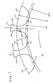
- teeth 15 are separated by tooth grooves 14. Facing tooth surfaces 12a and 12b are connected to each other by a tooth gap bottom portion 13.
- a front tooth surface 12a, on the front side of a tooth in the rotational direction of the sprocket 11, and a rear tooth surface 12b of the same tooth, are symmetrically formed on the right and left sides with respect to the center line x of a tooth 15, which connects the rotation center o ( FIG. 2 ) of the sprocket 11 and the center of the tooth 15 at the root thereof.
- the tooth surface 12a and the tooth surface 12b each have a substantially concave curvature in a section plane perpendicular to the sprocket's axis of rotation.
- the tooth gap bottom portion 13 is arc-shaped, with an arc radius ri 13 .
- the tooth surface 12a and tooth surface 12b having a substantially concave curvature, and are smoothly and continuously connected to each other by the tooth gap bottom portion 13.
- the tooth form in the sprocket shown in FIG.1 has portions, on the tooth head side of the pitch circle pc, where distances from the center line x to the front tooth surface 12a, and to a rear tooth surface 12b, are larger than the distance pt in the pitch circle pc.
- FIG. 1 the diameter df of a tooth gap bottom circle in the ISO tooth form is shown by broken lines for comparison purposes.
- a diameter df 13 of the tooth gap bottom circle is smaller than a diameter df of a tooth gap bottom circle in an ISO tooth form. That is, df 13 ⁇ df.
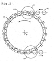
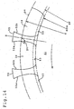
- FIGs. 2 , 3 and 4 show the sprocket as a driving sprocket, used to drive a roller chain 61.
- each roller 62 of the roller chain 61 engages with the sprocket 11 in a tooth groove to drive the roller chain 61.
- a preceding roller 62a is engaged with the sprocket 11 in a tooth groove 14
- the following roller 62b is engaged with a front tooth surface 12a of a next tooth.
- each roller 62 is moved in its tooth groove 14. As illustrated in FIG. 2 , the position of the roller 62 in the tooth groove shifts from the front tooth surface 12a to the rear tooth surface 12b of a preceding tooth. At the location B ( FIG. 2 ), the chain disengages from the sprocket. As shown in FIG. 4 , when a following roller 62c is engaged with a rear tooth surface 12b, the preceding roller 62d is smoothly disengaged from the rear tooth surface 12b of the preceding sprocket tooth of the sprocket.
- the tooth form of the sprocket 11, shown in FIGS. 1 and 2 has a portion where the distance from the tooth center line x to the front side in at least a part of the tooth head portion of tooth 15 is equal to or greater than the distance from the tooth center line to the front side of the tooth in the pitch circle pc.
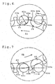
- a preceding roller 62a engages with the sprocket 11 in a tooth groove 14
- the following roller 62b engages with a front tooth surface 12a of a succeeding sprocket tooth.
- the magnitude of the pulse motion of the roller chain 61 due to polygonal motion is reduced. Vibration of the roller chain, and the speed change of the roller chain 61, are also reduced.
- the vibration of the roller chain 61 is reduced, noise reduction can be achieved, and change in tension is also reduced, so increased chain life can be realized.
- the tooth gap bottom circle diameter df 13 of the sprocket 11 is smaller than the tooth gap bottom circle diameter df for the ISO tooth form.
- each roller 62 moves while rolling in a tooth groove 14.
- the position of the roller 62 in the tooth groove 14 moves from a front tooth surface 12a to a rear tooth surface 12b.
- the preceding roller 62d is smoothly disengaged from a rear surface 12b of a preceding tooth.
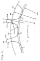
- teeth 25 are separated by tooth grooves 24, in which facing tooth surfaces 22a and 22b are continuously connected to each other by tooth gap bottom portion 23.
- a front tooth surface 22a and a rear tooth surface 22b are symmetrical on the right and left sides of the center line x of the tooth 25.
- Each of the tooth surfaces 22a and 22b has a substantially convex curve.
- the tooth gap bottom portion 23 is arc-shaped, with an arc radius ri 23 .
- the tooth surface 22a and tooth surface 22b, both of which have a substantially convex curve, are smoothly and continuously connected to each other by the tooth gap bottom portion 23.
- the tooth form in the sprocket has portions, on the tooth head side of the pitch circle pc, where distances from the center line x to the front tooth surface 22a, and to a rear tooth surface 22b, are larger than the distance pt in the pitch circle pc.
- the diameter df 23 of the tooth gap bottom circle is also smaller than the diameter df of a tooth gap bottom circle in an ISO tooth form. That is, df 23 ⁇ df, the diameter df being the diameter of the tooth gap bottom circle in the ISO tooth form, as shown by a broken line for comparison purposes.
- the tooth form in the sprocket has portions, on the tooth head side of the pitch circle pc, where distances from the center line x to the front tooth surface 22a are larger than the distance pt in the pitch circle pc.
- the following roller 62b engages with a front tooth surface 22a. Therefore, the magnitude of pulse motion of the roller chain 61 due to the polygonal motion is reduced. As a result, the vibration of the roller chain 61 is reduced and the speed change of the roller chain 61 is also reduced. Furthermore, since the vibration of the roller chain 61 is reduced, a noise reduction effect is realized, and changes in tension are also reduced so that life of the roller chain 61 is increased.
- the tooth gap bottom circle diameter df 23 is smaller than the tooth gap bottom circle diameter df for the ISO tooth form, while the rollers 62 move while rolling in tooth grooves 24 as the sprocket 21 rotates counterclockwise, the position of the roller 62 in the tooth groove 24 moves from a front tooth surface 22a to a rear tooth surface 22b. Then, upon disengagement, when a following roller 62c is engaged with a rear tooth surface 22b, the preceding roller 62d is smoothly disengaged from a rear tooth surface 22b of a preceding sprocket tooth.
- teeth 35 are separated by tooth grooves 34, in which facing tooth surfaces 32a and 32b are continuously connected to each other by tooth gap bottom portion 33.
- a front tooth surface 32a and a rear tooth surface 32b are symmetrical on the right and left sides of the center line x of the tooth 35.
- the faces of the teeth outside the pitch circle are linear in cross section, and the tooth surfaces 32a and 32b are in the form of substantially parallel planes.
- the tooth gap bottom portion 33 is arc-shaped, with an arc radius ri 33 .
- the tooth surface 32a and tooth surface 32b, both of which are substantially planar, are smoothly and continuously connected to each other by the tooth gap bottom portion 33.
- the tooth form in the sprocket has portions, on the tooth head side of the pitch circle pc, where distances from the center line x to the front tooth surface 32a, and to a rear tooth surface 32b, are equal to the distance pt in the pitch circle pc.
- the diameter df 33 of the tooth gap bottom circle is also smaller than the diameter df of a tooth gap bottom circle in an ISO tooth form. That is, df 33 ⁇ df, the diameter df being the diameter of the tooth gap bottom circle in the ISO tooth form, as shown by a broken line for comparison purposes.
- the tooth form in the sprocket has portions, on the tooth head side of the pitch circle pc, where the distances from the center line x to the front tooth surface 32a are substantially equal to the distance pt in the pitch circle pc.
- the tooth gap bottom circle diameter df 33 is smaller than the tooth gap bottom circle diameter df for the ISO tooth form, while the rollers 62 move while rolling in tooth grooves 34 as the sprocket 31 rotates counterclockwise, the position of the roller 62 in the tooth groove 34 moves from a front tooth surface 32a to a rear tooth surface 32b. Then, upon disengagement, when a following roller 62c is engaged with a rear tooth surface 32b, the preceding roller 62d is smoothly disengaged from a rear tooth surface 32b of a preceding sprocket tooth.
- teeth 45 are separated by tooth grooves 44, in which facing tooth surfaces 42a and 42b are continuously connected to each other by tooth gap bottom portion 43.
- the front tooth surface 42a and a rear tooth surface 42b are asymmetrical on the right and left sides of the center line x of the tooth 45, which intersects the center of the sprocket and the center of tooth at the root.
- the tooth surface 42a has a substantially concave curvature, while the tooth surface 42b has substantially the same curvature as the tooth surface of the ISO tooth form.
- the tooth gap bottom portion 43 arc-shaped, with an arc radius ri 43 .
- the concave tooth surface 42a, and the tooth surface 42b, are smoothly and continuously connected by the tooth gap bottom portion 43.
- the tooth form in the sprocket has portions, on the tooth head side of the pitch circle pc, where the distance from the center line x to the front tooth surface 42a is larger than the distance pt in the pitch circle pc.
- the diameter df 43 of the tooth gap bottom circle is also smaller than the diameter df of a tooth gap bottom circle in an ISO tooth form. That is, df 43 ⁇ df, the diameter df being the diameter of the tooth gap bottom circle in the ISO tooth form, as shown by a broken line for comparison purposes.
- the tooth form in the sprocket has portions, on the tooth head side of the pitch circle pc, where the distances from the center line x to the front tooth surface 42a are larger than the distance pt in the pitch circle pc.
- the tooth gap bottom circle diameter df 43 is smaller than the tooth gap bottom circle diameter df for the ISO tooth form, while the rollers 62 move while rolling in tooth grooves 44 as the sprocket 41 rotates counterclockwise, the position of the roller 62 in the tooth groove 44 moves from a front tooth surface 42a to a rear tooth surface 42b. Then, upon disengagement, when a following roller 62c is engaged with a rear tooth surface 42b, the preceding roller 62d is smoothly disengaged from a rear tooth surface 42b of a preceding sprocket tooth.
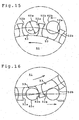
- teeth 55 are separated by tooth grooves 54, in which facing tooth surfaces 52a and 52b are continuously connected to each other by tooth gap bottom portion 53.
- a front tooth surface 52a and a rear tooth surface 52b are symmetrically formed on the right and left sides with respect to the center line x of the tooth 55.
- the tooth surface 52a and the tooth surface 52b each have a substantially concave curve in its section.
- the tooth gap bottom portion 53 is formed of a part of the circumference of a tooth gap bottom circle.
- the tooth surfaces 52a and 52b are both in the form of a substantially concave curve and are smoothly and continuously connected continued to the tooth gap bottom portion 53 by round portions.
- the tooth form in the sprocket has portions, on the tooth head side of the pitch circle pc, where the distances from the center line x to the front tooth surface 52a, and to a rear tooth surface 52b, are larger than the distance pt in the pitch circle pc.
- the diameter df 53 of the tooth gap bottom circle is smaller than a diameter df of the tooth gap bottom circle in an ISO tooth form. That is df 53 ⁇ df.
- the diameter df of a tooth gap bottom circle in the ISO tooth form is shown by broken lines for comparison.
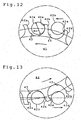
- the sprocket 51 is a driving sprocket, as shown in FIG. 15 , at the engagement of the sprocket 51 and the roller chain 61, while a preceding roller 62a is engaged with the sprocket 51 in a tooth groove 54, the following roller 62b is engaged with a front tooth surface 52a. At this time, the center of the preceding roller 62a and the center of the following roller 62b are positioned on the same horizontal line. Furthermore, although not shown, as the sprocket rotates, the position of the roller 62 in the tooth groove 54 of the sprocket 51 moves from a front tooth surface 52a to a rear tooth surface 52b. As shown in FIG.
- the tooth form in the sprocket has portions, on the tooth head side of the pitch circle pc, where the distance from the centerline x to the front tooth surface 52a is larger than the distance pt in the pitch circle pc.
- the tooth gap bottom circle diameter df 53 is smaller than the tooth gap bottom circle diameter df for the ISO tooth form, while the rollers 62 move while rolling in tooth grooves 54 as the sprocket 51 rotates counterclockwise, the position of the roller 62 in the tooth groove 54 moves from a front tooth surface 52a to a rear tooth surface 52b. Then, upon disengagement, when a following roller 62c is engaged with a rear tooth surface 52b, the preceding roller 62d is smoothly disengaged from a rear tooth surface 52b of a preceding sprocket tooth.
Landscapes
- Engineering & Computer Science (AREA)
- General Engineering & Computer Science (AREA)
- Mechanical Engineering (AREA)
- Gears, Cams (AREA)
- Devices For Conveying Motion By Means Of Endless Flexible Members (AREA)
Claims (4)
- Zahnrad für eine Kette, bei der eine Mehrzahl von Zähnen (15; 25; 55) durch Zahnnuten (14; 24; 54) getrennt ist, von denen jede durch einander gegenüberliegende Zahnflanken (12a und 12b; 22a und 22b; 52a und 52b) gebildet ist, die miteinander über einen Zahngrundbereich (13; 23; 53) verbunden sind, wobei die Gestalt jedes Zahns besagten Zahnrads (11; 21; 51) symmetrisch bezüglich der Zahnmittellinie (x) jeden Zahns (15; 25; 55) ist, die den Drehmittelpunkt (o) besagten Zahnrads (11; 21; 51) und ein vorderes Ende besagten Zahns (15; 25; 55) verbindet, die Gestalt jedes Zahns (15; 25; 55) besagten Zahnrads (11; 21; 51) einen Bereich hat, in dem ein Abstand auf der Zahnkopfseite des Teilkreises (pc) von der Zahnmittellinie (x) zu einer Zahnflanke (12a; 22a) auf der Vorderseite in Drehrichtung des Zahnrads (11; 21; 51) größer als der Abstand (pt) besagten Teilkreises (pc) zwischen der Zahnmittellinie (x) und der vorderen Flanke (12a; 22a; 52a) des Zahnes (15; 25; 55) ist, und die Gestalt jedes Zahns (15; 25; 55) besagten Zahnrads (11; 21; 51) eine größere Breite an der vorderen Endseite besagten Zahns (15; 25; 55) als die Breite besagten Zahns (15; 25; 55) in einem Teilkreis besagten Zahnrads (11; 21; 51) hat.
- Zahnrad nach Anspruch 1, dadurch gekennzeichnet, dass der Zahngrundkreisdurchmesser (df13; df23; df53) des Zahnrads (11; 21; 51) kleiner als der Zahngrundkreisdurchmesser (df) einer ISO-Zahnform für die gleiche Kette und den gleichen Teilkreisdurchmesser (d) ist.
- Kettengetriebe, aufweisend eine Rollen- oder Buchsenkette und ein Zahnrad (11; 21; 51) bei dem eine Mehrzahl von Zähnen (15; 25; 55) durch Zahnnuten (14; 24; 54) getrennt ist, von denen jede durch einander gegenüberliegende Zahnflanken (12a und 12b; 22a und 22b; 52a und 52b) gebildet ist, die miteinander über einen Zahngrund verbunden sind, wobei die Rollen (62) oder Buchsen der Kette in Eingriff mit den Nuten sind, und die Gestalt jedes Zahns (15; 25; 55) des Zahnrads (11; 21; 51) einen Bereich hat, in dem ein Abstand auf der Zahnkopfseite des Teilkreises (pc) von der Zahnmittellinie (x), die den Drehmittelpunkt (o) des Zahnrads (11; 21; 51) und die Mitte des Zahns (15; 25; 55) verbindet, zu einer Zahnflanke (12a; 22a; 52a) auf der Vorderseite in Drehrichtung des Zahnrads (11; 21; 51) gleich oder größer als der Abstand (pt) besagten Teilkreises (pc) zwischen der Zahnmittellinie (x) und der Vorderseite (12a; 22a; 52a) des Zahnes (15; 25; 55) ist.
- Kettengetriebe nach Anspruch 3, dadurch gekennzeichnet, dass der Zahngrundkreisdurchmesser (df13; df23; df53) des Zahnrads (11; 21; 51) kleiner als der Zahngrundkreisdurchmesser (df) einer ISO-Zahnform für die gleiche Kette und den gleichen Teilkreisdurchmesser (d) ist.
Applications Claiming Priority (2)
| Application Number | Priority Date | Filing Date | Title |
|---|---|---|---|
| JP2003271106 | 2003-07-04 | ||
| JP2003271106A JP3886130B2 (ja) | 2003-07-04 | 2003-07-04 | チェーン用スプロケット |
Publications (2)
| Publication Number | Publication Date |
|---|---|
| EP1493946A1 EP1493946A1 (de) | 2005-01-05 |
| EP1493946B1 true EP1493946B1 (de) | 2008-04-23 |
Family
ID=33432385
Family Applications (1)
| Application Number | Title | Priority Date | Filing Date |
|---|---|---|---|
| EP04015565A Expired - Lifetime EP1493946B1 (de) | 2003-07-04 | 2004-07-02 | Zahnrad für eine Kette |
Country Status (5)
| Country | Link |
|---|---|
| US (1) | US7128673B2 (de) |
| EP (1) | EP1493946B1 (de) |
| JP (1) | JP3886130B2 (de) |
| CN (1) | CN100347469C (de) |
| DE (1) | DE602004013223T2 (de) |
Families Citing this family (26)
| Publication number | Priority date | Publication date | Assignee | Title |
|---|---|---|---|---|
| JP4485311B2 (ja) * | 2004-09-30 | 2010-06-23 | 株式会社椿本チエイン | チェーン用スプロケットの歯切り方法 |
| JP4357402B2 (ja) | 2004-10-18 | 2009-11-04 | 株式会社椿本チエイン | 搬送装置 |
| JP3970281B2 (ja) * | 2004-11-19 | 2007-09-05 | 株式会社椿本チエイン | チェーン伝動装置 |
| JP4685429B2 (ja) * | 2004-12-17 | 2011-05-18 | 株式会社椿本チエイン | チェーン用のスプロケット |
| US7740555B2 (en) * | 2005-10-14 | 2010-06-22 | Borgwarner Inc. | Sprocket tooth profile for a roller or bush chain |
| JP4318264B2 (ja) * | 2006-12-27 | 2009-08-19 | 株式会社椿本チエイン | エンジン用タイミングチェーン伝動装置 |
| JP4823083B2 (ja) * | 2007-01-24 | 2011-11-24 | 株式会社椿本チエイン | チェーン伝動装置 |
| JP2009197869A (ja) * | 2008-02-20 | 2009-09-03 | Tsubakimoto Chain Co | チェーン用スプロケット |
| JP4468466B2 (ja) * | 2008-05-13 | 2010-05-26 | 株式会社椿本チエイン | チェーン用スプロケット |
| JP4633819B2 (ja) * | 2008-05-14 | 2011-02-16 | 株式会社椿本チエイン | チェーン用スプロケット |
| US20130345005A1 (en) * | 2012-06-21 | 2013-12-26 | Tai-Her Yang | Anti-Detachment Chainwheel having Forced Recessed Face at Chain Tooth Root Portion |
| US20130345006A1 (en) * | 2012-06-21 | 2013-12-26 | Tai-Her Yang | Chainwheel Enabling Positive Rotational Transmission and Reverse Rotational Sliding Features |
| DE102012106708A1 (de) | 2012-07-24 | 2014-10-30 | Nordischer Maschinenbau Rud. Baader Gmbh + Co. Kg | Kettenglied, Stützkette und Stützvorrichtung |
| USD731569S1 (en) * | 2012-07-24 | 2015-06-09 | Nordischer Maschinenbau Rud. Baader Gmbh + Co. Kg | Sprocket for chain link |
| USD734590S1 (en) | 2012-07-24 | 2015-07-14 | Nordischer Maschinenbau Rud. Baader Gmbh + Co. Kg | Chain link |
| US10000256B2 (en) * | 2014-01-23 | 2018-06-19 | Shimano Inc. | Bicycle sprocket |
| JP6226773B2 (ja) | 2014-02-24 | 2017-11-08 | 株式会社椿本チエイン | スプロケット |
| DE102015219522B4 (de) * | 2014-10-14 | 2025-07-24 | Sram Deutschland Gmbh | Mehrfach-Kettenradanordnung für eine Hinterradnabe |
| SG10201909092SA (en) | 2015-03-31 | 2019-11-28 | Fisher & Paykel Healthcare Ltd | A user interface and system for supplying gases to an airway |
| ES2924814T3 (es) * | 2015-08-25 | 2022-10-11 | Miranda & Irmao Lda | Sistema de transmisión y su uso |
| JP2018001773A (ja) * | 2016-06-27 | 2018-01-11 | 株式会社シマノ | 自転車用スプロケット、及び自転車用スプロケット組立体 |
| GB2607540B (en) | 2016-08-11 | 2023-03-29 | Fisher & Paykel Healthcare Ltd | A collapsible conduit, patient interface and headgear connector |
| JP7011166B2 (ja) * | 2018-03-30 | 2022-01-26 | 株式会社椿本チエイン | スプロケット及び伝動機構 |
| JP7017977B2 (ja) * | 2018-04-18 | 2022-02-09 | 大同工業株式会社 | プッシュチェーン |
| KR102389458B1 (ko) * | 2020-03-10 | 2022-04-25 | 동양피씨(주) | 구동부가 개선된 수직 순환식 주차장치 |
| ZA202307747B (en) * | 2022-09-12 | 2025-08-27 | Tsubakimoto Chain Co | Sprocket and chain drive system |
Family Cites Families (13)
| Publication number | Priority date | Publication date | Assignee | Title |
|---|---|---|---|---|
| US3899932A (en) * | 1973-12-19 | 1975-08-19 | Roger Owen Durham | Chain retention device for elliptical sprockets |
| JPS6011270B2 (ja) * | 1976-03-03 | 1985-03-25 | リコー時計株式会社 | 歯車列における逆伝達防止機構 |
| US4200000A (en) | 1978-10-04 | 1980-04-29 | Societe Suisse Pour L'industrie Horlogere Management Services S.A. | Gear train |
| AU8752782A (en) * | 1981-08-24 | 1983-03-03 | Cornelis Johannes Maria Beerens | Chain saw bar and sprocket |
| IT1237281B (it) * | 1989-11-21 | 1993-05-27 | Campagnolo Srl | Ruota dentata per bicicletta e ruota libera per biciclette includente una pluralita' di tali ruote dentate |
| FR2678890B3 (fr) * | 1991-07-09 | 1993-10-15 | Bg Innovations | Roue dentee pour transmission par chaine, en particulier pour cycle. |
| EP0561380B1 (de) * | 1992-03-18 | 1998-06-03 | Mannesmann Sachs Aktiengesellschaft | Kettenantrieb-Mechanismus für ein Fahrrad oder dergleichen |
| US5921878A (en) | 1996-07-03 | 1999-07-13 | Cloyes Gear And Products, Inc. | Roller chain drive system having improved noise characteristics |
| BR9710575A (pt) * | 1996-07-25 | 1999-09-14 | Cloyes Gear & Products Inc | Roda dentada de corrente de rolos, de engate aleatório, com caracterìsticas de ruìdo aperfeiçoadas. |
| CA2246131C (en) | 1997-10-03 | 2007-06-05 | Borg-Warner Automotive, Inc. | Randomized sprocket for roller chain |
| JP3212288B2 (ja) * | 1999-03-02 | 2001-09-25 | 三協オイルレス工業株式会社 | チェーン駆動機構装置 |
| US6736744B1 (en) * | 2000-11-01 | 2004-05-18 | Borgwarner, Inc. | Roller chain sprocket for preventing substantially radial impact with chain rollers |
| EP1235003A1 (de) * | 2001-02-23 | 2002-08-28 | Morse Tec Europe S.p.A. | Rollenkettenrad mit unterschiedlichen Zahnprofilen auf dem gleichem Kettenrad |
-
2003
- 2003-07-04 JP JP2003271106A patent/JP3886130B2/ja not_active Expired - Fee Related
-
2004
- 2004-07-02 DE DE602004013223T patent/DE602004013223T2/de not_active Expired - Lifetime
- 2004-07-02 US US10/884,874 patent/US7128673B2/en not_active Expired - Fee Related
- 2004-07-02 EP EP04015565A patent/EP1493946B1/de not_active Expired - Lifetime
- 2004-07-05 CN CNB2004100634639A patent/CN100347469C/zh not_active Expired - Fee Related
Also Published As
| Publication number | Publication date |
|---|---|
| US7128673B2 (en) | 2006-10-31 |
| CN1576652A (zh) | 2005-02-09 |
| JP2005030501A (ja) | 2005-02-03 |
| US20050009655A1 (en) | 2005-01-13 |
| EP1493946A1 (de) | 2005-01-05 |
| JP3886130B2 (ja) | 2007-02-28 |
| CN100347469C (zh) | 2007-11-07 |
| DE602004013223T2 (de) | 2009-05-14 |
| DE602004013223D1 (de) | 2008-06-05 |
Similar Documents
| Publication | Publication Date | Title |
|---|---|---|
| EP1493946B1 (de) | Zahnrad für eine Kette | |
| US9493211B2 (en) | Chainring | |
| EP1451489B1 (de) | Rollenkettenrad mit hinzugefügter sehnenteilungsverminderung | |
| US9062758B2 (en) | Chainring | |
| JP4357402B2 (ja) | 搬送装置 | |
| JP4685429B2 (ja) | チェーン用のスプロケット | |
| KR101838926B1 (ko) | 듀얼타입의 파동기어장치 | |
| JP2009275779A (ja) | チェーン用スプロケット | |
| JP2009197869A (ja) | チェーン用スプロケット | |
| EP0818644B1 (de) | Zahnprofil für ein Rollenkettenrad | |
| JP3970281B2 (ja) | チェーン伝動装置 | |
| US6413180B1 (en) | Power transmitting mechanism with silent chain and sprockets | |
| US6910397B2 (en) | Toothing assembly | |
| US11661998B2 (en) | Power transmission chain | |
| JP2024061066A (ja) | スプロケット |
Legal Events
| Date | Code | Title | Description |
|---|---|---|---|
| PUAI | Public reference made under article 153(3) epc to a published international application that has entered the european phase |
Free format text: ORIGINAL CODE: 0009012 |
|
| AK | Designated contracting states |
Kind code of ref document: A1 Designated state(s): AT BE BG CH CY CZ DE DK EE ES FI FR GB GR HU IE IT LI LU MC NL PL PT RO SE SI SK TR |
|
| AX | Request for extension of the european patent |
Extension state: AL HR LT LV MK |
|
| 17P | Request for examination filed |
Effective date: 20050521 |
|
| AKX | Designation fees paid |
Designated state(s): DE FR GB NL |
|
| GRAP | Despatch of communication of intention to grant a patent |
Free format text: ORIGINAL CODE: EPIDOSNIGR1 |
|
| GRAS | Grant fee paid |
Free format text: ORIGINAL CODE: EPIDOSNIGR3 |
|
| GRAA | (expected) grant |
Free format text: ORIGINAL CODE: 0009210 |
|
| RIN1 | Information on inventor provided before grant (corrected) |
Inventor name: SONODA, MASATOSHI,C/O TSUBAKIMOTO CHAIN CO. Inventor name: SAITOH, TOYONAGA, C/O TSUBAKIMOTO CHAIN CO. Inventor name: KUBO, AIZOH |
|
| AK | Designated contracting states |
Kind code of ref document: B1 Designated state(s): DE FR GB NL |
|
| REG | Reference to a national code |
Ref country code: GB Ref legal event code: FG4D |
|
| REF | Corresponds to: |
Ref document number: 602004013223 Country of ref document: DE Date of ref document: 20080605 Kind code of ref document: P |
|
| ET | Fr: translation filed | ||
| PLBE | No opposition filed within time limit |
Free format text: ORIGINAL CODE: 0009261 |
|
| STAA | Information on the status of an ep patent application or granted ep patent |
Free format text: STATUS: NO OPPOSITION FILED WITHIN TIME LIMIT |
|
| 26N | No opposition filed |
Effective date: 20090126 |
|
| PGFP | Annual fee paid to national office [announced via postgrant information from national office to epo] |
Ref country code: GB Payment date: 20130626 Year of fee payment: 10 |
|
| PGFP | Annual fee paid to national office [announced via postgrant information from national office to epo] |
Ref country code: NL Payment date: 20130716 Year of fee payment: 10 |
|
| REG | Reference to a national code |
Ref country code: NL Ref legal event code: V1 Effective date: 20150201 |
|
| GBPC | Gb: european patent ceased through non-payment of renewal fee |
Effective date: 20140702 |
|
| PG25 | Lapsed in a contracting state [announced via postgrant information from national office to epo] |
Ref country code: NL Free format text: LAPSE BECAUSE OF NON-PAYMENT OF DUE FEES Effective date: 20150201 |
|
| PG25 | Lapsed in a contracting state [announced via postgrant information from national office to epo] |
Ref country code: GB Free format text: LAPSE BECAUSE OF NON-PAYMENT OF DUE FEES Effective date: 20140702 |
|
| REG | Reference to a national code |
Ref country code: FR Ref legal event code: PLFP Year of fee payment: 13 |
|
| REG | Reference to a national code |
Ref country code: FR Ref legal event code: PLFP Year of fee payment: 14 |
|
| PGFP | Annual fee paid to national office [announced via postgrant information from national office to epo] |
Ref country code: FR Payment date: 20170613 Year of fee payment: 14 |
|
| PG25 | Lapsed in a contracting state [announced via postgrant information from national office to epo] |
Ref country code: FR Free format text: LAPSE BECAUSE OF NON-PAYMENT OF DUE FEES Effective date: 20180731 |
|
| PGFP | Annual fee paid to national office [announced via postgrant information from national office to epo] |
Ref country code: DE Payment date: 20190618 Year of fee payment: 16 |
|
| REG | Reference to a national code |
Ref country code: DE Ref legal event code: R119 Ref document number: 602004013223 Country of ref document: DE |
|
| PG25 | Lapsed in a contracting state [announced via postgrant information from national office to epo] |
Ref country code: DE Free format text: LAPSE BECAUSE OF NON-PAYMENT OF DUE FEES Effective date: 20210202 |