EP1493532A1 - Capteur de position d'outil a détection déportée - Google Patents
Capteur de position d'outil a détection déportée Download PDFInfo
- Publication number
- EP1493532A1 EP1493532A1 EP04356107A EP04356107A EP1493532A1 EP 1493532 A1 EP1493532 A1 EP 1493532A1 EP 04356107 A EP04356107 A EP 04356107A EP 04356107 A EP04356107 A EP 04356107A EP 1493532 A1 EP1493532 A1 EP 1493532A1
- Authority
- EP
- European Patent Office
- Prior art keywords
- tap
- tool
- tapping
- probe
- position sensor
- Prior art date
- Legal status (The legal status is an assumption and is not a legal conclusion. Google has not performed a legal analysis and makes no representation as to the accuracy of the status listed.)
- Granted
Links
- 238000001514 detection method Methods 0.000 title abstract description 26
- 238000010079 rubber tapping Methods 0.000 claims abstract description 62
- 238000006073 displacement reaction Methods 0.000 claims abstract description 16
- 239000000523 sample Substances 0.000 claims description 33
- 230000005540 biological transmission Effects 0.000 claims description 25
- 238000011144 upstream manufacturing Methods 0.000 claims description 24
- 230000002950 deficient Effects 0.000 description 4
- 238000003754 machining Methods 0.000 description 4
- 230000007547 defect Effects 0.000 description 3
- 230000010354 integration Effects 0.000 description 3
- 238000004519 manufacturing process Methods 0.000 description 2
- 239000000463 material Substances 0.000 description 2
- 230000007423 decrease Effects 0.000 description 1
- 238000012423 maintenance Methods 0.000 description 1
- 238000005259 measurement Methods 0.000 description 1
- 230000009347 mechanical transmission Effects 0.000 description 1
- 230000007935 neutral effect Effects 0.000 description 1
- 210000000056 organ Anatomy 0.000 description 1
- 230000035515 penetration Effects 0.000 description 1
Images


Classifications
-
- H—ELECTRICITY
- H01—ELECTRIC ELEMENTS
- H01H—ELECTRIC SWITCHES; RELAYS; SELECTORS; EMERGENCY PROTECTIVE DEVICES
- H01H3/00—Mechanisms for operating contacts
- H01H3/02—Operating parts, i.e. for operating driving mechanism by a mechanical force external to the switch
- H01H3/16—Operating parts, i.e. for operating driving mechanism by a mechanical force external to the switch adapted for actuation at a limit or other predetermined position in the path of a body, the relative movement of switch and body being primarily for a purpose other than the actuation of the switch, e.g. for a door switch, a limit switch, a floor-levelling switch of a lift
-
- B—PERFORMING OPERATIONS; TRANSPORTING
- B23—MACHINE TOOLS; METAL-WORKING NOT OTHERWISE PROVIDED FOR
- B23G—THREAD CUTTING; WORKING OF SCREWS, BOLT HEADS, OR NUTS, IN CONJUNCTION THEREWITH
- B23G1/00—Thread cutting; Automatic machines specially designed therefor
- B23G1/16—Thread cutting; Automatic machines specially designed therefor in holes of workpieces by taps
- B23G1/18—Machines with one working spindle
-
- B—PERFORMING OPERATIONS; TRANSPORTING
- B23—MACHINE TOOLS; METAL-WORKING NOT OTHERWISE PROVIDED FOR
- B23Q—DETAILS, COMPONENTS, OR ACCESSORIES FOR MACHINE TOOLS, e.g. ARRANGEMENTS FOR COPYING OR CONTROLLING; MACHINE TOOLS IN GENERAL CHARACTERISED BY THE CONSTRUCTION OF PARTICULAR DETAILS OR COMPONENTS; COMBINATIONS OR ASSOCIATIONS OF METAL-WORKING MACHINES, NOT DIRECTED TO A PARTICULAR RESULT
- B23Q17/00—Arrangements for observing, indicating or measuring on machine tools
- B23Q17/22—Arrangements for observing, indicating or measuring on machine tools for indicating or measuring existing or desired position of tool or work
-
- H—ELECTRICITY
- H01—ELECTRIC ELEMENTS
- H01H—ELECTRIC SWITCHES; RELAYS; SELECTORS; EMERGENCY PROTECTIVE DEVICES
- H01H3/00—Mechanisms for operating contacts
- H01H3/32—Driving mechanisms, i.e. for transmitting driving force to the contacts
- H01H3/36—Driving mechanisms, i.e. for transmitting driving force to the contacts using belt, chain, or cord
-
- H—ELECTRICITY
- H01—ELECTRIC ELEMENTS
- H01H—ELECTRIC SWITCHES; RELAYS; SELECTORS; EMERGENCY PROTECTIVE DEVICES
- H01H3/00—Mechanisms for operating contacts
- H01H3/32—Driving mechanisms, i.e. for transmitting driving force to the contacts
- H01H3/46—Driving mechanisms, i.e. for transmitting driving force to the contacts using rod or lever linkage, e.g. toggle
-
- Y—GENERAL TAGGING OF NEW TECHNOLOGICAL DEVELOPMENTS; GENERAL TAGGING OF CROSS-SECTIONAL TECHNOLOGIES SPANNING OVER SEVERAL SECTIONS OF THE IPC; TECHNICAL SUBJECTS COVERED BY FORMER USPC CROSS-REFERENCE ART COLLECTIONS [XRACs] AND DIGESTS
- Y10—TECHNICAL SUBJECTS COVERED BY FORMER USPC
- Y10T—TECHNICAL SUBJECTS COVERED BY FORMER US CLASSIFICATION
- Y10T408/00—Cutting by use of rotating axially moving tool
- Y10T408/16—Cutting by use of rotating axially moving tool with control means energized in response to activator stimulated by condition sensor
Definitions
- the present invention relates to press tapping devices, in which a piece such as a cutting and tapping strip is held in a tool for forming and cutting the strip, the tool also being provided with less a tapping tool.
- These cutting and tapping tools are generally suitable for produce parts at a high rate from a continuous band.
- a unit of tapping in press comprising three sensors: a first sensor for detect the possible decline of the tap and its support; a second sensor for detect the displacement of the tapping pin; a third sensor for detect if the hole is free after tapping or if it remains blocked by a tap broken.
- tapping is not carried out so complete: the tap does not completely traverse the material, so the tapping is incomplete.
- a serious defect of these known detection devices is that it is necessary to adapt each time an appropriate device below the tapping tool, and this device must conform to the normal stroke of the tap.
- the settings of race are difficult or impossible because the detector is not accessible.
- Another disadvantage is that the detection devices are bulky, that is to say they occupy a significant place below the tapping tool, so that the detectors can not be placed very close to each other when it comes to making several parallel threads on the same product. It is thus impossible to realize close tapping, because of the necessary space requirement of the detection placed in the press support.
- the known devices are sensitive to the presence of chips tapping, which affects the reliability of the detections.
- the problem proposed by the present invention is to design a new tap position sensor structure for press tapping, which allows a use in a wide range of threads, and which allows setting the detection according to the desired end position of the tap.
- Another object of the invention is to design such a structure of Tap position sensor that is particularly reliable, and accurate, in order to detect with certainty the defective parts and extract them from the batch as soon as they manufacturing.
- Another object of the invention is to design such a position sensor taps that are particularly compact and easy to integrate into a tool sole below the tapping tool, so as to allow the close tapping.
- This combination of features allows, thanks to the cable of transmission, to deport the position detection means away from the area occupied by the tap, while avoiding measurement or detection errors introduced by the necessary mechanical transmission the tap to the position detecting means, and considerably facilitating the possibility of integration of the device into the tool sole area below of the tapping tool.
- the invention thus proposes an inexpensive solution, with a detector a portion of which is placed in the lower cavity provided under the tap in the sole of the tool, to feel the tap in order to pinpoint its position accurately low dead point, and to remotely transmit the tracking information up to the outside of the tool support in a way that best frees the space under the tap, which allows the close integration of several taps, and which allows the detection settings.
- the transmission cable may be bare, provided that it works pull and stay stretched and slide between two end brackets integral with the frame of the device.
- the transmission cable slides in a sheath itself integral with the frame of the device.
- the device displacement multiplier includes a multiplier lever having an arm upstream shorter than the downstream arm.
- the multiplier lever is bent, adapted to arrange, in the standby position, its upstream arm in horizontal orientation suitable for detect the vertical movement of a tap, and adapted to dispose, in said waiting position, at least part of its downstream arm in vertical orientation appropriate to ensure a horizontal departure of the transmission cable.
- the probe comprises a translational pusher vertical functionally related to the upstream arm of the multiplier lever by a transverse pin engaged in longitudinal translation along the upstream arm of the multiplier lever.
- the probe comprises an inverter lever oriented in a horizontal general direction and pivoting about a median axis horizontal, with its upstream end urged by the tap at the end of tapping, and with its downstream end coupled to the multiplier lever.
- the probe comprises a vertical pusher secured to the upstream arm itself arranged in a substantially horizontal orientation, and placed in line with the path of the tap to be detected.
- the multiplier lever is biased by a spring of call back to the waiting position.
- the spring is the means of return in position waiting for both the probe, the transmission cable, and the detection means position.
- Such a position sensor defined above can be integrated into a tool cutting with integrated tapping.
- the cutting tool integrated tapping includes two flanges, a tape support supporting the cutting strip, tools for cutting the strip, and at least one tool for tapping bearing a tap.
- the tool comprises at least one position sensor to remote sensor as defined above, with probe and device displacement multiplier that are integrated into the bottom flange of the tool in the area below the tapping tool.
- the transmission cable can be adapted to cross the bottom flange of the tool from the area below the tapping tool to the outside of the lower flange of the tool, the means for detecting position is then placed outside the lower flange of the tool, and being thus directly accessible by the user.
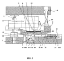
- the sensor of tap position according to the invention is shown in its position of use to inside an integrated tapping tool.
- This integrated tapping cutting tool includes a sole lower 1 and an upper sole 8, supporting all of the others elements.
- the integrated tapping tool has several positions bearing unrepresented cutting and forming tools, and a station comprising the tapping tool 11, shown in Figures 1, 3, 4, 5, 6 and 7.
- the material used by this tool is in the form of a strip 6, scrolling horizontally in the tool, on a tape support 4, which has guides 5 for its maintenance.
- the strip 6 has at least one hole 7 crossing that must be tapped.
- the hole may have been made for example by forming in a previous post of the tool.
- the tool thus formed is mounted on a press.
- the lower sole 1 rests on the table of the press, and the upper sole 8 is fixed to the slider of the press, the latter giving him a vertical movement.
- this vertical movement is taken up by a screw / nut device 9 which generates a rotational movement.
- the movement of rotation thus obtained is taken up by the tapping tool 11, which transmits to a tapping pin 12 a helical movement.
- Tapping pin 12 is shaped to carry a tap 14, located in front of the hole 7 to be tapped.
- tape support 4 can also be animated reciprocating vertical translation to accompany operations cutting and forming done on the other positions of the tool.
- the position of tapping is then adapted to this movement of the tape support 4.
- the tape support 4 in waiting position in Figure 1, we see that the tape support 4 is raised to the distance from the bottom flange 1, while at the bottom dead point illustrated in FIG. the tape support 4 is lowered closer to the lower sole 1. This vertical movement of the tape holder 4 does not affect the detection of the dead point bottom of the tap 14 by the means of the invention.
- the tap position sensor essentially comprises a feeler 15, a multiplier device of displacement 16, a transmission cable 17, and a position detecting means 18.
- the multiplier device 16 includes a multiplier lever 19 having an upstream arm 20 shorter than the downstream arm 21, and pivoted around of an intermediate horizontal transverse axis 22 at the junction between the upstream arm 20 and the downstream arm 21. It will be admitted, however, that multipliers that are articulated at one end could also be used.
- the multiplier lever 19 is bent, adapted to have, in the waiting position illustrated in Figure 1, its upstream arm 20 in horizontal orientation, and its downstream arm 21 in orientation vertical.
- a spring 19a urges the multiplier lever 19 towards its position waiting shown in Figure 1, with the downstream arm 21 in the vertical position and the arm upstream 20 in horizontal position.
- the probe 15 comprises a vertical pusher 23 secured to the upstream arm 20 and placed in line with the trajectory of the tap 14 to detect.
- the probe 15, integrated in the lower sole 1 of the tool and in the band support 4, is adapted to be biased by the distal end of the tap 14 at the end of the tapping.
- the displacement multiplier device 16 is biased by the probe or vertical pusher 23 for pivoting about its horizontal transverse axis intermediate 22 and to amplify the movement of the probe or vertical push 23 thanks to the difference in length of the upstream arm 20 and the downstream arm 21.
- the transmission cable 17 is coupled by its first end 17a to the multiplier device 16.
- the first end 17a transmission cable 17 is attached to the distal end of the downstream arm 21.
- Sa second end 17b, remote from the probe 15, is detected by the means position detection 18.
- the multiplier lever 19 with its spring 19a are mounted in a probe body 24 fixed in the lower sole 1 of the tool.
- the position detection means 18 is offset to the outside, away from the area of the tap 14 through the transmission cable 17, and is secured a detector body 25 itself attached to the lower flange 1 of the tool.
- the transmission cable 17 is advantageously slidably mounted in a sheath 26 which is itself fixed relative to the lower sole 1 of the tool.
- the position detection means 18 may for example be a sensor proximity, sensitive to the position of an end piece 27 mounted sliding in the detector body 25 and constituting the second end 17b of the cable of transmission 17.
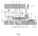
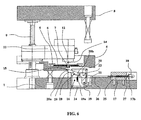
- the tap 14 passes through the hole 7 and its end pushes the vertical pushbutton 23 which then tilts the lever multiplier 19 to the inclined position illustrated in Figure 3, which lever multiplier 19 pulls the transmission cable 17 whose second end 17b is then detected by the position detection means 18 which confirms the presence tap 14 in neutral, confirming the good quality of tapping performed.
- a probe body 24 supporting a vertical pushbutton 23 constituting the probe itself and associated with a lever multiplier 19 pivotally mounted about a horizontal transverse axis intermediate 22, the multiplier lever 19 having two perpendicular arms, namely a generally horizontal upstream arm 20 and a downstream arm 21 generally vertical.
- the vertical pusher 23 is mounted vertically in alignment with the vertical stroke of the tap 14, and is functionally connected to the upstream arm 20 by a transverse pin 23a of the vertical pusher 23, the transverse pin 23a being engaged in an oblong horizontal slot 20a of the upstream arm 20.
- the vertical translation movement of the vertical pusher 23 is transformed into a rotational movement of the lever multiplier 19 which solicits then in translation the transmission cable 17 whose movements are detected by the position detection means 18.
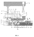
- Figures 4 and 5 illustrate respectively the standby position and the bottom dead center position of the tap 14.
- the spring 19a of the detector in standby position is mounted on the vertical pushbutton 23.
- the probe 15 comprises an inverter lever 28 oriented in a horizontal general direction and pivotable about a central axis 29 horizontal.
- the upstream end 28a is urged by the tap 14 at the end of the race. tapping, while its downstream end 28b is coupled to the multiplier lever 19 in the upstream end zone of its upstream arm 20.
- the multiplier lever 19 has an inverted position with respect to the position in Figures 1 to 4.
- the probe body 24, which contains the probe 15 and the displacement multiplier device 16 occupies a width L reduced under the area of the tap 14.
- This width L is reduced by the fact that the multiplier lever pivots around a horizontal axis 22 and constitutes itself a structure with a small width. It is the same with the inverter lever 28. In this way, it It is possible to place probe bodies 24 close to each other way to detect the position of taps that are themselves close to each other other.
Landscapes
- Engineering & Computer Science (AREA)
- Mechanical Engineering (AREA)
- Machine Tool Sensing Apparatuses (AREA)
- A Measuring Device Byusing Mechanical Method (AREA)
- Geophysics And Detection Of Objects (AREA)
- Cutting Tools, Boring Holders, And Turrets (AREA)
- Investigating Or Analyzing Materials By The Use Of Ultrasonic Waves (AREA)
- Percussion Or Vibration Massage (AREA)
- Ultra Sonic Daignosis Equipment (AREA)
- Dental Tools And Instruments Or Auxiliary Dental Instruments (AREA)
Abstract
Description
- un palpeur adapté pour être intégré dans une semelle d'outil de découpage et pour être sollicité par l'extrémité du taraud en fin de taraudage,
- un dispositif multiplicateur de déplacement, sollicité par le palpeur et adapté pour amplifier le déplacement du palpeur,
- un câble de transmission, couplé par une première extrémité au dispositif multiplicateur de déplacement, et dont une seconde extrémité est déportée à l'écart du palpeur,
- un moyen de détection de position, adapté pour détecter la position de la seconde extrémité du câble de transmission.
- la figure 1 est une vue de côté schématique en coupe d'un outil de découpage à taraudage intégré muni d'un capteur de position de taraud selon un premier mode de réalisation de l'invention, en position d'attente ;
- la figure 2 est une vue schématique de dessus de l'ensemble capteur de position de taraud de la figure 1, montrant la ligne de coupe A-A des vues de côté ;
- la figure 3 est une vue de côté en coupe de l'outil de découpage à taraudage intégré de la figure 1, en position de détection de point mort bas du taraud ;
- la figure 4 est une vue de côté en coupe d'un outil de découpage à taraudage intégré muni d'un capteur de position de taraud selon un second mode de réalisation de la présente invention, en position d'attente ;
- la figure 5 illustre en coupe l'outil de la figure 4, en position de détection de point mort bas du taraud ;
- la figure 6 est une vue de côté en coupe d'un outil de découpage à taraudage intégré muni d'un capteur de position de taraud selon un troisième mode de réalisation de la présente invention, en position d'attente ; et
- la figure 7 est une vue de côté en coupe illustrant l'outil de la figure 6 en position de détection de point mort bas du taraud.
Claims (10)
- Capteur de position de taraud pour taraudage sous presse, caractérisé en ce qu'il comprend :un palpeur (15) adapté pour être intégré dans une semelle d'outil de découpage (1) et pour être sollicité par l'extrémité du taraud (14) en fin de taraudage,un dispositif multiplicateur de déplacement (16), sollicité par le palpeur (15) et adapté pour amplifier le déplacement du palpeur (15),un câble de transmission (17), couplé par une première extrémité (17a) au dispositif multiplicateur de déplacement (16), et dont une seconde extrémité (17b) est déportée à l'écart du palpeur (15),un moyen de détection de position (18), adapté pour détecter la position de la seconde extrémité (17b) du câble de transmission (17).
- Capteur de position de taraud selon la revendication 1, caractérisé en ce que le câble de transmission (17) coulisse dans une gaine (26).
- Capteur de position de taraud selon l'une des revendications 1 ou 2, caractérisé en ce que le dispositif multiplicateur de déplacement (16) comprend un levier multiplicateur (19) ayant un bras amont (20) plus court que le bras aval (21).
- Capteur de position de taraud selon la revendication 3, caractérisé en ce que le levier multiplicateur (19) est coudé, adapté pour disposer, en position d'attente, son bras amont (20) en orientation horizontale appropriée pour détecter le mouvement vertical d'un taraud (14), et adapté pour disposer, dans ladite position d'attente, au moins une partie de son bras aval (21) en orientation verticale appropriée pour assurer un départ horizontal du câble de transmission (17).
- Capteur de position de taraud selon l'une des revendications 3 ou 4, caractérisé en ce que le palpeur (15) comprend un poussoir (23) à translation verticale fonctionnellement lié au bras amont (20) du levier multiplicateur (19) par une goupille transversale (23a) engagée en translation longitudinale le long du bras amont (20) du levier multiplicateur (19).
- Capteur de position de taraud selon l'une des revendications 3 ou 4, caractérisé en ce que le palpeur (15) comprend un levier inverseur (28) orienté en direction générale horizontale et pivotant autour d'un axe médian (29) horizontal, avec son extrémité amont (28a) sollicitée par le taraud (14) en fin de course de taraudage, et avec son extrémité aval (28b) couplée au levier multiplicateur (19).
- Capteur de position de taraud selon l'une des revendications 3 ou 4, caractérisé en ce que le palpeur (15) comprend un poussoir vertical (23) solidaire du bras amont (20) lui-même disposé en orientation sensiblement horizontale, et placé en ligne avec la trajectoire du taraud (14) à détecter.
- Capteur de position de taraud selon l'une quelconque des revendications 3 à 7, caractérisé en ce que le levier multiplicateur (19) est sollicité par un ressort (19a) de rappel en position d'attente.
- Outil de découpage à taraudage intégré, ayant une semelle inférieure (1), une semelle supérieure (8), un support de bande (4) soutenant une bande (6) à découper, des outils pour découper la bande (6), et au moins un outil de taraudage (11) portant un taraud (14), caractérisé en ce qu'il comprend au moins un capteur de position à détecteur déporté selon l'une quelconque des revendications 1 à 8, avec le palpeur (15) et le dispositif multiplicateur de déplacement (16) qui sont intégrés dans la semelle inférieure (1) de l'outil dans la zone au-dessous de l'outil de taraudage (11).
- Outil de découpage à taraudage intégré selon la revendication 9, caractérisé en ce que le câble de transmission (17) est adapté pour traverser la semelle inférieure (1) de l'outil depuis la zone au-dessous de l'outil de taraudage (11) jusqu'à l'extérieur de la semelle inférieure (1) de l'outil et le moyen de détection de position (18) est placé à l'extérieur de la semelle inférieure (1) de l'outil.
Applications Claiming Priority (2)
| Application Number | Priority Date | Filing Date | Title |
|---|---|---|---|
| FR0308241A FR2856946B1 (fr) | 2003-07-01 | 2003-07-01 | Capteur de position de taraud a detection deportee |
| FR0308241 | 2003-07-01 |
Publications (2)
| Publication Number | Publication Date |
|---|---|
| EP1493532A1 true EP1493532A1 (fr) | 2005-01-05 |
| EP1493532B1 EP1493532B1 (fr) | 2006-06-07 |
Family
ID=33427704
Family Applications (1)
| Application Number | Title | Priority Date | Filing Date |
|---|---|---|---|
| EP04356107A Expired - Lifetime EP1493532B1 (fr) | 2003-07-01 | 2004-06-21 | Capteur de position d'outil a détection déportée |
Country Status (8)
| Country | Link |
|---|---|
| US (1) | US7070509B2 (fr) |
| EP (1) | EP1493532B1 (fr) |
| JP (1) | JP3998149B2 (fr) |
| AT (1) | ATE328704T1 (fr) |
| CA (1) | CA2472884C (fr) |
| DE (1) | DE602004001095T2 (fr) |
| ES (1) | ES2267023T3 (fr) |
| FR (1) | FR2856946B1 (fr) |
Cited By (1)
| Publication number | Priority date | Publication date | Assignee | Title |
|---|---|---|---|---|
| CN107088686A (zh) * | 2017-05-31 | 2017-08-25 | 太仓市微贯机电有限公司 | 一种用于加工汽车发动机支架的耐用型攻牙机 |
Families Citing this family (6)
| Publication number | Priority date | Publication date | Assignee | Title |
|---|---|---|---|---|
| US8511945B2 (en) * | 2008-03-28 | 2013-08-20 | Quanser Consulting Inc. | Drill assembly and method to reduce drill bit plunge |
| CN102565874B (zh) * | 2012-01-13 | 2014-06-04 | 昆山乙盛机械工业有限公司 | 漏攻牙检测机 |
| US10291740B2 (en) * | 2014-09-03 | 2019-05-14 | Lenovo (Beijing) Co., Ltd. | Method and apparatus for determining application to be recommended |
| CN112247294B (zh) * | 2020-10-27 | 2022-11-18 | 厦门腾云塑胶有限公司 | 一种pvc水管攻螺纹装置 |
| CN115582587B (zh) * | 2022-12-14 | 2023-05-05 | 河北纵横集团丰南钢铁有限公司 | 一种套丝结构 |
| CN117359325B (zh) * | 2023-11-15 | 2024-04-02 | 西藏开投牧光生态发展有限公司 | 一种光伏支架成套设备新型生产工艺 |
Citations (3)
| Publication number | Priority date | Publication date | Assignee | Title |
|---|---|---|---|---|
| US5615471A (en) * | 1993-12-24 | 1997-04-01 | Rainer S.R.L. | Machine for machining sheet metal |
| DE19729263A1 (de) * | 1997-07-09 | 1999-01-14 | Iska Wolfgang Katz Verwaltungs | Vorrichtung zum Gewindeformen und -schneiden |
| US5967008A (en) * | 1998-12-29 | 1999-10-19 | The Shane Group, Inc. | Screw machine stock stop |
Family Cites Families (9)
| Publication number | Priority date | Publication date | Assignee | Title |
|---|---|---|---|---|
| US2689363A (en) * | 1946-12-16 | 1954-09-21 | Charles F Frye | Automatic stop and timer for machine tool control |
| US3200426A (en) * | 1962-03-28 | 1965-08-17 | Laughter Corp | Fluid driven and controlled tapping unit |
| FR2224046A5 (fr) * | 1973-03-29 | 1974-10-25 | Peugeot & Renault | |
| US3994612A (en) * | 1973-12-04 | 1976-11-30 | Regie Nationale Des Usines Renault | Arrangement for detecting the state of a tool |
| US4310269A (en) * | 1980-02-19 | 1982-01-12 | Northrop Corporation | Drill break-through sensor |
| JPH0314282Y2 (fr) * | 1985-06-24 | 1991-03-29 | ||
| US4718175A (en) * | 1985-07-01 | 1988-01-12 | Maho Aktiengesellschaft | Device for mechanical checking for toolbreakage in machine tools |
| US5086590A (en) * | 1989-06-16 | 1992-02-11 | George Athanasiou | Tool checking device for use with numerically controlled machines |
| US6665948B1 (en) * | 2002-09-05 | 2003-12-23 | Scott Hal Kozin | Drill bit penetration measurement system and method |
-
2003
- 2003-07-01 FR FR0308241A patent/FR2856946B1/fr not_active Expired - Fee Related
-
2004
- 2004-06-21 ES ES04356107T patent/ES2267023T3/es not_active Expired - Lifetime
- 2004-06-21 AT AT04356107T patent/ATE328704T1/de not_active IP Right Cessation
- 2004-06-21 DE DE602004001095T patent/DE602004001095T2/de not_active Expired - Lifetime
- 2004-06-21 US US10/872,668 patent/US7070509B2/en active Active
- 2004-06-21 EP EP04356107A patent/EP1493532B1/fr not_active Expired - Lifetime
- 2004-06-28 JP JP2004189680A patent/JP3998149B2/ja not_active Expired - Lifetime
- 2004-06-30 CA CA002472884A patent/CA2472884C/fr not_active Expired - Lifetime
Patent Citations (3)
| Publication number | Priority date | Publication date | Assignee | Title |
|---|---|---|---|---|
| US5615471A (en) * | 1993-12-24 | 1997-04-01 | Rainer S.R.L. | Machine for machining sheet metal |
| DE19729263A1 (de) * | 1997-07-09 | 1999-01-14 | Iska Wolfgang Katz Verwaltungs | Vorrichtung zum Gewindeformen und -schneiden |
| US5967008A (en) * | 1998-12-29 | 1999-10-19 | The Shane Group, Inc. | Screw machine stock stop |
Cited By (1)
| Publication number | Priority date | Publication date | Assignee | Title |
|---|---|---|---|---|
| CN107088686A (zh) * | 2017-05-31 | 2017-08-25 | 太仓市微贯机电有限公司 | 一种用于加工汽车发动机支架的耐用型攻牙机 |
Also Published As
| Publication number | Publication date |
|---|---|
| US20050003898A1 (en) | 2005-01-06 |
| DE602004001095D1 (de) | 2006-07-20 |
| JP3998149B2 (ja) | 2007-10-24 |
| US7070509B2 (en) | 2006-07-04 |
| EP1493532B1 (fr) | 2006-06-07 |
| ATE328704T1 (de) | 2006-06-15 |
| FR2856946A1 (fr) | 2005-01-07 |
| ES2267023T3 (es) | 2007-03-01 |
| CA2472884A1 (fr) | 2005-01-01 |
| FR2856946B1 (fr) | 2005-09-16 |
| CA2472884C (fr) | 2008-01-29 |
| DE602004001095T2 (de) | 2007-01-04 |
| JP2007007734A (ja) | 2007-01-18 |
Similar Documents
| Publication | Publication Date | Title |
|---|---|---|
| EP0145527B1 (fr) | Machine de découpe de matière en bande par jet fluide haute pression | |
| CA2472884C (fr) | Capteur de position de taraud a detection deportee | |
| EP0014120A1 (fr) | Pipette à déplacement positif | |
| BE1026614B1 (fr) | Trancheuse et procédé pour découper des pains successifs | |
| FR2738510A1 (fr) | Dispositif de blocage d'article pour la broche d'une machine-outil | |
| EP0267112B1 (fr) | Installation de filage de métal | |
| CH689613A5 (fr) | Dispositif de mesure de l'angle de pliage d'une tôle dans une presse. | |
| CH643356A5 (fr) | Tete de verification differentielle pour detecter des profils de pieces usinees. | |
| FR2540246A1 (fr) | Dispositif pour detecter des criques sur les brames d'acier sortant d'une coulee continue | |
| FR2659046A1 (fr) | Perfectionnements apportes aux machines a travailler le bois. | |
| FR2571874A1 (fr) | Procede de comptage et dispositif pour la mise en oeuvre du procede | |
| EP1269163A1 (fr) | Appareil pour l'inspection d'une surface | |
| FR2551319A1 (fr) | Appareil pour le triage des hamecons deformes ou casses sur les lignes dites palangres | |
| FR2569835A1 (fr) | Tete pour la mesure de diametres de pieces cylindriques | |
| EP0662437A1 (fr) | Dispositif de raccordement de bandes en un matériau souple | |
| EP0082159B1 (fr) | Dispositif pour positionner et inserer des rayons dans les trous d'un moyeu de roue a rayons | |
| EP2465702B1 (fr) | Dispositif de découpe d'enveloppes | |
| FR2512712A1 (fr) | Procede et dispositif pour regler la fin de course de relevage d'une lame de coupe dans une machine a couper telle qu'une scie a ruban horizontale | |
| FR2937280A1 (fr) | Machine de traitement de documents a entrainement ameliore. | |
| EP2324955A1 (fr) | Machine de toilage | |
| FR2698569A1 (fr) | Procédé et dispositif pour positionner les barres dans un tour. | |
| EP0612574B1 (fr) | Embarreur à entraînement multiple | |
| WO2004094104A1 (fr) | Dispositif de mesure automatique des dimensions d’un outil pour machine d’usinage | |
| FR2730377A3 (fr) | Dispositif de controle de nouage pour des appareils de liage dans des presses a balles | |
| FR2647202A1 (fr) | Tampon de controle d'un orifice taraude et dispositif pour le mettre en oeuvre |
Legal Events
| Date | Code | Title | Description |
|---|---|---|---|
| PUAI | Public reference made under article 153(3) epc to a published international application that has entered the european phase |
Free format text: ORIGINAL CODE: 0009012 |
|
| AK | Designated contracting states |
Kind code of ref document: A1 Designated state(s): AT BE BG CH CY CZ DE DK EE ES FI FR GB GR HU IE IT LI LU MC NL PL PT RO SE SI SK TR |
|
| AX | Request for extension of the european patent |
Extension state: AL HR LT LV MK |
|
| 17P | Request for examination filed |
Effective date: 20050701 |
|
| AKX | Designation fees paid |
Designated state(s): AT BE BG CH CY CZ DE DK EE ES FI FR GB GR HU IE IT LI LU MC NL PL PT RO SE SI SK TR |
|
| GRAP | Despatch of communication of intention to grant a patent |
Free format text: ORIGINAL CODE: EPIDOSNIGR1 |
|
| GRAS | Grant fee paid |
Free format text: ORIGINAL CODE: EPIDOSNIGR3 |
|
| GRAA | (expected) grant |
Free format text: ORIGINAL CODE: 0009210 |
|
| RAP1 | Party data changed (applicant data changed or rights of an application transferred) |
Owner name: PRONIC |
|
| AK | Designated contracting states |
Kind code of ref document: B1 Designated state(s): AT BE BG CH CY CZ DE DK EE ES FI FR GB GR HU IE IT LI LU MC NL PL PT RO SE SI SK TR |
|
| PG25 | Lapsed in a contracting state [announced via postgrant information from national office to epo] |
Ref country code: PL Free format text: LAPSE BECAUSE OF FAILURE TO SUBMIT A TRANSLATION OF THE DESCRIPTION OR TO PAY THE FEE WITHIN THE PRESCRIBED TIME-LIMIT Effective date: 20060607 Ref country code: NL Free format text: LAPSE BECAUSE OF FAILURE TO SUBMIT A TRANSLATION OF THE DESCRIPTION OR TO PAY THE FEE WITHIN THE PRESCRIBED TIME-LIMIT Effective date: 20060607 Ref country code: IE Free format text: LAPSE BECAUSE OF FAILURE TO SUBMIT A TRANSLATION OF THE DESCRIPTION OR TO PAY THE FEE WITHIN THE PRESCRIBED TIME-LIMIT Effective date: 20060607 Ref country code: AT Free format text: LAPSE BECAUSE OF FAILURE TO SUBMIT A TRANSLATION OF THE DESCRIPTION OR TO PAY THE FEE WITHIN THE PRESCRIBED TIME-LIMIT Effective date: 20060607 Ref country code: FI Free format text: LAPSE BECAUSE OF FAILURE TO SUBMIT A TRANSLATION OF THE DESCRIPTION OR TO PAY THE FEE WITHIN THE PRESCRIBED TIME-LIMIT Effective date: 20060607 Ref country code: SI Free format text: LAPSE BECAUSE OF FAILURE TO SUBMIT A TRANSLATION OF THE DESCRIPTION OR TO PAY THE FEE WITHIN THE PRESCRIBED TIME-LIMIT Effective date: 20060607 Ref country code: RO Free format text: LAPSE BECAUSE OF FAILURE TO SUBMIT A TRANSLATION OF THE DESCRIPTION OR TO PAY THE FEE WITHIN THE PRESCRIBED TIME-LIMIT Effective date: 20060607 |
|
| REG | Reference to a national code |
Ref country code: GB Ref legal event code: FG4D Free format text: NOT ENGLISH |
|
| REG | Reference to a national code |
Ref country code: CH Ref legal event code: EP |
|
| PG25 | Lapsed in a contracting state [announced via postgrant information from national office to epo] |
Ref country code: MC Free format text: LAPSE BECAUSE OF NON-PAYMENT OF DUE FEES Effective date: 20060630 Ref country code: BE Free format text: LAPSE BECAUSE OF NON-PAYMENT OF DUE FEES Effective date: 20060630 |
|
| REG | Reference to a national code |
Ref country code: IE Ref legal event code: FG4D Free format text: LANGUAGE OF EP DOCUMENT: FRENCH |
|
| REF | Corresponds to: |
Ref document number: 602004001095 Country of ref document: DE Date of ref document: 20060720 Kind code of ref document: P |
|
| PG25 | Lapsed in a contracting state [announced via postgrant information from national office to epo] |
Ref country code: DK Free format text: LAPSE BECAUSE OF FAILURE TO SUBMIT A TRANSLATION OF THE DESCRIPTION OR TO PAY THE FEE WITHIN THE PRESCRIBED TIME-LIMIT Effective date: 20060907 |
|
| GBT | Gb: translation of ep patent filed (gb section 77(6)(a)/1977) |
Effective date: 20060830 |
|
| RAP2 | Party data changed (patent owner data changed or rights of a patent transferred) |
Owner name: PRONIC |
|
| REG | Reference to a national code |
Ref country code: SE Ref legal event code: TRGR |
|
| NLT2 | Nl: modifications (of names), taken from the european patent patent bulletin |
Owner name: PRONIC Effective date: 20060920 |
|
| PG25 | Lapsed in a contracting state [announced via postgrant information from national office to epo] |
Ref country code: PT Free format text: LAPSE BECAUSE OF FAILURE TO SUBMIT A TRANSLATION OF THE DESCRIPTION OR TO PAY THE FEE WITHIN THE PRESCRIBED TIME-LIMIT Effective date: 20061107 |
|
| REG | Reference to a national code |
Ref country code: SE Ref legal event code: RPOT |
|
| NLV1 | Nl: lapsed or annulled due to failure to fulfill the requirements of art. 29p and 29m of the patents act | ||
| REG | Reference to a national code |
Ref country code: IE Ref legal event code: FD4D |
|
| REG | Reference to a national code |
Ref country code: ES Ref legal event code: FG2A Ref document number: 2267023 Country of ref document: ES Kind code of ref document: T3 |
|
| PLBE | No opposition filed within time limit |
Free format text: ORIGINAL CODE: 0009261 |
|
| STAA | Information on the status of an ep patent application or granted ep patent |
Free format text: STATUS: NO OPPOSITION FILED WITHIN TIME LIMIT |
|
| 26N | No opposition filed |
Effective date: 20070308 |
|
| BERE | Be: lapsed |
Owner name: PRONIC Effective date: 20060630 |
|
| PG25 | Lapsed in a contracting state [announced via postgrant information from national office to epo] |
Ref country code: GR Free format text: LAPSE BECAUSE OF FAILURE TO SUBMIT A TRANSLATION OF THE DESCRIPTION OR TO PAY THE FEE WITHIN THE PRESCRIBED TIME-LIMIT Effective date: 20060908 |
|
| PG25 | Lapsed in a contracting state [announced via postgrant information from national office to epo] |
Ref country code: EE Free format text: LAPSE BECAUSE OF FAILURE TO SUBMIT A TRANSLATION OF THE DESCRIPTION OR TO PAY THE FEE WITHIN THE PRESCRIBED TIME-LIMIT Effective date: 20060607 Ref country code: BG Free format text: LAPSE BECAUSE OF FAILURE TO SUBMIT A TRANSLATION OF THE DESCRIPTION OR TO PAY THE FEE WITHIN THE PRESCRIBED TIME-LIMIT Effective date: 20060907 |
|
| PG25 | Lapsed in a contracting state [announced via postgrant information from national office to epo] |
Ref country code: HU Free format text: LAPSE BECAUSE OF FAILURE TO SUBMIT A TRANSLATION OF THE DESCRIPTION OR TO PAY THE FEE WITHIN THE PRESCRIBED TIME-LIMIT Effective date: 20061208 Ref country code: LU Free format text: LAPSE BECAUSE OF NON-PAYMENT OF DUE FEES Effective date: 20060621 Ref country code: TR Free format text: LAPSE BECAUSE OF FAILURE TO SUBMIT A TRANSLATION OF THE DESCRIPTION OR TO PAY THE FEE WITHIN THE PRESCRIBED TIME-LIMIT Effective date: 20060607 |
|
| PG25 | Lapsed in a contracting state [announced via postgrant information from national office to epo] |
Ref country code: CY Free format text: LAPSE BECAUSE OF FAILURE TO SUBMIT A TRANSLATION OF THE DESCRIPTION OR TO PAY THE FEE WITHIN THE PRESCRIBED TIME-LIMIT Effective date: 20060607 |
|
| REG | Reference to a national code |
Ref country code: CH Ref legal event code: PL |
|
| PG25 | Lapsed in a contracting state [announced via postgrant information from national office to epo] |
Ref country code: LI Free format text: LAPSE BECAUSE OF NON-PAYMENT OF DUE FEES Effective date: 20080630 Ref country code: CH Free format text: LAPSE BECAUSE OF NON-PAYMENT OF DUE FEES Effective date: 20080630 |
|
| REG | Reference to a national code |
Ref country code: FR Ref legal event code: PLFP Year of fee payment: 13 |
|
| REG | Reference to a national code |
Ref country code: FR Ref legal event code: PLFP Year of fee payment: 14 |
|
| REG | Reference to a national code |
Ref country code: FR Ref legal event code: PLFP Year of fee payment: 15 |
|
| P01 | Opt-out of the competence of the unified patent court (upc) registered |
Effective date: 20230526 |
|
| PGFP | Annual fee paid to national office [announced via postgrant information from national office to epo] |
Ref country code: IT Payment date: 20230608 Year of fee payment: 20 Ref country code: FR Payment date: 20230502 Year of fee payment: 20 Ref country code: DE Payment date: 20230613 Year of fee payment: 20 Ref country code: CZ Payment date: 20230524 Year of fee payment: 20 |
|
| PGFP | Annual fee paid to national office [announced via postgrant information from national office to epo] |
Ref country code: SK Payment date: 20230518 Year of fee payment: 20 Ref country code: SE Payment date: 20230626 Year of fee payment: 20 |
|
| PGFP | Annual fee paid to national office [announced via postgrant information from national office to epo] |
Ref country code: GB Payment date: 20230620 Year of fee payment: 20 Ref country code: ES Payment date: 20230703 Year of fee payment: 20 |
|
| REG | Reference to a national code |
Ref country code: DE Ref legal event code: R071 Ref document number: 602004001095 Country of ref document: DE |
|
| REG | Reference to a national code |
Ref country code: ES Ref legal event code: FD2A Effective date: 20240628 |
|
| PG25 | Lapsed in a contracting state [announced via postgrant information from national office to epo] |
Ref country code: GB Free format text: LAPSE BECAUSE OF EXPIRATION OF PROTECTION Effective date: 20240620 |
|
| PG25 | Lapsed in a contracting state [announced via postgrant information from national office to epo] |
Ref country code: ES Free format text: LAPSE BECAUSE OF EXPIRATION OF PROTECTION Effective date: 20240622 |
|
| PG25 | Lapsed in a contracting state [announced via postgrant information from national office to epo] |
Ref country code: CZ Free format text: LAPSE BECAUSE OF EXPIRATION OF PROTECTION Effective date: 20240621 |
|
| PG25 | Lapsed in a contracting state [announced via postgrant information from national office to epo] |
Ref country code: SK Free format text: LAPSE BECAUSE OF EXPIRATION OF PROTECTION Effective date: 20240621 |
|
| REG | Reference to a national code |
Ref country code: SE Ref legal event code: EUG |
|
| PG25 | Lapsed in a contracting state [announced via postgrant information from national office to epo] |
Ref country code: SK Free format text: LAPSE BECAUSE OF EXPIRATION OF PROTECTION Effective date: 20240621 Ref country code: GB Free format text: LAPSE BECAUSE OF EXPIRATION OF PROTECTION Effective date: 20240620 Ref country code: ES Free format text: LAPSE BECAUSE OF EXPIRATION OF PROTECTION Effective date: 20240622 Ref country code: CZ Free format text: LAPSE BECAUSE OF EXPIRATION OF PROTECTION Effective date: 20240621 |