EP1493318A1 - Verfahren zur Steuerung eines Dreschwerks eines Mähdreschers - Google Patents
Verfahren zur Steuerung eines Dreschwerks eines Mähdreschers Download PDFInfo
- Publication number
- EP1493318A1 EP1493318A1 EP04012966A EP04012966A EP1493318A1 EP 1493318 A1 EP1493318 A1 EP 1493318A1 EP 04012966 A EP04012966 A EP 04012966A EP 04012966 A EP04012966 A EP 04012966A EP 1493318 A1 EP1493318 A1 EP 1493318A1
- Authority
- EP
- European Patent Office
- Prior art keywords
- threshing
- current
- erntegutdurchsatz
- crop throughput
- crop
- Prior art date
- Legal status (The legal status is an assumption and is not a legal conclusion. Google has not performed a legal analysis and makes no representation as to the accuracy of the status listed.)
- Granted
Links
- 238000000034 method Methods 0.000 title claims abstract description 34
- 230000007246 mechanism Effects 0.000 claims abstract description 6
- 238000003306 harvesting Methods 0.000 claims description 36
- 238000004140 cleaning Methods 0.000 claims description 22
- 238000000926 separation method Methods 0.000 claims description 9
- 230000003247 decreasing effect Effects 0.000 claims description 4
- 210000000056 organ Anatomy 0.000 claims description 4
- 235000013339 cereals Nutrition 0.000 description 54
- 239000010902 straw Substances 0.000 description 17
- 230000008569 process Effects 0.000 description 9
- 230000000694 effects Effects 0.000 description 6
- 210000005069 ears Anatomy 0.000 description 4
- 241001124569 Lycaenidae Species 0.000 description 3
- 238000005259 measurement Methods 0.000 description 3
- 230000000414 obstructive effect Effects 0.000 description 3
- 239000002245 particle Substances 0.000 description 3
- 241000196324 Embryophyta Species 0.000 description 2
- 230000001133 acceleration Effects 0.000 description 2
- 230000008901 benefit Effects 0.000 description 2
- 238000005520 cutting process Methods 0.000 description 2
- 230000007423 decrease Effects 0.000 description 2
- 230000001419 dependent effect Effects 0.000 description 2
- 230000004044 response Effects 0.000 description 2
- 239000002689 soil Substances 0.000 description 2
- 238000003860 storage Methods 0.000 description 2
- 238000012360 testing method Methods 0.000 description 2
- 240000005979 Hordeum vulgare Species 0.000 description 1
- 235000007340 Hordeum vulgare Nutrition 0.000 description 1
- 241000209140 Triticum Species 0.000 description 1
- 235000021307 Triticum Nutrition 0.000 description 1
- 230000006978 adaptation Effects 0.000 description 1
- 230000008859 change Effects 0.000 description 1
- 230000008021 deposition Effects 0.000 description 1
- 238000011161 development Methods 0.000 description 1
- 230000018109 developmental process Effects 0.000 description 1
- 238000003745 diagnosis Methods 0.000 description 1
- 235000013399 edible fruits Nutrition 0.000 description 1
- 238000011156 evaluation Methods 0.000 description 1
- 239000004615 ingredient Substances 0.000 description 1
- 239000000463 material Substances 0.000 description 1
- 239000000203 mixture Substances 0.000 description 1
- 238000012806 monitoring device Methods 0.000 description 1
- 238000005457 optimization Methods 0.000 description 1
- 238000012545 processing Methods 0.000 description 1
- 230000009467 reduction Effects 0.000 description 1
- 238000011144 upstream manufacturing Methods 0.000 description 1
Images


Classifications
-
- A—HUMAN NECESSITIES
- A01—AGRICULTURE; FORESTRY; ANIMAL HUSBANDRY; HUNTING; TRAPPING; FISHING
- A01D—HARVESTING; MOWING
- A01D41/00—Combines, i.e. harvesters or mowers combined with threshing devices
- A01D41/12—Details of combines
- A01D41/127—Control or measuring arrangements specially adapted for combines
Definitions
- the invention relates to a method for controlling a threshing unit of a Combine at which certain parameters of the threshing machine regarding a target crop throughput set for certain harvesting conditions be set to an optimum value.
- the concerns Invention a combine with a control device for implementation of such a procedure.
- Combine harvesters are available for processing with a wide variety of working aggregates equipped with the harvested crop.
- To the most essential working aggregates belong u. a. the threshing-piece to be grafted out of To thresh crops existing crop first, one the threshing downstream separation device such as a shaker or a rotor around the grains still contained in the threshed product stream to separate from the other components of the threshed good stream, and one usually consisting of several screens and a blower Cleaning device to remove the grains of debris such as chaff and short straw to separate.
- a threshing downstream separation device such as a shaker or a rotor around the grains still contained in the threshed product stream to separate from the other components of the threshed good stream
- a blower Cleaning device to remove the grains of debris such as chaff and short straw to separate.
- the concave distance and the threshing drum speed the threshing unit or the blower power and the sieve widths of the cleaning device must depend on the crop and the other harvest conditions are adjusted appropriately to a planned Optimal harvesting operation.
- Targets There are different ones Targets.
- One of these objectives is to minimize To reach loss rate.
- Another target exists because of the high Time pressure during the short harvest period in it, a high throughput or to achieve a high area performance, d. H. in the shortest possible time to harvest.
- these targets are not independent of each other, but with increasing crop throughput generally take also the losses too. The overall goal is therefore mostly in a compromise between an acceptable rate of loss and a quick completion of the harvesting operation.
- the working aggregates of the combine harvester are set to such optimum values that at the specified Harvesting conditions, d. H. the characteristics of the crop and the others Conditions such as soil conditions, humidity, etc., and compliance a pre-determined optimal target crop throughput a reasonable Loss value is reached.
- the goal is that the combine harvester contributes as economically as possible a reasonable harvest loss works.
- the driver has only the Task, the harvesting speed - d. H. the driving speed of the combine harvester - to choose so that in fact the predetermined target crop throughput is complied with, in terms of which the parameters of the working aggregates adjusted to the optimum values.
- This object is achieved by a method of the type mentioned, in which automatically a deviation of the current Erntegut besatzes detected by the target crop throughput and then at least one Drehiskparameter Adjusted to the current crop throughput becomes.
- this control device have a Erntegut malficient-control device, which automatically a deviation of the current crop throughput from the target crop throughput recognizes, and must be trained so that with such a Deviation at least one threshing unit parameter for adaptation to the adjusted current crop throughput.
- the main parameters of the threshing mechanism which adapt to the current Erntegut trimsatz can be adjusted, are the threshing drum speed and the concave distance.
- the distance of the concave from the Threshing drum is also referred to as a so-called threshing slit. It is possible both only one of these parameters and both parameters simultaneously to adjust.
- the concave spacing according to a predetermined Function depending on the current threshing drum speed adjusted.
- the threshing drum rotational speed is particularly preferred and / or the Dreschkorbabstand depending on a Ernteguteigenschaft adjusted.
- Such a crop property consists z. B. therein, to what extent the friction within the threshing process is necessary to a to achieve a perfect threshing effect. For example, at certain Grain types a certain basic friction within the threshing slit necessary. Other crops, on the other hand, are less dependent on friction, so that the basket distance only a small effect on the Threshing effect.
- the Function of the concave distance to be set as a function of the current threshing drum speed in turn depending on the type of cereal or the type of crop is selected.
- the Function of the concave distance can be set as a function of the current threshing drum speed in turn depending on the type of cereal or the type of crop.
- a threshing unit parameter is then adjusted, if the current crop throughput is around a certain threshold and / or deviates from the desired crop throughput for a particular first period of time.
- an adjusted threshing mechanism parameter automatically reset to the optimal value when the current crop throughput again equal to the target crop throughput or less than one certain threshold deviates from the nominal crop throughput. Furthermore Otherwise, it is particularly preferred after a certain time has elapsed second period in which the target crop throughput is not achieved or the current Erntegut besatz by more than a certain threshold deviates automatically from a complete readjustment of the adjustable Parameters of the working organs of the combine carried out or it the driver is offered to optimally reset these parameters, where the current Erntegut besatzes assumed as a new target Erntegut besatz becomes.
- the current total crop throughput can be directly in one Harvesting of combine harvester to be measured, if there is a corresponding sensor device is arranged.
- a sensor device For example, a button in a feeder of the combine which determines the crop layer height.
- you can Other sensors are used, such as photoelectric sensors or similar.
- loss quantity sensors be arranged, with each of which the amount of loss occurring there is determined.
- This loss amount is u. a. a measure of the burden the respective institution and thus also a measure of the deviations the current crop throughput from the target crop throughput.
- loss quantity sensors For example, baffles with knock sensors be used.
- a broken grain sensor device is described, for example, in EP 1 095 262 B1.
- a deviation of the current Emtegut besatzes from the nominal crop throughput by measuring a torque at a Drive shaft, for example, the threshing drum, the upstream of the threshing unit Accelerator drum or downstream of the threshing unit Turning drum, etc., and / or by measuring an output torque a drive motor can be determined.
- a torque at a Drive shaft for example, the threshing drum, the upstream of the threshing unit Accelerator drum or downstream of the threshing unit Turning drum, etc.
- the measured values of a plurality of different sensor devices used and from the measured data then the workload of the combine harvester, d. H. the deviation of crop throughput determined by the nominal crop throughput.
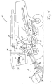
- FIG. 1 In the embodiment of the invention shown in Figure 1 is itself to a self-propelled harvester 1 with a so-called.
- Tangentialoder also Querpounddrehisk 8 and a shaker arranged behind it 21 as a separator. This is a Horde shaker 21 with several shaker stages. Below the shaker 21 there is a cleaning device 23, consisting of several superimposed arranged sieves 24 and a blower 25.
- the invention is but expressly not limited to such combine harvester types.
- the crop is first by means of a reel 3 of the mower 2 in the direction the mower 4 inclined and cut off from mowing blades.
- the Crop is then via a feed screw 5 and an inclined conveyor transported in a feeder channel 6 to the entrance of the threshing 8.
- a loading or Vorbevantertrommel 9 At the entrance of the threshing unit 8 is a loading or Vorbevantertrommel 9 and behind it in Guthnesch a threshing drum 10 with a transversely to Guthnesch - d. H. transverse to the combine longitudinal axis - horizontal axis of rotation.
- a suitably shaped concave 11 Below the threshing cylinder 10 is located itself a suitably shaped concave 11.
- Such a concave 11 usually consists of numerous spaced-apart, in the direction of rotation of the threshing drum 10 semi-circular curved Ribs connected by numerous parallel and transverse webs are.
- the threshing cylinder 10 is at its outer radius with so-called. Dreschleisten equipped (not shown).
- the crop coming from the intake duct 6 is detected by the Vorbeschreibertrommel 9 and then continue from the threshing drum 10 by the between the threshing cylinder 10 and the Threshing basket 11 pulled Dreschspalt pulled. It is by the Dreschleisten threshed the crop, d. H. beaten and / or grated, wherein a grain-chaff mixture through the concave 11 down which is then supplied to the cleaning device 23 to the grains of the admixtures, d. H. Halm and spreader parts to separate.
- the threshed stream of material is then on the turning drum 14 directed to the Horden presentler 21, through which the still in the stream located grains and possibly short straw and chaff are separated.
- the grains, the short straw and the chaff are then also in the Cleaning device 23, in which the grains of short straw and chaff be separated. This is done in such a way that through the sieve openings (Holes, meshes, slots) in the wires 24 by means of the blower 25 wind is blown through, which loosens the guided over the wires 24 crop and for the separation of the specifically lighter chaff and Short straw shares, while the heavy Erntegutkörner through the Screen openings fall.
- the sieves 24 are here partially arranged one above the other, so that the crop is different in different stages is screened.
- the grains passing through all sieves 24 of the cleaning device 23 fall, fall on the collecting and guiding floors and are fed to a grain conveyor screw. They are then of one Elevator 27 transported in a grain tank 28 of the combine 1 and can if necessary, with a tank emptying conveyor 29 on a trolley be reloaded.
- the particles in the cleaning device 23 on the upper of the sieves 24 to reach the rear end are usually heavier particles, d.
- H. Particles containing a grain in which the grain is not completely different from other components of the grain has solved. These shares can be via a further elevator as so-called.
- Botlose be returned to the threshing 8 again.
- the combine harvester 1 has different sensor devices at different locations 7, 22, 26, 30, 31. This includes on the one hand a button 7 in Feeding channel 6, with the layer height H of the crop in the feeder channel. 6 and thus the Emtegut malficient can be measured directly.
- Sensor devices are each baffles with knock sensors 22, 26 at the rear end under the Horden presentler 21 and at the rear end under the upper sieve 24 of the cleaning device 23 the combine harvester as an additional sensor device in the grain tank at the exit the elevator 27, a grain breakage detector 30 which is capable of damaged, d. H. to prove broken grains, and a yield meter 31, which is arranged in the grain elevator 27 to the grain amount to determine.
- All of these sensor devices 7, 22, 26, 30, 31 are provided with a control device 15 connected.
- a control device 15 To this control device 15 is also a user interface 17, for example, with a display 18 and various Keys 19 are connected, with which a driver operate the control device 15 or can program.
- the user interface 17 is located within the cab 30. With the help of the user interface 17 can the driver, for example, specify the harvest conditions and the crop and the optimum crop throughput for these conditions and the respective crop and set the associated optimal machine parameters or machine-proposed optimal parameters.
- the generated by the button 7 in the feeder channel 6 signal SHS is directly proportional to the layer height H in the intake channel 6 and thus proportional to Crop. That of the knock sensor 22 at the rear end of the separator 21 generated signal AVS is substantially proportional to the losses occurring at the separation device 21. Likewise is the signal RVS of the sensor 26 in the cleaning device 23 is a measure of the grain losses at the cleaning device 23.
- the control device 15 is here as a block shown schematically, in which the Erntegut malficient-control device 16 is integrated.
- the control device 15 can in the usual way be constructed of hardware and / or software components.
- this control device 15 comprises one or more processors networked processors, on which appropriate software for control the individual components and the evaluation of the measurement signals implemented is.
- the control device can Signals SHS, AVS, RVS, KBS, KDS received and control commands AB, DB output.
- the Erntegut malficient-control device 16 may, as shown here, designed as a sub-module within the control device 15 be. In principle, this part of the control device but also separately be constructed by the other components of the control device. These components required for the invention can also be used on one in a harvester existing electronic hardware and Software platform (eg the electronic board information system CEBIS the company CLAAS).
- CEBIS electronic board information system
- the crop throughput controller 16 evaluates those of the individual Sensors 4, 22, 26, 30, 31 provided signals EDS, RVS, AVS, KDS, KBS and determined from one of the signals or a combination several signals, for example, based on the ratio of two Signals to each other, the deviations of the current Erntegut besatzes from the optimal target crop throughput to which the machine parameters are optimized were.
- an inventive Combine not necessarily all of these sensors must have.
- the invention may also be, for example can only be realized with a layer height sensor 7 in the crop 6. But most modern combine harvesters are the most diverse ones anyway Sensors, it makes sense, all existing measurement signals in the Emtegut malficient control device to evaluate in order to a possible fast and safe diagnosis.
- the threshing 8 is controlled.
- the control device 15 to a variator (not shown) output a speed command DB, to increase or reduce the threshing drum rotational speed D.
- Figure 3 shows as an example two functions I, II, by which it is specified how the basket distance A is to be set in each case at a certain threshing drum rotational speed.
- the threshing concave spacing A is plotted here above the threshing drum rotational speed D.
- the threshing drum rotational speed D is adjustable between the extreme points D min as the minimum threshing drum rotational speed and D max as the maximum threshing drum rotational speed.
- the threshing concave distance A can be adjusted between the maximum concave spacing A max and the minimum concave spacing A min .
- the hatched area outside is a prohibited area.
- the minimum threshing concave spacing A is still above the mechanically possible concave spacing A mech , at which the concave 11 would rest directly on the threshing drum 10. Furthermore, two areas B A and B D are shown in which the grain breakage risk is increased due to a too short basket distance A or too high a speed D.
- the optimum threshing drum speed D opt and the optimum threshing basket distance A opt should be set.
- the threshing drum rotational speed D and / or the threshing concave distance A is reduced or increased in accordance with the deviations.
- the threshing drum rotational speed D is continuously reduced with decreasing crop throughput and the threshing drum rotational speed D is increased with increasing crop throughput, whereby, of course, the respective limit values D max , D min must be taken into account.
- the two curves I, II show two different possibilities which the adjustment of the concave distance A as a function of the selected threshing drum speed D and thus in dependence on the Deviations of the crop throughput from the target crop throughput occurred could.
- the one process is the loosening of the grains from the ears. This process is essentially influenced by the threshing drum speed D.
- the blow bars of the Threshing drum 10 beat more or less strongly on the straw mat and thus loosen the grains from the ears.
- This process has the Side effect that damages the grains due to the acceleration can be, d. H. that grains break occurs.
- the second process is the Entgrannation or de-stressing. This process is essentially through generates the friction effect in the straw mat. The friction influence is against it again significantly influenced by the basket distance A. This is too Note that too tight a basket can lead to grain damage.
- Curve I applies to cereals where the basket spacing A has a large influence on the threshing process. These are such cereals, at which it is necessary to generate friction over a relatively close wicker position, such as As in barley, in which the awns removed by friction become. For such crops basket distance A should be lower as the crop throughput is continually reduced, d. H. of the Basket distance A is adapted to the height H of Emtengutmatte to the Maintain basic friction.
- the Control even more curves for a variety of specific Erntegutart and / or for different crop characteristics such as be specified the degree of maturity.
- the fruit selection can be within a menu of an electronic on-board information system be determined.
- the respective Harvest types are also assigned to the respective curves, which also automatically by an electronic on-board information system a stored classification table or the like can be done.
- the invention enables a very fast automatic response the threshing unit to temporary throughput changes without consuming to reconfigure all machine parameters.
- the special Benefit of the invention is therefore particularly evident if only temporarily harassable crop properties within the crop stock occur.
- An example of this is a storage board in the field, where the grain is pressed flat on the ground. The harvesting speed must be lowered when driving through this area, so that the crop throughput automatically decreases temporarily.
- Corresponding The type of cereal then fully automatically the threshing drum speed and the basket spacing adjusted to the Erntegut malficient.
- the system is designed so that the driver at any time during a harvesting operation is able to set single or all Manually override machine parameters.
Landscapes
- Life Sciences & Earth Sciences (AREA)
- Environmental Sciences (AREA)
- Harvester Elements (AREA)
- Threshing Machine Elements (AREA)
- Combines (AREA)
Abstract
Description
- 1
- Mähdrescher
- 2
- Mähtisch
- 3
- Haspel
- 4
- Mäheinrichtung
- 5
- Einzugsschnecke
- 6
- Einzugskanal
- 7
- Schichthöhensensor
- 8
- Dreschwerk
- 9
- Vorbeschleunigertrommel
- 10
- Dreschtrommel
- 11
- Dreschkorb
- 12
- Schwenkachse
- 13
- Stellglied
- 14
- Wendetrommel
- 15
- Steuereinrichtung
- 16
- Erntegutdurchsatz-Kontrolleinrichtung
- 17
- Benutzerschnittstelle
- 18
- Display
- 19
- Tasten
- 20
- Wendetrommel
- 21
- Hordenschüttler
- 22
- Sensoreinrichtung
- 23
- Reinigungseinrichtung
- 24
- Sieb
- 25
- Gebläse
- 26
- Sensoreinrichtung
- 27
- Elevator
- 28
- Korntank
- 29
- Tankentleerförderer
- 30
- Kornbruchdetektoreinrichtung
- 31
- Ertragsmessgerät
- A
- Korbabstand
- D
- Dreschtrommeldrehzahl
- H
- Schichthöhe
- AB
- Abstandsbefehl
- DB
- Drehzahlbefehl
- KBS
- Kornbruchsignal
- SHS
- Schichthöhensignal
- AVS
- Abscheideverlustsignal
- RVS
- Reinigungsverlustsignal
- KDS
- Korndurchsatzsignal
Claims (19)
- Verfahren zur Steuerung eines Dreschwerks (8) eines Mähdreschers (1), bei dem bestimmte Parameter (A, D) des Dreschwerks (8) hinsichtlich eines für bestimmte Erntebedingungen festgelegten Soll-Erntegutdurchsatzes auf einen Optimalwert (Aopt, Dopt) eingestellt werden,
dadurch gekennzeichnet, dass automatisch eine Abweichung des aktuellen Erntegutdurchsatzes vom Soll-Erntegutdurchsatz erkannt und daraufhin zumindest ein Dreschwerkparameter (A, D) zur Anpassung an den aktuellen Erntegutdurchsatz verstellt wird. - Verfahren nach Anspruch 1, dadurch gekennzeichnet, dass das Dreschwerk (8) durch Verstellung einer Dreschtrommeldrehzahl (D) und/oder eines Dreschkorbabstands (A) an den aktuellen Erntegutdurchsatz angepasst wird.
- Verfahren nach Anspruch 2, dadurch gekennzeichnet, dass mit abnehmendem Emtegutdurchsatz (E) die Dreschtrommeldrehzahl (D) verringert wird.
- Verfahren nach Anspruch 2 oder 3, dadurch gekennzeichnet, dass mit abnehmendem Erntegutdurchsatz (E) der Dreschkorbabstand (A) verringert wird.
- Verfahren nach einem der Ansprüche 2 bis 4, dadurch gekennzeichnet, dass der Dreschkorbabstand (A) gemäß einer vorgegebenen Funktion (I, II) in Abhängigkeit von der aktuellen Dreschtrommeldrehzahl (D) verstellt wird.
- Verfahren nach einem der Ansprüche 2 bis 5, dadurch gekennzeichnet, dass die Dreschtrommeldrehzahl (D) und/oder der Dreschkorbabstand (A) in Abhängigkeit von einer Ernteguteigenschaft verstellt werden.
- Verfahren nach einem der Ansprüche 1 bis 6, dadurch gekennzeichnet, dass erst dann ein Dreschwerkparameter (A, D) verstellt wird, wenn der aktuelle Erntegutdurchsatz um einen bestimmten Schwellwert und/oder eine bestimmte erste Zeitspanne vom Soll-Erntegutdurchsatz abweicht.
- Verfahren nach einem der Ansprüche 1 bis 7, dadurch gekennzeichnet, dass der aktuelle Erntegutdurchsatz in einem Ernteguteinzug (6) gemessen wird.
- Verfahren nach einem der Ansprüche 1 bis 8, dadurch gekennzeichnet, dass eine Abweichung des aktuellen Erntegutdurchsatzes vom Soll-Erntegutdurchsatz anhand einer Verlustmenge an einem Ausgang einer Abscheideeinrichtung (21) und/oder an einem Ausgang einer Reinigungseinrichtung (23) bestimmt wird.
- Verfahren nach einem der Ansprüche 1 bis 9, dadurch gekennzeichnet, dass eine Abweichung des aktuelle Erntegutdurchsatzes vom Soll-Erntegutdurchsatz anhand eines Bruchkornanteils bestimmt wird.
- Verfahren nach einem der Ansprüche 1 bis 10, dadurch gekennzeichnet, dass eine Abweichung des aktuellen Erntegutdurchsatzes vom Soll-Erntegutdurchsatz durch Messung eines Drehmoments an einer Antriebswelle und/oder durch Messung eines Abtriebsmoments eines Antriebsmotors ermittelt wird.
- Verfahren nach einem der Ansprüche 1 bis 11, dadurch gekennzeichnet, dass ein verstellter Dreschwerkparameter (A, D) automatisch auf den Optimalwert (Aopt, Dopt) zurückgestellt wird, wenn der aktuelle Erntegutdurchsatz wieder dem Soll-Erntegutdurchsatz entspricht oder um weniger als einen bestimmten Schwellwert vom Soll-Erntegutdurchsatz abweicht.
- Verfahren nach einem der Ansprüche 1 bis 12, dadurch gekennzeichnet, dass nach Ablauf einer bestimmten zweiten Zeitspanne, in welcher der Soll-Erntegutdurchsatz nicht erreicht wird oder um mehr als einen bestimmten Schwellwert davon abweicht, automatisch eine Neujustage weiterer einstellbarer Parameter von verschiedenen Arbeitsorganen des Mähdreschers (1) erfolgt und/oder einem Bediener angeboten wird, diese einstellbaren Parameter optimal hinsichtlich des aktuellen Emtegutdurchsatzes als neuen Soll-Erntegutdurchsatz einzustellen.
- Mähdrescher (1) mit einem Dreschwerk (8)
und einer Steuereinrichtung (15), um bestimmte Parameter (A, D) des Dreschwerks (8) hinsichtlich eines für bestimmte Erntebedingungen festgelegten Soll-Erntegutdurchsatzes auf einen Optimalwert (Aopt, Dopt) einzustellen,
dadurch gekennzeichnet, dass die Steuereinrichtung (15) eine Erntegutdurchsatz-Kontrolleinrichtung (16) umfasst, welche automatisch eine Abweichung des aktuellen Erntegutdurchsatzes vom Soll-Erntegutdurchsatz erkennt, und die Steuereinrichtung (15) derart ausgebildet ist, dass sie bei einer solchen Abweichung zumindest einen Dreschwerkparameter (A, D) zur Anpassung an den aktuellen Erntegutdurchsatz verstellt. - Mähdrescher nach Anspruch 14, gekennzeichnet durch eine in einem Ernteguteinzug (6) angeordnete Sensoreinrichtung (7) zur Ermittlung des aktuellen Erntegutdurchsatzes.
- Mähdrescher nach Anspruch 15, dadurch gekennzeichnet, dass die Sensoreinrichtung (7) einen Taster (7) zur Ermittlung einer Erntegutschichthöhe (H) im Ernteguteinzug (6) umfasst.
- Mähdrescher nach einem der Ansprüche 14 bis 16, gekennzeichnet durch einen an einem Ausgang einer Abscheideeinrichtung (21) und/oder einen an einem Ausgang einer Reinigungseinrichtung (23) angeordneten Verlustmengensensor (22, 26).
- Mähdrescher nach einem der Ansprüche 14 bis 17, gekennzeichnet durch eine Bruchkom-Sensoreinrichtung (30).
- Mähdrescher nach einem der Ansprüche 14 bis 18, gekennzeichnet durch eine Messeinrichtung zur Ermittlung eines Drehmoments an einer Antriebswelle und/oder eines Abtriebsmoments eines Antriebsmotors.
Applications Claiming Priority (2)
| Application Number | Priority Date | Filing Date | Title |
|---|---|---|---|
| DE10327758 | 2003-06-18 | ||
| DE10327758A DE10327758A1 (de) | 2003-06-18 | 2003-06-18 | Verfahren zur Steuerung eines Dreschwerks eines Mähdreschers |
Publications (2)
| Publication Number | Publication Date |
|---|---|
| EP1493318A1 true EP1493318A1 (de) | 2005-01-05 |
| EP1493318B1 EP1493318B1 (de) | 2016-09-28 |
Family
ID=33426773
Family Applications (1)
| Application Number | Title | Priority Date | Filing Date |
|---|---|---|---|
| EP04012966.0A Expired - Lifetime EP1493318B1 (de) | 2003-06-18 | 2004-06-02 | Verfahren zur Steuerung eines Dreschwerks eines Mähdreschers |
Country Status (4)
| Country | Link |
|---|---|
| US (1) | US7001267B2 (de) |
| EP (1) | EP1493318B1 (de) |
| DE (1) | DE10327758A1 (de) |
| RU (1) | RU2349074C2 (de) |
Cited By (3)
| Publication number | Priority date | Publication date | Assignee | Title |
|---|---|---|---|---|
| CN103749075A (zh) * | 2014-01-02 | 2014-04-30 | 洛阳理工学院 | 一种用于联合收获机的控制系统 |
| CN105340465A (zh) * | 2007-07-31 | 2016-02-24 | 株式会社久保田 | 联合收割机 |
| EP3023001A1 (de) * | 2014-10-31 | 2016-05-25 | Deere & Company | Selbsteinstellendes konkavspaltsystem |
Families Citing this family (33)
| Publication number | Priority date | Publication date | Assignee | Title |
|---|---|---|---|---|
| DE102005014278A1 (de) * | 2005-03-24 | 2006-10-05 | Claas Selbstfahrende Erntemaschinen Gmbh | Verfahren zur Ermittlung eines Ziel-Einstellwerts |
| DE102005026159A1 (de) * | 2005-06-06 | 2007-01-25 | Claas Selbstfahrende Erntemaschinen Gmbh | Verfahren zur Steuerung einer Erntemaschine |
| US7306513B2 (en) * | 2005-11-30 | 2007-12-11 | Deere & Company | Leveling by over-compensation |
| DE102007029218A1 (de) * | 2007-06-22 | 2008-12-24 | Claas Selbstfahrende Erntemaschinen Gmbh | Selbstfahrende landwirtschaftliche Erntemaschine mit Verlustmesseinrichtung |
| US8157629B2 (en) * | 2008-03-14 | 2012-04-17 | Deere & Company | Concave suspension for a threshing section in a harvesting machine |
| US7857690B2 (en) * | 2008-03-14 | 2010-12-28 | Deere & Company | Concave suspension control system and method for a threshing section in a harvesting machine |
| US20100010713A1 (en) | 2008-07-10 | 2010-01-14 | Sheidler Alan D | Threshing rotor power monitor |
| BE1018875A3 (nl) * | 2009-09-01 | 2011-10-04 | Cnh Belgium Nv | Landbouwmachine met variabele toerentalregeling. |
| US20110320087A1 (en) * | 2010-06-29 | 2011-12-29 | Farley Herbert M | Remote control adjustable threshing cage vane system and method |
| US10318138B2 (en) | 2011-03-11 | 2019-06-11 | Intelligent Agricultural Solutions Llc | Harvesting machine capable of automatic adjustment |
| US9324197B2 (en) | 2011-03-11 | 2016-04-26 | Intelligent Agricultural Soultions | Method and system for managing the hand-off between control terminals |
| US9474208B2 (en) * | 2011-11-15 | 2016-10-25 | Appareo Systems, Llc | System and method for determining material yield and/or loss from a harvesting machine using acoustic sensors |
| US9330062B2 (en) | 2011-03-11 | 2016-05-03 | Intelligent Agricultural Solutions, Llc | Vehicle control and gateway module |
| US10321624B2 (en) | 2011-03-11 | 2019-06-18 | Intelligent Agriculture Solutions LLC | Air seeder manifold system |
| US9631964B2 (en) | 2011-03-11 | 2017-04-25 | Intelligent Agricultural Solutions, Llc | Acoustic material flow sensor |
| US9629308B2 (en) | 2011-03-11 | 2017-04-25 | Intelligent Agricultural Solutions, Llc | Harvesting machine capable of automatic adjustment |
| RU2493691C1 (ru) * | 2012-04-10 | 2013-09-27 | Государственное научное учреждение Северо-Западный научно-исследовательский институт механизации и электрификации сельского хозяйства Российской академии сельскохозяйственных наук (ГНУ СЗНИИМЭСХ Россельхозакадемии) | Молотильно-сепарирующее устройство (варианты) |
| US8820039B2 (en) * | 2012-08-27 | 2014-09-02 | Cnh Industrial America Llc | Cornhead crop loss detection |
| WO2015156774A1 (en) * | 2014-04-08 | 2015-10-15 | Cnh Industrial America Llc | Harvester elevator and system for increased autonomy |
| US9699970B2 (en) | 2013-09-19 | 2017-07-11 | Cnh Industrial America Llc | Combine side-shake cleaning control system |
| BE1021889B1 (nl) * | 2014-05-28 | 2016-01-25 | Cnh Industrial Belgium Nv | Systeem en werkwijze voor het regelen van een reinigingszeef in een oogstmachine |
| RU2564865C1 (ru) * | 2014-06-06 | 2015-10-10 | Федеральное государственное бюджетное образовательное учреждение высшего профессионального образования Новосибирский государственный аграрный университет | Способ регулирования загрузки зерноуборочного комбайна и устройство для его осуществления |
| US10085379B2 (en) | 2014-09-12 | 2018-10-02 | Appareo Systems, Llc | Grain quality sensor |
| JP6675843B2 (ja) * | 2015-09-02 | 2020-04-08 | 株式会社クボタ | コンバイン |
| US10512217B2 (en) | 2017-08-23 | 2019-12-24 | Deere & Company | Metering flow of grain to a cleaning device |
| DE102018103373A1 (de) * | 2018-02-15 | 2019-08-22 | Claas Selbstfahrende Erntemaschinen Gmbh | Mähdrescher sowie Verfahren zu dessen Betrieb |
| DE102018212075A1 (de) * | 2018-07-19 | 2020-01-23 | Deere & Company | Mähdrescher mit einem Schrägförderer mit aktorisch verstellbarer, unterer Umlenkwalze |
| US11013175B2 (en) * | 2018-07-26 | 2021-05-25 | Deere & Company | Grain loss apparatus for a grain harvesting vehicle |
| DE102019119106A1 (de) * | 2019-07-15 | 2021-01-21 | Claas Selbstfahrende Erntemaschinen Gmbh | Verfahren zur Abarbeitung eines landwirtschaftlichen Ernteprozesses |
| EP4068947A4 (de) * | 2019-12-04 | 2024-04-03 | Monsanto Technology LLC | Mähdrescher zum verwenden beim ernten von mais und zugehörige verfahren |
| US11510369B2 (en) * | 2020-03-10 | 2022-11-29 | Deere & Company | Systems and methods for automated concave leveling of combine harvester |
| EP3971775A1 (de) | 2020-09-16 | 2022-03-23 | CLAAS Selbstfahrende Erntemaschinen GmbH | Verfahren zur bestimmung eines von einer betriebssituation einer landwirtschaftlichen arbeitsmaschine abhängigen betriebsparameters als klassifizierungsaufgabe |
| US12593751B2 (en) * | 2022-10-11 | 2026-04-07 | Cnh Industrial America Llc | Agricultural system and method for monitoring feeder throughput of a harvester |
Citations (4)
| Publication number | Priority date | Publication date | Assignee | Title |
|---|---|---|---|---|
| US3606742A (en) * | 1969-04-05 | 1971-09-21 | Franz Wieneke | Arrangement for the automatic control of the threshing process on combine harvesters |
| US4348855A (en) * | 1980-09-22 | 1982-09-14 | International Harvester Company | Crop damage responsive control of rotor speed |
| GB2107489A (en) * | 1981-09-09 | 1983-04-27 | Rds Farm Electronics Limited | Automatic speed control of combine harvesters |
| DE19800238C1 (de) * | 1998-01-07 | 1999-08-26 | Claas Selbstfahr Erntemasch | System zur Einstellung einer selbstfahrenden Erntemaschine |
Family Cites Families (14)
| Publication number | Priority date | Publication date | Assignee | Title |
|---|---|---|---|---|
| US4337611A (en) * | 1980-12-10 | 1982-07-06 | Purdue Research Foundation | Automatic control of a combine threshing cylinder and feeder conveyor |
| US4527241A (en) * | 1982-08-30 | 1985-07-02 | Sperry Corporation | Automatic combine harvester adjustment system |
| SU1243649A2 (ru) * | 1984-09-12 | 1986-07-15 | Сибирский научно-исследовательский институт механизации и электрификации сельского хозяйства | Устройство автоматического регулировани загрузки зерноуборочного комбайна |
| EP0775612B1 (de) * | 1993-06-28 | 2003-09-24 | CNH Belgium N.V. | Steuerungsverfahren für einen selbstangetriebenen Mähdrescher |
| DE4341834C1 (de) * | 1993-12-08 | 1995-04-20 | Claas Ohg | Landmaschine, insbesondere Mähdrescher, mit Multiprozessor-Leitvorrichtung |
| DE4431824C1 (de) * | 1994-09-07 | 1996-05-02 | Claas Ohg | Mähdrescherbetrieb mit Betriebsdatenkataster |
| AU753192B2 (en) | 1998-06-29 | 2002-10-10 | Deere & Company | Optoelectronic apparatus for detecting damaged grain |
| DE19921466A1 (de) * | 1999-05-08 | 2000-11-09 | Deere & Co | Einrichtung zum Regeln der Vortriebsgeschwindigkeit einer Erntemaschine mit unscharfer Logik |
| US6475081B2 (en) * | 2001-03-20 | 2002-11-05 | Deere & Company | Throughput control for combines having a variable torque sensing drive |
| US6553300B2 (en) * | 2001-07-16 | 2003-04-22 | Deere & Company | Harvester with intelligent hybrid control system |
| DE10147733A1 (de) * | 2001-09-27 | 2003-04-10 | Claas Selbstfahr Erntemasch | Verfahren und Vorrichtung zur Ermittlung einer Erntemaschineneinstellung |
| US6834484B2 (en) * | 2001-12-18 | 2004-12-28 | Deere & Company | Automatic control initiation for a harvester |
| US6726559B2 (en) * | 2002-05-14 | 2004-04-27 | Deere & Company | Harvester with control system considering operator feedback |
| US6761630B1 (en) * | 2003-02-10 | 2004-07-13 | Case, Llc | Method of operation of a sieve adjustment control system for an agricultural combine |
-
2003
- 2003-06-18 DE DE10327758A patent/DE10327758A1/de not_active Withdrawn
-
2004
- 2004-06-02 EP EP04012966.0A patent/EP1493318B1/de not_active Expired - Lifetime
- 2004-06-16 US US10/869,240 patent/US7001267B2/en not_active Expired - Lifetime
- 2004-06-16 RU RU2004118111/12A patent/RU2349074C2/ru active
Patent Citations (4)
| Publication number | Priority date | Publication date | Assignee | Title |
|---|---|---|---|---|
| US3606742A (en) * | 1969-04-05 | 1971-09-21 | Franz Wieneke | Arrangement for the automatic control of the threshing process on combine harvesters |
| US4348855A (en) * | 1980-09-22 | 1982-09-14 | International Harvester Company | Crop damage responsive control of rotor speed |
| GB2107489A (en) * | 1981-09-09 | 1983-04-27 | Rds Farm Electronics Limited | Automatic speed control of combine harvesters |
| DE19800238C1 (de) * | 1998-01-07 | 1999-08-26 | Claas Selbstfahr Erntemasch | System zur Einstellung einer selbstfahrenden Erntemaschine |
Cited By (6)
| Publication number | Priority date | Publication date | Assignee | Title |
|---|---|---|---|---|
| CN105340465A (zh) * | 2007-07-31 | 2016-02-24 | 株式会社久保田 | 联合收割机 |
| CN105340464A (zh) * | 2007-07-31 | 2016-02-24 | 株式会社久保田 | 联合收割机 |
| CN103749075A (zh) * | 2014-01-02 | 2014-04-30 | 洛阳理工学院 | 一种用于联合收获机的控制系统 |
| CN103749075B (zh) * | 2014-01-02 | 2015-11-18 | 洛阳理工学院 | 一种用于联合收获机的控制系统 |
| EP3023001A1 (de) * | 2014-10-31 | 2016-05-25 | Deere & Company | Selbsteinstellendes konkavspaltsystem |
| US9980435B2 (en) | 2014-10-31 | 2018-05-29 | Deere & Company | Self adjusting concave clearance system |
Also Published As
| Publication number | Publication date |
|---|---|
| RU2004118111A (ru) | 2005-12-10 |
| RU2349074C2 (ru) | 2009-03-20 |
| US7001267B2 (en) | 2006-02-21 |
| US20040259610A1 (en) | 2004-12-23 |
| DE10327758A1 (de) | 2005-01-05 |
| EP1493318B1 (de) | 2016-09-28 |
Similar Documents
| Publication | Publication Date | Title |
|---|---|---|
| EP1493318B1 (de) | Verfahren zur Steuerung eines Dreschwerks eines Mähdreschers | |
| EP3662741B2 (de) | Landwirtschaftliche arbeitsmaschine sowie verfahren zum betreiben einer landwirtschaftlichen arbeitsmaschine | |
| EP1731017B1 (de) | Verfahren zur Steuerung einer Erntemaschine | |
| EP2042019B1 (de) | Landwirtschaftliches Arbeitsfahrzeug | |
| EP3533315B2 (de) | Feldhäcksler und verfahren zum betreiben eines feldhäckslers | |
| EP1752037B1 (de) | Verfahren zum Überladen von Erntegut | |
| EP1543712B1 (de) | Verfahren und Vorrichtung zur Regelung von Arbeitsorganen eines Mähdreschers | |
| EP1297733B2 (de) | Verfahren und Vorrichtung zur Ermittlung einer Erntemaschineneinstellung | |
| DE602004005553T2 (de) | System zum Ausstossen von Ernteresten aus einem Mähdrescher | |
| EP2837280B1 (de) | Mähdrescher mit einer Häckselvorrichtung | |
| EP1704767A1 (de) | Verfahren zur Ermittlung eines Ziel-Einstellwertes | |
| EP1419687B1 (de) | Verfahren zur Steuerung der Fahrgeschwindigkeit einer Erntemaschine | |
| EP4154699B1 (de) | Landwirtschaftliche arbeitsmaschine mit kennfeldsteuerung | |
| EP1856966A1 (de) | Verfahren und Vorrichtung zum Betreiben einer Erntegutzerkleinerungs- und -verteilvorrichtung | |
| DE102024103608A1 (de) | Erntegutzustandskategorisierungssystem und -verfahren | |
| EP1396184B1 (de) | Vorrichtung zum Zerkleinern von landwirtschaftlichem Erntegut | |
| EP1321024B1 (de) | Verfahren und Vorrichtung zur Optimierung des Betriebs eines landwirtschaftlichen Fahrzeugs | |
| EP4497319A1 (de) | Steuerungsvorrichtung zur ansteuerung eines selbstfahrenden mähdreschers | |
| EP1470749B1 (de) | Dresch-/Separator-System | |
| EP4154700A1 (de) | Erntemaschine mit bandschneidwerk | |
| EP4154697A1 (de) | Fahrerassistenzsystem einer erntemaschine mit bandschneidwerk | |
| EP1576869B1 (de) | Messvorrichtung zur Messung von Oberflächenfeuchte | |
| DE20302925U1 (de) | Vorrichtung zum Trennen eines Erntegutstroms | |
| DE102024102470A1 (de) | System und Verfahren zur indirekten Leistungs- und Drehmomentbestimmung | |
| DE102024103607A1 (de) | Dresch- und Häckslerleistungsbeziehungsidentifikationssystem und -verfahren |
Legal Events
| Date | Code | Title | Description |
|---|---|---|---|
| PUAI | Public reference made under article 153(3) epc to a published international application that has entered the european phase |
Free format text: ORIGINAL CODE: 0009012 |
|
| AK | Designated contracting states |
Kind code of ref document: A1 Designated state(s): AT BE BG CH CY CZ DE DK EE ES FI FR GB GR HU IE IT LI LU MC NL PL PT RO SE SI SK TR |
|
| AX | Request for extension of the european patent |
Extension state: AL HR LT LV MK |
|
| 17P | Request for examination filed |
Effective date: 20050705 |
|
| AKX | Designation fees paid |
Designated state(s): AT BE BG CH CY CZ DE DK EE ES FI FR GB GR HU IE IT LI LU MC NL PL PT RO SE SI SK TR |
|
| 17Q | First examination report despatched |
Effective date: 20090202 |
|
| GRAP | Despatch of communication of intention to grant a patent |
Free format text: ORIGINAL CODE: EPIDOSNIGR1 |
|
| INTG | Intention to grant announced |
Effective date: 20160511 |
|
| GRAP | Despatch of communication of intention to grant a patent |
Free format text: ORIGINAL CODE: EPIDOSNIGR1 |
|
| INTG | Intention to grant announced |
Effective date: 20160610 |
|
| GRAS | Grant fee paid |
Free format text: ORIGINAL CODE: EPIDOSNIGR3 |
|
| GRAA | (expected) grant |
Free format text: ORIGINAL CODE: 0009210 |
|
| AK | Designated contracting states |
Kind code of ref document: B1 Designated state(s): AT BE BG CH CY CZ DE DK EE ES FI FR GB GR HU IE IT LI LU MC NL PL PT RO SE SI SK TR |
|
| REG | Reference to a national code |
Ref country code: GB Ref legal event code: FG4D Free format text: NOT ENGLISH |
|
| REG | Reference to a national code |
Ref country code: CH Ref legal event code: EP |
|
| REG | Reference to a national code |
Ref country code: AT Ref legal event code: REF Ref document number: 831968 Country of ref document: AT Kind code of ref document: T Effective date: 20161015 |
|
| REG | Reference to a national code |
Ref country code: IE Ref legal event code: FG4D Free format text: LANGUAGE OF EP DOCUMENT: GERMAN |
|
| REG | Reference to a national code |
Ref country code: DE Ref legal event code: R096 Ref document number: 502004015319 Country of ref document: DE |
|
| RAP2 | Party data changed (patent owner data changed or rights of a patent transferred) |
Owner name: CLAAS SELBSTFAHRENDE ERNTEMASCHINEN GMBH |
|
| PG25 | Lapsed in a contracting state [announced via postgrant information from national office to epo] |
Ref country code: FI Free format text: LAPSE BECAUSE OF FAILURE TO SUBMIT A TRANSLATION OF THE DESCRIPTION OR TO PAY THE FEE WITHIN THE PRESCRIBED TIME-LIMIT Effective date: 20160928 |
|
| REG | Reference to a national code |
Ref country code: NL Ref legal event code: MP Effective date: 20160928 |
|
| PG25 | Lapsed in a contracting state [announced via postgrant information from national office to epo] |
Ref country code: SE Free format text: LAPSE BECAUSE OF FAILURE TO SUBMIT A TRANSLATION OF THE DESCRIPTION OR TO PAY THE FEE WITHIN THE PRESCRIBED TIME-LIMIT Effective date: 20160928 Ref country code: NL Free format text: LAPSE BECAUSE OF FAILURE TO SUBMIT A TRANSLATION OF THE DESCRIPTION OR TO PAY THE FEE WITHIN THE PRESCRIBED TIME-LIMIT Effective date: 20160928 Ref country code: GR Free format text: LAPSE BECAUSE OF FAILURE TO SUBMIT A TRANSLATION OF THE DESCRIPTION OR TO PAY THE FEE WITHIN THE PRESCRIBED TIME-LIMIT Effective date: 20161229 |
|
| PG25 | Lapsed in a contracting state [announced via postgrant information from national office to epo] |
Ref country code: EE Free format text: LAPSE BECAUSE OF FAILURE TO SUBMIT A TRANSLATION OF THE DESCRIPTION OR TO PAY THE FEE WITHIN THE PRESCRIBED TIME-LIMIT Effective date: 20160928 Ref country code: RO Free format text: LAPSE BECAUSE OF FAILURE TO SUBMIT A TRANSLATION OF THE DESCRIPTION OR TO PAY THE FEE WITHIN THE PRESCRIBED TIME-LIMIT Effective date: 20160928 |
|
| PG25 | Lapsed in a contracting state [announced via postgrant information from national office to epo] |
Ref country code: BG Free format text: LAPSE BECAUSE OF FAILURE TO SUBMIT A TRANSLATION OF THE DESCRIPTION OR TO PAY THE FEE WITHIN THE PRESCRIBED TIME-LIMIT Effective date: 20161228 Ref country code: PL Free format text: LAPSE BECAUSE OF FAILURE TO SUBMIT A TRANSLATION OF THE DESCRIPTION OR TO PAY THE FEE WITHIN THE PRESCRIBED TIME-LIMIT Effective date: 20160928 Ref country code: SK Free format text: LAPSE BECAUSE OF FAILURE TO SUBMIT A TRANSLATION OF THE DESCRIPTION OR TO PAY THE FEE WITHIN THE PRESCRIBED TIME-LIMIT Effective date: 20160928 Ref country code: CZ Free format text: LAPSE BECAUSE OF FAILURE TO SUBMIT A TRANSLATION OF THE DESCRIPTION OR TO PAY THE FEE WITHIN THE PRESCRIBED TIME-LIMIT Effective date: 20160928 Ref country code: ES Free format text: LAPSE BECAUSE OF FAILURE TO SUBMIT A TRANSLATION OF THE DESCRIPTION OR TO PAY THE FEE WITHIN THE PRESCRIBED TIME-LIMIT Effective date: 20160928 Ref country code: PT Free format text: LAPSE BECAUSE OF FAILURE TO SUBMIT A TRANSLATION OF THE DESCRIPTION OR TO PAY THE FEE WITHIN THE PRESCRIBED TIME-LIMIT Effective date: 20170130 |
|
| REG | Reference to a national code |
Ref country code: DE Ref legal event code: R097 Ref document number: 502004015319 Country of ref document: DE |
|
| PG25 | Lapsed in a contracting state [announced via postgrant information from national office to epo] |
Ref country code: DK Free format text: LAPSE BECAUSE OF FAILURE TO SUBMIT A TRANSLATION OF THE DESCRIPTION OR TO PAY THE FEE WITHIN THE PRESCRIBED TIME-LIMIT Effective date: 20160928 |
|
| PLBE | No opposition filed within time limit |
Free format text: ORIGINAL CODE: 0009261 |
|
| STAA | Information on the status of an ep patent application or granted ep patent |
Free format text: STATUS: NO OPPOSITION FILED WITHIN TIME LIMIT |
|
| 26N | No opposition filed |
Effective date: 20170629 |
|
| PG25 | Lapsed in a contracting state [announced via postgrant information from national office to epo] |
Ref country code: SI Free format text: LAPSE BECAUSE OF FAILURE TO SUBMIT A TRANSLATION OF THE DESCRIPTION OR TO PAY THE FEE WITHIN THE PRESCRIBED TIME-LIMIT Effective date: 20160928 |
|
| PG25 | Lapsed in a contracting state [announced via postgrant information from national office to epo] |
Ref country code: MC Free format text: LAPSE BECAUSE OF FAILURE TO SUBMIT A TRANSLATION OF THE DESCRIPTION OR TO PAY THE FEE WITHIN THE PRESCRIBED TIME-LIMIT Effective date: 20160928 |
|
| REG | Reference to a national code |
Ref country code: CH Ref legal event code: PL |
|
| GBPC | Gb: european patent ceased through non-payment of renewal fee |
Effective date: 20170602 |
|
| REG | Reference to a national code |
Ref country code: IE Ref legal event code: MM4A |
|
| REG | Reference to a national code |
Ref country code: FR Ref legal event code: ST Effective date: 20180228 |
|
| REG | Reference to a national code |
Ref country code: DE Ref legal event code: R084 Ref document number: 502004015319 Country of ref document: DE |
|
| PG25 | Lapsed in a contracting state [announced via postgrant information from national office to epo] |
Ref country code: LI Free format text: LAPSE BECAUSE OF NON-PAYMENT OF DUE FEES Effective date: 20170630 Ref country code: IE Free format text: LAPSE BECAUSE OF NON-PAYMENT OF DUE FEES Effective date: 20170602 Ref country code: GB Free format text: LAPSE BECAUSE OF NON-PAYMENT OF DUE FEES Effective date: 20170602 Ref country code: LU Free format text: LAPSE BECAUSE OF NON-PAYMENT OF DUE FEES Effective date: 20170602 Ref country code: CH Free format text: LAPSE BECAUSE OF NON-PAYMENT OF DUE FEES Effective date: 20170630 |
|
| PG25 | Lapsed in a contracting state [announced via postgrant information from national office to epo] |
Ref country code: FR Free format text: LAPSE BECAUSE OF NON-PAYMENT OF DUE FEES Effective date: 20170630 |
|
| PGFP | Annual fee paid to national office [announced via postgrant information from national office to epo] |
Ref country code: DE Payment date: 20180425 Year of fee payment: 15 |
|
| REG | Reference to a national code |
Ref country code: AT Ref legal event code: MM01 Ref document number: 831968 Country of ref document: AT Kind code of ref document: T Effective date: 20170602 |
|
| PG25 | Lapsed in a contracting state [announced via postgrant information from national office to epo] |
Ref country code: AT Free format text: LAPSE BECAUSE OF NON-PAYMENT OF DUE FEES Effective date: 20170602 |
|
| PG25 | Lapsed in a contracting state [announced via postgrant information from national office to epo] |
Ref country code: HU Free format text: LAPSE BECAUSE OF FAILURE TO SUBMIT A TRANSLATION OF THE DESCRIPTION OR TO PAY THE FEE WITHIN THE PRESCRIBED TIME-LIMIT; INVALID AB INITIO Effective date: 20040602 |
|
| PG25 | Lapsed in a contracting state [announced via postgrant information from national office to epo] |
Ref country code: CY Free format text: LAPSE BECAUSE OF NON-PAYMENT OF DUE FEES Effective date: 20160928 |
|
| REG | Reference to a national code |
Ref country code: DE Ref legal event code: R119 Ref document number: 502004015319 Country of ref document: DE |
|
| PG25 | Lapsed in a contracting state [announced via postgrant information from national office to epo] |
Ref country code: TR Free format text: LAPSE BECAUSE OF FAILURE TO SUBMIT A TRANSLATION OF THE DESCRIPTION OR TO PAY THE FEE WITHIN THE PRESCRIBED TIME-LIMIT Effective date: 20160928 |
|
| PG25 | Lapsed in a contracting state [announced via postgrant information from national office to epo] |
Ref country code: DE Free format text: LAPSE BECAUSE OF NON-PAYMENT OF DUE FEES Effective date: 20200101 |
|
| P01 | Opt-out of the competence of the unified patent court (upc) registered |
Effective date: 20230512 |
|
| PGFP | Annual fee paid to national office [announced via postgrant information from national office to epo] |
Ref country code: BE Payment date: 20230620 Year of fee payment: 20 |
|
| PGFP | Annual fee paid to national office [announced via postgrant information from national office to epo] |
Ref country code: IT Payment date: 20230623 Year of fee payment: 20 |
|
| REG | Reference to a national code |
Ref country code: BE Ref legal event code: MK Effective date: 20240602 |