EP1492007B1 - System und Verfahren zur Steuerung eines Rechners mit verschienen Betriebsmodi - Google Patents
System und Verfahren zur Steuerung eines Rechners mit verschienen Betriebsmodi Download PDFInfo
- Publication number
- EP1492007B1 EP1492007B1 EP20040076739 EP04076739A EP1492007B1 EP 1492007 B1 EP1492007 B1 EP 1492007B1 EP 20040076739 EP20040076739 EP 20040076739 EP 04076739 A EP04076739 A EP 04076739A EP 1492007 B1 EP1492007 B1 EP 1492007B1
- Authority
- EP
- European Patent Office
- Prior art keywords
- operation mode
- mode
- computer
- sampling point
- modes
- Prior art date
- Legal status (The legal status is an assumption and is not a legal conclusion. Google has not performed a legal analysis and makes no representation as to the accuracy of the status listed.)
- Expired - Lifetime
Links
Images


Classifications
-
- G—PHYSICS
- G06—COMPUTING OR CALCULATING; COUNTING
- G06F—ELECTRIC DIGITAL DATA PROCESSING
- G06F11/00—Error detection; Error correction; Monitoring
- G06F11/07—Responding to the occurrence of a fault, e.g. fault tolerance
- G06F11/14—Error detection or correction of the data by redundancy in operation
- G06F11/1497—Details of time redundant execution on a single processing unit
-
- G—PHYSICS
- G06—COMPUTING OR CALCULATING; COUNTING
- G06F—ELECTRIC DIGITAL DATA PROCESSING
- G06F11/00—Error detection; Error correction; Monitoring
- G06F11/07—Responding to the occurrence of a fault, e.g. fault tolerance
- G06F11/0703—Error or fault processing not based on redundancy, i.e. by taking additional measures to deal with the error or fault not making use of redundancy in operation, in hardware, or in data representation
- G06F11/0751—Error or fault detection not based on redundancy
- G06F11/0754—Error or fault detection not based on redundancy by exceeding limits
- G06F11/0757—Error or fault detection not based on redundancy by exceeding limits by exceeding a time limit, i.e. time-out, e.g. watchdogs
Definitions
- the present invention relates to a system and method of controlling a computer supporting multiple operation modes, and more particularly to a system and method of operating a computer capable of operating in multiple operation modes and controlling the operation of such computer by a mode controller and a watchdog monitor module.
- the operating system of a computer can execute numerous multimedia software, such as music player, video player, TV player, radio receiver application, image capturer and explorer, and video/audio recording programs, and perform associated multimedia functions using related peripheral appliances and corresponding drivers.
- multimedia software such as music player, video player, TV player, radio receiver application, image capturer and explorer, and video/audio recording programs, and perform associated multimedia functions using related peripheral appliances and corresponding drivers.
- conventional configurations of a computer provide a fixed number of specific control means corresponding to available operation modes.
- the computer can execute related software and operates in the designated operation mode by activating corresponding control means.
- Conventional methods are simple, however, the number of the control means available for use in a computer is limited and must be preset in advance, such that extension of the maneuverability of the computer is limited.
- the manufacturer of the computer must produce related hardware to support the computer for operating in multiple operation modes, thereby increasing the manufacturing cost.
- US 2002/0089819 discloses a portable information processing apparatus having an operation element which can be rotated and pushed in to execute a selected application.
- a preferred embodiment of the present invention provides a system and method for controlling a computer supporting multiple operation modes according to claims 1 and 8 respectively.
- the system according to the present invention includes a mode controller for generating a combination of electric potentials on two connection terminals, and an additional microprocessor.
- the additional microprocessor includes a storage module including a mode list recording a plurality of operation modes, and a pointer for designating one of the operation modes in the mode list as a first operation mode for the computer.
- the additional microprocessor also includes a detection module to detect the combination of the electric potentials at a first sampling point, and determines a shift direction of the mode controller according thereto.
- the additional microprocessor further includes a control module to select a second operation mode adjacent to the first operation mode in the mode list according to the shift direction, check the disparity between the first operation mode and the second operation mode, provide a control signal to the computer according to the check result, direct the computer to reboot or execute an application specific to the second operation mode, and subsequently enable the computer to operate in the second operation mode.
- the method of controlling the computer supporting multiple operation modes uses an additional microprocessor to detect a combination of the electric potentials triggered by a mode controller at a first sampling point, and then determines a shift direction of the mode controller according thereto. Then, a second operation mode adjacent to the first operation mode in the mode list is selected according to the shift direction. Then, the additional microprocessor checks the disparity between the first operation mode and the second operation mode, provides a control signal to the computer according to the check result, and directs the computer to reboot or execute an application specific to the second operation mode, and subsequently enables the computer to operate in the second operation mode.
- the detection module stops detecting the combination of the electric potentials within a first predetermined period after the first sampling point, and resumes to detect the combination of the electric potentials at a second sampling point after the first predetermined period is expired and before a second predetermined period is reached. If the combination of the electric potentials detected at the first sampling point and the combination of the electric potentials detected at the second sampling point are different with each other, the detection module ignores the shift direction corresponding to the combination of electric potentials detected at the second sampling point.
- a further aspect of the present invention is directed to an application management system that is used to monitor the execution of an application when the computer is operating in either a normal operation mode or a specific operation mode, and protect the computer from crash due to the abnormality encountered during the execution of the application.
- the application management system is implemented by a watchdog monitor module being embedded in the additional microprocessor. If the execution of an application is abnormal, the watchdog monitor module enables the computer to reboot, and instructs a first microprocessor (the central processing unit of the computer) of the computer to re-execute the application.
- the watchdog monitor module may alternatively adopt two methodologies to monitor the execution of the application and protect the computer from system crash.
- the application is configured to send a LIVE signal to the watchdog monitor module when a first predetermined time interval is reached, and if the LIVE signal is not received from the application within a second predetermined time interval, the watchdog monitor module determines that the execution status of the application becomes abnormal and thus enables the computer to reboot or re-execute the application.
- the watchdog monitor module is configured to send a CONFIRMATION signal to the application when a first predetermined time interval is reached, and the application is configured to return a SURVIVING signal to the watchdog monitor module in response to the CONFIRMATION signal, wherein if the SURVIVING signal is not received from the application within a second predetermined time interval, the watchdog monitor module determines that the execution status of the application becomes abnormal and thus enables the computer to reboot and re-execute the application.
- Fig. 1 illustrates a generalized architecture of the system of controlling a computer supporting multiple operation modes according to the present invention. As shown in Fig. 1 , the system of controlling a computer supporting multiple operation modes is applied to a computer 300.
- the system includes a mode controller 100 and an additional microprocessor 200.
- the mode controller 100 selects the operation mode of the computer 300.
- the mode controller 100 can be a knob controller constructed on the computer host. With the rotational force being applied to the mode controller 100, the computer 300 may operate in a normal operation mode or one of the sub-modes subjected to a multimedia mode class, such as a music playing mode, a video playing mode, a TV broadcasting mode, a radio receiving mode, and an image exploring mode.
- a multimedia mode class such as a music playing mode, a video playing mode, a TV broadcasting mode, a radio receiving mode, and an image exploring mode.
- the computer is configured to execute a sub-mode application specific to the selected sub-mode, for example, the computer 300 may run a music player application when the operation mode of the computer 300 is selected as a music playing mode, a video player application when the operation mode of the computer 300 is selected as a video playing mode, a TV viewer application when the operation mode of the computer 300 is selected as a TV broadcasting mode, an Internet radio application when the operation mode of the computer 300 is selected as a radio receiving mode, and a photo explorer application when the operation mode of the computer 300 is selected as an image exploring mode.
- a sub-mode application specific to the selected sub-mode for example, the computer 300 may run a music player application when the operation mode of the computer 300 is selected as a music playing mode, a video player application when the operation mode of the computer 300 is selected as a video playing mode, a TV viewer application when the operation mode of the computer 300 is selected as a TV broadcasting mode, an Internet radio application when the operation mode of the computer 300 is selected as a radio receiving mode, and a photo
- sub-mode applications being respectively specific to an individual sub-mode are executed by the computer 300 under a purified operating environment, that is, the computer 300 is running by a simplified version of an operating system with only the corresponding sub-mode application and basic system configuration settings loaded into system, while hardware device drivers, other application programs, plug-and-play utilities, are unloaded or disabled when the computer 300 is operating in a selected sub-mode.
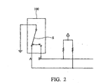
- the operation principle of the mode controller 100 is illustrated in Fig. 2 .
- a first connection terminal A and a second connection terminal B can be triggered to raise its corresponding electric potential.
- the switch S of the controller 100 rotates, a first connection terminal A and a second connection terminal B can be triggered to raise its corresponding electric potential.
- the switch S rotates, a first connection terminal A and a second connection terminal B can be triggered successively by the switch S, and the combination of the electric potentials on the two connection terminals is illustrated in Fig. 3A , in which C represents a sampling point for detection.
- the mode controller 100 rotates counterclockwise, the first connection terminal A and the second connection terminal B are triggered successively by the switch S, and the combination of the electric potentials on the two connection terminals is illustrated in Fig. 3B , in which D represents a sampling point for detection.
- the additional microprocessor basically includes a storage module 210, a detection module 220 and a control module 230.
- the storage module 210 includes a mode list 211 and a pointer (flag) 212, in which the mode list 211 records the available operation modes provided by the computer 300, and the pointer 212 selects one of the available operation modes and designates the selected operation mode as the current operation mode of the computer 300. Note that in order to add a new operation mode, the manufacturer may add the desired operation modes to the mode list 211 without the requirement of additional hardware support.
- the detection module 220 detects the state of the mode controller 100, that is, the detection module 220 detects the combination of the electric potentials on the first connection terminal A and the second connection terminal B, and determines a shift direction of the mode controller 100 according thereto. It should be noted that, in general, two successive sampling points are used for accurate detection, such as sampling points C and E in Fig. 4 , and the detection is valid if the detection results respectively evaluated at the two sampling points match with each other.
- the rotation counterforce applied to the mode controller 100 may likely cause electric potentials on the two connection terminals A and B of the mode controller 1010, as illustrated in Fig. 5 .
- the determination of the shift direction of the mode controller 100 may be wrong if the detection is performed at sampling points F and G. Therefore, the present invention provides two modes to solve the problem.
- the detection module 220 may ignore all triggers of the connection terminals, that is, the detection module 220 stops detecting the combination of the electric potentials within a first predetermined period, such as 200ms, after the first sample point.
- the detection module 220 may ignore the detection result performed at a succeeding sampling point if the shift direction corresponding to the first sampling point is not the same as that of a succeeding sampling point within a second predetermined period after the first sampling point. It should be noted that the two modes could be adopted synthetically or alternatively.
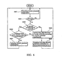
- Fig. 6 shows the processing of the detection module 220 according to the present invention.
- the detection module 220 detects the combination of the electric potentials on the first connection terminal A and the second connection terminal B. If the combination of the electric potentials on the connection terminals A and B does not change and the electric potentials of the two connection terminals both stay low (No in step S602), the flow returns to step S601. If the combination of the electric potentials of the connection terminals A and B changes (Yes in step S602), in step S603, it determines whether the detection has occurred within the second predetermined period after a first detection.
- step S604 the detection module 220 determines a shift direction of the mode controller 100 according thereto, and in step S605, stops detecting the combination of the electric potentials within the first predetermined period. After the first predetermined period expires, the flow returns to step S601.
- step S606 the detection module 220 checks whether the combination of the electric potential is different from the prior one. If not (No in step S606), in step S604, the detection module 220 determines a shift direction of the mode controller according thereto, and performs the process of step S605. If so (Yes in step S606), in step S607, the detection module 220 ignores the combination of the electric potentials of this detection, and the flow returns to step S601.
- the control module 230 selects a second operation mode adjacent to the first operation mode designated by the pointer 212 in the mode list 211 according to the control direction determined by the detection module 220.
- the operation mode following the first operation mode in the mode list 211 is selected if the shift direction of the mode controller 100 is clockwise, and the operation mode preceding the first operation mode in the mode list 211 is selected if the shift direction of the mode controller 100 is counterclockwise.
- the control module 230 also checks the disparity between the first operation mode and the second operation mode to provide a control signal to the computer 300 according to the check result, thereby directing the computer 300 to reboot or execute an application specific to the second operation mode, and subsequently enables the computer to operate in the second operation mode.
- the control module 230 If the first operation mode is a normal operation mode and the second operation mode is one of the sub-modes of the multimedia mode class, the control module 230 generates a control signal to a power circuit (not shown in figures) of the computer 300, thereby directing the computer 300 to reboot and operating in the second operation mode, and executing the application specific to the second operation mode (selected sub-mode of the multimedia mode class). If the first operation mode is one of the sub-modes of the multimedia mode class and the second operation mode is the normal operation mode, the control module 230 generates a control signal to the power circuit of the computer 300, thereby directing the computer 300 to reboot and operate in the normal operation mode.
- the control module 230 If the first operation mode and the second operation mode are different sub-modes of the multimedia mode class respectively, the control module 230 generates a control signal to the computer 300, thereby directing the computer 300 to operate in the second operation mode, and execute the application specific to the second operation mode. It should be noted that the number of applications may be coincident to the number of the sub-modes of the multimedia mode class, and each sub-mode executes a specific application under a purified operating environment.
- a display screen (not shown) can be provided on the computer 300 to show the current operation mode of the computer 300. If the mode controller 100 rotates, the control module 230 may send a signal to display the related information of the second operation mode, such as the name of the operation mode. Further, the operation modes can be selected in order using the mode controller 100. It should be noted that the content shown on the display screen is allowed to change in a preset period, such as 2 seconds, and the additional microprocessor will direct the computer to change operation mode until the mode controller stops.
- Fig. 7 shows the method for operation mode control according to the present invention.
- step S701 the detection module 220 of the additional microprocessor 200 detects the combination of the electric potentials, and in step S702, determines a shift direction of the mode controller 100 according thereto. Then, in step S703, the control module 230 of the additional microprocessor 200 selects a second operation mode adjacent to the first operation mode in the mode list 211 according to the shift direction. Thereafter, in step S704, the control module 230 checks the disparity between the first operation mode and the second operation mode and generates a control signal according to the check result. Afterward, in step S705, the control module 230 transmits the control signal to the computer 300 to direct the computer 300 to reboot or execute a sub-mode application, and subsequently enables the computer 300 to operate in the second operation mode.
- the system and method for controlling the operation of a computer supporting multiple operation modes can easily control the computer supporting multiple operation modes via a mode controller and an additional microprocessor.
- the manufacturer can incorporate the desired operation modes into the mode list without requirement of additional hardware support, thereby saving related costs.
- the computer 300 further provides an application management system to monitor an execution of an application when the computer 300 is operating in a normal operation mode and monitor an execution of the sub-mode applications when the computer 300 is operating in a sub-mode, and thereby prevent the computer 300 from crash due to the abnormality undergone during the execution phase of the applications.
- the application management system is implemented by a watchdog monitor module 121 being embedded in the additional microprocessor 200.
- the watchdog monitor module 121 is a software routine that performs in the background of the operating environment and places the applications running on the computer 100 under surveillance.
- the watchdog monitor module 121 sends a control signal to a power supply circuit (not shown) of the computer 300 via the additional processor 200 to reboot the computer 300 and execute the application 111 using the first processor 112 (which is preferably embodied in the central processing unit of the computer 300) again.
- Fig. 9 shows the processing of the application management system (watchdog monitor module 121) according to a preferred embodiment of the present invention.
- step S901 the first processor 112 of the computer 110 executes the application 111. Then, in step S902, the watchdog monitor module 121 monitors the execution of the application 111 in the computer 300. At this point, if the execution is normal (No in step S903), the process returns to step S902, and the watchdog monitor module 121 continues to monitor the execution of the application 111.
- the watchdog monitor module 121 may alternatively adopt two methodologies to monitor the execution of the application 111. If the first methodology is adopted, the application 111 may be configured to send a LIVE signal to the watchdog monitor module 121 when a first predetermined time interval is reached. If the watchdog monitor module 121 does not receive the LIVE signal from the application 111 within a second predetermined time interval, the watchdog monitor module 121 determines that the execution of the application 111 becomes abnormal. If the second methodology is adopted, the watchdog monitor module 121 may send a CONFIRMATION signal to the application 111 when a first predetermined time interval is reached, and the application 111 may be configured to return a SURVIVING signal to the watchdog monitor module 121 in response to the CONFIRMATION signal. If the watchdog monitor module 121 does not receive the SURVIVING signal from the application 111 in the second predetermined time interval, the watchdog monitor module 121 determines that the execution of the application becomes abnormal.
- step S904 If the execution of the application 111 becomes abnormal (Yes in step S903), in step S904, the watchdog monitor module 121 sends a control signal to the power supply circuit of the computer 300 to reboot the computer 300. Thereafter, in step S905, the first processor 112 of the computer 300 automatically re-executes the application 111 again.
- the execution of the application program on a computer supporting multiple operation modes can be monitored by using an additional microprocessor, which serves in cooperation with a mode controller as an operation mode control mechanism.
Landscapes
- Engineering & Computer Science (AREA)
- Theoretical Computer Science (AREA)
- Quality & Reliability (AREA)
- Physics & Mathematics (AREA)
- General Engineering & Computer Science (AREA)
- General Physics & Mathematics (AREA)
- Debugging And Monitoring (AREA)
- Safety Devices In Control Systems (AREA)
- Hardware Redundancy (AREA)
Claims (11)
- System zum Steuern eines Computers (300), der mehrere Betriebsmodi unterstützt, umfassend:eine Modus-Steuerung (100) zum Erzeugen einer Kombination elektrischer Potenziale an einem ersten Anschluss (A) und einem zweiten Anschluss (B); undeinen zusätzlichen Mikroprozessor (200), der umfasst:ein Speichermodul (210);ein Detektionsmodul (220); undein Steuermodul (230),dadurch gekennzeichnet,dass der Computer (300) eingerichtet ist, um in einem normalen Betriebsmodus oder einem von Untermodi, die einer Multimedia-Modus-Klasse untergeordnet sind, zu arbeiten, und wobei der Computer, wenn er in einem der Untermodi betrieben wird, eingerichtet ist, um eine spezifische Untermodus-Applikation unter einer vereinfachten Version des Betriebssystems auszuführen;dass das Speichermodul eine Modusliste (211), die eine Mehrzahl von Betriebsmodi speichert, und einen Pointer (212), der einen der Betriebsmodi in der Modusliste als einen ersten Betriebsmodus bezeichnet, umfasst;dass das Detektionsmodul eingerichtet ist, um
die Kombination der elektrischen Potenziale an einem ersten Abtastpunkt zu detektieren;
die Kombination der elektrischen Potenziale an einem zweiten Abtastpunkt zu detektieren;
Verschiebungsrichtungen der Modus-Steuerung gemäß den Kombinationen der elektrischen Potenziale zu bestimmen;
die Kombination der elektrischen Potenziale, die an dem zweiten Abtastpunkt detektiert werden, zu ignorieren, falls eine Verschiebungsrichtung, die dem ersten Abtastpunkt entspricht, nicht dieselbe ist wie eine Verschiebungsrichtung, die dem zweiten Abtastpunkt entspricht, und der zweite Abtastpunkt innerhalb einer vorherbestimmten Zeitspanne nach dem ersten Abtastpunkt liegt,dass das Steuermodul eingerichtet ist,
um einen zweiten Betriebsmodus, der zu dem ersten Betriebsmodus in der Modusliste gemäß der Verschiebungsrichtung, die dem zweiten Abtastpunkt entspricht, benachbart ist, auszuwählen,
eine Disparität zwischen dem ersten Betriebsmodus und dem zweiten Betriebsmodus zu überprüfen, und(a) wenn der erste Betriebsmodus einer der Untermodi, die einer Multimedia-Modus-Klasse untergeordnet sind, ist und der zweite Betriebsmodus der normale Betriebsmodus ist, ein Steuersignal für einen Leistungskreis des Computers (300) zu erzeugen, um den Computer anzuweisen, neu zu starten, wodurch dem Computer ermöglicht wird, in dem zweiten Betriebsmodus zu arbeiten, und Ausführen einer Applikation, die für den zweiten Betriebsmodus spezifisch ist; oder(b) wenn der erste Betriebsmodus einer der Untermodi, die einer Multimedia-Modus-Klasse untergeordnet sind, ist und der zweite Betriebsmodus der normale Betriebsmodus ist, ein Steuersignal für den Leistungskreis des Computers zu erzeugen, um den Computer anzuweisen, neu zu starten und in dem normalen Betriebsmodus zu arbeiten; oder(c) wenn der erste Betriebsmodus und der zweite Betriebsmodus unterschiedliche Untermodi sind, die jeweils einer Multimedia-Modus-Klasse untergeordnet sind, ein Steuersignal an den Computer zu erzeugen, um den Computer anzuweisen, in dem zweiten Betriebsmodus zu arbeiten, und Ausführen der Untermodus-Applikation, die für den zweiten Betriebsmodus spezifisch ist. - System nach Anspruch 1, wobei das Steuermodul (230) weiterhin den Pointer (212) aktualisiert, um den zweiten Betriebsmodus gemäß der Verschiebungsrichtung auszuwählen.
- System nach Anspruch 1, wobei das Detektionsmodul (220) weiterhin ein Detektieren der Kombination der elektrischen Potenziale innerhalb einer weiteren vorherbestimmten Zeitspanne nach dem ersten Abtastpunkt stoppt.
- System nach Anspruch 1, welches weiterhin einen Anzeigeschirm umfasst, an den das Steuermodul (230) weiterhin ein Signal sendet, um Information des zweiten Betriebsmodus anzuzeigen.
- System nach Anspruch 1, wobei der zusätzliche Mikroprozessor (200) weiterhin ein Watchdog-Überwachungsmodul (121) umfasst, um eine Ausführung einer Applikation, die von dem Computer ausgeführt wird, zu überwachen.
- System nach Anspruch 5, wobei die Applikation eingerichtet ist, um ein LIVE-Signal an das Watchdog-Überwachungsmodul (121) zu senden, wenn ein erstes vorherbestimmtes Zeitintervall erreicht wird, und wobei das Watchdog-Überwachungsmodul bestimmt, dass die Ausführung der Applikation unnormal wird, falls das LIVE-Signal von der Applikation nicht innerhalb eines zweiten vorherbestimmten Zeitintervalls empfangen wird.
- System nach Anspruch 5, wobei das Watchdog-Überwachungsmodul (121) eingerichtet ist, um ein CONFIRMATION-Signal an die Applikation zu senden, wenn ein erstes vorherbestimmtes Zeitintervall erreicht wird, und wobei die Applikation eingerichtet ist, um ein SURVIVING-Signal an das Überwachungsmodul als Antwort auf das CONFIRMATION-Signal zurückzugeben, wobei das Watchdog-Überwachungsmodul bestimmt, dass die Ausführung der Applikation unnormal wird, falls das SURVIVING-Signal von der Applikation nicht innerhalb eines zweiten vorherbestimmten Zeitintervalls empfangen wird.
- Verfahren zum Steuern eines Computers (300), der mehrere Betriebsmodi unterstützt, umfassend die Schritte:Bereitstellen einer Modus-Steuerung (100), um eine Kombination elektrischer Potenziale an einem ersten Anschluss (A) und einem zweiten Anschluss (B) zu erzeugen; undBereitstellen eines zusätzlichen Mikroprozessors (200),
der ein Speichermodul (210) umfasst,
dadurch gekennzeichnet,dass das Speichermodul eine Modusliste (211), die eine Mehrzahl von Betriebsmodi speichert, und einen Pointer (212), der einen der Betriebsmodi in der Modusliste als einen ersten Betriebsmodus auswählt, umfasst;dass der Computer (300) eingerichtet ist, um in einem normalen Betriebsmodus oder einem der Untermodi, die einer Multimedia-Modus-Klasse untergeordnet sind, zu arbeiten, und wobei der Computer, wenn er in einem der Untermodi betrieben wird, eingerichtet ist, um eine spezifische Untermodus-Applikation unter einer vereinfachten Version des Betriebssystems auszuführen;Detektieren einer Kombination der elektrischen Potenziale an einem ersten Abtastpunkt;Detektieren der Kombination der elektrischen Potenziale an einem zweiten Abtastpunkt;Bestimmen von Verschiebungsrichtungen der Modussteuerung gemäß den Kombinationen der elektrischen Potenziale;Ignorieren der Kombination der elektrischen Potenziale, die an dem zweiten Abtastpunkt detektiert werden, falls eine Verschiebungsrichtung, die dem ersten Abtastpunkt entspricht, nicht dieselbe ist wie eine Verschiebungsrichtung, die dem zweiten Abtastpunkt entspricht, und der zweite Abtastpunkt innerhalb einer vorherbestimmten Zeitspanne nach dem ersten Abtastpunkt liegt,Auswählen eines zweiten Betriebsmodus, der zu dem ersten Betriebsmodus in der Modusliste gemäß der Verschiebungsrichtung, die dem zweiten Abtastpunkt entspricht, benachbart ist;Überprüfen einer Disparität zwischen dem ersten Betriebsmodus und dem zweiten Betriebsmodus; und(a) wenn der erste Betriebsmodus einer der Untermodi, die einer Multimedia-Modus-Klasse untergeordnet sind, ist und der zweite Betriebsmodus der normale Betriebsmodus ist, Erzeugen eines Steuersignals an einen Leistungskreis des Computers (300), um den Computer anzuweisen, neu zu starten, wodurch ermöglicht wird, dass der Computer im zweiten Betriebsmodus arbeitet, und Ausführen einer Applikation, die für den zweiten Betriebsmodus spezifisch ist; oder(b) wenn der erste Betriebsmodus einer der Untermodi, die einer Multimedia-Modus-Klasse untergeordnet sind, ist und der zweite Betriebsmodus der normale Betriebsmodus ist, Erzeugen eines Steuersignals an den Leistungskreis des Computers, um den Computer anzuweisen, neu zu starten und in dem normalen Betriebsmodus zu arbeiten; oder(c) wenn der erste Betriebsmodus und der zweite Betriebsmodus unterschiedliche Untermodi sind, die jeweils einer Multimedia-Modus-Klasse untergeordnet sind, Erzeugen eines Steuersignals an den Computer, um den Computer anzuweisen, in dem zweiten Betriebsmodus zu arbeiten, und Ausführen der Untermodus-Applikation, die für den zweiten Betriebsmodus spezifisch ist. - Verfahren nach Anspruch 8, welches weiterhin umfasst:Aktualisieren des Pointers (212), um den zweiten Betriebsmodus gemäß der Verschiebungsrichtung auszuwählen.
- Verfahren nach Anspruch 8, welches weiterhin umfasst:Stoppen einer Detektion der Kombination der elektrischen Potenziale innerhalb einer ersten vorherbestimmten Zeitspanne nach dem ersten Abtastpunkt.
- Verfahren nach Anspruch 8, welches weiterhin umfasst:Senden eines Signals an einen Anzeigeschirm, um Information des zweiten Betriebsmodus anzuzeigen.
Applications Claiming Priority (4)
| Application Number | Priority Date | Filing Date | Title |
|---|---|---|---|
| CN03147853 | 2003-06-25 | ||
| CN 03147853 CN1567225A (zh) | 2003-06-25 | 2003-06-25 | 应用程序管理系统和方法 |
| CN03148781 | 2003-06-26 | ||
| CNB031487815A CN100468355C (zh) | 2003-06-26 | 2003-06-26 | 操作模式控制系统及方法 |
Publications (3)
| Publication Number | Publication Date |
|---|---|
| EP1492007A2 EP1492007A2 (de) | 2004-12-29 |
| EP1492007A3 EP1492007A3 (de) | 2006-02-08 |
| EP1492007B1 true EP1492007B1 (de) | 2012-10-03 |
Family
ID=33419308
Family Applications (1)
| Application Number | Title | Priority Date | Filing Date |
|---|---|---|---|
| EP20040076739 Expired - Lifetime EP1492007B1 (de) | 2003-06-25 | 2004-06-10 | System und Verfahren zur Steuerung eines Rechners mit verschienen Betriebsmodi |
Country Status (1)
| Country | Link |
|---|---|
| EP (1) | EP1492007B1 (de) |
Family Cites Families (4)
| Publication number | Priority date | Publication date | Assignee | Title |
|---|---|---|---|---|
| US4121284A (en) * | 1972-09-11 | 1978-10-17 | Hyatt Gilbert P | Computerized system for operator interaction |
| US6032207A (en) * | 1996-12-23 | 2000-02-29 | Bull Hn Information Systems Inc. | Search mechanism for a queue system |
| DE19921247C2 (de) * | 1999-05-07 | 2001-08-02 | Siemens Ag | Verfahren und Einrichtung zur Überwachung von Softwareapplikationen |
| JP2002099380A (ja) * | 2000-09-22 | 2002-04-05 | Sony Corp | 携帯型情報処理装置 |
-
2004
- 2004-06-10 EP EP20040076739 patent/EP1492007B1/de not_active Expired - Lifetime
Also Published As
| Publication number | Publication date |
|---|---|
| EP1492007A3 (de) | 2006-02-08 |
| EP1492007A2 (de) | 2004-12-29 |
Similar Documents
| Publication | Publication Date | Title |
|---|---|---|
| USRE43716E1 (en) | Method of fast switching control for different operation systems operated in computer | |
| US10506516B2 (en) | Fleet power management through information storage sharing | |
| CN1282923C (zh) | 可在多种操作模式下运作的计算机系统及其操作方法 | |
| CN114153642A (zh) | 一种系统检测方法及电子设备 | |
| CN107918567A (zh) | 恢复出厂设置的方法、系统、可读存储介质及电子设备 | |
| JP4673193B2 (ja) | 設定優先順序でコンピュータプログラムを実行する方法 | |
| US7383469B2 (en) | Application management system and method | |
| KR20160140415A (ko) | 정보 처리장치, 정보 처리장치의 제어방법, 및 컴퓨터 판독가능한 기억매체 | |
| US8326882B1 (en) | Environment management interface for management of a heterogeneous storage environment | |
| EP1492007B1 (de) | System und Verfahren zur Steuerung eines Rechners mit verschienen Betriebsmodi | |
| US7412467B2 (en) | System and method for operation mode control in a computer system | |
| WO2012145022A1 (en) | Software operability service | |
| WO2003102716A2 (en) | Streaming audio/video guidance in a consumer appliance | |
| JP2004164536A (ja) | 電源状態とシステムモードの分析によりブートモードを制御するシステムと方法 | |
| JP2006072492A (ja) | システム制御装置、システム制御方法およびシステム制御プログラム | |
| EP1114376A1 (de) | Gewaehrleistung des zugriffs zu einem videostapel nach einem anwendungsabsturzs | |
| CN100468355C (zh) | 操作模式控制系统及方法 | |
| CN108509223B (zh) | 一种数据处理方法、装置、系统及存储介质 | |
| CN100424642C (zh) | 以预设优先次序执行电脑程序的方法 | |
| CN1567225A (zh) | 应用程序管理系统和方法 | |
| JPH10111737A (ja) | リセット装置 | |
| KR20100066945A (ko) | 디지털 텔레비전 및 그의 제어방법 | |
| JP6697102B1 (ja) | 情報処理装置、情報処理装置の制御方法、及び、情報処理装置の制御プログラム | |
| JP2578545Y2 (ja) | 電子機器の表示装置 | |
| US10574471B2 (en) | Device control method, information storage medium, control apparatus, and device control system |
Legal Events
| Date | Code | Title | Description |
|---|---|---|---|
| PUAI | Public reference made under article 153(3) epc to a published international application that has entered the european phase |
Free format text: ORIGINAL CODE: 0009012 |
|
| AK | Designated contracting states |
Kind code of ref document: A2 Designated state(s): AT BE BG CH CY CZ DE DK EE ES FI FR GB GR HU IE IT LI LU MC NL PL PT RO SE SI SK TR |
|
| AX | Request for extension of the european patent |
Extension state: AL HR LT LV MK |
|
| PUAL | Search report despatched |
Free format text: ORIGINAL CODE: 0009013 |
|
| AK | Designated contracting states |
Kind code of ref document: A3 Designated state(s): AT BE BG CH CY CZ DE DK EE ES FI FR GB GR HU IE IT LI LU MC NL PL PT RO SE SI SK TR |
|
| AX | Request for extension of the european patent |
Extension state: AL HR LT LV MK |
|
| 17P | Request for examination filed |
Effective date: 20060426 |
|
| AKX | Designation fees paid |
Designated state(s): AT BE BG CH CY CZ DE DK EE ES FI FR GB GR HU IE IT LI LU MC NL PL PT RO SE SI SK TR |
|
| 17Q | First examination report despatched |
Effective date: 20061023 |
|
| REG | Reference to a national code |
Ref country code: DE Ref legal event code: R079 Ref document number: 602004039514 Country of ref document: DE Free format text: PREVIOUS MAIN CLASS: G06F0011000000 Ipc: G06F0003033000 |
|
| RIC1 | Information provided on ipc code assigned before grant |
Ipc: G06F 11/00 20060101ALI20120316BHEP Ipc: G06F 3/033 20060101AFI20120316BHEP |
|
| RTI1 | Title (correction) |
Free format text: SYSTEM AND METHOD OF CONTROLLING A COMPUTER SUPPORTING MULTIPLE OPERATION MODES |
|
| GRAP | Despatch of communication of intention to grant a patent |
Free format text: ORIGINAL CODE: EPIDOSNIGR1 |
|
| GRAS | Grant fee paid |
Free format text: ORIGINAL CODE: EPIDOSNIGR3 |
|
| GRAA | (expected) grant |
Free format text: ORIGINAL CODE: 0009210 |
|
| AK | Designated contracting states |
Kind code of ref document: B1 Designated state(s): AT BE BG CH CY CZ DE DK EE ES FI FR GB GR HU IE IT LI LU MC NL PL PT RO SE SI SK TR |
|
| REG | Reference to a national code |
Ref country code: GB Ref legal event code: FG4D |
|
| REG | Reference to a national code |
Ref country code: CH Ref legal event code: EP Ref country code: AT Ref legal event code: REF Ref document number: 578250 Country of ref document: AT Kind code of ref document: T Effective date: 20121015 |
|
| REG | Reference to a national code |
Ref country code: IE Ref legal event code: FG4D |
|
| REG | Reference to a national code |
Ref country code: NL Ref legal event code: T3 |
|
| REG | Reference to a national code |
Ref country code: DE Ref legal event code: R096 Ref document number: 602004039514 Country of ref document: DE Effective date: 20121129 |
|
| REG | Reference to a national code |
Ref country code: AT Ref legal event code: MK05 Ref document number: 578250 Country of ref document: AT Kind code of ref document: T Effective date: 20121003 |
|
| PG25 | Lapsed in a contracting state [announced via postgrant information from national office to epo] |
Ref country code: SI Free format text: LAPSE BECAUSE OF FAILURE TO SUBMIT A TRANSLATION OF THE DESCRIPTION OR TO PAY THE FEE WITHIN THE PRESCRIBED TIME-LIMIT Effective date: 20121003 |
|
| PG25 | Lapsed in a contracting state [announced via postgrant information from national office to epo] |
Ref country code: SE Free format text: LAPSE BECAUSE OF FAILURE TO SUBMIT A TRANSLATION OF THE DESCRIPTION OR TO PAY THE FEE WITHIN THE PRESCRIBED TIME-LIMIT Effective date: 20121003 Ref country code: FI Free format text: LAPSE BECAUSE OF FAILURE TO SUBMIT A TRANSLATION OF THE DESCRIPTION OR TO PAY THE FEE WITHIN THE PRESCRIBED TIME-LIMIT Effective date: 20121003 Ref country code: ES Free format text: LAPSE BECAUSE OF FAILURE TO SUBMIT A TRANSLATION OF THE DESCRIPTION OR TO PAY THE FEE WITHIN THE PRESCRIBED TIME-LIMIT Effective date: 20130114 |
|
| PG25 | Lapsed in a contracting state [announced via postgrant information from national office to epo] |
Ref country code: BE Free format text: LAPSE BECAUSE OF FAILURE TO SUBMIT A TRANSLATION OF THE DESCRIPTION OR TO PAY THE FEE WITHIN THE PRESCRIBED TIME-LIMIT Effective date: 20121003 Ref country code: CY Free format text: LAPSE BECAUSE OF FAILURE TO SUBMIT A TRANSLATION OF THE DESCRIPTION OR TO PAY THE FEE WITHIN THE PRESCRIBED TIME-LIMIT Effective date: 20121003 Ref country code: GR Free format text: LAPSE BECAUSE OF FAILURE TO SUBMIT A TRANSLATION OF THE DESCRIPTION OR TO PAY THE FEE WITHIN THE PRESCRIBED TIME-LIMIT Effective date: 20130104 Ref country code: PL Free format text: LAPSE BECAUSE OF FAILURE TO SUBMIT A TRANSLATION OF THE DESCRIPTION OR TO PAY THE FEE WITHIN THE PRESCRIBED TIME-LIMIT Effective date: 20121003 Ref country code: PT Free format text: LAPSE BECAUSE OF FAILURE TO SUBMIT A TRANSLATION OF THE DESCRIPTION OR TO PAY THE FEE WITHIN THE PRESCRIBED TIME-LIMIT Effective date: 20130204 |
|
| PG25 | Lapsed in a contracting state [announced via postgrant information from national office to epo] |
Ref country code: AT Free format text: LAPSE BECAUSE OF FAILURE TO SUBMIT A TRANSLATION OF THE DESCRIPTION OR TO PAY THE FEE WITHIN THE PRESCRIBED TIME-LIMIT Effective date: 20121003 |
|
| PG25 | Lapsed in a contracting state [announced via postgrant information from national office to epo] |
Ref country code: BG Free format text: LAPSE BECAUSE OF FAILURE TO SUBMIT A TRANSLATION OF THE DESCRIPTION OR TO PAY THE FEE WITHIN THE PRESCRIBED TIME-LIMIT Effective date: 20130103 Ref country code: CZ Free format text: LAPSE BECAUSE OF FAILURE TO SUBMIT A TRANSLATION OF THE DESCRIPTION OR TO PAY THE FEE WITHIN THE PRESCRIBED TIME-LIMIT Effective date: 20121003 Ref country code: DK Free format text: LAPSE BECAUSE OF FAILURE TO SUBMIT A TRANSLATION OF THE DESCRIPTION OR TO PAY THE FEE WITHIN THE PRESCRIBED TIME-LIMIT Effective date: 20121003 Ref country code: SK Free format text: LAPSE BECAUSE OF FAILURE TO SUBMIT A TRANSLATION OF THE DESCRIPTION OR TO PAY THE FEE WITHIN THE PRESCRIBED TIME-LIMIT Effective date: 20121003 Ref country code: EE Free format text: LAPSE BECAUSE OF FAILURE TO SUBMIT A TRANSLATION OF THE DESCRIPTION OR TO PAY THE FEE WITHIN THE PRESCRIBED TIME-LIMIT Effective date: 20121003 |
|
| PLBE | No opposition filed within time limit |
Free format text: ORIGINAL CODE: 0009261 |
|
| STAA | Information on the status of an ep patent application or granted ep patent |
Free format text: STATUS: NO OPPOSITION FILED WITHIN TIME LIMIT |
|
| PG25 | Lapsed in a contracting state [announced via postgrant information from national office to epo] |
Ref country code: RO Free format text: LAPSE BECAUSE OF FAILURE TO SUBMIT A TRANSLATION OF THE DESCRIPTION OR TO PAY THE FEE WITHIN THE PRESCRIBED TIME-LIMIT Effective date: 20121003 Ref country code: IT Free format text: LAPSE BECAUSE OF FAILURE TO SUBMIT A TRANSLATION OF THE DESCRIPTION OR TO PAY THE FEE WITHIN THE PRESCRIBED TIME-LIMIT Effective date: 20121003 |
|
| 26N | No opposition filed |
Effective date: 20130704 |
|
| REG | Reference to a national code |
Ref country code: DE Ref legal event code: R097 Ref document number: 602004039514 Country of ref document: DE Effective date: 20130704 |
|
| PG25 | Lapsed in a contracting state [announced via postgrant information from national office to epo] |
Ref country code: MC Free format text: LAPSE BECAUSE OF FAILURE TO SUBMIT A TRANSLATION OF THE DESCRIPTION OR TO PAY THE FEE WITHIN THE PRESCRIBED TIME-LIMIT Effective date: 20121003 |
|
| REG | Reference to a national code |
Ref country code: CH Ref legal event code: PL |
|
| REG | Reference to a national code |
Ref country code: IE Ref legal event code: MM4A |
|
| PG25 | Lapsed in a contracting state [announced via postgrant information from national office to epo] |
Ref country code: IE Free format text: LAPSE BECAUSE OF NON-PAYMENT OF DUE FEES Effective date: 20130610 Ref country code: CH Free format text: LAPSE BECAUSE OF NON-PAYMENT OF DUE FEES Effective date: 20130630 Ref country code: LI Free format text: LAPSE BECAUSE OF NON-PAYMENT OF DUE FEES Effective date: 20130630 |
|
| PG25 | Lapsed in a contracting state [announced via postgrant information from national office to epo] |
Ref country code: TR Free format text: LAPSE BECAUSE OF FAILURE TO SUBMIT A TRANSLATION OF THE DESCRIPTION OR TO PAY THE FEE WITHIN THE PRESCRIBED TIME-LIMIT Effective date: 20121003 |
|
| PG25 | Lapsed in a contracting state [announced via postgrant information from national office to epo] |
Ref country code: HU Free format text: LAPSE BECAUSE OF FAILURE TO SUBMIT A TRANSLATION OF THE DESCRIPTION OR TO PAY THE FEE WITHIN THE PRESCRIBED TIME-LIMIT; INVALID AB INITIO Effective date: 20040610 Ref country code: LU Free format text: LAPSE BECAUSE OF NON-PAYMENT OF DUE FEES Effective date: 20130610 |
|
| REG | Reference to a national code |
Ref country code: FR Ref legal event code: PLFP Year of fee payment: 13 |
|
| REG | Reference to a national code |
Ref country code: FR Ref legal event code: PLFP Year of fee payment: 14 |
|
| REG | Reference to a national code |
Ref country code: FR Ref legal event code: PLFP Year of fee payment: 15 |
|
| PGFP | Annual fee paid to national office [announced via postgrant information from national office to epo] |
Ref country code: NL Payment date: 20230515 Year of fee payment: 20 Ref country code: FR Payment date: 20230510 Year of fee payment: 20 Ref country code: DE Payment date: 20230425 Year of fee payment: 20 |
|
| PGFP | Annual fee paid to national office [announced via postgrant information from national office to epo] |
Ref country code: GB Payment date: 20230427 Year of fee payment: 20 |
|
| REG | Reference to a national code |
Ref country code: DE Ref legal event code: R071 Ref document number: 602004039514 Country of ref document: DE |
|
| REG | Reference to a national code |
Ref country code: NL Ref legal event code: MK Effective date: 20240609 |
|
| PG25 | Lapsed in a contracting state [announced via postgrant information from national office to epo] |
Ref country code: GB Free format text: LAPSE BECAUSE OF EXPIRATION OF PROTECTION Effective date: 20240609 |
|
| PG25 | Lapsed in a contracting state [announced via postgrant information from national office to epo] |
Ref country code: GB Free format text: LAPSE BECAUSE OF EXPIRATION OF PROTECTION Effective date: 20240609 |