EP1491321A2 - Process for manufacturing bottles having at least two components, and plant for its implementation - Google Patents
Process for manufacturing bottles having at least two components, and plant for its implementation Download PDFInfo
- Publication number
- EP1491321A2 EP1491321A2 EP04076773A EP04076773A EP1491321A2 EP 1491321 A2 EP1491321 A2 EP 1491321A2 EP 04076773 A EP04076773 A EP 04076773A EP 04076773 A EP04076773 A EP 04076773A EP 1491321 A2 EP1491321 A2 EP 1491321A2
- Authority
- EP
- European Patent Office
- Prior art keywords
- insert
- mould
- tube
- plant
- various polymer
- Prior art date
- Legal status (The legal status is an assumption and is not a legal conclusion. Google has not performed a legal analysis and makes no representation as to the accuracy of the status listed.)
- Withdrawn
Links
- 238000000034 method Methods 0.000 title claims abstract description 16
- 238000004519 manufacturing process Methods 0.000 title claims abstract description 11
- 238000000071 blow moulding Methods 0.000 claims abstract description 3
- 229920001169 thermoplastic Polymers 0.000 claims abstract description 3
- 239000012815 thermoplastic material Substances 0.000 claims abstract description 3
- 239000004416 thermosoftening plastic Substances 0.000 claims abstract description 3
- 229920002994 synthetic fiber Polymers 0.000 claims abstract 2
- 239000000463 material Substances 0.000 claims description 22
- -1 Polyethylene Polymers 0.000 claims description 8
- 238000002347 injection Methods 0.000 claims description 8
- 239000007924 injection Substances 0.000 claims description 8
- 229920000642 polymer Polymers 0.000 claims description 8
- 238000001125 extrusion Methods 0.000 claims description 5
- 239000004698 Polyethylene Substances 0.000 claims description 4
- 239000004743 Polypropylene Substances 0.000 claims description 4
- 229920000573 polyethylene Polymers 0.000 claims description 4
- 229920001155 polypropylene Polymers 0.000 claims description 4
- 239000004800 polyvinyl chloride Substances 0.000 claims description 4
- 229920000915 polyvinyl chloride Polymers 0.000 claims description 4
- 229920001903 high density polyethylene Polymers 0.000 claims description 3
- 239000004700 high-density polyethylene Substances 0.000 claims description 3
- 238000005304 joining Methods 0.000 claims description 3
- 239000002184 metal Substances 0.000 claims description 3
- 229910052751 metal Inorganic materials 0.000 claims description 3
- 239000011521 glass Substances 0.000 claims description 2
- 238000001746 injection moulding Methods 0.000 claims description 2
- 229920003031 santoprene Polymers 0.000 claims description 2
- 229920002725 thermoplastic elastomer Polymers 0.000 claims 1
- 229920005992 thermoplastic resin Polymers 0.000 claims 1
- 238000005034 decoration Methods 0.000 description 6
- 239000004033 plastic Substances 0.000 description 5
- 229920003023 plastic Polymers 0.000 description 5
- 239000000470 constituent Substances 0.000 description 2
- 239000007788 liquid Substances 0.000 description 2
- 230000015572 biosynthetic process Effects 0.000 description 1
- 238000007664 blowing Methods 0.000 description 1
- 239000002537 cosmetic Substances 0.000 description 1
- 239000006071 cream Substances 0.000 description 1
- 239000003599 detergent Substances 0.000 description 1
- 238000009826 distribution Methods 0.000 description 1
- 229920001971 elastomer Polymers 0.000 description 1
- 239000000806 elastomer Substances 0.000 description 1
- 239000003000 extruded plastic Substances 0.000 description 1
- 239000012530 fluid Substances 0.000 description 1
- 150000002739 metals Chemical class 0.000 description 1
- 238000000465 moulding Methods 0.000 description 1
- 239000000825 pharmaceutical preparation Substances 0.000 description 1
- 229940127557 pharmaceutical product Drugs 0.000 description 1
- 229920005989 resin Polymers 0.000 description 1
- 239000011347 resin Substances 0.000 description 1
- 230000000717 retained effect Effects 0.000 description 1
- 230000008961 swelling Effects 0.000 description 1
- 229920003002 synthetic resin Polymers 0.000 description 1
- 239000000057 synthetic resin Substances 0.000 description 1
Images


Classifications
-
- B—PERFORMING OPERATIONS; TRANSPORTING
- B29—WORKING OF PLASTICS; WORKING OF SUBSTANCES IN A PLASTIC STATE IN GENERAL
- B29C—SHAPING OR JOINING OF PLASTICS; SHAPING OF MATERIAL IN A PLASTIC STATE, NOT OTHERWISE PROVIDED FOR; AFTER-TREATMENT OF THE SHAPED PRODUCTS, e.g. REPAIRING
- B29C49/00—Blow-moulding, i.e. blowing a preform or parison to a desired shape within a mould; Apparatus therefor
- B29C49/20—Blow-moulding, i.e. blowing a preform or parison to a desired shape within a mould; Apparatus therefor of articles having inserts or reinforcements ; Handling of inserts or reinforcements
-
- B—PERFORMING OPERATIONS; TRANSPORTING
- B29—WORKING OF PLASTICS; WORKING OF SUBSTANCES IN A PLASTIC STATE IN GENERAL
- B29C—SHAPING OR JOINING OF PLASTICS; SHAPING OF MATERIAL IN A PLASTIC STATE, NOT OTHERWISE PROVIDED FOR; AFTER-TREATMENT OF THE SHAPED PRODUCTS, e.g. REPAIRING
- B29C45/00—Injection moulding, i.e. forcing the required volume of moulding material through a nozzle into a closed mould; Apparatus therefor
- B29C45/17—Component parts, details or accessories; Auxiliary operations
- B29C45/40—Removing or ejecting moulded articles
- B29C45/42—Removing or ejecting moulded articles using means movable from outside the mould between mould parts, e.g. robots
-
- B—PERFORMING OPERATIONS; TRANSPORTING
- B29—WORKING OF PLASTICS; WORKING OF SUBSTANCES IN A PLASTIC STATE IN GENERAL
- B29C—SHAPING OR JOINING OF PLASTICS; SHAPING OF MATERIAL IN A PLASTIC STATE, NOT OTHERWISE PROVIDED FOR; AFTER-TREATMENT OF THE SHAPED PRODUCTS, e.g. REPAIRING
- B29C49/00—Blow-moulding, i.e. blowing a preform or parison to a desired shape within a mould; Apparatus therefor
- B29C49/0005—Blow-moulding, i.e. blowing a preform or parison to a desired shape within a mould; Apparatus therefor characterised by the material
-
- B—PERFORMING OPERATIONS; TRANSPORTING
- B29—WORKING OF PLASTICS; WORKING OF SUBSTANCES IN A PLASTIC STATE IN GENERAL
- B29K—INDEXING SCHEME ASSOCIATED WITH SUBCLASSES B29B, B29C OR B29D, RELATING TO MOULDING MATERIALS OR TO MATERIALS FOR MOULDS, REINFORCEMENTS, FILLERS OR PREFORMED PARTS, e.g. INSERTS
- B29K2021/00—Use of unspecified rubbers as moulding material
-
- B—PERFORMING OPERATIONS; TRANSPORTING
- B29—WORKING OF PLASTICS; WORKING OF SUBSTANCES IN A PLASTIC STATE IN GENERAL
- B29K—INDEXING SCHEME ASSOCIATED WITH SUBCLASSES B29B, B29C OR B29D, RELATING TO MOULDING MATERIALS OR TO MATERIALS FOR MOULDS, REINFORCEMENTS, FILLERS OR PREFORMED PARTS, e.g. INSERTS
- B29K2023/00—Use of polyalkenes or derivatives thereof as moulding material
-
- B—PERFORMING OPERATIONS; TRANSPORTING
- B29—WORKING OF PLASTICS; WORKING OF SUBSTANCES IN A PLASTIC STATE IN GENERAL
- B29K—INDEXING SCHEME ASSOCIATED WITH SUBCLASSES B29B, B29C OR B29D, RELATING TO MOULDING MATERIALS OR TO MATERIALS FOR MOULDS, REINFORCEMENTS, FILLERS OR PREFORMED PARTS, e.g. INSERTS
- B29K2221/00—Use of unspecified rubbers as reinforcement
- B29K2221/003—Thermoplastic elastomers
-
- B—PERFORMING OPERATIONS; TRANSPORTING
- B29—WORKING OF PLASTICS; WORKING OF SUBSTANCES IN A PLASTIC STATE IN GENERAL
- B29K—INDEXING SCHEME ASSOCIATED WITH SUBCLASSES B29B, B29C OR B29D, RELATING TO MOULDING MATERIALS OR TO MATERIALS FOR MOULDS, REINFORCEMENTS, FILLERS OR PREFORMED PARTS, e.g. INSERTS
- B29K2623/00—Use of polyalkenes or derivatives thereof for preformed parts, e.g. for inserts
Definitions
- the present invention relates to the manufacture of plastic bottles for containing miscellaneous products, such as cosmetics, detergent, pharmaceutical and para-pharmaceutical products, and generally all products dispensable in the form of creams, liquids or fluid pastes.
- miscellaneous products such as cosmetics, detergent, pharmaceutical and para-pharmaceutical products
- Such bottles of the state of the art present an outer surface intended to receive labels, or inscriptions and decorations directly printed on the bottle, and are generally manufactured starting from an extruded tube subsequently treated by a blow-moulding process within a suitable mould.
- the need to apply generally flat labels to the bottle or to create inscriptions or decorations directly on the bottle means that at least a portion of the bottle must be cylindrical, or have a curvature suitable for label application or for decoration.
- Said labels and decorations have only a decorative and communicative function, and in no way confer functional characteristics to the product. Moreover, when wetted, the material used for bottle manufacture becomes slippery and difficult to retain with the hands; this makes such bottles very uncomfortable to use if containing for example soapy liquids, and are used in showers or bath tubs.
- the object of the present patent is to provide a process enabling said bottles to be manufactured without any limitation with regard to shape and the associated functional characteristics.
- the process of the invention provides for creating a tube by extruding a synthetic resin chosen from the following:
- HDPE high density polyethylene
- the extrusion is preferably carried out in special machines of the type comprising an extrusion feeder screw with a distribution head for the extruded tube, usually used for manufacturing hollow bodies of thermoplastic materials in one or more layers.
- the extrusion temperature is between 170°C and 220°C.
- an insert is formed of material having particular characteristics different from those of the bottle constituent material.
- Said characteristics can be of tactile type, for example the insert can be soft to the touch and/or anti-slip, or of aesthetic type.
- the insert material is preferably chosen from the following suitable materials:
- Thermoplastic elastomeric resins can also be advantageously used, such as SANTOPRENE, manufactured by Monsanto, or similar materials of miscellaneous production and origin.
- non-plastic materials such as glass and light metals can also be used.
- the insert manufactured separately from the tube in a different plant, is withdrawn from the injection mould and transferred into the blow mould by robotized automatic systems and suitable gripping systems.
- Said automatic systems can also be used to insert inserts of different material into the mould.
- More than one insert can be inserted into the same mould.
- a forming plant will now be described by way of example, comprising an injection device with a single impression for moulding one insert at a time, however in reality a mould with several impressions is used.
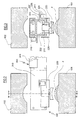
- Figure 1 shows two parts 101 and 102 of an injection mould 100 for forming an insert 3 which on opening the mould remains adhering to its convex part 1a.
- Withdrawal means 200 for the moulded insert are positioned to the side of the injection machine.
- Said means comprise a base portion 201 which slidably supports a beam 210 on which a carriage 220 slides.
- the beam 210 (see Figure 3) is an asymmetric double T beam, the major flanges of which support the slidable carriage 220, which has a shell 221 of C cross-section.
- the shell 221 comprises four idle rollers 222 arranged to slide in four guides 211 provided in the beam flanges.
- a single acting cylinder-piston unit 224 the piston rod of which passes through a hole in the shell and carries a profiled implement 225 for pneumatically receiving and retaining the insert 3.
- an electric gearmotor 226 operating a friction wheel 227 which slides along the beam 210 and drags the carriage into two positions at the ends of the beam 210.
- the base 201 (see Figure 5) comprises a vertical plate 202 carrying four idle rollers 203 which slide in guides 212 provided in the minor flanges of the beam 210.
- the plate 202 carries an electric motor 205 of controlled advancement with, keyed onto its shaft, the friction wheel 206 which slides in contact with the lower flange of the beam 210 to drive the beam 210 with a controlled to-and-fro movement.
- the extent of the movements of the beam 210 is such as to bring its left end, with reference to the figures, into a first position between the parts 101 and 102 of the mould 100, and into a second position external to the mould, to enable it to be closed.
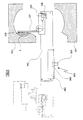
- the transfer means 300 comprise a base portion 301 slidably supporting a beam 310 on which a carriage 320 slides.
- the beam 310 (see Figure 7) is an asymmetric double T beam, the major flanges of which support a slidable carriage 320 having a shell 321 of welded sheet metal.
- the shell 321 comprises four idle rollers 322 which slide in four guides 323 provided in the flanges of the beam 310.
- a pneumatic single acting cylinder-piston unit 342 the piston rod of which is coupled to a rack portion 325, which is parallel to the axis of the cylinder-piston unit and engages an idly mounted gearwheel 326.
- the gearwheel 326 carries a tangential arm 327, on the end of which there is an implement 328 for collecting and pneumatically retaining the insert 3.
- an electric gearmotor 329 operating a friction wheel 330 which slides along the beam 310 and drags the carriage 320 into two positions at the ends of the beam 310.
- the base 301 (see Figure 7) comprises a vertical plate 302 carrying four idle rollers 303 which slide in guides 312 provided in the minor flanges of the beam 310.
- the plate 302 carries an electric motor 305 of controlled advancement with, keyed onto its shaft, the friction wheel 306 which slides in contact with the lower flange of the beam 310 to drive the beam 310 with a controlled to-and-fro movement.
- the extent of the movements of the beam 310 is such as to bring its right end, with reference to the figures, into a first position between the parts 401 and 402 of the blow mould 400, and into a second position external to the mould.
- the line operates in the following manner.
- the beam 210 moves into the position shown in Figure 2, and the carriage 220 moves to the left end, with reference to the figures, of the beam 210.
- the cylinder-piston unit 224 is operated to bring the implement into contact with the insert, which remains adhering thereto by usual suction means, not shown.
- the beam 310 and carriage 320 then move completely towards the right in the figures, to bring this latter into the position shown in Figure 6, where the cylinder-piston unit 324 is operated to rotate the arm 326 until the insert 3 is deposited in the blow mould.
- the inserts can be also deposited on the joining or closure line of the two mould halves.
- a blast of compressed air is fed through suitable nozzles to deform the extruded plastic tube by swelling, so that it is brought to adhere with the walls of the mould, hence incorporating the inserts which have been deposited in the mould, by adhering to their inner sides and filling the voids, and also creating those protuberances and relief decorations which give the bottle particular functional, aesthetic and tactile characteristics.
- said process can start with the withdrawal of the inserts from appropriate containers or stores, and then proceed in the described manner.
Abstract
Description
- The present invention relates to the manufacture of plastic bottles for containing miscellaneous products, such as cosmetics, detergent, pharmaceutical and para-pharmaceutical products, and generally all products dispensable in the form of creams, liquids or fluid pastes.
- Such bottles of the state of the art present an outer surface intended to receive labels, or inscriptions and decorations directly printed on the bottle, and are generally manufactured starting from an extruded tube subsequently treated by a blow-moulding process within a suitable mould. The need to apply generally flat labels to the bottle or to create inscriptions or decorations directly on the bottle means that at least a portion of the bottle must be cylindrical, or have a curvature suitable for label application or for decoration.
- Said labels and decorations have only a decorative and communicative function, and in no way confer functional characteristics to the product. Moreover, when wetted, the material used for bottle manufacture becomes slippery and difficult to retain with the hands; this makes such bottles very uncomfortable to use if containing for example soapy liquids, and are used in showers or bath tubs.
- There is therefore a considerable interest in the manufacture of bottles presenting inserts of different materials compatible with the constituent material of the bottle body, said insert possibly being of anti-slip material and carrying inscriptions or decorations or conferring particular aesthetic, functional or tactile characteristics, and participating in the actual structure of the container by the formation thereon of reliefs, designs, escutcheons and trademarks, sleeves, protuberances, etc. by copenetration of the blow-moulded base material into the outer covering using the force of the compressed air applied during the blowing stage.
- The object of the present patent is to provide a process enabling said bottles to be manufactured without any limitation with regard to shape and the associated functional characteristics.
- Said object is attained according to the invention by the process defined in the claims.
- The characteristics of the invention will be more apparent from the ensuing detailed description of a preferred but non-limiting embodiment of a bottle manufacturing method, given with reference to the accompanying drawing.
- Figure 1 is a schematic plan view of a manufacturing line for the bottle of the invention.
- Figure 2 shows an enlarged part thereof.
- Figure 3 shows the section III-III of Figure 2.
- Figure 4 shows an enlarged portion of Figure 1.
- Figure 5 shows the section V-V of Figure 4.
- Figure 6 shows the end portion of the line of Figure 1.
- Figure 7 shows the section VII-VII of Figure 4.
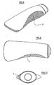
- Figure 8 is a perspective view of the bottle manufactured by the line of Figure 1.
- Figure 9 is a front view of the bottle.
- Figure 10 is a view of the bottle from above.
- Figure 11 is a side view of the bottle.
- Figures 12 and 13 show the insert to be applied to the bottle.
- The process of the invention provides for creating a tube by extruding a synthetic resin chosen from the following:
- Polyethylene, in its various polymer forms;
- Polypropylene, in its various polymer forms;
- PVC (polyvinyl chloride);
- Other plastic materials without any reference to specific commercial names.
- HDPE (high density polyethylene) has proved particularly convenient because of its functional characteristics.
- The extrusion is preferably carried out in special machines of the type comprising an extrusion feeder screw with a distribution head for the extruded tube, usually used for manufacturing hollow bodies of thermoplastic materials in one or more layers.
- The extrusion temperature is between 170°C and 220°C.
- Separately, by means of an injection moulding process, an insert is formed of material having particular characteristics different from those of the bottle constituent material.
- Said characteristics can be of tactile type, for example the insert can be soft to the touch and/or anti-slip, or of aesthetic type.
- The insert material is preferably chosen from the following suitable materials:
- Polyethylene, in its various polymer forms;
- Polypropylene, in its various polymer forms;
- Other plastic materials without any reference to specific commercial names.
- Thermoplastic elastomeric resins can also be advantageously used, such as SANTOPRENE, manufactured by Monsanto, or similar materials of miscellaneous production and origin.
- Alternatively, non-plastic materials such as glass and light metals can also be used.
- If elastomers or plastic materials in general are used, the insert, manufactured separately from the tube in a different plant, is withdrawn from the injection mould and transferred into the blow mould by robotized automatic systems and suitable gripping systems.
- Said automatic systems can also be used to insert inserts of different material into the mould.
- More than one insert can be inserted into the same mould.
- Withdrawal and transfer are carried out, according to the invention, by the robotized manipulation system described hereinafter with reference to the figures.
- A forming plant will now be described by way of example, comprising an injection device with a single impression for moulding one insert at a time, however in reality a mould with several impressions is used.
- Figure 1 shows two
parts injection mould 100 for forming aninsert 3 which on opening the mould remains adhering to its convex part 1a. - Withdrawal means 200 for the moulded insert are positioned to the side of the injection machine.
- Said means comprise a
base portion 201 which slidably supports abeam 210 on which acarriage 220 slides. - The beam 210 (see Figure 3) is an asymmetric double T beam, the major flanges of which support the
slidable carriage 220, which has ashell 221 of C cross-section. Theshell 221 comprises fouridle rollers 222 arranged to slide in fourguides 211 provided in the beam flanges. - To the shell interior there is fixed a single acting cylinder-
piston unit 224, the piston rod of which passes through a hole in the shell and carries a profiledimplement 225 for pneumatically receiving and retaining theinsert 3. - On the outside of the shell there is fixed an
electric gearmotor 226 operating afriction wheel 227 which slides along thebeam 210 and drags the carriage into two positions at the ends of thebeam 210. - The base 201 (see Figure 5) comprises a
vertical plate 202 carrying fouridle rollers 203 which slide inguides 212 provided in the minor flanges of thebeam 210. - The
plate 202 carries anelectric motor 205 of controlled advancement with, keyed onto its shaft, thefriction wheel 206 which slides in contact with the lower flange of thebeam 210 to drive thebeam 210 with a controlled to-and-fro movement. - The extent of the movements of the
beam 210 is such as to bring its left end, with reference to the figures, into a first position between theparts mould 100, and into a second position external to the mould, to enable it to be closed. - To the side of and in continuation of the withdrawal means 200 there are provided
means 300 for transferring theinsert 3 into the interior of the forminghead 400. - The transfer means 300 comprise a
base portion 301 slidably supporting abeam 310 on which acarriage 320 slides. - The beam 310 (see Figure 7) is an asymmetric double T beam, the major flanges of which support a
slidable carriage 320 having ashell 321 of welded sheet metal. Theshell 321 comprises fouridle rollers 322 which slide in fourguides 323 provided in the flanges of thebeam 310. - To the shell interior there is fixed a pneumatic single acting cylinder-piston unit 342, the piston rod of which is coupled to a
rack portion 325, which is parallel to the axis of the cylinder-piston unit and engages an idly mountedgearwheel 326. - The
gearwheel 326 carries atangential arm 327, on the end of which there is animplement 328 for collecting and pneumatically retaining theinsert 3. - On the outside of the shell there is fixed an
electric gearmotor 329 operating afriction wheel 330 which slides along thebeam 310 and drags thecarriage 320 into two positions at the ends of thebeam 310. - The base 301 (see Figure 7) comprises a
vertical plate 302 carrying fouridle rollers 303 which slide inguides 312 provided in the minor flanges of thebeam 310. - The
plate 302 carries anelectric motor 305 of controlled advancement with, keyed onto its shaft, thefriction wheel 306 which slides in contact with the lower flange of thebeam 310 to drive thebeam 310 with a controlled to-and-fro movement. - The extent of the movements of the
beam 310 is such as to bring its right end, with reference to the figures, into a first position between theparts blow mould 400, and into a second position external to the mould. - The line operates in the following manner.
- After the
injection mould 100 has been opened, thebeam 210 moves into the position shown in Figure 2, and thecarriage 220 moves to the left end, with reference to the figures, of thebeam 210. - In this position the
implement 225 is exactly in front of the impression in themould 100 on which theinsert 3 rests and is retained. - The cylinder-
piston unit 224 is operated to bring the implement into contact with the insert, which remains adhering thereto by usual suction means, not shown. - Having collected the insert, the cylinder-piston unit withdraws and the
beam 210 andcarriage 220 assume the position shown in Figure 4. - In this position the implement 225 is exactly in front of the implement 328 carried by the
carriage 320, the cylinder-piston unit 224 then being operated to bring theinsert 3 into contact with the implement 328, which retains it pneumatically by means not shown. - The
beam 310 andcarriage 320 then move completely towards the right in the figures, to bring this latter into the position shown in Figure 6, where the cylinder-piston unit 324 is operated to rotate thearm 326 until theinsert 3 is deposited in the blow mould. - The extruded tube then descends, the blow mould is closed and the bottle is formed, with the insert remaining fixed thereon.
- Depending on the particular arrangement and configuration of the bottle, the inserts can be also deposited on the joining or closure line of the two mould halves.
- After mould closure, a blast of compressed air is fed through suitable nozzles to deform the extruded plastic tube by swelling, so that it is brought to adhere with the walls of the mould, hence incorporating the inserts which have been deposited in the mould, by adhering to their inner sides and filling the voids, and also creating those protuberances and relief decorations which give the bottle particular functional, aesthetic and tactile characteristics.
- If inserts of different material are used, said process can start with the withdrawal of the inserts from appropriate containers or stores, and then proceed in the described manner.
Claims (14)
- A process for manufacturing bottles having at least two components, comprising the following stages:- creating a tube of thermoplastic synthetic material;- creating an insert of elastomeric thermoplastic material;- inserting the tube and insert into a blow mould, and blow-moulding the bottle.
- A process as claimed in claim 1, characterised in that the tube material is chosen from the following: Polyethylene, in its various polymer forms; Polypropylene, in its various polymer forms; PVC (polyvinyl chloride).
- A process as claimed in claim 2, characterised in that the tube material is HDPE.
- A process as claimed in claim 1, characterised in that the insert material is chosen from the following: Polyethylene, in its various polymer forms; Polypropylene, in its various polymer forms; thermoplastic elastomers.
- A process as claimed in claim 1, characterised in that the insert material is an elastomeric thermoplastic resin known as SANTOPRENE.
- A process as claimed in claim 1, characterised in that the insert material is glass.
- A process as claimed in claim 1, characterised in that the insert material is light metal.
- A process as claimed in claim 1, characterised in that the insert is created by injection moulding.
- A process as claimed in claim 1, characterised in that the insert is deposited onto the joining or closure line of the two mould halves.
- A process as claimed in claim 1, characterised in that the injection temperature is between 180 and 210°C in the plastification chamber, and from 15 to 30°C higher in the hot chamber of the mould.
- A plant for manufacturing bottles provided with at least one insert, comprising a tube extrusion line, and means for transferring the insert from the injection mould to the blow head of the extrusion line.
- A plant as claimed in claim 11, characterised in that the inserts are withdrawn from suitable stores.
- A plant as claimed in claim 11, characterised in that the transfer means comprise computer-controlled automatic arms to withdraw the inserts from the edge of the injection machine or from a suitable store or deposit.
- A plant as claimed in claim 11, characterised in that the insert is deposited to straddle the joining line between the two mould halves.
Applications Claiming Priority (2)
| Application Number | Priority Date | Filing Date | Title |
|---|---|---|---|
| ITRE20030060 | 2003-06-24 | ||
| IT000060A ITRE20030060A1 (en) | 2003-06-24 | 2003-06-24 | AT LEAST TWO BOTTLES MANUFACTURING PROCESS |
Publications (2)
| Publication Number | Publication Date |
|---|---|
| EP1491321A2 true EP1491321A2 (en) | 2004-12-29 |
| EP1491321A3 EP1491321A3 (en) | 2005-01-12 |
Family
ID=33398070
Family Applications (1)
| Application Number | Title | Priority Date | Filing Date |
|---|---|---|---|
| EP04076773A Withdrawn EP1491321A3 (en) | 2003-06-24 | 2004-06-16 | Process for manufacturing bottles having at least two components, and plant for its implementation |
Country Status (2)
| Country | Link |
|---|---|
| EP (1) | EP1491321A3 (en) |
| IT (1) | ITRE20030060A1 (en) |
Citations (13)
| Publication number | Priority date | Publication date | Assignee | Title |
|---|---|---|---|---|
| JPS6311317A (en) * | 1986-07-03 | 1988-01-18 | Sekisui Chem Co Ltd | Molding device |
| JPH01141707A (en) * | 1987-11-30 | 1989-06-02 | Pentel Kk | Robot for insert |
| JPH03295629A (en) * | 1990-04-13 | 1991-12-26 | Kyoraku Co Ltd | Blow molding process |
| US5223315A (en) * | 1988-04-06 | 1993-06-29 | Toyo Seikan Kaisha Ltd. | Container equipped with label and production method thereof |
| US5234328A (en) * | 1991-10-29 | 1993-08-10 | Cbw Automation, Inc. | Retrieval system for removing articles formed by a manufacturing apparatus |
| US5266149A (en) * | 1992-01-17 | 1993-11-30 | Continental Pet Technologies, Inc. | In-mold labelling system |
| DE29601739U1 (en) * | 1996-02-01 | 1996-06-20 | Leiritz Otto | Plastic removal system |
| US6054092A (en) * | 1997-07-15 | 2000-04-25 | Asmo Co., Ltd. | Method of manufacturing hollow bodies and method of manufacturing resinous containers |
| US6223397B1 (en) * | 1998-12-17 | 2001-05-01 | Graham Packaging Company, L.P. | Stackable ergonomic handle |
| US20020086085A1 (en) * | 2001-01-04 | 2002-07-04 | Kazutoshi Takayama | Robot for production machine |
| EP1231044A1 (en) * | 2001-02-12 | 2002-08-14 | Owens-Brockway Plastic Products Inc. | Shuttle-type blow molding method and apparatus |
| US20020122906A1 (en) * | 2001-03-01 | 2002-09-05 | Albert Pellicer | Manufacturing process for the blowing technique of a plastic container, specifically a small bottle designed for use in the field of cosmetics |
| US6464922B1 (en) * | 1999-12-10 | 2002-10-15 | Autotec, Inc. | Insertion device for plastic molding |
-
2003
- 2003-06-24 IT IT000060A patent/ITRE20030060A1/en unknown
-
2004
- 2004-06-16 EP EP04076773A patent/EP1491321A3/en not_active Withdrawn
Patent Citations (13)
| Publication number | Priority date | Publication date | Assignee | Title |
|---|---|---|---|---|
| JPS6311317A (en) * | 1986-07-03 | 1988-01-18 | Sekisui Chem Co Ltd | Molding device |
| JPH01141707A (en) * | 1987-11-30 | 1989-06-02 | Pentel Kk | Robot for insert |
| US5223315A (en) * | 1988-04-06 | 1993-06-29 | Toyo Seikan Kaisha Ltd. | Container equipped with label and production method thereof |
| JPH03295629A (en) * | 1990-04-13 | 1991-12-26 | Kyoraku Co Ltd | Blow molding process |
| US5234328A (en) * | 1991-10-29 | 1993-08-10 | Cbw Automation, Inc. | Retrieval system for removing articles formed by a manufacturing apparatus |
| US5266149A (en) * | 1992-01-17 | 1993-11-30 | Continental Pet Technologies, Inc. | In-mold labelling system |
| DE29601739U1 (en) * | 1996-02-01 | 1996-06-20 | Leiritz Otto | Plastic removal system |
| US6054092A (en) * | 1997-07-15 | 2000-04-25 | Asmo Co., Ltd. | Method of manufacturing hollow bodies and method of manufacturing resinous containers |
| US6223397B1 (en) * | 1998-12-17 | 2001-05-01 | Graham Packaging Company, L.P. | Stackable ergonomic handle |
| US6464922B1 (en) * | 1999-12-10 | 2002-10-15 | Autotec, Inc. | Insertion device for plastic molding |
| US20020086085A1 (en) * | 2001-01-04 | 2002-07-04 | Kazutoshi Takayama | Robot for production machine |
| EP1231044A1 (en) * | 2001-02-12 | 2002-08-14 | Owens-Brockway Plastic Products Inc. | Shuttle-type blow molding method and apparatus |
| US20020122906A1 (en) * | 2001-03-01 | 2002-09-05 | Albert Pellicer | Manufacturing process for the blowing technique of a plastic container, specifically a small bottle designed for use in the field of cosmetics |
Non-Patent Citations (3)
| Title |
|---|
| PATENT ABSTRACTS OF JAPAN vol. 0122, no. 08 (M-709), 15 June 1988 (1988-06-15) & JP 63 011317 A (SEKISUI CHEM CO LTD), 18 January 1988 (1988-01-18) * |
| PATENT ABSTRACTS OF JAPAN vol. 0133, no. 98 (M-866), 5 September 1989 (1989-09-05) & JP 1 141707 A (PENTEL KK), 2 June 1989 (1989-06-02) * |
| PATENT ABSTRACTS OF JAPAN vol. 0161, no. 35 (M-1230), 6 April 1992 (1992-04-06) & JP 3 295629 A (KYORAKU CO LTD), 26 December 1991 (1991-12-26) * |
Also Published As
| Publication number | Publication date |
|---|---|
| ITRE20030060A1 (en) | 2004-12-25 |
| EP1491321A3 (en) | 2005-01-12 |
Similar Documents
| Publication | Publication Date | Title |
|---|---|---|
| US4708630A (en) | Apparatus for labeling blow-molded articles by placing label directly on the parison | |
| CZ9700016A3 (en) | Multi-layer preform a process for forming the same and a multi-layer container made from such preform | |
| US4605462A (en) | Method of attaching a sheetlike object, e.g., a label, to a hollow body of plastics | |
| CN1522194A (en) | Method and apparatus for making a plastic container and closure combination | |
| US5503885A (en) | Article with position-defining structure and method and apparatus for making and processing same | |
| JPH07501992A (en) | Method and apparatus for manufacturing plastic cups by injection molding | |
| US3259942A (en) | Method and apparatus for the manufacture of containers | |
| US20070190275A1 (en) | Method for the production of a flexible tube | |
| MXPA02002498A (en) | Releasing undercut moulded containers after a thermoforming process. | |
| JP6595361B2 (en) | Blow molding apparatus and blow molding method | |
| EP2830854B1 (en) | Method and apparatus for making hollow bodies | |
| EP0329888B1 (en) | Applying labels to blow molded articles | |
| JP3138248B2 (en) | Flexible tube and method of manufacturing the same | |
| EP0892711B1 (en) | Process of reshaping decorated plastic materials | |
| EP1491321A2 (en) | Process for manufacturing bottles having at least two components, and plant for its implementation | |
| CN201659689U (en) | Label pasting and bottle taking dual-function mechanical hand | |
| AU645428B2 (en) | Label transfer mechanism for blow molding machinery | |
| JP6533428B2 (en) | Blow molding apparatus and blow molding method | |
| US2954588A (en) | Method of forming hollow plastic articles | |
| US5695792A (en) | Blow molding machine for making hollow plastic articles | |
| CN113365794A (en) | System and method for in-mold labeling | |
| CN111688162A (en) | Bottle surface labeling mechanism for injection blow hollow molding machine | |
| US11685101B2 (en) | Method for manufacturing a thermoplastic container and system for pulling a tube apart | |
| JPH0612912Y2 (en) | Synthetic resin hollow molded product manufacturing equipment | |
| EP0688658A2 (en) | Method and apparatus for producing flat bottles |
Legal Events
| Date | Code | Title | Description |
|---|---|---|---|
| PUAI | Public reference made under article 153(3) epc to a published international application that has entered the european phase |
Free format text: ORIGINAL CODE: 0009012 |
|
| PUAL | Search report despatched |
Free format text: ORIGINAL CODE: 0009013 |
|
| AK | Designated contracting states |
Kind code of ref document: A2 Designated state(s): AT BE BG CH CY CZ DE DK EE ES FI FR GB GR HU IE IT LI LU MC NL PL PT RO SE SI SK TR |
|
| AX | Request for extension of the european patent |
Extension state: AL HR LT LV MK |
|
| AK | Designated contracting states |
Kind code of ref document: A3 Designated state(s): AT BE BG CH CY CZ DE DK EE ES FI FR GB GR HU IE IT LI LU MC NL PL PT RO SE SI SK TR |
|
| AX | Request for extension of the european patent |
Extension state: AL HR LT LV MK |
|
| 17P | Request for examination filed |
Effective date: 20050520 |
|
| AKX | Designation fees paid |
Designated state(s): AT BE BG CH CY CZ DE DK EE ES FI FR GB GR HU IE IT LI LU MC NL PL PT RO SE SI SK TR |
|
| RAP1 | Party data changed (applicant data changed or rights of an application transferred) |
Owner name: PIBIPLAST S.R.L. |
|
| RIN1 | Information on inventor provided before grant (corrected) |
Inventor name: BOSI, GIOVANNI |
|
| GRAP | Despatch of communication of intention to grant a patent |
Free format text: ORIGINAL CODE: EPIDOSNIGR1 |
|
| RIC1 | Information provided on ipc code assigned before grant |
Ipc: B29C 31/04 20060101ALI20090217BHEP Ipc: B29C 45/42 20060101ALI20090217BHEP Ipc: B29C 49/42 20060101ALI20090217BHEP Ipc: B29C 49/20 20060101AFI20090217BHEP |
|
| STAA | Information on the status of an ep patent application or granted ep patent |
Free format text: STATUS: THE APPLICATION IS DEEMED TO BE WITHDRAWN |
|
| 18D | Application deemed to be withdrawn |
Effective date: 20090710 |