EP1490597B1 - Methode und vorrichtung zur hochdruckverdichtung eines gases - Google Patents
Methode und vorrichtung zur hochdruckverdichtung eines gases Download PDFInfo
- Publication number
- EP1490597B1 EP1490597B1 EP03707987A EP03707987A EP1490597B1 EP 1490597 B1 EP1490597 B1 EP 1490597B1 EP 03707987 A EP03707987 A EP 03707987A EP 03707987 A EP03707987 A EP 03707987A EP 1490597 B1 EP1490597 B1 EP 1490597B1
- Authority
- EP
- European Patent Office
- Prior art keywords
- piston
- gas
- compression
- cylinder
- pressure
- Prior art date
- Legal status (The legal status is an assumption and is not a legal conclusion. Google has not performed a legal analysis and makes no representation as to the accuracy of the status listed.)
- Expired - Lifetime
Links
- 238000000034 method Methods 0.000 title claims description 50
- 238000007906 compression Methods 0.000 claims description 221
- 230000006835 compression Effects 0.000 claims description 220
- 239000012530 fluid Substances 0.000 claims description 66
- 239000002826 coolant Substances 0.000 claims description 53
- 238000001816 cooling Methods 0.000 claims description 42
- 238000007667 floating Methods 0.000 claims description 25
- 230000017525 heat dissipation Effects 0.000 claims description 24
- 238000006073 displacement reaction Methods 0.000 claims description 11
- 230000007423 decrease Effects 0.000 claims description 8
- 230000002441 reversible effect Effects 0.000 claims description 5
- 230000004044 response Effects 0.000 claims description 4
- 238000012546 transfer Methods 0.000 claims description 4
- 238000007664 blowing Methods 0.000 claims description 2
- 239000007788 liquid Substances 0.000 claims description 2
- 230000009969 flowable effect Effects 0.000 claims 2
- 238000007599 discharging Methods 0.000 claims 1
- 230000011664 signaling Effects 0.000 claims 1
- 239000007789 gas Substances 0.000 description 122
- 239000000446 fuel Substances 0.000 description 22
- 230000008901 benefit Effects 0.000 description 9
- 238000013461 design Methods 0.000 description 6
- 230000000694 effects Effects 0.000 description 6
- 238000002474 experimental method Methods 0.000 description 6
- VNWKTOKETHGBQD-UHFFFAOYSA-N methane Chemical compound C VNWKTOKETHGBQD-UHFFFAOYSA-N 0.000 description 6
- 239000003570 air Substances 0.000 description 5
- 230000001186 cumulative effect Effects 0.000 description 5
- 230000009286 beneficial effect Effects 0.000 description 3
- 238000002485 combustion reaction Methods 0.000 description 3
- 230000003247 decreasing effect Effects 0.000 description 3
- 230000000977 initiatory effect Effects 0.000 description 3
- 239000003345 natural gas Substances 0.000 description 3
- 238000010248 power generation Methods 0.000 description 3
- 230000000717 retained effect Effects 0.000 description 3
- XLYOFNOQVPJJNP-UHFFFAOYSA-N water Substances O XLYOFNOQVPJJNP-UHFFFAOYSA-N 0.000 description 3
- LYCAIKOWRPUZTN-UHFFFAOYSA-N Ethylene glycol Chemical compound OCCO LYCAIKOWRPUZTN-UHFFFAOYSA-N 0.000 description 2
- 239000012080 ambient air Substances 0.000 description 2
- 230000008859 change Effects 0.000 description 2
- 238000010586 diagram Methods 0.000 description 2
- 238000002347 injection Methods 0.000 description 2
- 239000007924 injection Substances 0.000 description 2
- 238000012423 maintenance Methods 0.000 description 2
- 238000004519 manufacturing process Methods 0.000 description 2
- 238000003860 storage Methods 0.000 description 2
- IJGRMHOSHXDMSA-UHFFFAOYSA-N Atomic nitrogen Chemical compound N#N IJGRMHOSHXDMSA-UHFFFAOYSA-N 0.000 description 1
- 230000004075 alteration Effects 0.000 description 1
- 238000009835 boiling Methods 0.000 description 1
- 230000015556 catabolic process Effects 0.000 description 1
- 238000007796 conventional method Methods 0.000 description 1
- 238000006731 degradation reaction Methods 0.000 description 1
- 238000011161 development Methods 0.000 description 1
- 230000018109 developmental process Effects 0.000 description 1
- 229910001873 dinitrogen Inorganic materials 0.000 description 1
- 238000009826 distribution Methods 0.000 description 1
- 239000002828 fuel tank Substances 0.000 description 1
- WGCNASOHLSPBMP-UHFFFAOYSA-N hydroxyacetaldehyde Natural products OCC=O WGCNASOHLSPBMP-UHFFFAOYSA-N 0.000 description 1
- 238000009434 installation Methods 0.000 description 1
- 239000000463 material Substances 0.000 description 1
- 238000002156 mixing Methods 0.000 description 1
- 238000012986 modification Methods 0.000 description 1
- 230000004048 modification Effects 0.000 description 1
- 230000035515 penetration Effects 0.000 description 1
- 230000002035 prolonged effect Effects 0.000 description 1
- 230000009467 reduction Effects 0.000 description 1
- 238000007789 sealing Methods 0.000 description 1
- 239000000126 substance Substances 0.000 description 1
- 230000001360 synchronised effect Effects 0.000 description 1
- 238000005382 thermal cycling Methods 0.000 description 1
- 230000001052 transient effect Effects 0.000 description 1
Images


Classifications
-
- F—MECHANICAL ENGINEERING; LIGHTING; HEATING; WEAPONS; BLASTING
- F04—POSITIVE - DISPLACEMENT MACHINES FOR LIQUIDS; PUMPS FOR LIQUIDS OR ELASTIC FLUIDS
- F04B—POSITIVE-DISPLACEMENT MACHINES FOR LIQUIDS; PUMPS
- F04B39/00—Component parts, details, or accessories, of pumps or pumping systems specially adapted for elastic fluids, not otherwise provided for in, or of interest apart from, groups F04B25/00 - F04B37/00
- F04B39/06—Cooling; Heating; Prevention of freezing
- F04B39/064—Cooling by a cooling jacket in the pump casing
-
- F—MECHANICAL ENGINEERING; LIGHTING; HEATING; WEAPONS; BLASTING
- F04—POSITIVE - DISPLACEMENT MACHINES FOR LIQUIDS; PUMPS FOR LIQUIDS OR ELASTIC FLUIDS
- F04B—POSITIVE-DISPLACEMENT MACHINES FOR LIQUIDS; PUMPS
- F04B31/00—Free-piston pumps specially adapted for elastic fluids; Systems incorporating such pumps
-
- F—MECHANICAL ENGINEERING; LIGHTING; HEATING; WEAPONS; BLASTING
- F04—POSITIVE - DISPLACEMENT MACHINES FOR LIQUIDS; PUMPS FOR LIQUIDS OR ELASTIC FLUIDS
- F04B—POSITIVE-DISPLACEMENT MACHINES FOR LIQUIDS; PUMPS
- F04B39/00—Component parts, details, or accessories, of pumps or pumping systems specially adapted for elastic fluids, not otherwise provided for in, or of interest apart from, groups F04B25/00 - F04B37/00
- F04B39/06—Cooling; Heating; Prevention of freezing
- F04B39/066—Cooling by ventilation
-
- F—MECHANICAL ENGINEERING; LIGHTING; HEATING; WEAPONS; BLASTING
- F04—POSITIVE - DISPLACEMENT MACHINES FOR LIQUIDS; PUMPS FOR LIQUIDS OR ELASTIC FLUIDS
- F04B—POSITIVE-DISPLACEMENT MACHINES FOR LIQUIDS; PUMPS
- F04B9/00—Piston machines or pumps characterised by the driving or driven means to or from their working members
- F04B9/08—Piston machines or pumps characterised by the driving or driven means to or from their working members the means being fluid
- F04B9/10—Piston machines or pumps characterised by the driving or driven means to or from their working members the means being fluid the fluid being liquid
- F04B9/103—Piston machines or pumps characterised by the driving or driven means to or from their working members the means being fluid the fluid being liquid having only one pumping chamber
- F04B9/107—Piston machines or pumps characterised by the driving or driven means to or from their working members the means being fluid the fluid being liquid having only one pumping chamber rectilinear movement of the pumping member in the working direction being obtained by a single-acting liquid motor, e.g. actuated in the other direction by gravity or a spring
-
- F—MECHANICAL ENGINEERING; LIGHTING; HEATING; WEAPONS; BLASTING
- F04—POSITIVE - DISPLACEMENT MACHINES FOR LIQUIDS; PUMPS FOR LIQUIDS OR ELASTIC FLUIDS
- F04B—POSITIVE-DISPLACEMENT MACHINES FOR LIQUIDS; PUMPS
- F04B9/00—Piston machines or pumps characterised by the driving or driven means to or from their working members
- F04B9/08—Piston machines or pumps characterised by the driving or driven means to or from their working members the means being fluid
- F04B9/10—Piston machines or pumps characterised by the driving or driven means to or from their working members the means being fluid the fluid being liquid
- F04B9/109—Piston machines or pumps characterised by the driving or driven means to or from their working members the means being fluid the fluid being liquid having plural pumping chambers
- F04B9/117—Piston machines or pumps characterised by the driving or driven means to or from their working members the means being fluid the fluid being liquid having plural pumping chambers the pumping members not being mechanically connected to each other
- F04B9/1176—Piston machines or pumps characterised by the driving or driven means to or from their working members the means being fluid the fluid being liquid having plural pumping chambers the pumping members not being mechanically connected to each other the movement of each piston in one direction being obtained by a single-acting piston liquid motor
-
- F—MECHANICAL ENGINEERING; LIGHTING; HEATING; WEAPONS; BLASTING
- F04—POSITIVE - DISPLACEMENT MACHINES FOR LIQUIDS; PUMPS FOR LIQUIDS OR ELASTIC FLUIDS
- F04B—POSITIVE-DISPLACEMENT MACHINES FOR LIQUIDS; PUMPS
- F04B2201/00—Pump parameters
- F04B2201/02—Piston parameters
- F04B2201/0201—Position of the piston
Definitions
- the present invention relates to a method for compressing a gas to a high pressure and to an apparatus for compressing a gas to a high pressure according to the preamble of claim 9.
- a conventional compressor that is operable to increase the pressure of a gas to a high pressure by a ratio of more than four to one typically employs two stages of compression.
- Conventional compressors operate under near isentropic conditions and the use of multiple stages allows heat exchangers, also known as intercoolers, to be employed between stages to cool the gas after each stage.
- United States Patent No. 5,863,186 discloses a method for compressing gases using a multi-stage hydraulically driven compressor.
- the 186 Patent discloses a method and apparatus that does not employ intercoolers, but instead discloses a method of operating multiple cycles of each stage before the target output pressure for that stage is achieved.
- the 186 Patent discloses using a cooling jacket to remove heat from the compressor.
- the compressor still compresses gas under near isentropic conditions but the use of multiple cycles for each stage allows time for cooling the compressed gas, prior to the operation of the next stage. This arrangement does not allow continuous operation of successive stages because this would not allow sufficient time for cooling the gas between stages. Each stage begins after the previous stage is completed.
- two stages are employed to raise the pressure of the gas from about 150 to 500 psi (about 1.0 MPa to 3.4 MPa) to a compressor output target pressure between 3000 to 6000 psi (about 20.7 MPa Mpa to 41.4 MPa).
- Mechanically driven piston compressors typically compensate for their short strokes by operating at high speeds, for example, in hundreds, or more typically, in thousands of cycles per minute.
- Known hydraulically driven reciprocating piston compressor systems that employ piston rods to connect the compressor pistons to a drive means, have also employed low length to diameter ratios (typically less than four to one).
- Low pressure compressors commonly employ a length to diameter ratio of about one to one. As the length to diameter ratio increases, it becomes harder to maintain alignment of the piston rod and piston, which can cause faster wearing around the seals.
- a higher length to diameter ratio also results in increased piston rod weight because of the increased rod length and the need to design against buckling.
- a compressor cylinder with a higher length to diameter ratio also requires a more elongated space to accommodate the compressor.
- such a compressor requires an elongated space to accomodate an elongated cylinder, the piston rod in the extended position, and an elongated hydraulic cylinder. Notwithstanding the problems with alignment and weight, for some applications, such as the aforementioned vehicular fuel compressor application, such an elongated space is not conveniently available.
- Free-floating piston compressors have been developed which use the same cylinder for a hydraulic drive chamber and a compression chamber. Free-floating piston compressors have no piston rod and the piston divides the cylinder into the hydraulic drive chamber and the compression chamber. During a compression stroke, hydraulic fluid is directed to the drive chamber to actuate the piston and compress the fluid in the compression chamber. Conversely, during an intake stroke, hydraulic fluid exits from the drive chamber while fluid enters the compression chamber.
- compressors are unknown that can compress a gas by a ratio of five to one or more, in a single cycle of a single stage, and under significantly less than isentropic conditions. As the compression ratio increases the cumulative temperature rise during the compression cycle also increases, and under near isentropic conditions compression is inefficient.
- compressors With compressors with outlet pressures greater than about 2500 psi (17.2 MPa) and compression ratios greater than about four to one, compressors generally employ at least two stages, and some means for cooling the gas between stages.
- An example of an application that requires a gas to be delivered at a high pressure is a fuel compressor system for an internal combustion engine. It is well known for natural gas fuelled engines to mix the gaseous fuel with intake air at relatively low pressures. However, more recent developments have been made to inject gaseous fuel in diesel cycle engines, wherein the gaseous fuel is injected directly into the combustion chamber late in the compression stroke. Compared to the previously described natural gas fuelled engines, these diesel cycle engines require the gaseous fuel to be compressed to a much higher pressure, for example, to overcome the in-cylinder pressure, to satisfy mass flow requirements, and to improve mixing and penetration.
- a fuel compressor system receives fuel from a source, such as a storage tank or pipeline, and pressurizes the fuel to a pressure in the range of between about 3000 psi and about 3600 psi (between about 20.7 MPa and about 24.8 MPa), for direct injection into an engine combustion chamber.
- a single stage compressor operable to increase gaseous fuel pressure to injection pressure by a ratio of at least about five to one could replace the final two stages of a conventional multi-stage compressor.
- a compressor used for supplying fuel to an engine used as a prime mover for a vehicle or for power generation has different design criteria than a compressor that is used for other applications, such as filling storage vessels.
- a light weight compressor apparatus can reduce vehicle weight and improve overall vehicle efficiency, whereas, reduced weight can not have similar benefits for a compressor installed at a stationary installation. While reliability, durability and efficiency are important for all applications, these characteristics are of particular importance for a compressor used to supply fuel to an engine.
- a compressor failure can result in costly downtime or stranding a vehicle, while inefficient operation increases operating costs.
- WO 00/34655 A1 which forms the starting point of the present invention, discloses a hydraulic compressor arrangement comprising two cylinders with free-floating pistons.
- a hydraulic pump provides a pressurized fluid to operate the pistons so that gas can be compressed by a ratio of up to 15:1 in each stage or cycle, e. g. up to a final gas pressure of 20 MPa.
- Object of the present invention is to provide a method and apparatus for compressing a gas to a high pressure by a ratio of at least 5:1 in a single cycle with improved heat dissipation from a cylinder during a compression stroke.
- the gas is compressed to a high pressure by a ratio of at least about five to one in a single cycle of a single compressor stage with a discharge gas temperature significantly less than isentropic.
- the isentropic temperature is defined as the theoretical temperature of a gas after compression when no heat is dissipated.
- a temperature significantly less than isentropic is defined herein as a gas temperature after compression that is higher than the gas temperature before compression but that is not high enough to inhibit the ability of the compressor to efficiently compress the gas to the desired outlet pressure.
- a discharge temperature that is at least 25 degrees Celsius lower than isentropic, and more preferably at least 50 degrees Celsius lower than isentropic, would be considered a discharge temperature that is significantly less than isentropic.
- a piston stroke length to piston diameter ratio of more than seven to one is employed.
- Using a higher length to diameter ratio provides more surface area for heat dissipation and shorter heat conduction paths within the cylinder chambers to the cylinder walls.
- cylinders with a piston stroke length to piston diameter ratio of between ten to one and one hundred to one are possible.
- What is surprising with the preferred method is the amount of heat that can be dissipated during a compression stroke. Dissipating a significant amount of heat from the compressor cylinder allows gas to be compressed to higher pressures and with higher compression ratios, compared to conventional compressors.
- conventional methods employ a plurality of compression stages with lower compression ratios and means for dissipating heat external to the compressor cylinder, for example, with intercoolers, aftercoolers, and hydraulic fluid coolers.
- a compressor cycle is defined by the completion of an intake stroke and a compression stroke.
- the speed of the compressor measured in cycles per minute also influences the ability of the apparatus to dissipate heat from the compression cylinder.
- the speed of conventional compressors has been generally governed by mass flow requirements (that is the output capacity of the compressor)
- the present method operating the compressor at a speed that enhances heat dissipation.
- the speed does not have a significant effect on heat dissipation.
- piston velocity and/or compressor speed when piston velocity and/or compressor speed (measured in cycles per minute) is reduced by about an order or magnitude, changes in piston velocity and compressor speed begin to have a significant effect on heat dissipation.
- compressor speed is preferably no greater than 20 cycles per minute.
- a compressor speed less than 20 cycles per minute can result in a piston velocity of several feet per second, but as disclosed herein, the higher length to diameter ratio and low number of cycles per minute provide heat dissipation advantages that offset the disadvantages associated with a higher average piston velocity.
- Compressors with lower length to diameter ratios preferably have an average piston velocity less than 1.5 feet per second (about 0.46 meters per second).
- a compressor with a length to diameter ratio of about seven and a half to one preferably has an average piston velocity less than 0.5 feet per second (about 0.15 meter per second).
- Preferred embodiment of the method further comprises transferring heat from the cylinder to the ambient environment through a heat dissipator.
- a heat dissipator is a cooling jacket disposed around the cylinder, wherein the method further comprises directing a coolant to flow through the cooling jacket.
- Heat dissipation is improved by maintaining a coolant flow velocity through the cooling jacket that ensures there are no stagnant pockets within the cooling jacket. Higher velocities can also promote turbulence that enhances heat transfer to the coolant from the cylinder wall.
- the coolant can be conveniently supplied from the coolant reservoir of an engine coolant subsystem.
- the coolant that circulates to an engine is generally too hot to have a substantial effect as a coolant supplied to the compressor cylinder, and so when engine coolant is employed it preferably is supplied from a circuit that is independent from engine cooling circuits.
- the heat dissipator can comprise a plurality of thermally conductive fins protruding from the cylinder. Such a heat dissipator operates by conducting heat from the cylinder to the plurality of fins, which provide a greater surface area for transferring heat to the ambient environment.
- the method can further comprise blowing air through the plurality of fins to enhance heat dissipation.
- the method of dissipating more heat from the compressor cylinder can be combined with controlling piston velocity during the compression stroke.
- the piston preferably travels with at a first velocity during a first portion of the compression stroke and with a second velocity during a second portion of the compression stroke.
- the second portion follows sequentially after the first portion and the second velocity is lower than the first velocity.
- Controlling piston velocity in this manner allows the piston to travel at a higher velocity during the early part of the compression stroke when there is less cumulative temperature rise, and at a slower velocity later in the compression stroke when there is more cumulative temperature rise.
- the timing for changing from the first portion of the compression stroke to the second portion of the compression stroke can be handled in a number of ways. For example, this change can occur when an electronic controller determines that a predetermined criteria is satisfied such as, for example, when gas pressure within the compression chamber or gas discharge temperature exceeds a predetermined set point, or when the piston is at a predetermined location within the cylinder.
- Reducing piston velocity also helps to reduce component wear and methods for improving heat dissipation also reduce the operating temperature of components and seals, which can prolong their life (if such components degrade over time with exposure to heat and/or thermal cycling).
- the method can further comprise controlling piston velocity during a discharge portion of the compression stroke that occurs after the second portion of the compression stroke.
- the gas pressure within the compression chamber is greater than the gas pressure downstream from the compressor cylinder and gas is being discharged from the compression chamber.
- piston velocity is preferably kept substantially constant. Piston velocity during the discharge portion of the piston stroke is preferably equal to or less than piston velocity at the end of the second portion of the compression stroke.
- Piston velocity can be controlled to follow a predetermined speed profile during the compression stroke.
- a speed profile can be selected from a plurality of predetermined speed profiles to control piston velocity at different times during a compression stroke.
- the speed profile controls piston velocity to be highest near the beginning of the compression stroke with piston velocity gradually declining to a lower velocity before stopping at the end of the compression stroke.
- the differences between the plurality of predetermined speed profiles can be piston velocity at different times and/or the rate that piston velocity changes during the compression stroke.
- the speed profile can be selected to maximize thermodynamic efficiency of compression for the desired mass flow rate and compression ratio.
- piston velocity can be controlled to be substantially constant until near the end of the piston stroke when piston velocity can be further reduced until the piston eventually stops at the end of the compression stroke.
- the power supplied to the hydraulic pump can fluctuate during compressor operation, depending upon how piston velocity is controlled.
- An objective of this method is controlling piston velocity to achieve a desired amount of heat dissipation.
- the piston speed profile can be selected in response to a measured operating parameter.
- the selected speed profile can be responsive to desired mass flow rate, inlet gas pressure, desired gas pressure, and desired compression ratio.
- a controller that operates the compressor can select a predetermined speed profile from a plurality of predetermined speed profiles. Of the available speed profiles, the selected speed profile preferably maximizes thermodynamic efficiency of compression for the desired mass flow rate and compression ratio.
- a preferred method further comprises supplying a substantially constant amount of power to a hydraulic pump during a compression stroke. This can be achieved with a constant power hydraulic pump. A consequence of operating in this manner is that piston velocity automatically decreases as gas pressure within the compression chamber increases, which is beneficial for heat dissipation.
- the present disclosure describes an apparatus for compressing a gas to a high pressure.
- the apparatus comprises a reciprocating piston compressor that has a piston stroke length to piston diameter ratio of at least seven to one.
- the apparatus is operable to compress a gas in a single cycle of a single stage from a pressure of between about 300 to about 600 psi (about 2.1 to about 4.1 MPa) to a pressure of between 2500 to 5000 psi (about 17.2 to about 34.5 MPa) with a discharge gas temperature significantly less than isentropic.
- Conventional compressors that are operable to compress a gas to such high pressures typically do not have compression ratios greater than about four to one. Compression ratios higher than five to one are preferred because this allows a gas to be compressed to a high pressure using less stages.
- compression ratios between eight to one and ten to one can be achieved.
- a number of features can be combined with the apparatus to facilitate its operation or to reduce discharge gas temperature further.
- the apparatus can further comprise a controller for maintaing an average piston velocity during a compression stroke that is less than 1.5 feet per second (0.46 meter per second). In some embodiments an average piston velocity of less than 0.5 feet per second (about 0.15 meter per second) is preferred.
- a variable displacement hydraulic pump can be employed for supplying hydraulic fluid to the drive chamber. By changing hydraulic fluid flow rate piston velocity can be changed during a compression stroke.
- the apparatus preferably further comprises a controller for controlling hydraulic pump displacement while operating the apparatus during a compression stroke.
- a controller is operable to control the hydraulic pump displacement to increase, decrease or maintain the flowrate of hydraulic fluid into the drive chamber, whereby piston velocity changes to predetermined speeds at predetermined times during a compression stroke.
- the controller can be an electronic controller or a pre-calibrated mechanical controller.
- an electronic controller can be operable to control the hydraulic pump displacement with response to measured parameters comprising at least one of gas discharge temperature, gas pressure within the compression chamber, and piston position within the compression cylinder.
- variable speed hydraulic pump instead of a variable displacement hydraulic pump, a variable speed hydraulic pump can be employed, whereby piston velocity is controllable to increase or decrease piston velocity during a compression stroke.
- piston velocity can be reduced by reducing the speed of the variable speed hydraulic pump when gas pressure within the compression chamber exceeds a predetermined set point.
- the apparatus can further comprise a constant power hydraulic pump for supplying hydraulic fluid to the drive chamber.
- a feature of the present invention is that it employs length to diameter ratios that are higher than those typically employed by conventional gas compressors. Another advantage of a higher length to diameter ratio is that it can facilitate reducing the proportion of dead space volume to total cylinder volume, which helps to improve compressor efficiency. Preferably the dead space volume is less than 0. 3 % of total compression chamber volume.
- a higher length to diameter ratio also allows longer piston strokes and potentially less cycles per minute for improved efficiency.
- a lower compressor speed can be compensated for by a larger compression chamber volume, provided by an elongated cylinder. At lower compressor speeds, there are additional efficiency gains because there is less switching in the hydraulic system, and with less cycles the dead space at the end of the piston compression stroke is not encountered as often.
- An additional feature that can be combined with the apparatus is a heat dissipator for dissipating heat from the cylinder.
- the heat dissipator substantially surrounds the cylinder for receiving and dissipating heat from the cylinder.
- the heat dissipator comprises a cooling jacket through which a coolant fluid can be directed to receive and remove heat therefrom.
- the cooling jacket preferably comprises a shell structure spaced apart from the cylinder, and a coolant inlet associated with one end of the cylinder and a coolant outlet associated with an opposite end of the cylinder, whereby coolant can enter the cooling jacket through the coolant inlet and flow between the shell and the cylinder to the coolant outlet.
- the heat dissipator comprises a plurality of fins protruding from the cylinder to conduct heat from the cylinder to the ambient environment.
- a fan can be added for directing air to flow between the plurality of fins to further increase heat dissipation.
- the apparatus preferably comprises two cylinders that are operable in tandem to supply a more continuous flow of high-pressure gas.
- the apparatus comprises:
- the first and second reciprocating compressors preferably have substantially the same dimensions.
- the hydraulic drive system can comprise a reversible hydraulic pump for reversing the direction of hydraulic fluid flow.
- the hydraulic drive system comprises a flow-switching valve operable to selectively direct the hydraulic fluid to one of the first and second drive chambers through the hydraulic fluid ports to cause a compression stroke while simultaneously receiving hydraulic fluid from the other one of the first and second drive chambers to cause an intake stroke.
- the apparatus can be combined with one or more of the disclosed features to reduce gas temperature and improve thermodynamic efficiency.
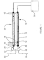
- FIG. 1 is a schematic diagram of a preferred apparatus for compressing gas comprising two hydraulically driven reciprocating compressors 10 and 20.
- Compressors 10 and 20 operate in tandem, with each compressor capable of increasing the pressure of a fluid in a single cycle of each stage by a ratio of at least about five to one.
- a gas can be compressed in such an apparatus from an inlet pressure of 500 or 600 psi (about 3.4 or about 4.1 MPa) to an outlet pressure of at least 2500 to 3000 psi (about 17.2 to about 20.7 MPa).
- Higher compression ratios are preferable because they allow the number of compression stages to be reduced.
- compression ratios of between eight to one and ten to one are possible with embodiments of the disclosed apparatus to achieve outlet pressures of between 2500 psi (about 17.2 Mpa) and 5000 psi (about 34.5 Mpa).
- compressors described herein generally have length to diameter ratios of at least seven to one, but an equally important feature of these embodiments is that they are operable continuously with a discharge gas temperature significantly less than isentropic.
- the compressors schematically shown in FIG. 1 have a length to diameter ratio of about fifteen to one.
- compressor 10 is made to the same specifications as compressor 20, and they are substantially identical.
- the initiation of a compression stroke in one of the compressors is offset from the initiation of a compression stroke in the other compressor by about 180 degrees. That is, the initiation of each piston stroke is roughly synchronized so that when one compressor is beginning its compression stroke, the other compressor is beginning its intake stroke.
- the piston completing an intake stroke typically reaches the end of its stroke shortly before the other piston completes its compression stroke.
- Free-floating piston 12 is movable within compressor cylinder 14 under the influence of a pressure differential on opposite sides of piston 12.
- cylinder 14 On one side of piston 12, cylinder 14 is filled with hydraulic fluid in a drive chamber and on the other side of piston 12, cylinder 14 is filled with gas in a compression chamber.
- Cooling jacket 16 is spaced from cylinder 14, forming an annular cavity through which coolant can flow around cylinder 14 to dissipate heat therefrom.
- Sensor 18 is employed to detect the position of piston 12.
- Inlet pipe 30 is fluidly connected to compressor inlet ports for directing gas into the compressor compression chambers during respective intake strokes.
- One-way flow controllers 32 allow gas to enter the respective compression chambers from inlet pipe 30, and prevent compressed gas from flowing back into inlet pipe 30.
- the term "one-way flow controller" when used herein will be understood by those skilled in the art to be known types of flow controlling devices, generally known as check valves, which permit fluid flow in one direction while preventing flow in the reverse direction, such as, for example, ball check valves, spring assisted ball check valves, wafer check valves, disc check valves, and compressor valves.
- Discharge pipe 36 fluidly connects outlet ports from the compressor compression chamber to a high-pressure system, such as, for example, a fuel supply system for an engine.
- a fuel supply system can include an accumulator vessel that is filled with high-pressure gas to ensure a sufficient supply is available.
- One-way flow controllers 38 allow compressed gas to exit from the compressor chambers and flow to discharge pipe 36, while preventing gas delivered to discharge pipe from returning to the compressor chambers.
- Coolant supply pipe 40 connects the cavity between cooling jacket 16 and cylinder 14 with a supply of coolant. Heat is transferable from cylinder 14 to the coolant and warmed coolant is removed from the cavity through an outlet connected to coolant return pipe 42, which returns the coolant to the cooling system.
- the cooling system employed to supply coolant to the engine can also be employed to supply coolant to the cooling jacket for the compressors.
- a separate cooling loop can be employed if the engine coolant flowing in the engine coolant loop is not significantly cooler than the compressed gas.
- an engine can have a separate cooling loop for turbocharger intercoolers, and the coolant flowing through such a loop can be significantly cooler than the coolant that is used to cool the engine.
- An independent cooling loop is employed if the engine coolant is too hot.
- a higher temperature differential between the coolant and the warmer compressed gas is preferred, and in general, coolant is preferably supplied with a temperature less than 50 degrees Celsius.
- the flow rate of the coolant is high enough to prevent local boiling of the coolant and to prevent stagnant pockets from forming within the cooling jacket cavity. Higher velocity flow also results in less temperature gain in the coolant, more turbulence in the boundary layer next to the cylinder wall, and higher heat transfer rates. Turbulence increases thermal conductivity from the cylinder to the coolant.
- Hydraulic drive systems are well known but a preferred arrangement for the compressor apparatus is a closed loop system.
- a closed loop design helps to synchronize the movements of the pistons in the two compressors and is also more efficient since the hydraulic fluid is delivered to the pump at high pressure from a drive chamber instead of at atmospheric pressure from a reservoir (as in the case of an open loop system).
- Compressor operation is substantially the same for all embodiments.
- hydraulic fluid is directed to the drive chamber while a gas is compressed in the compression chamber.
- free-floating piston 12 advances within cylinder 14 to expand the volume of the drive chamber and reduce the volume of compression chamber.
- the hydraulic pump is a horsepower limited pump so the power required by the pump is substantially constant during operation and the velocity of piston 12 automatically changes during the compression stroke so that it is fastest at the beginning of the compression stroke and progressively slower until discharge pressure is reached.
- a lower piston velocity in the later part of the compression stroke is advantageous for heat dissipation and achieving a discharge gas temperature significantly less than isentropic for efficient compression of the gas.
- relatively little heat is generated in the compression gas while the compression ratio remains below about three to one, so during the early part of the compression stroke the piston velocity can be higher since there is less need to provide time for heat dissipation. Later in the compression stroke, when more heat is generated, a lower piston velocity allows more time for heat dissipation. This method of operation is discussed in greater detail below, with reference to FIG. 5.
- the hydraulic system employs a variable displacement hydraulic pump that can be controlled to change piston velocity for better heat dissipation. This method is also discussed in greater detail below.
- Position sensor 18 is used to determine when piston 12 is near the end of the compression stroke to signal when hydraulic fluid flow should be reversed.
- Position sensor 18 is preferably a sensor that can be mounted on the outside of the compressor body, for ease of maintenance and so that the only ports required in the cylinder head are for fluid entry and exit.
- a magnetic switch can be employed to detect the position of piston 12 near the end of the compression stroke.
- Compressed gas exits cylinder 14 to discharge pipe 36 when the pressure within the compression chamber is greater than the pressure within discharge pipe 36.
- exit pressure of the compressed gas is at least five times greater than the inlet pressure, and in some embodiments exit gas pressure can be between about seven and ten times greater than the inlet pressure.
- One-way flow controllers such as check valves 38, prevent pressurized gas from flowing back into the compression chamber from discharge 36.
- Reciprocating piston compressors normally have a dead space, however, the larger the ratio of dead space to compression chamber volume, the lower the efficiency of the compressor.
- the retained pressurized gas expands and fills the growing volume of the compression chamber.
- the retained gas causes the pressure within the compression cylinder to remain greater than the pressure in inlet pipe 30, preventing new gas from entering.
- a smaller dead space means more new gas can be drawn in from inlet pipe 30 during each intake stroke, resulting in higher compressor efficiency.
- Compressors can be designed to reduce dead space by reducing the amount of cylinder length that corresponds to the dead space. If compressor cylinders of different lengths all have a dead space defined by a cylinder length of between about 1 ⁇ 4 inch and 1/8 inch (about 6 to 3 mm), an advantage of a compressor with a higher length to diameter ratio is that the cylinder length associated with the dead space represents a smaller fraction of compression chamber volumetric capacity.
- piston 12 reverses direction.
- the flow of hydraulic fluid is reversed, for example, by reversing the hydraulic fluid flow through a reversible pump, or by operating a flow switching device that redirects the flow of hydraulic fluid between hydraulic fluid passages so that the drive chamber that was connected to the hydraulic pump discharge during the compression stroke is now connected to the suction of the hydraulic pump (in a closed loop system) or to a drain passage (in an open loop system).
- the pressure of the gas in inlet pipe 30 and the pressure of the gas within the dead space of the compression chamber is greater than the pressure of the hydraulic fluid in the drive chamber.
- piston 12 moves under the influence of the gas pressure within the compression chamber and piston 12 pushes the hydraulic fluid out of the drive chamber and into the suction of the hydraulic pump.
- the compression chamber of cylinder 14 is filled with gas from inlet pipe 30, and this gas is ready for compression in the next compression stroke.
- compressors 10 and 20 operate in tandem with their cycles offset by 180 degrees, so that when compressor 10 is beginning its compression stroke, compressor 20 is beginning its intake stroke, and vice versa. Pairing two compressors in this manner allows a more continuous stream of compressed gas to be supplied to discharge pipe 36, in addition to providing a convenient arrangement for a closed loop hydraulic drive system.
- FIG. 2 shows compressor 100, which illustrates a preferred embodiment of a compressor with a length to diameter ratio of about eight to one.
- Compressor 100 comprises free-floating piston 112 disposed within cylinder 114, defining a compression chamber between piston 112 and end plate 120 and a drive chamber between piston 112 and end plate 122.
- End plate 120 comprises bores 121 for respective inlet and outlet passages from the compression chamber.
- One-way flow controllers can be installed within end plate 120 to control the direction of flow through passages 121.
- End plate 122 comprises bore 123 through which hydraulic fluid flows into and out of the drive chamber.
- Free-floating piston 112 moves within cylinder 114 under the influence of a pressure differential between the drive and compression chambers, as described with reference to FIG. 1.
- Ring seals 113 provide sealing between piston 112 and the interior surface of cylinder 114.
- Free-floating piston 112 preferably reciprocates with an average cycle frequency less than 20 cycles per minute. Higher cycle frequencies allow less time for cooling during compression. As disclosed above, piston velocity preferably changes during the compression stroke to enhance heat dissipation. Compressor cycle frequency for a given flow capacity varies according to the length to diameter ratio and the length of the piston stroke. As will be discussed again with respect to the examples set out below, in the course of a compression stroke a lower average piston velocity also allows more time for heat to be dissipated. However, as the length to diameter ratio increases, the compressor is better able to dissipate heat, and higher piston velocities can be tolerated.
- Cooling jacket 116 is spaced from and surrounds cylinder 114, providing an annular cavity through which a coolant can flow.
- FIG. 3 shows compressor 200, which illustrates a preferred embodiment of a compressor with a length to diameter ratio of about thirty to one.
- a compressor cylinder with a diameter of 1 inch (about 2.54 cm) and a length of about 30 inches (76.2 cm) can be employed to raise the pressure of a gas from an inlet pressure of about 600 psi (about 4.1 MPa) to an outlet pressure of at least about 3000 psi (about 20.7 MPa).
- Compressor 200 comprises free-floating piston 212 disposed within cylinder 214.
- Piston 212 defines a compression chamber between piston 212 and end plate 220 and a drive chamber between piston 212 and end plate 222.
- Free-floating piston 212 moves within cylinder 214 under the influence of a pressure differential between the drive and compression chambers, as described with reference to FIG. 1.
- the heat dissipator in the embodiment of FIG. 3 comprises heat conductive fins 216 that radiate from cylinder 214. Heat is conducted away from cylinder 214 and transferred from fins 216 to the cooler ambient air. For applications that require enhanced cooling, air flow through fins 216 can be increased, for example, by using a fan (not shown) or by positioning cylinder 214 in a location where there is a cool air flow.
- Heat dissipation can be improved by employing smaller cylinder diameters, which result in a shorter heat conduction path between the center of the cylinders and the cylinder walls. Higher length to diameter ratios also yield larger cylinder wall areas which results in a larger surface area for heat transfer. In compressor cylinders with higher length to diameter ratios, these features combine to assist with heat dissipation, making compression with a discharge gas temperature significantly less than isentropic possible.
- a length to diameter ratio equal to or greater than eight to one results in at least twice as much surface area, compared to a cylinder with a piston stoke length to diameter ratio of one to one. Since the amount of surface area continues to increase as the length to diameter ratio increases, for improved heat dissipation, higher length to diameter ratios are preferred over lower length to diameter ratios.
- Reciprocating piston compressors with very high length to diameter ratios can be achieved by employing cylinders with smaller bore diameters.
- length to diameter ratios of between 50:1 and 100:1 can be easily achieved with a bore diameter of 1 ⁇ 2 inch (about 13 mm), and a length of between 25 inches (about 635 mm) for a 50:1 ratio, and 50 inches (about 1270 mm) for a 100:1 ratio.
- Such a small bore diameter results in a relatively small cylinder volume so a plurality of small bore cylinders can be combined to increase flow capacity.
- FIG. 4 is an illustration of a plurality of compressor cylinders 400 that are housed in common cooling jacket 410.
- Common gas distribution manifolds (not shown) can be incorporated into an end plate that also seals an end of cooling jacket 410, or each cylinder can have its own inlet and outlet gas piping.
- An advantage of individual piping for each cylinder is that the operation of each cylinder, or groups of cylinders, can be offset from one another to provide a more steady flow of discharge gas.
- the graphs of FIG. 5 illustrate a methods of controlling compressor operation.
- the power drawn by the hydraulic pump is substantially constant.
- a system that employs a horsepower limited hydraulic pump For example, when a compressor is employed to supply fuel to an engine, the engine typically provides the power needed to drive the hydraulic pump. That is, whether power to the pump is delivered mechanically (for example, via a drive shaft or belts), or indirectly from electrical power generated by the engine, which drives an electric motor, the power used to operate the hydraulic pump is provided by the engine.
- engine stability and efficiency is improved by operating with less power fluctuations, so it is desirable to limit the maximum power of the hydraulic pump so that it operates with substantially constant power requirements.
- FIG. 5 shows the effect of using a horsepower limited hydraulic pump to drive a reciprocating piston compressor.
- the horizontal axis represents time with t1 being the beginning of the compression stroke and t3 being the end of the compression stroke.
- the discharge pressure is reached, and from t2 to t3 gas pressure is substantially constant as gas is discharged from the cylinder. Between t2 and t3 piston velocity is also substantially constant, because constant gas pressure results in constant resistance to piston movement.
- the power drawn by the hydraulic pump is substantially constant except at the very beginning of the compression stroke where power requirements may be lower because of transient conditions.
- a different method of operating the compressor comprises controlling piston velocity to reduce gas discharge temperature to improve heat dissipation and thermodynamics of the compression process, while accepting higher fluctuations in power requirements.
- gas compression occurs during two portions of the compression stroke. During the first portion of the compression stroke the objective is to move the piston quickly since there is less temperature gain at low compression ratios. Accordingly, at the beginning of the compression stroke, piston velocity is relatively high. The temperature of the gas is closer to isentropic because at higher piston velocities there is less time for heat to be dissipated, but this is tolerable because the cumulative temperature rise is relatively low.
- the power drawn by the hydraulic pump is at an intermediate level, because while the hydraulic fluid flow rate is high, the resistance is low since gas pressure is low.
- gas pressure is elevated to discharge pressure.
- the cumulative temperature rise begins to become more significant so piston velocity is reduced to allow more time for heat to dissipate.
- a balance is selected between reducing piston velocity to achieve almost isothermal compression, and increasing compressor speed to achieve a higher gas flow rate, while maintaining discharge gas temperature significantly less than isentropic.
- the power drawn by the hydraulic system increases because when piston velocity is substantially constant, resistance increases as gas pressure increases.
- the gas pressure equals the discharge pressure and gas is discharged from the cylinder as the piston advances.
- the pressure during this part of the compression stroke is substantially constant.
- a smooth discharge flow rate is preferred, so piston velocity is preferably constant.
- Power requirements are also substantially constant at constant pressure and substantially constant piston velocity. The magnitude of the power requirement during the discharge portion of the compression stroke depends upon the predetermined discharge pressure (higher power requirements for higher discharge pressures).
- variable displacement pump such as a swash plate pump with an adjustable swash plate angle can be employed.
- the power requirements for the gas compressor are not constant.
- a variable compressor power requirement is not a problem.
- the speed profile for an individual compressor can be calibrated with regard to gas intake pressure, gas discharge pressure, desired compression ratio, and mass flow requirements.
- the timing for switching between the first portion of the compression stroke and the second portion of the compression stroke can be controlled in a number of ways.
- a flow meter measures the flow of hydraulic fluid to the drive cylinders so that the position of the piston is known from the amount of hydraulic fluid that has been supplied. For example, when the flow meter measures an amount of hydraulic fluid that has a volume that is equal to the volume of the drive chamber at the end of the compression stroke, it is known that the piston is at the end of the compression stroke. Such a flow meter can also be used to determine piston position at intermediate points during the compression stroke allowing piston velocity to be controlled based upon piston position.
- piston velocity can begin a compression stroke at a predetermined velocity
- a pressure sensor and/or temperature sensor can be employed to determine when piston velocity should be decreased to allow more time for heat dissipation.
- piston velocity can be controlled to follow many speed profiles.
- the graph shown in FIG. 6 represents data collected from a gas compressor that employed a free floating hydraulically driven piston.
- the compressor cylinder had a stroke length of 10-1/4 inches (about 261 mm) and a bore diameter of 1-3/8 inches (about 34.9 mm), which corresponds to a length to diameter ratio of about 7.5:1.
- the cylinder was cooled by ambient air that had a temperature of about 10 degrees Celsius.
- the graph of FIG. 6 plots temperature rise in degrees Celsius on the vertical axis against compressor speed in cycles per minute. Nitrogen gas was supplied to the compressor at a temperature of about 0 degrees Celsius.
- a compressor speed of 20 cycles per minute correlates to an average piston velocity of 0.57 feet per second, and as shown by the graph of FIG. 6, piston velocity is preferably still lower.
- piston velocity is preferably still lower.
- a compressor speed of about 5 cycles per minute correlates to an average piston velocity of 0.14 feet per second.
- Conventional hydraulically driven piston compressors employ piston velocities that are orders of magnitude higher. At conventional piston velocities the benefits of reduced temperature rise in the compression fluid is not realized, and there is no indication that such benefits can be significant until compressor speed is reduced well below conventional levels.
- the data set out in table 3 below was collected from three experiments done with a larger gas compressor that employed a free floating hydraulically driven piston to compress natural gas.
- the compressor cylinder had a stroke length of 54 inches (about 1370 mm) and a bore diameter of 2-1/2 inches (about 64 mm), which corresponds to a length to diameter ratio of about 21.6:1.
- a coolant consisting of 50 % glycol and 50 % water was circulated through a cooling jacket surrounding the compressor cylinder.
- the temperature of the coolant supplied to the water jacket was about 15 degrees Celsius.
- the hydraulic system employed a constant power hydraulic pump, resulting in piston velocity automatically decreasing as resistance to piston movement increased with increasing gas pressure.
- reducing temperature rise has been disclosed as being advantageous for thermodynamic and energy efficiency, it is also important to note that reducing temperature rise also results in a cooler apparatus, which is in itself beneficial.
- the apparatus comprises moving parts that require dynamic seals.
- the effective life of dynamic seals is typically prolonged by maintaining them at cooler temperatures during operation.
Landscapes
- Engineering & Computer Science (AREA)
- Mechanical Engineering (AREA)
- General Engineering & Computer Science (AREA)
- Compressor (AREA)
- Compressors, Vaccum Pumps And Other Relevant Systems (AREA)
Claims (27)
- Verfahren zum Verdichten eines Gases in einem hydraulisch angetriebenen Verdichter mit hin- und hergehendem Kolben (10, 20, 100, 200), umfassend einen Zylinder (14, 114, 214, 400); einen freifliegenden bzw. schwimmenden Kolben (12, 112, 212), welcher im Zylinder (14, 114, 214, 400) zwischen einem ersten geschlossenen Ende und einem zweiten geschlossenen Ende angeordnet ist; eine Verdichtungskammer, welche durch ein Volumen im Zylinder (14, 114, 214, 400) zwischen dem ersten geschlossenen Ende und dem Kolben (12, 112, 212) definiert ist; und eine Antriebskammer, welche durch ein Volumen im Zylinder (14, 114, 214, 400) zwischen dem zweiten geschlossenen Ende und dem Kolben (12, 112, 212) definiert ist;
wobei das Verfahren umfasst:(a) in einem Ansaughub,
Zuführen des Gases zur Verdichtungskammer;
Entfernen des Hydraulikfluids aus der Antriebskammer;
wobei das Gas, welches der Verdichtungskammer zugeführt wird, einen höheren Druck als das Hydraulikfluid in der Antriebskammer aufweist, was den Kolben (12, 112, 212) veranlasst, sich zu bewegen, um das Volumen der Antriebskammer zu verringern und das Volumen der Verdichtungskammer zu vergrößern, bis die Verdichtungskammer sich auf ein angestrebtes Volumen ausgedehnt hat und mit Gas gefüllt ist; und(b) in einem Verdichtungshub,
Zuführen des Hydraulikfluids zur Antriebskammer, wobei das Hydraulikfluid in der Antriebskammer einen höheren Druck als das Gas in der Verdichtungskammer aufweist, was den Kolben (12, 112, 212) veranlasst, sich zu bewegen, um das Volumen der Antriebskammer zu vergrößern und das Volumen der Verdichtungskammer zu verringern, wodurch der Druck des Gases, welches in der Verdichtungskammer gehalten wird, erhöht wird;
Ausstoßen des Gases aus der Verdichtungskammer, wenn der Druck des Gases in einem einzelnen Zyklus auf einen Druck von wenigstens 2500 psi (17,2 MPa) erhöht ist, was wenigstens fünfmal größer als der Druck des Gases ist, das der Verdichtungskammer zugeführt wird;
Einsetzen eines Kolbenhublänge-zu-Kolbendurchmesser-Verhältnisses von mehr als sieben zu eins; und
Ableiten von Wärme vom Zylinder (14, 114, 214, 400) während des Verdichtungshubes, wobei das Gas aus der Verdichtungskammer mit einer Temperatur deutlich geringer als isentropisch ausgestoßen wird. - Verfahren gemäß Anspruch 1, dadurch gekennzeichnet, dass das Verfahren des Weiteren das Einsetzen eines Zylinders (14, 114, 214, 400) mit einem Kolbenhublänge-zu-Kolbendurchmesser-Verhältnis von zwischen zehn zu eins bis einhundert zu eins umfasst und/oder das Verfahren des Weiteren eine durchschnittliche Kolbengeschwindigkeit aufrecht erhält, welche niedriger als oder gleich 0,46 Meter pro Sekunde (1,5 Fuß pro Sekunde) ist und/oder das Verfahren des Weiteren das Übertragen von Wärme vom Zylinder (14, 114, 214, 400) auf die Umgebung durch einen Wärmeabstrahler umfasst.
- Verfahren gemäß Anspruch 2, dadurch gekennzeichnet, dass der Wärmeabstrahler einen Kühlmantel (16, 116, 410) umfasst, welcher rund um den Zylinder (14, 114, 214, 400) angeordnet ist, und ein Kühlmittel so leitet, um durch den Kühlmantel (16, 116, 410) zu fließen, wobei vorzugsweise das Kühlmittel durch den Kühlmantel (16, 116, 410) mit einer Geschwindigkeit fließt, die sicherstellt, dass sich keine strömungsfreien Taschen im Kühlmantel (16, 116, 410) bilden, und/oder wobei das Verfahren des Weiteren das Zuführen des Gases zu einem Motor und das Zuführen des Kühlmittels von einem Motorkühlmittelbehälter, aber von einem Kreislauf, der von Motorkühlmittelkreisläufen unabhängig ist, umfasst.
- Verfahren gemäß Anspruch 3, dadurch gekennzeichnet, dass der Wärmeabstrahler eine Mehrzahl von Rippen (216) umfasst, welche vom Zylinder vorragen, und dass der Wärmeabstrahler durch Leiten von Wärme vom Zylinder (14, 114, 214, 400) auf die Mehrzahl der Rippen (216) arbeitet, welche eine größere Oberfläche zum Übertragen der Wärme auf eine Umgebung bereitstellen, wobei vorzugsweise das Verfahren des Weiteren das Durchblasen von Luft durch die Mehrzahl von Rippen (216) umfasst, um die Wärmeableitung zu verstärken.
- Verfahren gemäß einem der vorangehenden Ansprüche, dadurch gekennzeichnet, dass das Verfahren des Weiteren das Steuern, wann der Kolben (12, 112, 212) seine Richtung umkehrt, indem erfühlt wird, wann der Kolben (12, 112, 212) nahe einem Ende des Zylinders (14, 114, 214, 400) ist, und/oder das Steuern der Kolbengeschwindigkeit während des Verdichtungshubes umfasst, wobei der Kolben mit einer ersten Geschwindigkeit während eines ersten Abschnitts des Verdichtungshubes und mit einer zweiten Geschwindigkeit während eines zweiten Abschnitts des Verdichtungshubes verfährt, wobei der zweite Abschnitt im Anschluss auf den ersten Abschnitt folgt und die zweite Geschwindigkeit niedriger als die erste Geschwindigkeit ist.
- Verfahren gemäß Anspruch 5, dadurch gekennzeichnet, dass das Verfahren des Weiteren das Wechseln vom ersten Abschnitt des Verdichtungshubes in den zweiten Abschnitt des Verdichtungshubes umfasst, wenn der Gasdruck in der Verdichtungskammer einen vorbestimmten Sollwert übersteigt, und/oder dass das Verfahren des Weiteren das Steuern der Kolbengeschwindigkeit während eines Ausstoßabschnitts des Verdichtungshubes umfasst, welcher nach dem zweiten Abschnitt des Verdichtungshubes auftritt, wenn Gas von der Verdichtungskammer ausgestoßen wird, wobei die Kolbengeschwindigkeit während des Ausstoßabschnitts im Wesentlichen konstant gehalten wird, wobei vorzugsweise die Kolbengeschwindigkeit während des Ausstoßabschnitts des Verdichtungshubes gleich oder niedriger als die Kolbengeschwindigkeit während des zweiten Abschnitts des Verdichtungshubes ist.
- Verfahren gemäß einem der vorangehenden Ansprüche, dadurch gekennzeichnet, dass das Verfahren des Weiteren das Steuern der Kolbengeschwindigkeit umfasst, um einem vorbestimmten Drehzahlprofil zu folgen, wobei vorzugsweise das Verfahren des Weiteren das Auswählen des vorbestimmten Drehzahlprofils als Reaktion auf einen gemessenen Betriebsparameter umfasst, der vorzugsweise mindestens einen Parameter aus der Gruppe angestrebte Massendurchsatzrate, Einlassgasdruck, angestrebter Ausstoßgasdruck und angestrebtes Verdichtungsverhältnis umfasst, und/oder wobei das Verfahren vorzugsweise des Weiteren das Auswählen des vorbestimmten Drehzahlprofils aus einer Mehrzahl von vorbestimmten Drehzahlprofilen umfasst, um die Kolbengeschwindigkeit zu unterschiedlichen Zeitpunkten während eines Verdichtungshubes zu steuern, wobei die Drehzahlprofile die Kolbengeschwindigkeit nahe dem Beginn des Verdichtungshubes am höchsten sein lassen, wobei die Kolbengeschwindigkeit allmählich auf eine niedrigere Geschwindigkeit vor dem Anhalten am Ende des Verdichtungshubes abnimmt, wobei der Unterschied zwischen der Mehrzahl von vorbestimmten Drehzahlprofilen die Kolbengeschwindigkeit zu verschiedenen Zeitpunkten und/oder die Rate der Kolbengeschwindigkeitsveränderungen während des Verdichtungshubes sein kann, wobei aus der Mehrzahl der vorbestimmten Drehzahlprofile das ausgewählte, vorbestimmte Drehzahlprofil den thermodynamischen Wirkungsgrad der Verdichtung für die angestrebte Massendurchsatzrate und das Verdichtungsverhältnis maximiert.
- Verfahren gemäß einem der vorangehenden Ansprüche, dadurch gekennzeichnet, dass das Verfahren des Weiteren das allmähliche Verringern der Kolbengeschwindigkeit während eines Verdichtungshubes, bis das Gas aus der Verdichtungskammer ausgestoßen wird, und dann das Beibehalten einer im Wesentlichen konstanten Kolbengeschwindigkeit für den verbleibenden Rest des Verdichtungshubes und/oder das Zuführen einer im Wesentlichen konstanten elektrischen Leistung an die Hydraulikpumpe während eines Verdichtungshubes umfasst, wobei die Kolbengeschwindigkeit abnimmt, während der Gasdruck innerhalb der Verdichtungskammer ansteigt.
- Vorrichtung zum Verdichten eines Gases auf einen hohen Druck, wobei die Vorrichtung umfasst:(a) einen hohlen Zylinder (14, 114, 214, 400); und(b) einen freifliegenden bzw. schwimmenden Kolben (12, 112, 212), welcher sich im Zylinder (14, 114, 214, 400) hin und her bewegen lässt; wobei der Kolben (12, 112, 212) den Zylinder (14, 114, 214, 400) in:wobei der Kolben (12, 112, 212) so betrieben ist, um ein Gas um ein Verhältnis von wenigstens fünf zu eins in einem einzelnen Zyklus auf einen Auslassdruck von wenigstens 2500 psi (17,2 MPa) zu verdichten;eine Verdichtungskammer, in welche das Gas eingeleitet, verdichtet und ausgestoßen werden kann; undeine Antriebskammer teilt, in welche ein Hydraulikfluid zum Betätigen des Kolbens (12, 112, 212) eingeleitet und entfernt werden kann;
dadurch gekennzeichnet,
dass das Verhältnis von Kolbenhublänge zu Kolbendurchmesser wenigstens sieben zu eins beträgt und dass das verdichtete Gas eine Ausstoßgastemperatur von wenigstens 25 Grad Celsius niedriger als isentropisch aufweist. - Vorrichtung gemäß Anspruch 9, dadurch gekennzeichnet, dass die Vorrichtung des Weiteren einen Regler zum Beibehalten einer durchschnittlichen Kolbengeschwindigkeit während eines Verdichtungshubes, die weniger als 0,46 Meter pro Sekunde (1,5 Fuß pro Sekunde) beträgt, umfasst und/oder dass das Verhältnis zwischen Kolbenhublänge und Kolbendurchmesser zwischen zehn zu eins und einhundert zu eins liegt.
- Vorrichtung gemäß Anspruch 9 oder 10, dadurch gekennzeichnet, dass die Vorrichtung des Weiteren eine Hydraulikpumpe mit veränderlichem Hubraum zum Zuführen von Hydraulikfluid zur Antriebskammer umfasst, wobei die Kolbengeschwindigkeit während eines Verdichtungshubes veränderbar ist, wobei vorzugsweise die Vorrichtung des Weiteren einen Regler zum Regeln des Hydraulikpumpenhubraums während des Betreibens der Vorrichtung während eines Verdichtungshubes umfasst.
- Vorrichtung gemäß Anspruch 11, dadurch gekennzeichnet, dass der Regler betreibbar ist, um den Hydraulikpumpenhubraum zu steuern, um die Durchsatzrate an Hydraulikfluid in die Antriebskammer zu erhöhen, abzusenken oder beizubehalten, wobei sich die Kolbengeschwindigkeit auf vorbestimmte Geschwindigkeiten zu vorbestimmten Zeitpunkten während eines Verdichtungshubs verändert, und/oder der Regler betreibbar ist, um den Hydraulikpumpenhubraum als Reaktion auf gemessene Parameter zu steuern, die wenigstens einen Parameter aus der Gruppe Gasausstoßtemperatur, Gasdruck im Verdichtungszylinder und Kolbenposition im Verdichtungszylinder umfassen.
- Vorrichtung gemäß einem der Ansprüche 9 bis 12, dadurch gekennzeichnet, dass die Vorrichtung des Weiteren eine Hydraulikpumpe mit konstanter Leistung zum Zuführen von Hydraulikfluid zur Antriebskammer umfasst und/oder dass das Toter-Raum-Volumen weniger als 0,3% des gesamten Verdichtungskammervolumens beträgt.
- Vorrichtung gemäß einem der Ansprüche 9 bis 13, dadurch gekennzeichnet, dass die Vorrichtung des Weiteren einen Wärmeabstrahler zum Ableiten von Wärme vom Zylinder umfasst, wobei der Wärmeabstrahler vorzugsweise im Wesentlichen den Zylinder (14, 114, 214, 400) zum Aufnehmen und Ableiten von Wärme vom Zylinder (14, 114, 214, 400) umgibt.
- Vorrichtung gemäß Anspruch 14, dadurch gekennzeichnet, dass der Wärmeabstrahler einen Kühlmantel (16, 116, 410) umfasst, durch welchen ein Kühlmittelfluid geleitet werden kann, um Wärme davon aufzunehmen und zu entfernen, wobei vorzugsweise der Kühlmantel (16, 116, 410) einen Schalenaufbau, der vom Zylinder (14, 114, 214, 400) beabstandet ist, und einen Kühlmitteleinlass, der einem Ende des Zylinders (14, 114, 214, 400) zugeordnet ist, und einen Kühlmittelauslass umfasst, der einem gegenüberliegenden Ende des Zylinders (14, 114, 214, 400) zugeordnet ist, wobei das Kühlmittel in den Kühlmantel (16, 116, 410) durch den Kühlmitteleinlass einströmen und zwischen der Schale und dem Zylinder (14, 114, 214, 400) zum Kühlmittelauslass fließen kann.
- Vorrichtung gemäß Anspruch 14 oder 15, dadurch gekennzeichnet, dass der Wärmeabstrahler eine Mehrzahl von Rippen (216) umfasst, welche vom Zylinder (14, 114, 214,400) vorragen, um Wärme vom Zylinder (14, 114, 214, 400) an die Umgebung wegzuleiten, wobei vorzugsweise der Wärmeabstrahler des Weiteren ein Gebläse zum Lenken von Luft umfasst, um zwischen der Mehrzahl von Rippen (216) durchzufließen.
- Vorrichtung gemäß einem der Ansprüche 9 bis 16, dadurch gekennzeichnet, dass die Vorrichtung zwei Zylinder (14, 114, 214, 400) umfasst, die im Tandembetrieb arbeiten, um einen stetigeren Strom an Hochdruckgas zuzuführen, und/oder einen Gaseinlasskanal, durch welchen das Gas in die Verdichtungskammer fließen kann, und einen getrennten Gasauslasskanal umfasst, durch welchen das Gas aus der Verdichtungskammer ausgestoßen werden kann.
- Vorrichtung gemäß Anspruch 17, dadurch gekennzeichnet, dass die Vorrichtung des Weiteren einen Einweg-Durchflussregler zum Steuern des Einwegdurchflusses des Gases in die Verdichtungskammer durch den Gaseinlasskanal und einen Einweg-Durchflussregler zum Steuern des Einwegdurchflusses des Gases aus der Verdichtungskammer durch den Gasauslasskanal umfasst, wobei vorzugsweise die Gaseinlass- und Gasauslasskanäle durch eine Endplatte (120, 220) hindurchgehen, welche die Verdichtungskammer abdichtet, und die Einweg-Durchflussregler jeweils in der Endplatte (120, 220) angeordnet sind.
- Vorrichtung gemäß einem der Ansprüche 9 bis 18, dadurch gekennzeichnet, dass die Vorrichtung des Weiteren einen Sensor (18) zum Erfassen umfasst, wann der Kolben (12, 112, 212) einen Verdichtungshub abgeschlossen hat, und/oder dass die Vorrichtung mit einem Verdichtungsverhältnis von zwischen acht zu eins und zehn zu eins betreibbar ist.
- Vorrichtung gemäß einem der Ansprüche 9 bis 19, dadurch gekennzeichnet, dass die Vorrichtung umfasst:(a) einen ersten Kolbenverdichter (10), welcher einen ersten hohlen zylindrischen Körper mit fluiddichten Enden, einen ersten freifliegenden bzw. schwimmenden Kolben (12, 112, 212) umfasst, welcher im ersten hohlen zylindrischen Körper angeordnet ist, wobei er eine erste Antriebskammer mit einer Hydraulikfluidöffnung (123) und eine erste Verdichtungskammer mit einer Gasöffnung (121) definiert, welche selektiv mit einem Niederdruckgaszufuhrsystem oder einem Hochdruckgassystem verbindbar ist;(b) einen zweiten Kolbenverdichter (20), welcher einen zweiten hohlen zylindrischen Körper mit fluiddichten Enden, einen zweiten freifliegenden bwz. schwimmenden Kolben (12, 112, 212) umfasst, welcher im zweiten hohlen zylindrischen Körper angeordnet ist, wobei er eine zweite Antriebskammer mit einer Hydraulikfluidöffnung (123) und eine zweite Verdichtungskammer mit einer Gasöffnung (121) definiert, welche selektiv mit dem Niederdruckgaszufuhrsystem oder dem Hochdruckgassystem verbindbar ist;(c) ein hydraulisches Antriebssystem, welches betreibbar ist, um abzuwechseln zwischen:wobei für jeden der hohlen zylindrischen Körper das Verhältnis zwischen Kolbenhublänge und freifliegendem Kolbendurchmesser wenigstens sieben zu eins ist,Zuführen von Hydraulikfluid zur ersten Antriebskammer bei gleichzeitigem Zurücksaugen von Hydraulikfluid aus der zweiten Antriebskammer, undEntfernen des Hydraulikfluids aus der ersten Antriebskammer bei gleichzeitigem Zuführen von Hydraulikfluid in die zweite Antriebskammer,
wobei der erste und der zweite Verdichter (10, 20) im Tandembetrieb arbeiten, um den Druck des Gases um ein Verhältnis von wenigstens fünf zu eins auf einen Druck von wenigstens 2500 psi (17,2 MPa) zu erhöhen, wobei die Ausstoßgastemperatur wenigstens 25 Grad Celsius niedriger als isentropisch ist. - Vorrichtung gemäß Anspruch 20, dadurch gekennzeichnet, dass das Hydrauliksystem eine umkehrbare Hydraulikpumpe zum Umkehren der Richtung des hydraulischen Fluidflusses umfasst und/oder ein flussschaltendes Ventil umfasst, welches betreibbar ist, um ausgewählt das Hydraulikfluid entweder in die erste oder die zweite Antriebskammer durch die Hydraulikfluidöffnungen (123) zu lenken, um einen Verdichtungshub zu veranlassen, während gleichzeitig Hydraulikfluid von der jeweils anderen der ersten und zweiten Antriebskammer aufgenommen wird, um einen Ansaughub zu veranlassen.
- Vorrichtung gemäß Anspruch 20 oder 21, dadurch gekennzeichnet, dass der erste und der zweite Kolbenverdichter (10, 20) im Wesentlichen die gleichen Abmessungen aufweisen und/oder das Verhältnis zwischen der Kolbenhublänge und dem Kolbendurchmesser zwischen wenigstens zehn zu eins und bis zu einschließlich einhundert zu eins liegt und/oder die Vorrichtung des Weiteren einen ersten Wärmeabstrahler, der im Wesentlichen den ersten zylindrischen Körper umgibt, und einen zweiten Wärmeabstrahler, der im Wesentlichen den zweiten zylindrischen Körper umgibt, umfasst, wobei der erste und der zweite Wärmeabstrahler so betreibbar sind, um Wärme von dem jeweiligen zylindrischen Körper auf ein Fluid zu übertragen, welches die Wärme von dem Verdichter (10, 20) aufnimmt und entfernt.
- Vorrichtung gemäß Anspruch 22, dadurch gekennzeichnet, dass der erste und der zweite Wärmeabstrahler jeweils einen Kühlmantel (16, 116, 410) umfasst, durch welche ein flüssiges Kühlmittel fließen kann, um Wärme von dem jeweiligem Verdichter (10, 20) aufzunehmen und zu entfernen, oder dass der erste und der zweite Wärmeabstrahler jeweils eine Mehrzahl von Rippen (216) umfasst, welche von jedem der zylindrischen Körper vorragen, um Wärme vom Zylinder (14, 114, 214, 400) an die Luft in der Umgebung abzuleiten, wobei vorzugsweise die Vorrichtung des Weiteren ein Gebläse zum Lenken von Luft aufweist, um zwischen der Mehrzahl der Rippen (216) durchzufließen.
- Vorrichtung gemäß einem der Ansprüche 20 bis 23, dadurch gekennzeichnet, dass das Gas, welches in die Verdichter (10, 20) einfließt, mit einem Druck von zwischen wenigstens 300 psi (2,07 MPa) und bis zu einschließlich 500 psi (3,45 MPa) zugeführt wird und/oder die Vorrichtung des Weiteren Sensoren (18) umfasst, um zu erfassen, wann die freifliegenden Kolben jeweils Endlagen erreichen, und um dies einem Regler zu signalisieren, um die Flussrichtung des Hydraulikfluids umzukehren, wobei vorzugsweise die Sensoren einen Magnetschalter einsetzen.
- Vorrichtung gemäß einem der Ansprüche 20 bis 24, dadurch gekennzeichnet, dass das Hydrauliksystem eine Hydraulikpumpe mit veränderbarer Drehzahl umfasst, wobei die Kolbengeschwindigkeit steuerbar ist, um die Kolbengeschwindigkeit während des Verdichtungshubes zu erhöhen und zu verringern, wobei vorzugsweise die Kolbengeschwindigkeit durch Verringern der Drehzahl der Hydraulikpumpe mit veränderbarer Drehzahl verringert wird, wenn der Gasdruck in der Verdichtungskammer einen vorbestimmten Sollwert übersteigt, und/oder das Hydrauliksystem eine Hydraulikpumpe mit konstanter Leistung umfasst.
- Vorrichtung gemäß einem der Ansprüche 9 bis 25, dadurch gekennzeichnet, dass die Vorrichtung umfasst:(a) eine Mehrzahl von hohlen Zylindern (14, 114, 214, 400);(b) einen freifliegenden Kolben (12, 112, 212), welcher innerhalb jedes dieser Zylinder (14, 114, 214, 400) hin- und hergeht, wobei der Kolben (12, 112, 212) jeden der Zylinder (14, 114, 214, 400) teilt in:eine Verdichtungskammer, in welcher ein Gas eingeleitet, verdichtet und ausgestoßen werden kann; undeine Antriebskammer, in welche ein Hydraulikfluid zum Betätigen des Kolbens eingeleitet und abgezogen werden kann; und(c) ein Kolbenhublänge-zu-Kolbendurchmesser-Verhältnis von wenigstens sieben zu eins; und(d) einen Kühlmantel (16, 116, 410), welcher um die Mehrzahl der Zylinder (14, 114, 214, 400) angeordnet ist und einen Fluideinlass und einen Fluidauslass umfasst, wobei ein Kühlmittel zwischen den Zylindern (14, 114, 214, 400) fließen kann.
- Vorrichtung gemäß Anspruch 26, dadurch gekennzeichnet, dass jeder der Zylinder (14, 114, 214, 400) eingesetzt werden kann, um ein Gas mit einem Verhältnis von wenigstens fünf zu eins in einem einzigen Zyklus auf einen Auslassdruck von wenigstens 2500 psi (17,2 MPa) mit einer Ausstoßgastemperatur von wenigstens 25 Grad Celsius niedriger als isentropisch zu verdichten, und/oder wenigstens einer der Kolben (12, 112, 212) mit einem Verdichtungszyklus betreibbar ist, welcher zu den anderen der Mehrzahl von Kolben (12, 112, 212) versetzt ist.
Applications Claiming Priority (3)
| Application Number | Priority Date | Filing Date | Title |
|---|---|---|---|
| CA002379766A CA2379766C (en) | 2002-03-28 | 2002-03-28 | Method and apparatus for compressing a gas to a high pressure |
| CA2379766 | 2002-03-28 | ||
| PCT/CA2003/000439 WO2003083298A1 (en) | 2002-03-28 | 2003-03-26 | Method and apparatus for compressing a gas to a high pressure |
Publications (2)
| Publication Number | Publication Date |
|---|---|
| EP1490597A1 EP1490597A1 (de) | 2004-12-29 |
| EP1490597B1 true EP1490597B1 (de) | 2006-05-24 |
Family
ID=4171129
Family Applications (1)
| Application Number | Title | Priority Date | Filing Date |
|---|---|---|---|
| EP03707987A Expired - Lifetime EP1490597B1 (de) | 2002-03-28 | 2003-03-26 | Methode und vorrichtung zur hochdruckverdichtung eines gases |
Country Status (9)
| Country | Link |
|---|---|
| US (1) | US7527482B2 (de) |
| EP (1) | EP1490597B1 (de) |
| JP (1) | JP4485807B2 (de) |
| CN (1) | CN1643251A (de) |
| AU (1) | AU2003212175A1 (de) |
| BR (1) | BR0308631A (de) |
| CA (1) | CA2379766C (de) |
| DE (1) | DE60305467T2 (de) |
| WO (1) | WO2003083298A1 (de) |
Families Citing this family (49)
| Publication number | Priority date | Publication date | Assignee | Title |
|---|---|---|---|---|
| US7604064B2 (en) * | 2006-01-17 | 2009-10-20 | ABI Technology, Inc | Multi-stage, multi-phase unitized linear liquid entrained-phase transfer apparatus |
| CN100467866C (zh) * | 2006-09-21 | 2009-03-11 | 王汝武 | 活塞式热力压汽机 |
| US8677744B2 (en) | 2008-04-09 | 2014-03-25 | SustaioX, Inc. | Fluid circulation in energy storage and recovery systems |
| US8225606B2 (en) * | 2008-04-09 | 2012-07-24 | Sustainx, Inc. | Systems and methods for energy storage and recovery using rapid isothermal gas expansion and compression |
| US8359856B2 (en) | 2008-04-09 | 2013-01-29 | Sustainx Inc. | Systems and methods for efficient pumping of high-pressure fluids for energy storage and recovery |
| WO2009126784A2 (en) | 2008-04-09 | 2009-10-15 | Sustainx, Inc. | Systems and methods for energy storage and recovery using compressed gas |
| US8454321B2 (en) | 2009-05-22 | 2013-06-04 | General Compression, Inc. | Methods and devices for optimizing heat transfer within a compression and/or expansion device |
| US8286659B2 (en) | 2009-05-22 | 2012-10-16 | General Compression, Inc. | Compressor and/or expander device |
| US8762075B2 (en) * | 2009-09-29 | 2014-06-24 | Lawrence Livermore National Security, Llc | Microcantilever-based gas sensor employing two simultaneous physical sensing modes |
| JP2013515945A (ja) | 2009-12-24 | 2013-05-09 | ジェネラル コンプレッション インコーポレイテッド | 圧縮及び/又は膨張装置内の伝熱を最適化する方法及び装置 |
| US8171728B2 (en) | 2010-04-08 | 2012-05-08 | Sustainx, Inc. | High-efficiency liquid heat exchange in compressed-gas energy storage systems |
| US8191362B2 (en) | 2010-04-08 | 2012-06-05 | Sustainx, Inc. | Systems and methods for reducing dead volume in compressed-gas energy storage systems |
| US8991423B2 (en) | 2010-05-10 | 2015-03-31 | Go Natural Cng, Llc | Fuel interface modules and related systems and methods |
| EP2649326A1 (de) | 2010-12-07 | 2013-10-16 | General Compression Inc. | Verdichter und/oder expander mit rollkolbendichtung |
| WO2012096938A2 (en) | 2011-01-10 | 2012-07-19 | General Compression, Inc. | Compressor and/or expander device |
| WO2012097215A1 (en) | 2011-01-13 | 2012-07-19 | General Compression, Inc. | Systems, methods and devices for the management of heat removal within a compression and/or expansion device or system |
| AU2012205442B2 (en) | 2011-01-14 | 2015-07-16 | General Compression, Inc. | Compressed gas storage and recovery system and method of operation systems |
| WO2012097227A1 (en) * | 2011-01-14 | 2012-07-19 | General Compression, Inc. | Compression/expansion process that allows temperature to vary independent of pressure |
| EP2715075A2 (de) | 2011-05-17 | 2014-04-09 | Sustainx, Inc. | Systeme und verfahren für effizienten zweiphasigen wärmetransfer in druckluftenergiespeichersystemen |
| DE102011107883A1 (de) * | 2011-07-18 | 2013-01-24 | Gaby Traute Reinhardt | Druck-Speichereinrichtung |
| DE102011106576A1 (de) * | 2011-06-16 | 2012-12-20 | Gaby Traute Reinhardt | Druck-Speichereinrichtung |
| US20130091834A1 (en) | 2011-10-14 | 2013-04-18 | Sustainx, Inc. | Dead-volume management in compressed-gas energy storage and recovery systems |
| US8387375B2 (en) | 2011-11-11 | 2013-03-05 | General Compression, Inc. | Systems and methods for optimizing thermal efficiency of a compressed air energy storage system |
| US8522538B2 (en) | 2011-11-11 | 2013-09-03 | General Compression, Inc. | Systems and methods for compressing and/or expanding a gas utilizing a bi-directional piston and hydraulic actuator |
| CA2758246C (en) | 2011-11-16 | 2013-02-12 | Westport Power Inc. | Method and apparatus for pumping fuel to a fuel injection system |
| USD697195S1 (en) | 2012-11-21 | 2014-01-07 | Trilogy Engineered Solutions, LLC | Compressed natural gas manifold |
| US8807256B2 (en) | 2012-11-21 | 2014-08-19 | Trilogy Engineered Solutions, LLC | Methods and systems for compressed natural gas (CNG) |
| USD759229S1 (en) | 2013-11-20 | 2016-06-14 | Worthington Industries | Fuel tank frame assembly |
| CA2843321C (en) * | 2014-02-21 | 2015-02-17 | Fluica Inc. | Method and apparatus for pumping fluid |
| CN105570110A (zh) * | 2014-10-11 | 2016-05-11 | 阿特拉斯·科普柯(无锡)压缩机有限公司 | 空气压缩机的后冷控制系统以及控制方法 |
| US10801482B2 (en) | 2014-12-08 | 2020-10-13 | Saudi Arabian Oil Company | Multiphase production boost method and system |
| JP6193291B2 (ja) * | 2015-04-13 | 2017-09-06 | 三井造船株式会社 | 燃料供給装置 |
| CN105241475B (zh) * | 2015-09-24 | 2017-11-03 | 江西洪都航空工业集团有限责任公司 | 一种远距离气体压力快速精确控制方法 |
| CA2948018C (en) | 2016-09-22 | 2023-09-05 | I-Jack Technologies Incorporated | Lift apparatus for driving a downhole reciprocating pump |
| US10544783B2 (en) | 2016-11-14 | 2020-01-28 | I-Jack Technologies Incorporated | Gas compressor and system and method for gas compressing |
| US11339778B2 (en) | 2016-11-14 | 2022-05-24 | I-Jack Technologies Incorporated | Gas compressor and system and method for gas compressing |
| JP6715499B2 (ja) * | 2018-09-12 | 2020-07-01 | 政章 田村 | シリンダー型エアーコンプレッサー |
| CA3074365A1 (en) | 2020-02-28 | 2021-08-28 | I-Jack Technologies Incorporated | Multi-phase fluid pump system |
| GB2598172B (en) * | 2021-01-26 | 2022-11-30 | David Crowley Michael | Near isothermal machine |
| CN112963719A (zh) * | 2021-02-25 | 2021-06-15 | 李博志 | 一种输出气压稳定的空压机及其控制方法 |
| AT524673B1 (de) * | 2021-03-02 | 2022-08-15 | Mayrl Martin | Vorrichtung zur Übertragung von Wärme eines gasförmigen Arbeitsmediums |
| CN112803058A (zh) * | 2021-03-23 | 2021-05-14 | 蜂巢能源科技有限公司 | 电芯热压方法及电芯热压设备 |
| US11519403B1 (en) | 2021-09-23 | 2022-12-06 | I-Jack Technologies Incorporated | Compressor for pumping fluid having check valves aligned with fluid ports |
| US12571383B2 (en) | 2021-09-23 | 2026-03-10 | I-Jack Technologies Incorporated | Compresser for pumping fluid having check valves aligned with fluid ports |
| CN113898570B (zh) * | 2021-12-08 | 2022-02-08 | 常州萨柏美格医用气体设备有限公司 | 气体流动过程检测装置及方法、空气压缩机组及检测方法 |
| CN114278540A (zh) * | 2021-12-25 | 2022-04-05 | 湖北和瑞精密机械制造有限公司 | 一种离子液体式氢气压缩机冷却装置 |
| CN116838563B (zh) * | 2022-03-25 | 2026-01-02 | 中国石油化工股份有限公司 | 高压加氢装置及其功能交换器 |
| GB2629838A (en) * | 2023-05-11 | 2024-11-13 | Stewart James Davies | Hydrogen Pressure Pump for use in internal combustion engine applications |
| CN117212091A (zh) * | 2023-08-04 | 2023-12-12 | 宁波石墨烯创新中心有限公司 | 一种石墨烯泵送系统及控制方法 |
Family Cites Families (10)
| Publication number | Priority date | Publication date | Assignee | Title |
|---|---|---|---|---|
| DE164691C (de) | ||||
| US3767325A (en) * | 1972-06-20 | 1973-10-23 | M Schuman | Free piston pump |
| US3986796A (en) * | 1972-07-06 | 1976-10-19 | Moiroux Auguste F | Direct action compressor fitted with a one-piece piston |
| US4515516A (en) * | 1981-09-30 | 1985-05-07 | Champion, Perrine & Associates | Method and apparatus for compressing gases |
| US4585039A (en) * | 1984-02-02 | 1986-04-29 | Hamilton Richard A | Gas-compressing system |
| US4990058A (en) * | 1989-11-28 | 1991-02-05 | Haliburton Company | Pumping apparatus and pump control apparatus and method |
| US5863186A (en) * | 1996-10-15 | 1999-01-26 | Green; John S. | Method for compressing gases using a multi-stage hydraulically-driven compressor |
| JPH10288158A (ja) * | 1997-04-10 | 1998-10-27 | Kobe Steel Ltd | ピストン式ガス圧縮機及びガス圧縮設備 |
| GB9912233D0 (en) | 1998-12-04 | 1999-07-28 | British Gas Plc | Hydrualically driven compressor |
| US6375433B1 (en) * | 2000-07-07 | 2002-04-23 | Caterpillar Inc. | Method and apparatus for controlling pump discharge pressure of a variable displacement hydraulic pump |
-
2002
- 2002-03-28 CA CA002379766A patent/CA2379766C/en not_active Expired - Fee Related
-
2003
- 2003-03-26 WO PCT/CA2003/000439 patent/WO2003083298A1/en not_active Ceased
- 2003-03-26 BR BR0308631-3A patent/BR0308631A/pt not_active Application Discontinuation
- 2003-03-26 US US10/508,617 patent/US7527482B2/en not_active Expired - Lifetime
- 2003-03-26 DE DE60305467T patent/DE60305467T2/de not_active Expired - Lifetime
- 2003-03-26 CN CNA038071754A patent/CN1643251A/zh active Pending
- 2003-03-26 AU AU2003212175A patent/AU2003212175A1/en not_active Abandoned
- 2003-03-26 EP EP03707987A patent/EP1490597B1/de not_active Expired - Lifetime
- 2003-03-26 JP JP2003580711A patent/JP4485807B2/ja not_active Expired - Fee Related
Also Published As
| Publication number | Publication date |
|---|---|
| JP4485807B2 (ja) | 2010-06-23 |
| CA2379766A1 (en) | 2002-07-31 |
| US7527482B2 (en) | 2009-05-05 |
| AU2003212175A1 (en) | 2003-10-13 |
| CA2379766C (en) | 2004-10-19 |
| BR0308631A (pt) | 2005-02-15 |
| JP2005521832A (ja) | 2005-07-21 |
| DE60305467D1 (de) | 2006-06-29 |
| CN1643251A (zh) | 2005-07-20 |
| US20050180864A1 (en) | 2005-08-18 |
| EP1490597A1 (de) | 2004-12-29 |
| WO2003083298A1 (en) | 2003-10-09 |
| DE60305467T2 (de) | 2006-12-07 |
Similar Documents
| Publication | Publication Date | Title |
|---|---|---|
| US7527482B2 (en) | Method and apparatus for compressing a gas to a high pressure | |
| EP1945997B1 (de) | System und verfahren zur leitung eines druckgases auf einem kryogenen speichergefäss | |
| KR101342455B1 (ko) | 고속 냉각 극저온 냉동기 | |
| CN101915179B (zh) | 外加热发动机 | |
| Shcherba et al. | Approximation of the compression process to isothermal in a reciprocating compressor with a liquid piston | |
| US20120102954A1 (en) | Compression/expansion process that allows temperature to vary independent of pressure | |
| WO2018152145A1 (en) | Internally cooled inline drive compressor | |
| US7604064B2 (en) | Multi-stage, multi-phase unitized linear liquid entrained-phase transfer apparatus | |
| US7243500B2 (en) | Heat exchanger and temperature control unit | |
| US4335579A (en) | Refrigerating system | |
| US20150226465A1 (en) | Cryogenic engine with rotary valve | |
| JPS6231194B2 (de) | ||
| US4516913A (en) | Multistage drum compressor | |
| RU2581292C1 (ru) | Компрессорная установка для сжатия газов | |
| KR102804606B1 (ko) | 유압식 수소 압축시스템 | |
| RU1772424C (ru) | Компрессорна установка | |
| US805843A (en) | Air or gas compressor. | |
| RU2631843C1 (ru) | Способ охлаждения поршней, штоков и цилиндра однотактного двигателя с внешней камерой сгорания энергией сжимаемого в компрессорных полостях поршней воздуха | |
| CN116181605A (zh) | 一种用于co2高温热泵的斜盘压缩机、调节系统及调节方法 | |
| RU2230222C2 (ru) | Термокомпрессор | |
| US325097A (en) | Street | |
| HU187304B (en) | Multiple-piston compressor for nearly isothermal compressing gaseous medium particularly air | |
| JPS6277586A (ja) | ヘリウム液化装置 |
Legal Events
| Date | Code | Title | Description |
|---|---|---|---|
| PUAI | Public reference made under article 153(3) epc to a published international application that has entered the european phase |
Free format text: ORIGINAL CODE: 0009012 |
|
| 17P | Request for examination filed |
Effective date: 20041025 |
|
| AK | Designated contracting states |
Kind code of ref document: A1 Designated state(s): AT BE BG CH CY CZ DE DK EE ES FI FR GB GR HU IE IT LI LU MC NL PT RO SE SI SK TR |
|
| AX | Request for extension of the european patent |
Extension state: AL LT LV MK |
|
| RIN1 | Information on inventor provided before grant (corrected) |
Inventor name: HESSAMI, SHAHIN Inventor name: LOCKLEY, IAN Inventor name: GRAM, ANKER Inventor name: GAVRIL, GABRIEL Inventor name: URSAN, MIHAI |
|
| 17Q | First examination report despatched |
Effective date: 20050207 |
|
| GRAP | Despatch of communication of intention to grant a patent |
Free format text: ORIGINAL CODE: EPIDOSNIGR1 |
|
| GRAS | Grant fee paid |
Free format text: ORIGINAL CODE: EPIDOSNIGR3 |
|
| GRAA | (expected) grant |
Free format text: ORIGINAL CODE: 0009210 |
|
| AK | Designated contracting states |
Kind code of ref document: B1 Designated state(s): DE ES FR GB IT |
|
| PG25 | Lapsed in a contracting state [announced via postgrant information from national office to epo] |
Ref country code: IT Free format text: LAPSE BECAUSE OF FAILURE TO SUBMIT A TRANSLATION OF THE DESCRIPTION OR TO PAY THE FEE WITHIN THE PRESCRIBED TIME-LIMIT;WARNING: LAPSES OF ITALIAN PATENTS WITH EFFECTIVE DATE BEFORE 2007 MAY HAVE OCCURRED AT ANY TIME BEFORE 2007. THE CORRECT EFFECTIVE DATE MAY BE DIFFERENT FROM THE ONE RECORDED. Effective date: 20060524 |
|
| RAP1 | Party data changed (applicant data changed or rights of an application transferred) |
Owner name: WESTPORT RESEARCH INC. |
|
| REG | Reference to a national code |
Ref country code: GB Ref legal event code: FG4D |
|
| REF | Corresponds to: |
Ref document number: 60305467 Country of ref document: DE Date of ref document: 20060629 Kind code of ref document: P |
|
| PG25 | Lapsed in a contracting state [announced via postgrant information from national office to epo] |
Ref country code: ES Free format text: LAPSE BECAUSE OF FAILURE TO SUBMIT A TRANSLATION OF THE DESCRIPTION OR TO PAY THE FEE WITHIN THE PRESCRIBED TIME-LIMIT Effective date: 20060904 |
|
| REG | Reference to a national code |
Ref country code: GB Ref legal event code: 732E |
|
| PLBE | No opposition filed within time limit |
Free format text: ORIGINAL CODE: 0009261 |
|
| STAA | Information on the status of an ep patent application or granted ep patent |
Free format text: STATUS: NO OPPOSITION FILED WITHIN TIME LIMIT |
|
| 26N | No opposition filed |
Effective date: 20070227 |
|
| EN | Fr: translation not filed | ||
| PG25 | Lapsed in a contracting state [announced via postgrant information from national office to epo] |
Ref country code: FR Free format text: LAPSE BECAUSE OF FAILURE TO SUBMIT A TRANSLATION OF THE DESCRIPTION OR TO PAY THE FEE WITHIN THE PRESCRIBED TIME-LIMIT Effective date: 20070309 |
|
| PG25 | Lapsed in a contracting state [announced via postgrant information from national office to epo] |
Ref country code: FR Free format text: LAPSE BECAUSE OF FAILURE TO SUBMIT A TRANSLATION OF THE DESCRIPTION OR TO PAY THE FEE WITHIN THE PRESCRIBED TIME-LIMIT Effective date: 20060524 |
|
| REG | Reference to a national code |
Ref country code: DE Ref legal event code: R082 Ref document number: 60305467 Country of ref document: DE Representative=s name: VON ROHR PATENTANWAELTE PARTNERSCHAFT MBB, DE |
|
| PGFP | Annual fee paid to national office [announced via postgrant information from national office to epo] |
Ref country code: IT Payment date: 20170324 Year of fee payment: 15 |
|
| PG25 | Lapsed in a contracting state [announced via postgrant information from national office to epo] |
Ref country code: IT Free format text: LAPSE BECAUSE OF NON-PAYMENT OF DUE FEES Effective date: 20180326 |
|
| PGFP | Annual fee paid to national office [announced via postgrant information from national office to epo] |
Ref country code: DE Payment date: 20190327 Year of fee payment: 17 |
|
| PGFP | Annual fee paid to national office [announced via postgrant information from national office to epo] |
Ref country code: GB Payment date: 20190404 Year of fee payment: 17 |
|
| REG | Reference to a national code |
Ref country code: DE Ref legal event code: R119 Ref document number: 60305467 Country of ref document: DE |
|
| PG25 | Lapsed in a contracting state [announced via postgrant information from national office to epo] |
Ref country code: DE Free format text: LAPSE BECAUSE OF NON-PAYMENT OF DUE FEES Effective date: 20201001 |
|
| GBPC | Gb: european patent ceased through non-payment of renewal fee |
Effective date: 20200326 |
|
| PG25 | Lapsed in a contracting state [announced via postgrant information from national office to epo] |
Ref country code: GB Free format text: LAPSE BECAUSE OF NON-PAYMENT OF DUE FEES Effective date: 20200326 |