EP1489999B1 - Künstliches gelenk - Google Patents
Künstliches gelenk Download PDFInfo
- Publication number
- EP1489999B1 EP1489999B1 EP03720173A EP03720173A EP1489999B1 EP 1489999 B1 EP1489999 B1 EP 1489999B1 EP 03720173 A EP03720173 A EP 03720173A EP 03720173 A EP03720173 A EP 03720173A EP 1489999 B1 EP1489999 B1 EP 1489999B1
- Authority
- EP
- European Patent Office
- Prior art keywords
- joint
- primary
- joint surface
- curvatures
- angular position
- Prior art date
- Legal status (The legal status is an assumption and is not a legal conclusion. Google has not performed a legal analysis and makes no representation as to the accuracy of the status listed.)
- Expired - Lifetime
Links
Images

Classifications
-
- A—HUMAN NECESSITIES
- A61—MEDICAL OR VETERINARY SCIENCE; HYGIENE
- A61F—FILTERS IMPLANTABLE INTO BLOOD VESSELS; PROSTHESES; DEVICES PROVIDING PATENCY TO, OR PREVENTING COLLAPSING OF, TUBULAR STRUCTURES OF THE BODY, e.g. STENTS; ORTHOPAEDIC, NURSING OR CONTRACEPTIVE DEVICES; FOMENTATION; TREATMENT OR PROTECTION OF EYES OR EARS; BANDAGES, DRESSINGS OR ABSORBENT PADS; FIRST-AID KITS
- A61F2/00—Filters implantable into blood vessels; Prostheses, i.e. artificial substitutes or replacements for parts of the body; Appliances for connecting them with the body; Devices providing patency to, or preventing collapsing of, tubular structures of the body, e.g. stents
- A61F2/02—Prostheses implantable into the body
- A61F2/30—Joints
- A61F2/42—Joints for wrists or ankles; for hands, e.g. fingers; for feet, e.g. toes
- A61F2/4202—Joints for wrists or ankles; for hands, e.g. fingers; for feet, e.g. toes for ankles
-
- A—HUMAN NECESSITIES
- A61—MEDICAL OR VETERINARY SCIENCE; HYGIENE
- A61F—FILTERS IMPLANTABLE INTO BLOOD VESSELS; PROSTHESES; DEVICES PROVIDING PATENCY TO, OR PREVENTING COLLAPSING OF, TUBULAR STRUCTURES OF THE BODY, e.g. STENTS; ORTHOPAEDIC, NURSING OR CONTRACEPTIVE DEVICES; FOMENTATION; TREATMENT OR PROTECTION OF EYES OR EARS; BANDAGES, DRESSINGS OR ABSORBENT PADS; FIRST-AID KITS
- A61F2/00—Filters implantable into blood vessels; Prostheses, i.e. artificial substitutes or replacements for parts of the body; Appliances for connecting them with the body; Devices providing patency to, or preventing collapsing of, tubular structures of the body, e.g. stents
- A61F2/02—Prostheses implantable into the body
- A61F2/30—Joints
- A61F2002/30001—Additional features of subject-matter classified in A61F2/28, A61F2/30 and subgroups thereof
- A61F2002/30108—Shapes
- A61F2002/30199—Three-dimensional shapes
- A61F2002/30205—Three-dimensional shapes conical
-
- A—HUMAN NECESSITIES
- A61—MEDICAL OR VETERINARY SCIENCE; HYGIENE
- A61F—FILTERS IMPLANTABLE INTO BLOOD VESSELS; PROSTHESES; DEVICES PROVIDING PATENCY TO, OR PREVENTING COLLAPSING OF, TUBULAR STRUCTURES OF THE BODY, e.g. STENTS; ORTHOPAEDIC, NURSING OR CONTRACEPTIVE DEVICES; FOMENTATION; TREATMENT OR PROTECTION OF EYES OR EARS; BANDAGES, DRESSINGS OR ABSORBENT PADS; FIRST-AID KITS
- A61F2/00—Filters implantable into blood vessels; Prostheses, i.e. artificial substitutes or replacements for parts of the body; Appliances for connecting them with the body; Devices providing patency to, or preventing collapsing of, tubular structures of the body, e.g. stents
- A61F2/02—Prostheses implantable into the body
- A61F2/30—Joints
- A61F2002/30001—Additional features of subject-matter classified in A61F2/28, A61F2/30 and subgroups thereof
- A61F2002/30108—Shapes
- A61F2002/30199—Three-dimensional shapes
- A61F2002/30224—Three-dimensional shapes cylindrical
-
- A—HUMAN NECESSITIES
- A61—MEDICAL OR VETERINARY SCIENCE; HYGIENE
- A61F—FILTERS IMPLANTABLE INTO BLOOD VESSELS; PROSTHESES; DEVICES PROVIDING PATENCY TO, OR PREVENTING COLLAPSING OF, TUBULAR STRUCTURES OF THE BODY, e.g. STENTS; ORTHOPAEDIC, NURSING OR CONTRACEPTIVE DEVICES; FOMENTATION; TREATMENT OR PROTECTION OF EYES OR EARS; BANDAGES, DRESSINGS OR ABSORBENT PADS; FIRST-AID KITS
- A61F2/00—Filters implantable into blood vessels; Prostheses, i.e. artificial substitutes or replacements for parts of the body; Appliances for connecting them with the body; Devices providing patency to, or preventing collapsing of, tubular structures of the body, e.g. stents
- A61F2/02—Prostheses implantable into the body
- A61F2/30—Joints
- A61F2002/30001—Additional features of subject-matter classified in A61F2/28, A61F2/30 and subgroups thereof
- A61F2002/30108—Shapes
- A61F2002/30199—Three-dimensional shapes
- A61F2002/30252—Three-dimensional shapes quadric-shaped
- A61F2002/30255—Three-dimensional shapes quadric-shaped hyperboloidal
-
- A—HUMAN NECESSITIES
- A61—MEDICAL OR VETERINARY SCIENCE; HYGIENE
- A61F—FILTERS IMPLANTABLE INTO BLOOD VESSELS; PROSTHESES; DEVICES PROVIDING PATENCY TO, OR PREVENTING COLLAPSING OF, TUBULAR STRUCTURES OF THE BODY, e.g. STENTS; ORTHOPAEDIC, NURSING OR CONTRACEPTIVE DEVICES; FOMENTATION; TREATMENT OR PROTECTION OF EYES OR EARS; BANDAGES, DRESSINGS OR ABSORBENT PADS; FIRST-AID KITS
- A61F2/00—Filters implantable into blood vessels; Prostheses, i.e. artificial substitutes or replacements for parts of the body; Appliances for connecting them with the body; Devices providing patency to, or preventing collapsing of, tubular structures of the body, e.g. stents
- A61F2/02—Prostheses implantable into the body
- A61F2/30—Joints
- A61F2/42—Joints for wrists or ankles; for hands, e.g. fingers; for feet, e.g. toes
- A61F2/4202—Joints for wrists or ankles; for hands, e.g. fingers; for feet, e.g. toes for ankles
- A61F2002/4205—Tibial components
-
- A—HUMAN NECESSITIES
- A61—MEDICAL OR VETERINARY SCIENCE; HYGIENE
- A61F—FILTERS IMPLANTABLE INTO BLOOD VESSELS; PROSTHESES; DEVICES PROVIDING PATENCY TO, OR PREVENTING COLLAPSING OF, TUBULAR STRUCTURES OF THE BODY, e.g. STENTS; ORTHOPAEDIC, NURSING OR CONTRACEPTIVE DEVICES; FOMENTATION; TREATMENT OR PROTECTION OF EYES OR EARS; BANDAGES, DRESSINGS OR ABSORBENT PADS; FIRST-AID KITS
- A61F2/00—Filters implantable into blood vessels; Prostheses, i.e. artificial substitutes or replacements for parts of the body; Appliances for connecting them with the body; Devices providing patency to, or preventing collapsing of, tubular structures of the body, e.g. stents
- A61F2/02—Prostheses implantable into the body
- A61F2/30—Joints
- A61F2/42—Joints for wrists or ankles; for hands, e.g. fingers; for feet, e.g. toes
- A61F2/4202—Joints for wrists or ankles; for hands, e.g. fingers; for feet, e.g. toes for ankles
- A61F2002/4207—Talar components
-
- A—HUMAN NECESSITIES
- A61—MEDICAL OR VETERINARY SCIENCE; HYGIENE
- A61F—FILTERS IMPLANTABLE INTO BLOOD VESSELS; PROSTHESES; DEVICES PROVIDING PATENCY TO, OR PREVENTING COLLAPSING OF, TUBULAR STRUCTURES OF THE BODY, e.g. STENTS; ORTHOPAEDIC, NURSING OR CONTRACEPTIVE DEVICES; FOMENTATION; TREATMENT OR PROTECTION OF EYES OR EARS; BANDAGES, DRESSINGS OR ABSORBENT PADS; FIRST-AID KITS
- A61F2230/00—Geometry of prostheses classified in groups A61F2/00 - A61F2/26 or A61F2/82 or A61F9/00 or A61F11/00 or subgroups thereof
- A61F2230/0063—Three-dimensional shapes
- A61F2230/0067—Three-dimensional shapes conical
-
- A—HUMAN NECESSITIES
- A61—MEDICAL OR VETERINARY SCIENCE; HYGIENE
- A61F—FILTERS IMPLANTABLE INTO BLOOD VESSELS; PROSTHESES; DEVICES PROVIDING PATENCY TO, OR PREVENTING COLLAPSING OF, TUBULAR STRUCTURES OF THE BODY, e.g. STENTS; ORTHOPAEDIC, NURSING OR CONTRACEPTIVE DEVICES; FOMENTATION; TREATMENT OR PROTECTION OF EYES OR EARS; BANDAGES, DRESSINGS OR ABSORBENT PADS; FIRST-AID KITS
- A61F2230/00—Geometry of prostheses classified in groups A61F2/00 - A61F2/26 or A61F2/82 or A61F9/00 or A61F11/00 or subgroups thereof
- A61F2230/0063—Three-dimensional shapes
- A61F2230/0069—Three-dimensional shapes cylindrical
-
- A—HUMAN NECESSITIES
- A61—MEDICAL OR VETERINARY SCIENCE; HYGIENE
- A61F—FILTERS IMPLANTABLE INTO BLOOD VESSELS; PROSTHESES; DEVICES PROVIDING PATENCY TO, OR PREVENTING COLLAPSING OF, TUBULAR STRUCTURES OF THE BODY, e.g. STENTS; ORTHOPAEDIC, NURSING OR CONTRACEPTIVE DEVICES; FOMENTATION; TREATMENT OR PROTECTION OF EYES OR EARS; BANDAGES, DRESSINGS OR ABSORBENT PADS; FIRST-AID KITS
- A61F2230/00—Geometry of prostheses classified in groups A61F2/00 - A61F2/26 or A61F2/82 or A61F9/00 or A61F11/00 or subgroups thereof
- A61F2230/0063—Three-dimensional shapes
- A61F2230/0073—Quadric-shaped
- A61F2230/0078—Quadric-shaped hyperboloidal
Definitions
- the invention relates to a particular for the replacement of an upper ankle joint Artificial joint with a joint socket forming, to replace the Tibia determined first major articular surface, which corresponded to one of the sagittal plane Main functional plane of the joint parallel, concave curvatures is constructed, and with a second main joint surface operatively connected to the first main joint surface, as part of a talar replacing the talus with in the main functional plane convex curvatures, which are tuned to the first main articular surface are where the radii of the convex curvatures of the second main articular surface are smaller as those of the corresponding curvatures of the first main articular surface are.
- Such artificial joints for example, to replace the ankle in the Practice widely used and are therefore known by public prior use.
- Basic form of such joints of the condyle for example, spherical or cylindrical executed and thereby allows one or more degrees of freedom.
- the corresponding ones Articulated surfaces have a corresponding tolerance measure Difference, in particular, the requirements for high load capacity at the same time must meet low mechanical wear.
- the invention is therefore an object of the invention to provide a way to mobility the artificial joint to realize at the same time a high continuous load capacity. In particular, it is intended to reduce the continuous load capacity due to the increased Freedom of movement can be avoided.
- an artificial joint in which the radii are so are dimensioned such that the occurring difference amounts of the corresponding radii of first main joint surface and the second main joint surface in a forward facing and a rearwardly facing angular position of the joint deviate from each other. Due to the differing differences between the forward facing and one rearwardly facing angular position of the joint becomes an additional degree of freedom in Dependence of the angular position realized without a limitation of the load capacity allows the joint in other angular positions improved mobility.
- the condyle it is for the first time possible for the condyle to be in one with large differences connected angular position on the one hand to an axis centered in the joint head pivotable and in addition to a through the contact surface between the condyle and the acetabulum defined axis is pivotable, creating an additional degree of freedom is reached.
- the body-related position of the different differences is thereby of the desired load-bearing capacity and in particular for a static load, for example, standing, less than a dynamic load.
- a particularly advantageous embodiment of the present invention is also characterized achieves that the radii of the convex curvatures of the second main articular surface 5 - 20% smaller than those of the corresponding curvatures of the first main articular surface are.
- the shaping of the main joint surface could be perpendicular to the entire width Main functional level to be consistent.
- the formation of deviant contact surfaces between The medial and lateral side favors, especially in the area of lesser Difference amounts leads to a relatively large contact area, while approximates the contact surface on the opposite side of a contact line and thereby the mobility favors.
- This allows the human movement corresponding Joint properties are implemented. It can also be a mobility across the main functional level.
- Another particularly practical development of the present invention is also characterized achieved that the curves of parallel planes of the second main joint surface in the from the top or side facing angular position of the lateral side to the medial side of the joint and at the same time the curvatures of parallel planes of the second main joint surface in the backward or downward angular position of the medial side to the lateral Side of the joint have decreasing radii.
- This causes a reversal of Expression of the contact surface between the first and the second main joint surface, based to the plane transverse to the main functional plane, depending on the angular position of the joint. In this way, the desired degrees of freedom of each individual Angle position can be adjusted according to the required properties.
- the two main articular surfaces contact each other in a linear contact, approximately is arranged perpendicular to the main functional plane. Due to the varying radii in the The main articular surface is under adhesion the linear contact between the main articular surfaces in the wedge-shaped from the pointing angular position with the top of the wedge on the medial side and in the rearward angular position with the tip of the Wedge lateral side to find.
- the reason of the wedge-shaped contact line lies in the differing Incongruity.
- first Main joint surface or the second main joint surface transverse to the main functional plane in the front position is wider than in the rear position. Because of this wedge segmented first and second main joint surface and in particular also the connected Side surfaces, has the joint in a lying contact from under adhesion on the first main joint surface and at the same time behind lying counter contact the second main joint surface only two degrees of freedom. At rear contact under Frictional connection on the first main joint surface and front counter contact on the second joint surface has the joint four degrees and with massive traction three degrees of freedom.
- an embodiment of the invention proves to be particularly favorable when the first main joint surface or the second main joint surface is a surface cutout a rotationally symmetrical body, in particular a cylinder, a cone or a hyperboloid of rotation, depending on the relationships of forces occurring to achieve a resultant force application, their vectorial components allows an amplification of the existing anatomical conditions. It allows in particular a transition from a convexity to a concavity between the medial and the lateral side reversing the contact surface between the opposite set joint positions and thus the load distribution.
- the properties of the joint are thereby further improved, that the second major articular surface on the medial side transverse to the main functional plane a convexity and optionally additionally the second main articular surface on the lateral Side across the principal functional plane via a convexity into one of the main functional planes approximated concavity passes, wherein the corresponding first main joint surface having an adapted shape with a slight difference measure.
- the first main joint surface has corresponding reverse, associated curvatures whose concavity may be coincident or slightly larger Radii and their convexity may coincide or slightly smaller have measured radii.
- the second main articular surface falls over to the medial side a convex transition in a concavity steeply to then in a lateral pole end up.
- the second main articular surface is used for the partial replacement of the talus. Especially It is expedient here too if the first main joint surface acts as one unit at the same time associated with the tibia and the fibula. This allows the unit with the existing Structures associated with low operating costs, with the relative position is given by the unit.
- the first main joint surface consists of two structural elements, one independent Replacement of individual, damaged joint parts.
- These structural elements for this purpose, for example, be elastically connected and thus a limited relative mobility, especially when exceeding a maximum load, have.
- the structural elements are individually connected to the bone structure.
- a configuration is particularly suitable in which the two structural elements are connected in a plane parallel to the main functional level, so as to be able to realize a simple separation level.
- Each one of the structural elements can then be connected separately with the tibia and the fibula.
- FIGS. 1 and 2 each show a first main joint surface 1 and a second main joint surface 2 of a particular intended for the replacement of an upper ankle artificial joint 3, their interaction below with reference to both figures is explained in more detail.
- the first main joint surface 1 forms by its largely concave Shaping a socket 4 and is therefore intended, for example, to replace the tibia, while a second main joint surface 2 as part of a particular the Talus-replacing condyle 5 with a largely convex shape a mobility enabled with predetermined degrees of freedom.
- Agility corresponds to a perpendicular to the plane of the drawing, the sagittal plane corresponding principal functional plane of the joint 3.
- the curvatures 6, 7, 8, 9, 10 of the second main joint surface 2 are in the direction of one of the body center facing medial side 11 toward a lateral body facing the lateral Page 12 numbered in ascending order.
- the difference amounts of the corresponding Radii of the curvatures 6, 7, 8, 9, 10 of the second main joint surface 2 with respect to the first Main joint surface 1 are dimensioned such that their difference in a respective, forward or upwardly facing angular position V and a downward facing Angular position H of the joint 3 differ from each other between 5 and 20%.
- the first main joint surface 1 and the second main joint surface 2 thereby contact each other along a linear contact surface, which is approximately perpendicular to the main functional plane of the joint 3 runs. Due to the varying radii of the Curvatures 6, 7, 8, 9, 10 the second main joint surface 2 is under adhesion of the linear contact on the first Main joint surface 1 in the upward-pointing angular position V wedge-shaped with the Point of the wedge to the medial side 11 and in the downward angle H with the tip of the wedge to the lateral side 12 to find. The reason of the wedge-shaped contact line lies in the differing incongruence. This results in a high load capacity at the same time and optimal mobility of the joint 3 as a function of the respective joint position reached.
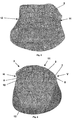
- FIG. 3 shows a plan view of the second main joint surface 2, in which in particular the convex transition from the lateral side 12 over a concavity in a convexity of the can be seen on the medial side 11, in its further course, the second main articular surface 2 falls steeply over a concavity and ends in a lateral pole.
- FIG. 4 shows the second main joint surface 2 with its curvatures from a vertical view to the main functional level.
Landscapes
- Health & Medical Sciences (AREA)
- Orthopedic Medicine & Surgery (AREA)
- Cardiology (AREA)
- Oral & Maxillofacial Surgery (AREA)
- Transplantation (AREA)
- Engineering & Computer Science (AREA)
- Biomedical Technology (AREA)
- Heart & Thoracic Surgery (AREA)
- Vascular Medicine (AREA)
- Life Sciences & Earth Sciences (AREA)
- Animal Behavior & Ethology (AREA)
- General Health & Medical Sciences (AREA)
- Public Health (AREA)
- Veterinary Medicine (AREA)
- Prostheses (AREA)
Description
- Fig.1
- eine erste Hauptgelenkfläche eines erfindungsgemäßen Gelenkes;
- Fig.2
- eine zweite Hauptgelenkfläche des Gelenkes.
Claims (17)
- Ein zum Ersatz eines oberen Sprunggelenkes bestimmtes künstliches Gelenk mit einer eine Gelenkpfanne bildenden, zum Ersatz der Tibia bestimmten ersten Hauptgelenkfläche, die aus einer zu einer der Sagittalebene entsprechenden Hauptfunktionsebene des Gelenkes parallelen, konkaven Kurvaturen aufgebaut ist, und mit einer mit der ersten Hauptgelenkfläche in Wirkverbindung tretenden zweiten Hauptgelenkfläche, als Bestandteil eines den Talus ersetzenden Gelenkkopfes mit in der Hauptfunktionsebene konvexen Kurvaturen, die auf die erste Hauptgelenkfläche abgestimmt sind, wobei die Radien der konvexen Kurvaturen der zweiten Hauptgelenkfläche kleiner als diejenigen der korrespondierenden Kurvaturen der ersten Hauptgelenkfläche bemessen sind, dadurch gekennzeichnet, dass die auftretenden Differenzbeträge der korrespondierenden Radien der ersten Hauptgelenkfläche (1) und der zweiten Hauptgelenkfläche (2) in einer nach oben weisenden Winkelstellung (V) und einer nach unten weisenden Winkelstellung (H) des Gelenkes (3) voneinander abweichen.
- Gelenk nach Anspruch 1, dadurch gekennzeichnet, dass die Radien der konvexen Kurvaturen (7, 8, 9, 10) der zweiten Hauptgelenkfläche (2) 5 - 20 % kleiner als diejenigen der korrespondierenden Kurvaturen der ersten Hauptgelenkfläche (1) bemessen sind.
- Gelenk nach den Ansprüchen 1 oder 2, dadurch gekennzeichnet, dass die Differenzbeträge der Radien zwischen einer der Körpermitte zugewandten medialen Seite (11) und einer dem Körperäußeren zugewandten lateralen Seite (12) bei übereinstimmenden Winkelstellungen (V, H) des Gelenkes (3) voneinander abweichen.
- Gelenk nach zumindest einem der vorhergehenden Ansprüche, dadurch gekennzeichnet, dass die Kurvaturen (7, 8, 9, 10) paralleler Ebenen der zweiten Hauptgelenkfläche (2) in der nach oben weisenden Winkelstellung (V) der lateralen Seite (12) zu der medialen Seite (11) des Gelenkes (3) abnehmende Radien aufweisen.
- Gelenk nach zumindest einem der vorhergehenden Ansprüche, dadurch gekennzeichnet, dass die Kurvaturen (7, 8, 9, 10) paralleler Ebenen der zweiten Hauptgelenkfläche (2) in der nach unten weisenden Winkelstellung (H) der medialen Seite (11) zu der lateralen Seite (12) des Gelenkes (3) abnehmende Radien aufweisen.
- Gelenk nach zumindest einem der vorhergehenden Ansprüche, dadurch gekennzeichnet, dass die Radien der Kurvaturen (7, 8, 9, 10) auf der lateralen Seite (12) in der nach oben weisenden Winkelstellung (V) kleiner als in der nach unten weisenden Winkelstellung (H) und auf der medialen Seite (11) in der nach oben weisenden Winkelstellung (V) größer als in der nach unten weisenden Winkelstellung (H) bemessen sind.
- Gelenk nach zumindest einem der vorhergehenden Ansprüche, dadurch gekennzeichnet, dass die Kurvaturen (7, 8, 9, 10) aus wenigen Einzelradien mit einem stetigen Übergang aufgebaut sind.
- Gelenk nach zumindest einem der vorhergehenden Ansprüche, dadurch gekennzeichnet, dass die erste Hauptgelenkfläche (1) und / oder die zweite Hauptgelenkfläche (2) quer zu der Hauptfunktionsebene in der nach vom weisenden Winkelstellung (V) breiter als in der nach unten weisenden Winkelstellung (H) ausgeführt ist.
- Gelenk nach zumindest einem der vorhergehenden Ansprüche, dadurch gekennzeichnet, dass das Größenverhältnis der ersten Hauptgelenkfläche (1) gegenüber der zweiten Hauptgelenkfläche (2) näherungsweise 2:3 beträgt.
- Gelenk nach zumindest einem der vorhergehenden Ansprüche, dadurch gekennzeichnet, dass die erste Hauptgelenkfläche (1) und / oder die zweite Hauptgelenkfläche (2) einem Oberflächenausschnitt eines rotationssymmetrischen Körpers entspricht.
- Gelenk nach Anspruch 10, dadurch gekennzeichnet, dass der Oberflächenausschnitt einem Zylinder oder einem Kegel entspricht.
- Gelenk nach Anspruch 10, dadurch gekennzeichnet, dass der Oberflächenausschnitt einem Rotationshyperboloid entspricht.
- Gelenk nach Anspruch 10, dadurch gekennzeichnet, dass der Oberflächenausschnitt von der Konvexität der medialen Seite (11) zu einer Konkavität auf der zweiten Hauptgelenkfläche (2) über eine Konvexität der lateralen Seite (12) in eine steil abfallende Konkavität übergeht, die in einen lateralen Pol mündet.
- Gelenk nach zumindest einem der vorhergehenden Ansprüche, dadurch gekennzeichnet, dass die korrespondierende erste Hauptgelenkfläche (1) eine an die zweite Hauptgelenkfläche (2) angepasste Formgebung mit einem geringfügigen Differenzmaß aufweist.
- Gelenk nach zumindest einem der vorhergehenden Ansprüche, dadurch gekennzeichnet, dass die erste Hauptgelenkfläche (1) als eine Einheit zugleich der Tibia und der Fibula zugeordnet ist.
- Gelenk nach zumindest einem der vorhergehenden Ansprüche, dadurch gekennzeichnet, dass die erste Hauptgelenkfläche (1) aus zwei Strukturelementen besteht.
- Gelenk nach Anspruch 16, dadurch gekennzeichnet, dass die beiden Strukturelemente in einer zu der Hauptfunktionsebene parallelen Ebene miteinander verbunden sind.
Applications Claiming Priority (3)
| Application Number | Priority Date | Filing Date | Title |
|---|---|---|---|
| DE10213063 | 2002-03-22 | ||
| DE10213063A DE10213063B4 (de) | 2002-03-22 | 2002-03-22 | Künstliches Gelenk |
| PCT/DE2003/000827 WO2003079938A1 (de) | 2002-03-22 | 2003-03-13 | Künstliches gelenk |
Publications (2)
| Publication Number | Publication Date |
|---|---|
| EP1489999A1 EP1489999A1 (de) | 2004-12-29 |
| EP1489999B1 true EP1489999B1 (de) | 2005-09-14 |
Family
ID=27815899
Family Applications (1)
| Application Number | Title | Priority Date | Filing Date |
|---|---|---|---|
| EP03720173A Expired - Lifetime EP1489999B1 (de) | 2002-03-22 | 2003-03-13 | Künstliches gelenk |
Country Status (5)
| Country | Link |
|---|---|
| EP (1) | EP1489999B1 (de) |
| AT (1) | ATE304334T1 (de) |
| AU (1) | AU2003223866A1 (de) |
| DE (2) | DE10213063B4 (de) |
| WO (1) | WO2003079938A1 (de) |
Cited By (1)
| Publication number | Priority date | Publication date | Assignee | Title |
|---|---|---|---|---|
| US12502281B2 (en) | 2018-04-24 | 2025-12-23 | Paragon 28, Inc. | Implants for use in total ankle replacement |
Families Citing this family (1)
| Publication number | Priority date | Publication date | Assignee | Title |
|---|---|---|---|---|
| CA2984224A1 (en) | 2014-05-12 | 2015-11-19 | Integra Lifesciences Corporation | Total ankle replacement prosthesis |
Family Cites Families (6)
| Publication number | Priority date | Publication date | Assignee | Title |
|---|---|---|---|---|
| DE2236141B2 (de) * | 1972-07-22 | 1976-07-08 | Fa. Waldemar Link, 2000 Hamburg | Teilprothese fuer das sprunggelenk eines menschen |
| US3886599A (en) * | 1974-07-25 | 1975-06-03 | Schlein Louis Charles | Surgically implantable total ankle prosthesis |
| US3975778A (en) * | 1975-07-14 | 1976-08-24 | Newton Iii St Elmo | Total ankle arthroplasty |
| DE4202717C1 (de) * | 1991-12-11 | 1993-06-17 | Dietmar Prof. Dr. 3350 Kreiensen De Kubein-Meesenburg | |
| DE19521597A1 (de) * | 1995-06-14 | 1996-12-19 | Kubein Meesenburg Dietmar | Künstliches Gelenk, insbesondere Endoprothese zum Ersatz natürlicher Gelenke |
| FR2760353B1 (fr) * | 1997-03-10 | 1999-07-02 | Tornier Sa | Prothese de cheville |
-
2002
- 2002-03-22 DE DE10213063A patent/DE10213063B4/de not_active Expired - Fee Related
-
2003
- 2003-03-13 DE DE50301195T patent/DE50301195D1/de not_active Expired - Lifetime
- 2003-03-13 AU AU2003223866A patent/AU2003223866A1/en not_active Abandoned
- 2003-03-13 EP EP03720173A patent/EP1489999B1/de not_active Expired - Lifetime
- 2003-03-13 WO PCT/DE2003/000827 patent/WO2003079938A1/de not_active Ceased
- 2003-03-13 AT AT03720173T patent/ATE304334T1/de not_active IP Right Cessation
Cited By (1)
| Publication number | Priority date | Publication date | Assignee | Title |
|---|---|---|---|---|
| US12502281B2 (en) | 2018-04-24 | 2025-12-23 | Paragon 28, Inc. | Implants for use in total ankle replacement |
Also Published As
| Publication number | Publication date |
|---|---|
| ATE304334T1 (de) | 2005-09-15 |
| AU2003223866A1 (en) | 2003-10-08 |
| DE50301195D1 (de) | 2005-10-20 |
| WO2003079938A1 (de) | 2003-10-02 |
| EP1489999A1 (de) | 2004-12-29 |
| DE10213063A1 (de) | 2003-10-09 |
| DE10213063B4 (de) | 2004-02-05 |
Similar Documents
| Publication | Publication Date | Title |
|---|---|---|
| DE69125375T2 (de) | Gelenkprothese | |
| EP0617595B1 (de) | Künstliches gelenk | |
| EP0560141B1 (de) | Bandscheibenendoprothese | |
| DE69716329T2 (de) | Knöchelprothese | |
| DE69002159T2 (de) | Biegegliedprothese. | |
| DE69922723T2 (de) | Knieprothese mit vier Gelenkflächen | |
| EP0808619B1 (de) | Ellbogengelenk-Endoprothese | |
| DE2527864C3 (de) | Gelenkendoprothese für ein Handgelenk | |
| DE4038082C2 (de) | Wirbelverbindungsanordnung | |
| EP1250898A1 (de) | Sytem von Bandscheibenprothesen | |
| EP0565216A2 (de) | Marknagel | |
| WO2005030098A1 (de) | Sprunggelenk-endoprothese | |
| DE2320683A1 (de) | Endoprothese fuer den proximalen hueftteil | |
| DE2304988A1 (de) | Kniegelenkprothese | |
| EP0442330A2 (de) | Kniegelenk-Endoprothese | |
| DE2344569B2 (de) | Schultergelenk-endoprothese | |
| DE4041920A1 (de) | Kuenstliches kniegelenk | |
| WO1999032052A1 (de) | Gelenk (kniegelenk) | |
| EP0366603A1 (de) | Blattartiger Schaft aus Metall für eine Femurkopfprothese | |
| EP1827319A1 (de) | Künstliches gelenkelement sowie ein damit ausgestattetes greifwerkzeug | |
| DE2805305C2 (de) | ||
| EP1489999B1 (de) | Künstliches gelenk | |
| EP0151724A1 (de) | Tibiateil für eine Kniegelenkprothese | |
| DE102004038281B3 (de) | Schenkelhalsprothese | |
| WO2004069103A1 (de) | Implantat |
Legal Events
| Date | Code | Title | Description |
|---|---|---|---|
| PUAI | Public reference made under article 153(3) epc to a published international application that has entered the european phase |
Free format text: ORIGINAL CODE: 0009012 |
|
| 17P | Request for examination filed |
Effective date: 20041022 |
|
| AK | Designated contracting states |
Kind code of ref document: A1 Designated state(s): AT BE BG CH CY CZ DE DK EE ES FI FR GB GR HU IE IT LI LU MC NL PT RO SE SI SK TR |
|
| AX | Request for extension of the european patent |
Extension state: AL LT LV MK |
|
| GRAP | Despatch of communication of intention to grant a patent |
Free format text: ORIGINAL CODE: EPIDOSNIGR1 |
|
| GRAS | Grant fee paid |
Free format text: ORIGINAL CODE: EPIDOSNIGR3 |
|
| GRAA | (expected) grant |
Free format text: ORIGINAL CODE: 0009210 |
|
| AK | Designated contracting states |
Kind code of ref document: B1 Designated state(s): AT BE BG CH CY CZ DE DK EE ES FI FR GB GR HU IE IT LI LU MC NL PT RO SE SI SK TR |
|
| PG25 | Lapsed in a contracting state [announced via postgrant information from national office to epo] |
Ref country code: IT Free format text: LAPSE BECAUSE OF FAILURE TO SUBMIT A TRANSLATION OF THE DESCRIPTION OR TO PAY THE FEE WITHIN THE PRESCRIBED TIME-LIMIT;WARNING: LAPSES OF ITALIAN PATENTS WITH EFFECTIVE DATE BEFORE 2007 MAY HAVE OCCURRED AT ANY TIME BEFORE 2007. THE CORRECT EFFECTIVE DATE MAY BE DIFFERENT FROM THE ONE RECORDED. Effective date: 20050914 Ref country code: NL Free format text: LAPSE BECAUSE OF FAILURE TO SUBMIT A TRANSLATION OF THE DESCRIPTION OR TO PAY THE FEE WITHIN THE PRESCRIBED TIME-LIMIT Effective date: 20050914 Ref country code: CZ Free format text: LAPSE BECAUSE OF FAILURE TO SUBMIT A TRANSLATION OF THE DESCRIPTION OR TO PAY THE FEE WITHIN THE PRESCRIBED TIME-LIMIT Effective date: 20050914 Ref country code: SK Free format text: LAPSE BECAUSE OF FAILURE TO SUBMIT A TRANSLATION OF THE DESCRIPTION OR TO PAY THE FEE WITHIN THE PRESCRIBED TIME-LIMIT Effective date: 20050914 Ref country code: RO Free format text: LAPSE BECAUSE OF FAILURE TO SUBMIT A TRANSLATION OF THE DESCRIPTION OR TO PAY THE FEE WITHIN THE PRESCRIBED TIME-LIMIT Effective date: 20050914 Ref country code: FI Free format text: LAPSE BECAUSE OF FAILURE TO SUBMIT A TRANSLATION OF THE DESCRIPTION OR TO PAY THE FEE WITHIN THE PRESCRIBED TIME-LIMIT Effective date: 20050914 Ref country code: SI Free format text: LAPSE BECAUSE OF FAILURE TO SUBMIT A TRANSLATION OF THE DESCRIPTION OR TO PAY THE FEE WITHIN THE PRESCRIBED TIME-LIMIT Effective date: 20050914 Ref country code: IE Free format text: LAPSE BECAUSE OF FAILURE TO SUBMIT A TRANSLATION OF THE DESCRIPTION OR TO PAY THE FEE WITHIN THE PRESCRIBED TIME-LIMIT Effective date: 20050914 |
|
| REG | Reference to a national code |
Ref country code: GB Ref legal event code: FG4D Free format text: NOT ENGLISH |
|
| REG | Reference to a national code |
Ref country code: CH Ref legal event code: EP |
|
| REG | Reference to a national code |
Ref country code: IE Ref legal event code: FG4D Free format text: LANGUAGE OF EP DOCUMENT: GERMAN |
|
| REF | Corresponds to: |
Ref document number: 50301195 Country of ref document: DE Date of ref document: 20051020 Kind code of ref document: P |
|
| PG25 | Lapsed in a contracting state [announced via postgrant information from national office to epo] |
Ref country code: SE Free format text: LAPSE BECAUSE OF FAILURE TO SUBMIT A TRANSLATION OF THE DESCRIPTION OR TO PAY THE FEE WITHIN THE PRESCRIBED TIME-LIMIT Effective date: 20051214 Ref country code: GR Free format text: LAPSE BECAUSE OF FAILURE TO SUBMIT A TRANSLATION OF THE DESCRIPTION OR TO PAY THE FEE WITHIN THE PRESCRIBED TIME-LIMIT Effective date: 20051214 Ref country code: BG Free format text: LAPSE BECAUSE OF FAILURE TO SUBMIT A TRANSLATION OF THE DESCRIPTION OR TO PAY THE FEE WITHIN THE PRESCRIBED TIME-LIMIT Effective date: 20051214 Ref country code: DK Free format text: LAPSE BECAUSE OF FAILURE TO SUBMIT A TRANSLATION OF THE DESCRIPTION OR TO PAY THE FEE WITHIN THE PRESCRIBED TIME-LIMIT Effective date: 20051214 |
|
| PG25 | Lapsed in a contracting state [announced via postgrant information from national office to epo] |
Ref country code: ES Free format text: LAPSE BECAUSE OF FAILURE TO SUBMIT A TRANSLATION OF THE DESCRIPTION OR TO PAY THE FEE WITHIN THE PRESCRIBED TIME-LIMIT Effective date: 20051225 |
|
| REG | Reference to a national code |
Ref country code: CH Ref legal event code: PFA Owner name: AEQUOS ENDOPROTHETIK GMBH Free format text: HJS GELENK SYSTEM GMBH#MAUERKIRCHERSTRASSE 180#81925 MUENCHEN (DE) -TRANSFER TO- AEQUOS ENDOPROTHETIK GMBH#MAUERKIRCHER STRASSE 180#81925 MUENCHEN (DE) Ref country code: CH Ref legal event code: NV Representative=s name: TROESCH SCHEIDEGGER WERNER AG |
|
| GBT | Gb: translation of ep patent filed (gb section 77(6)(a)/1977) |
Effective date: 20060105 |
|
| PG25 | Lapsed in a contracting state [announced via postgrant information from national office to epo] |
Ref country code: PT Free format text: LAPSE BECAUSE OF FAILURE TO SUBMIT A TRANSLATION OF THE DESCRIPTION OR TO PAY THE FEE WITHIN THE PRESCRIBED TIME-LIMIT Effective date: 20060214 |
|
| NLV1 | Nl: lapsed or annulled due to failure to fulfill the requirements of art. 29p and 29m of the patents act | ||
| PG25 | Lapsed in a contracting state [announced via postgrant information from national office to epo] |
Ref country code: AT Free format text: LAPSE BECAUSE OF NON-PAYMENT OF DUE FEES Effective date: 20060313 |
|
| PG25 | Lapsed in a contracting state [announced via postgrant information from national office to epo] |
Ref country code: HU Free format text: LAPSE BECAUSE OF FAILURE TO SUBMIT A TRANSLATION OF THE DESCRIPTION OR TO PAY THE FEE WITHIN THE PRESCRIBED TIME-LIMIT Effective date: 20060315 |
|
| PG25 | Lapsed in a contracting state [announced via postgrant information from national office to epo] |
Ref country code: LU Free format text: LAPSE BECAUSE OF NON-PAYMENT OF DUE FEES Effective date: 20060331 Ref country code: MC Free format text: LAPSE BECAUSE OF NON-PAYMENT OF DUE FEES Effective date: 20060331 Ref country code: BE Free format text: LAPSE BECAUSE OF NON-PAYMENT OF DUE FEES Effective date: 20060331 |
|
| REG | Reference to a national code |
Ref country code: IE Ref legal event code: FD4D |
|
| ET | Fr: translation filed | ||
| PLBE | No opposition filed within time limit |
Free format text: ORIGINAL CODE: 0009261 |
|
| STAA | Information on the status of an ep patent application or granted ep patent |
Free format text: STATUS: NO OPPOSITION FILED WITHIN TIME LIMIT |
|
| 26N | No opposition filed |
Effective date: 20060615 |
|
| BERE | Be: lapsed |
Owner name: HJS GELENK SYSTEM G.M.B.H. Effective date: 20060331 |
|
| PG25 | Lapsed in a contracting state [announced via postgrant information from national office to epo] |
Ref country code: EE Free format text: LAPSE BECAUSE OF FAILURE TO SUBMIT A TRANSLATION OF THE DESCRIPTION OR TO PAY THE FEE WITHIN THE PRESCRIBED TIME-LIMIT Effective date: 20050914 |
|
| PG25 | Lapsed in a contracting state [announced via postgrant information from national office to epo] |
Ref country code: TR Free format text: LAPSE BECAUSE OF FAILURE TO SUBMIT A TRANSLATION OF THE DESCRIPTION OR TO PAY THE FEE WITHIN THE PRESCRIBED TIME-LIMIT Effective date: 20050914 |
|
| PG25 | Lapsed in a contracting state [announced via postgrant information from national office to epo] |
Ref country code: CY Free format text: LAPSE BECAUSE OF FAILURE TO SUBMIT A TRANSLATION OF THE DESCRIPTION OR TO PAY THE FEE WITHIN THE PRESCRIBED TIME-LIMIT Effective date: 20050914 |
|
| PGFP | Annual fee paid to national office [announced via postgrant information from national office to epo] |
Ref country code: CH Payment date: 20100325 Year of fee payment: 8 |
|
| PGFP | Annual fee paid to national office [announced via postgrant information from national office to epo] |
Ref country code: FR Payment date: 20100331 Year of fee payment: 8 |
|
| PGFP | Annual fee paid to national office [announced via postgrant information from national office to epo] |
Ref country code: GB Payment date: 20100324 Year of fee payment: 8 |
|
| PGFP | Annual fee paid to national office [announced via postgrant information from national office to epo] |
Ref country code: DE Payment date: 20100331 Year of fee payment: 8 |
|
| REG | Reference to a national code |
Ref country code: CH Ref legal event code: PL |
|
| GBPC | Gb: european patent ceased through non-payment of renewal fee |
Effective date: 20110313 |
|
| REG | Reference to a national code |
Ref country code: FR Ref legal event code: ST Effective date: 20111130 |
|
| PG25 | Lapsed in a contracting state [announced via postgrant information from national office to epo] |
Ref country code: CH Free format text: LAPSE BECAUSE OF NON-PAYMENT OF DUE FEES Effective date: 20110331 Ref country code: DE Free format text: LAPSE BECAUSE OF NON-PAYMENT OF DUE FEES Effective date: 20111001 Ref country code: FR Free format text: LAPSE BECAUSE OF NON-PAYMENT OF DUE FEES Effective date: 20110331 Ref country code: LI Free format text: LAPSE BECAUSE OF NON-PAYMENT OF DUE FEES Effective date: 20110331 |
|
| REG | Reference to a national code |
Ref country code: DE Ref legal event code: R119 Ref document number: 50301195 Country of ref document: DE Effective date: 20111001 |
|
| PG25 | Lapsed in a contracting state [announced via postgrant information from national office to epo] |
Ref country code: GB Free format text: LAPSE BECAUSE OF NON-PAYMENT OF DUE FEES Effective date: 20110313 |