EP1489885A2 - Method for operating a hearing aid system as well as a hearing aid system with a microphone system in which different directional characteristics are selectable - Google Patents
Method for operating a hearing aid system as well as a hearing aid system with a microphone system in which different directional characteristics are selectable Download PDFInfo
- Publication number
- EP1489885A2 EP1489885A2 EP04013290A EP04013290A EP1489885A2 EP 1489885 A2 EP1489885 A2 EP 1489885A2 EP 04013290 A EP04013290 A EP 04013290A EP 04013290 A EP04013290 A EP 04013290A EP 1489885 A2 EP1489885 A2 EP 1489885A2
- Authority
- EP
- European Patent Office
- Prior art keywords
- microphone
- hearing aid
- signal
- hearing
- frequency
- Prior art date
- Legal status (The legal status is an assumption and is not a legal conclusion. Google has not performed a legal analysis and makes no representation as to the accuracy of the status listed.)
- Granted
Links
Images

Classifications
-
- H—ELECTRICITY
- H04—ELECTRIC COMMUNICATION TECHNIQUE
- H04R—LOUDSPEAKERS, MICROPHONES, GRAMOPHONE PICK-UPS OR LIKE ACOUSTIC ELECTROMECHANICAL TRANSDUCERS; DEAF-AID SETS; PUBLIC ADDRESS SYSTEMS
- H04R25/00—Deaf-aid sets, i.e. electro-acoustic or electro-mechanical hearing aids; Electric tinnitus maskers providing an auditory perception
- H04R25/40—Arrangements for obtaining a desired directivity characteristic
- H04R25/407—Circuits for combining signals of a plurality of transducers
-
- H—ELECTRICITY
- H04—ELECTRIC COMMUNICATION TECHNIQUE
- H04R—LOUDSPEAKERS, MICROPHONES, GRAMOPHONE PICK-UPS OR LIKE ACOUSTIC ELECTROMECHANICAL TRANSDUCERS; DEAF-AID SETS; PUBLIC ADDRESS SYSTEMS
- H04R25/00—Deaf-aid sets, i.e. electro-acoustic or electro-mechanical hearing aids; Electric tinnitus maskers providing an auditory perception
- H04R25/70—Adaptation of deaf aid to hearing loss, e.g. initial electronic fitting
-
- H—ELECTRICITY
- H04—ELECTRIC COMMUNICATION TECHNIQUE
- H04R—LOUDSPEAKERS, MICROPHONES, GRAMOPHONE PICK-UPS OR LIKE ACOUSTIC ELECTROMECHANICAL TRANSDUCERS; DEAF-AID SETS; PUBLIC ADDRESS SYSTEMS
- H04R2225/00—Details of deaf aids covered by H04R25/00, not provided for in any of its subgroups
- H04R2225/41—Detection or adaptation of hearing aid parameters or programs to listening situation, e.g. pub, forest
Definitions
- the invention relates to a method for setting a hearing aid and a hearing aid with a microphone system with variable directional characteristic for recording an acoustic Input signal and output of at least one microphone signal, a signal processing unit and an output transducer. Furthermore, the invention relates to a programming device for a hearing aid.
- the classification may include u.a. influence have on the operation of noise canceling algorithms as well as on the microphone system. For example selected depending on the detected hearing situation (discretely switched or continuously faded) between a omnidirectional directional characteristic (directional characteristic zeroth order) and a clear directivity of the microphone system (Directivity of first or higher order).
- a omnidirectional directional characteristic directional characteristic zeroth order
- a clear directivity of the microphone system Directivity of first or higher order.
- Such microphone systems show a frequency-dependent transmission behavior, in which a significant drop to low frequencies is recorded.
- the noise behavior of the microphones is frequency independent.
- a hearing aid is known with a Signal processing unit and at least two microphones, the different for the formation of directional microphone systems Order can be interconnected, with the directional microphone systems in turn, in the frequency of the Microphones emitted microphone signals dependent weighting interconnected with each other.
- the cutoff frequency between adjacent Frequency bands where a different Weighting of the microphone signals is provided set become.
- EP 0 942 627 A2 is a hearing aid with directional microphone system with a signal processing device, a handset and several microphones whose output signals for Generation of an individual directional microphone characteristic over Delay devices and the signal processing device interconnected in different weightings are.
- the preferred Receiving direction (main direction) in adaptation to a present hearing situation can be set individually.
- the microphone signal of the directional Microphones will be in the range of low signal frequencies in its Amplified amplitude and the microphone signal of the omnidirectional Aligned to microphones. Both the microphone signal of the omnidirectional microphones as well as the microphone signal of the Directional microphones are fed to a switching unit. In a first switching position of the switching unit is omnidirectional microphone and in a second switching position the switching unit the directional microphone with a hearing aid amplifier connected. The switching unit can be dependent on the signal level of a microphone signal automatically switch.
- a disadvantage of the known hearing aid devices with a directional microphone system is that in certain listening situations either the directivity of the microphone system is not optimally used or that a high degree of directivity becomes one clearly audible deterioration of the sound quality.
- the object of the present invention is to improve the sound quality a hearing aid with directional microphone system to improve.
- the hearing aid according to the invention comprises a microphone system with at least two microphones, for directional characteristics to realize zeroth and first order. Preferably however, more than two microphones are present, so that Also directional characteristics of second and higher order possible are.
- the hearing aid device comprises a signal processing unit for processing and frequency-dependent Amplification of the microphone signal generated by the microphone system.
- the signal output is usually by an acoustic Output signal by means of a handset. But they are others, e.g. Vibrating output transducer known.
- a directional characteristic of zero order in the context of the invention is an omnidirectional directional characteristic to understand for example, a single, not with others Microphones interconnected omnidirectional microphone emerges.
- a microphone unit with a directional characteristic first order (directional microphone first order), for example through a single gradient microphone or the electric Interconnection of two omnidirectional microphones realized become.
- directional microphones of the first order is a theoretical one achievable maximum value of the Miniiviti Index (DI) of 6 dB (hypercardioid).
- DI Cosmeticiviti Index
- Directional microphones second and higher order have DI values of 10 dB and more, for example, for better speech intelligibility are advantageous. Does a hearing aid include a microphone system? with for example three omnidirectional microphones, so can be based on this by appropriate interconnection of the microphones simultaneously microphone units with directional characteristics zeroth to second order can be realized.
- a single omnidirectional microphone makes a difference Microphone unit zeroth order dar. Will with two omnidirectional Microphones delay the microphone signal of a microphone, inverted and to the microphone signal of the other microphone adds, it creates a microphone unit of the first order. Will turn with two microphone units first order the microphone signal of a microphone unit delayed, inverted and to the microphone signal of the second microphone unit added first order, this results in a microphone unit with directional characteristic of second order. Let that way depending on the number of omnidirectional microphones - Implement microphone units of any order.
- a microphone system include different microphone units Order, so can between different directional characteristics be switched over, e.g. by switching on or off one or more microphones. Furthermore, by a suitable electrical connection of the microphone units also any mixed forms between the directional characteristics different order are generated. For this purpose, the Microphone signals of the microphone units weighted differently and added before being in the signal processing unit the hearing aid is further processed and amplified. So can a continuous, smooth transition between different directional characteristics are realized, which avoids disturbing artifacts when switching to let.
- the approved Microphone noise to the individual hearing loss of Hearing aid wearer adapted by having a change the directional characteristic only to the extent permitted microphone noise in which this is not done by the hearing aid wearer is distracting.
- On the other hand is at a loud Output signal of the hearing aid, the microphone noise hidden and therefore inaudible. Therefore, in situations with a relatively high signal level of the microphone system generated microphone signal the directivity due to the psychoacoustic Masking of the microphone noise by the loud Input signal can not be restricted.
- the individual rest hearing threshold of the hearing aid wearer the setting of the directivity to take into account.
- the rest hearing threshold of the hearing aid wearer depending on the frequency of the hearing of the Hearing aid carrier supplied test signal determined. Based current hearing aid settings, in particular the signal transmission behavior of the hearing aid and the Concerning the microphone system, this can be done by the microphone system outgoing and the hearing of the hearing aid wearer supplied Microphone noise over the frequency is calculated fairly accurately become. As an alternative to the calculation, it is also possible, the microphone noise under the given settings of the hearing aid as a function of the frequency measure up. A comparison with the previously measured individual Rest hearing threshold of the hearing aid wearer now shows whether the Microphone noise at least in certain frequency ranges above the rest hearing threshold and thus by the hearing aid wearer is perceived. According to the invention is then for the transferable with the hearing aid frequencies as possible high level of directivity adjusted without doing so the microphone noise caused by the microphone system Silence threshold exceeds.
- the directional characteristic of the microphone system adjusted so that the of the Microphone system and the hearing aid wearer's hearing supplied microphone noise at least in a certain Frequency range though above the rest hearing threshold is, but one of the hearing aid wearer individual does not exceed what is considered tolerable.
- the Microphone noise can be adjusted so that this at least approximately over the entire, transferable by the hearing aid Frequency range with the rest hearing threshold or the tolerable level of noise.
- An embodiment of the invention provides that the adjustment of the directional microphone system during operation of the Hearing aid adapted to the current environment becomes.
- a microphone signal with high Signal level allowed a higher level of directivity than this alone taking into account the threshold of hearing loss Case would be.
- this requires the signal level of the microphone signal generated by the microphone system to eat.
- An optimization of the directivity is in particular then reached when the individual masking threshold the Hörzzowski mars determined with respect to the microphone noise becomes. This indicates at which signal level a from an acoustic input signal originating in the output signal of the microphone system, the proportion of microphone noise masked in this output, i. concealed and thus no longer perceptible by the hearing aid wearer is.
- the masking threshold depends on the frequency and the signal level of the microphone noise and indicates which Microphone signals are suitable to the microphone noise cover.
- the degree of directivity of the microphone system is then varies such that, depending on the frequency of a Acoustic input signal as high as possible directivity is achieved without causing the microphone noise the Mask michsschelle exceeds.
- Analogous to the rest hearing threshold can also be one of the hearing aid wearer individually tolerated as tolerated level of microphone noise allowed be, which means that the directivity adjusted is that the microphone noise at least in a certain Frequency range also the masking threshold may exceed certain measure.
- any function which specifies the value of the microphone noise depending on the frequency the rest hearing threshold should exceed or fall short of.
- the adjustment of the directivity of the hearing aid according to of the invention as a function of the rest hearing threshold or the masking threshold may be, for example, during adaptation the hearing aid to the individual hearing loss a hearing aid wearer carried by the acoustician.
- this adaptation takes place automatically the programming device, controlled by an appropriate programming software.
- the programmer calculates these data then values of the setting parameters affecting the setting the directivity as a function of frequency affect.
- the setting of Directivity additionally dependent on the signal level of the Output signal supplied to the hearing of the hearing aid wearer becomes. Also in this regard are by the programmer Setting parameters calculated and on the hearing aid transmit the directivity of the microphone system in Dependence of this signal level during operation of the hearing aid.
- the invention can be used in all known hearing aid types be applied with an adjustable directional microphone, for example for hearing aids worn behind the ear, in ear hearing aids, implantable hearing aids or pocket hearing aids.
- the hearing aid according to the invention also part of a plurality of devices for the care of a hard hearing aid comprehensive hearing aid system be, e.g. Part of a hearing aid system with two am Head worn hearing aids for binaural care or Part of a hearing aid system, consisting of one on the head portable device and a wearable processor unit.
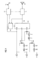
- FIG. 1 shows a schematic diagram of a hearing aid with a directional microphone system according to the invention.
- the microphone system includes three omnidirectional microphones 1, 2 and 3.
- the emanating from the microphone 2 microphone signal is in a Delay unit 4A delayed by an inverter 5A inverted and in a summer 6A to that of the microphone 1 outgoing microphone signal R0 added.
- the two omnidirectional Microphones 1 and 2 thereby form a directional microphone 1, 2 with directivity of the first order, of which the Microphone signal R1 goes off.
- that of the microphone 3 outgoing microphone signal in a 4B delay unit delayed, inverted by an inverter 5B and in one Summer 6B to the outgoing from the microphone 2 microphone signal added.
- the microphones 2 and 3 form by a Directional microphone system 2, 3 with directivity of the first order, whose microphone signal is present at the output of the summer 6B. Will in turn that of the directional microphone system 2, 3 outgoing microphone signal in a delay unit 7 delayed and inverted in an inverter 8 and in a summer 9 to that emanating from the directional microphone system 1, 2 Microphone signal R1 added, it arises from the microphones 1, 2 and 3, a directional microphone system 1, 2, 3 with directional characteristics second order, the microphone signal R2 at the output of Totalizer 9 is present.
- the three microphone signals R0, R1 and R2 are finally fed to a circuit unit 10 in which Switched between the different microphone signals can be or in the different microphone signals R0, R1 and R2 are weighted differently and added together.
- the resulting and output at the output of the circuit unit 10 Microphone output RA finally becomes one Signal processing unit 11 is supplied in the further processing and frequency dependent amplification of the microphone output signal RA to compensate for the individual hearing loss a hearing aid wearer takes place.
- Signal processing unit 11 is supplied in the further processing and frequency dependent amplification of the microphone output signal RA to compensate for the individual hearing loss a hearing aid wearer takes place.
- microphone signal for delivery into an ear canal of the Hearing aid carrier by a handset 12 in an acoustic Signal changed.
- Modern hearing aids can be in a special way to different Adjust listening situations.
- a control unit 13 in the different parameter sets, so-called listening programs, for controlling the signal processing in the hearing aid can be stored and retrieved. Between the different ones Listening programs can be switched by means of a program selection button 14 become.
- the hearing aid has a Automatic situation detection, by means of which the signal processing relevant parameters of the hearing aid adjusted during operation of the hearing aid can be.
- the control unit 13 is the from the omnidirectional microphone 1 outgoing microphone signal fed. Also the directional characteristic of the microphone system is to the detected environmental situation or to the set Hearing program adapted, in the embodiment a microphone control unit 15 is provided which also is controlled by the control unit 13.
- the microphone control unit 15 Depends on the recognized environment situation or the selected hearing program can thus via the microphone control unit 15 between Directional microphone systems with directivity zeroth, first or second order or it can be the emanating from the directional microphones of different order Microphone signals controlled by the microphone control unit 15, weighted and added differently.
- the adjustment of the directivity under Consideration of the individual rest hearing threshold of a hearing aid wearer he follows. This is through an auditory test which is usually determined by a hearing care professional is carried out. Further, in the hearing aid according to the embodiment, the microphone noise for different Directional characteristics determined, e.g. measured or under Consideration of the microphone characteristics, the different Interconnections of the microphones and the signal processing in the hearing aid at the respective hearing aid settings calculated. Subsequently, at the hearing aid the directivity as a function of frequency, the rest hearing threshold as well as the microphone noise at the respective Frequency set.
- the directional characteristic is set that generated by the microphone system and the hearing of the Hearing aid carrier supplied microphone noise on the order
- This rest threshold is, so that a possible high level of directivity is achieved without doing so the microphone noise generated by the microphone system is perceived by the hearing aid wearer as disturbing.
- the hearing aid wearer e.g. at 50dB SPL, so may in this Frequency range a higher degree of directivity allowed be, for example, a directional second Order, without causing the microphone noise from the hearing aid wearer is perceived.
- Another strategy of hearing aid setup may be in it exist that perceptible by the hearing aid wearer Microphone noise does not exceed a certain level.
- the microphone system is then adjusted so that in the output signal the hearing aid from that of the microphone system caused microphone noise at most by just this measure exceeds the rest hearing threshold of the hearing aid wearer.
- This may be tolerated by the hearing aid wearer considered levels of microphone noise throughout, relate by the hearing aid transmittable frequency range or only to a specific frequency range.
- a further development of the invention provides that the microphone control unit 15 also the output signal of the control unit 10 and thus the intended for further processing microphone output signal RA is supplied.
- This has the advantage that in addition to the individual rest threshold and the signal level this microphone signal when setting the directional characteristic can be taken into account.
- the microphone noise namely only at relatively low signal levels this microphone output signal RA perceived as disturbing.
- This microphone output signal RA takes the microphone noise only a small Share of this signal and the overwhelming share of the microphone output signal RA is determined by the acoustic input signal certainly.
- this causes the microphone noise anyway hidden by the acoustic input signal (masked) and thus by the hearing aid wearer is not perceived.
- the individual Masking threshold determined for the microphone noise becomes. Then the directivity depending on the frequency the outgoing of the microphones 1-3 microphone signals R0, R1 and R2 are set so that always the maximum directivity is set at which the microphone noise is straight is still hidden. In the case of a very quiet acoustic Input signal or without acoustic input signal is then automatically at least essentially only that of the omnidirectional microphone 1 outgoing microphone signal R0 on the signal processing unit 11 forwarded. With increasing Signal level in the microphone signal then becomes stepwise switched to directional characteristics of higher order or continuously the weight of the microphone signal R1 or R2 increased over R0.
- the masking threshold can also be taken into account the masking threshold a certain level of microphone noise from the individual hearing aid wearer as be tolerated. Then the directional characteristic of the microphone system adjusted to that degree Microphone noise either over the entire transmittable Frequency range or only in at least one frequency band remains perceptible by the hearing aid wearer.
- the microphone control unit 15 the microphone output RA supplied to adjust the directivity of the microphone system so that the microphone noise supplied to the hearing aid wearer's hearing lies below the rest hearing threshold or by a Payload is hidden. Since the feedback thus before the actual signal processing in the hearing aid by means of Signal processing unit 11 takes place are the microphone control unit 15 also the current control parameters fed to the control unit 13, so that the further processing of the microphone output signal RA by the signal processing unit 11 can be considered. Alternatively could the microphone control unit 15 and the output signal of the signal processing unit 11 are supplied.
- the signal processing in the hearing aid according to the embodiment can be in analog, digital or in combined Circuit technology done. Furthermore, the signal processing also in parallel in adjoining frequency bands (Channels). Preferably also takes place the adjustment of the directional characteristic of the microphone system in frequency bands.
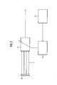
- FIG. 2 shows a block diagram for setting a directional microphone system under consideration an individual rest hearing threshold.
- the microphone system of the Hearing aid includes a microphone array 20 with multiple Microphones, each of which emit a microphone signal becomes.
- a circuit unit 21 is supplied to adjust the directional characteristics. This supplies at its signal output a microphone signal, which for further processing is provided in the hearing aid.
- goal of Hearing aid setting is to the highest possible level To achieve directivity, without the microphone noise to rise so that this from a hearing aid wearer is distracting.
- the individual rest threshold of the Hearing aid wearer depending on the frequency of the Hearing of the hearing aid wearer supplied test signal determined and stored in a storage device 22.
- the Measurement of the rest hearing threshold can be done by a hearing care professional but they can also be done with one suitable measuring equipment (PC with appropriate software) or a hearing aid with integrated tone generator of the hearing aid wearer himself be carried out.
- PC measuring equipment
- a hearing aid with integrated tone generator of the hearing aid wearer himself Is the individual rest hearing threshold of a hearing aid wearer in Dependence of the frequency is known, it can also be the required amplification of quiet input signals in dependence determine from the frequency by the hearing aid, to compensate for the hearing loss.
- hearing loss due to the hearing aid is not complete balanced, but based on the quiet hearing threshold of a Normal hearing only reduced by, for example, 50%. From the necessary amplification of quiet input signals in turn This can be the ear of the hearing aid wearer supplied Microphone noise with quiet input signals or in the absence an acoustic input signal can be determined.
- To the Determine the microphone noise as a function of the frequency and different settings with respect to the directional characteristic be either measurements on the hearing aid carried out or the respective microphone noise is based Hearing aid and microphone characteristics calculated.
- the adjustment of the hearing aid is done and in particular, the circuit unit 21 such that the Microphone noise supplied to the hearing aid wearer's hearing at least approximately coincident with its rest hearing threshold or at least does not exceed them.
- the directivity of the microphone array can also be adjusted in this way be that the resulting microphone noise at least in a certain frequency range, the rest hearing threshold of the hearing aid wearer exceeds a tolerable by this measure.
- this dimension is dependent on the Frequency freely selectable.
- the directivity is then at least in this frequency range is increased until the proportion of microphone noise in the output signal just through the from the acoustic input signal resulting proportion of Output signal is obscured or the maximum directivity is reached. This ensures that always the maximum Directivity is set at which the microphone noise not perceived as disturbing.
- the masking threshold for the microphone noise is determined by test signals detected, which corresponds to the hearing aid wearer's hearing, e.g. be supplied during the adaptation of the hearing aid. Sine signals, white noise, are preferred as test signals or a noise similar to microphone noise. Data on the measured, individual masking threshold depending on the frequency are then in one Memory device 32 stored in the hearing aid.
- a Calculator 33 calculates from these data and the output signal the circuit unit 31 adaptively optimized Adjustment of the circuit unit 31, so that much directivity is set as possible and still no microphone noise is perceived by the hearing aid wearer. Also in this embodiment, one can have an alternative Realize embodiment in that the directivity of the microphone array is set so that the resulting Microphone noise at least in a certain frequency range the resting hearing threshold of the hearing aid wearer exceeds a tolerable by this measure. Preferably also this measure depending on the frequency freely selectable.
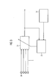
- FIG. 4 Another embodiment for adjusting the directivity a microphone system with multiple microphones 40 shows figure 4. Again, the setting is the same as the previous one Embodiment adaptive taking into account the individual Masking threshold. In contrast to the embodiment according to FIG. 3, however, this is for further processing in a signal processing unit of the hearing aid provided output signal of a circuit unit 41 not taken into account.
- the microphone system includes instead a second circuit unit 42, in which also the from the omnidirectional microphones 40 generated microphone signals and from which the intended for further processing Output signal of the microphone system is apparent.
- the settings of the first circuit unit 41 are static, That is, they are at best in the adaptation of the hearing aid, but not during normal operation set.
- the output signal of this first circuit unit 41 is then combined with the data regarding the individual Masking threshold of the hearing aid wearer, which in a storage device 43 deposited in the hearing aid used to connect the second circuit unit 42 Taxes.
- the microphone noise from the acoustic input signal could be obscured, so in the adaptive circuit unit 42 set a higher level of directivity become.
- the adjustment parameters of the circuit unit 42 become during the ongoing operation of the hearing aid from stored in the memory device 43 history of Masking threshold as a function of the frequency and the signal level the microphone noise and the useful signal and the Output signal of the circuit unit 41 by means of the computing device 44 determined.
- the degree of occlusion i. the difference the signal level of the microphone noise compared to the signal level of the originating from the acoustic input signal Proportion in the output signal of the circuit unit 41, with considered.
- the computing device 44 at the Circuit unit 42 a relatively large increase in Directivity with respect to the generated by the circuit unit 41 Directivity can be adjusted.
- the advantage of this Embodiment is that a feedback loop as in the previous embodiment is avoided.
- the adaptive adjustment of a directional microphone system according to The invention is also based on a masking model, the based on measurements on a large number of subjects.
- the Memory devices 32 and 43 of the embodiments according to Figures 3 and 4 are then data relating to this general Masking model filed in the calculation of setting parameters of the directional microphone system in the rule also gives good results.
- the elaborate measurement of individual masking threshold can be omitted.
- the invention proposes Before that, the setting of the microphone system static or Adaptive taking into account the individual rest threshold or taking into account the individual masking threshold for the microphone noise generated by the microphone system he follows. Thus, always the greatest possible degree be approved to directivity, without causing the hearing aid wearer the microphone noise generated by the microphone system as disturbing.
Landscapes
- Health & Medical Sciences (AREA)
- General Health & Medical Sciences (AREA)
- Neurosurgery (AREA)
- Otolaryngology (AREA)
- Physics & Mathematics (AREA)
- Engineering & Computer Science (AREA)
- Acoustics & Sound (AREA)
- Signal Processing (AREA)
- Circuit For Audible Band Transducer (AREA)
Abstract
Description
Verfahren zum Betrieb eines Hörhilfegerätes sowie Hörhilfegerät mit einem Mikrofonsystem, bei dem unterschiedliche Richtcharakteristiken einstellbar sindMethod for operating a hearing aid and hearing aid with a microphone system with different directional characteristics are adjustable
Die Erfindung betrifft Verfahren zum Einstellen eines Hörhilfegerätes sowie ein Hörhilfegerät mit einem Mikrofonsystem mit veränderbarer Richtcharakteristik zur Aufnahme eines akustischen Eingangssignals und Abgabe wenigstens eines Mikrofonsignals, einer Signalverarbeitungseinheit und einem Ausgangswandler. Ferner betrifft die Erfindung ein Programmiergerät für ein Hörhilfegerät.The invention relates to a method for setting a hearing aid and a hearing aid with a microphone system with variable directional characteristic for recording an acoustic Input signal and output of at least one microphone signal, a signal processing unit and an output transducer. Furthermore, the invention relates to a programming device for a hearing aid.
In modernen Hörhilfegeräten finden Einrichtungen zur Klassifikation von Hörsituationen Verwendung. Je nach Hörsituation werden die Übertragungsparameter des Hörhilfegerätes automatisch variiert. Dabei kann die Klassifikation u.a. Einfluss haben auf die Wirkungsweise von Störgeräuschunterdrückungsalgorithmen als auch auf das Mikrofonsystem. So wird beispielsweise je nach erkannter Hörsituation gewählt (diskret umgeschaltet bzw. kontinuierlich übergeblendet) zwischen einer omnidirektionalen Richtcharakteristik (Richtcharakteristik nullter Ordnung) und einer deutlichen Richtwirkung des Mikrofonsystems (Richtcharakteristik erster oder höherer Ordnung). Zur Erzeugung der Richtcharakteristik werden Gradientenmikrofone verwendet oder mehrere omnidirektionale Mikrofone elektrisch miteinander verschaltet. Derartige Mikrofonsysteme zeigen ein frequenzabhängiges Übertragungsverhalten, bei dem ein deutlicher Abfall zu tiefen Frequenzen zu verzeichnen ist. Das Rauschverhalten der Mikrofone ist dagegen frequenzunabhängig. Zum Erreichen eines natürlichen Klangeindrucks muss der Hochpassfrequenzgang des Mikrofonsystems durch Verstärkung der tiefen Frequenzen ausgeglichen werden. Dabei wird das im tiefen Frequenzbereich vorhandene Rauschen ebenfalls mitverstärkt und unter Umständen deutlich und störend hörbar, während leise Geräusche vom Rauschen verdeckt werden. Weiterhin ist bei einem aus mehreren omnidirektionalen Mikrofonen aufgebauten Mikrofonsystem das Mikrofonrauschen gegenüber einem einzelnen omnidirektionalen Mikrofon erhöht, wobei das Mikrofonrauschen mit der Anzahl der verwendeten omnidirektionalen Mikrofone zunimmt.In modern hearing aids find facilities for classification of listening situations use. Depending on the listening situation the transmission parameters of the hearing aid become automatic varied. The classification may include u.a. influence have on the operation of noise canceling algorithms as well as on the microphone system. For example selected depending on the detected hearing situation (discretely switched or continuously faded) between a omnidirectional directional characteristic (directional characteristic zeroth order) and a clear directivity of the microphone system (Directivity of first or higher order). To generate the directional characteristic gradient microphones used or multiple omnidirectional microphones electrically interconnected with each other. Such microphone systems show a frequency-dependent transmission behavior, in which a significant drop to low frequencies is recorded. The noise behavior of the microphones is frequency independent. To achieve a natural sound impression must the high pass frequency response of the microphone system by amplification the low frequencies are compensated. It will the noise present in the low frequency range as well mitverstärkt and under certain circumstances clearly and disturbingly audible, while quiet noises are covered by the noise. Farther is one of several omnidirectional microphones built microphone system, the microphone noise compared to a single omnidirectional microphone increases, the Microphone noise with the number of omnidirectional used Microphones increases.
Aus der WO 00/76268 A2 ist ein Hörhilfegerät bekannt mit einer Signalverarbeitungseinheit und mindestens zwei Mikrofonen, die zur Bildung von Richtmikrofonsystemen unterschiedlicher Ordnung miteinander verschaltbar sind, wobei die Richtmikrofonsysteme ihrerseits in von der Frequenz der von den Mikrofonen abgegebenen Mikrofonsignale abhängiger Gewichtung miteinander verschaltbar sind. In Abhängigkeit des Ergebnisses einer Signalanalyse kann die Grenzfrequenz zwischen benachbarten Frequenzbändern, bei denen eine unterschiedliche Gewichtung der Mikrofonsignale vorgesehen ist, eingestellt werden.From WO 00/76268 A2 a hearing aid is known with a Signal processing unit and at least two microphones, the different for the formation of directional microphone systems Order can be interconnected, with the directional microphone systems in turn, in the frequency of the Microphones emitted microphone signals dependent weighting interconnected with each other. Depending on the result a signal analysis, the cutoff frequency between adjacent Frequency bands where a different Weighting of the microphone signals is provided, set become.
Aus der EP 0 942 627 A2 ist ein Hörgerät mit Richtmikrofon-System mit einer Signalverarbeitungseinrichtung, einem Hörer und mehreren Mikrofonen bekannt, deren Ausgangssignale zur Erzeugung einer individuellen Richtmikrofoncharakteristik über Verzögerungseinrichtungen und die Signalverarbeitungseinrichtung in unterschiedlicher Gewichtung miteinander verschaltbar sind. Bei dem Richtmikrofon-System kann die bevorzugte Empfangsrichtung (Hauptrichtung) in Anpassung an eine vorliegende Hörsituation individuell eingestellt werden.From EP 0 942 627 A2 is a hearing aid with directional microphone system with a signal processing device, a handset and several microphones whose output signals for Generation of an individual directional microphone characteristic over Delay devices and the signal processing device interconnected in different weightings are. In the directional microphone system, the preferred Receiving direction (main direction) in adaptation to a present hearing situation can be set individually.
Aus der US 5,524,056 ist ein Hörgerät mit einem omnidirektionalen Mikrofon und einem direktionalen Mikrofon erster oder höherer Ordnung bekannt. Das Mikrofonsignal des direktionalen Mikrofons wird im Bereich niedriger Signalfrequenzen in seiner Amplitude verstärkt und dem Mikrofonsignal des omnidirektionalen Mikrofons angeglichen. Sowohl das Mikrofonsignal des omnidirektionalen Mikrofons als auch das Mikrofonsignal des direktionalen Mikrofons sind einer Umschalteinheit zugeführt. In einer ersten Schaltstellung der Umschalteinheit ist das omnidirektionale Mikrofon und in einer zweiten Schaltstellung der Umschalteinheit das direktionale Mikrofon mit einem Hörgeräte-Verstärker verbunden. Die Umschalteinheit kann in Abhängigkeit des Signalpegels eines Mikrofonsignals automatisch umschalten.From US 5,524,056 is a hearing aid with an omnidirectional Microphone and a directional microphone first or higher order known. The microphone signal of the directional Microphones will be in the range of low signal frequencies in its Amplified amplitude and the microphone signal of the omnidirectional Aligned to microphones. Both the microphone signal of the omnidirectional microphones as well as the microphone signal of the Directional microphones are fed to a switching unit. In a first switching position of the switching unit is omnidirectional microphone and in a second switching position the switching unit the directional microphone with a hearing aid amplifier connected. The switching unit can be dependent on the signal level of a microphone signal automatically switch.
Nachteilig bei den bekannten Hörhilfegeräten mit einem Richtmikrofonsystem ist, dass in bestimmten Hörsituationen entweder die Richtwirkung des Mikrofonsystems nicht optimal verwendet wird oder dass ein hoher Grad an Richtwirkung zu einer deutlich hörbaren Verschlechterung der Klangqualität führt.A disadvantage of the known hearing aid devices with a directional microphone system is that in certain listening situations either the directivity of the microphone system is not optimally used or that a high degree of directivity becomes one clearly audible deterioration of the sound quality.
Aufgabe der vorliegenden Erfindung ist es, die Klangqualität eines Hörhilfegerätes mit Richtmikrofonsystem zu verbessern.The object of the present invention is to improve the sound quality a hearing aid with directional microphone system to improve.
Diese Aufgabe wird gelöst durch Verfahren zum Einstellen eines
Hörhilfegerätes gemäß den Ansprüchen 1 und 5. Ferner wird
die Aufgabe gelöst durch Hörhilfegeräte gemäß den Ansprüchen
9 bis 12 sowie durch ein Programmiergerät gemäß den Ansprüchen
13 und 14.This object is achieved by methods for setting a
Hearing aid according to claims 1 and 5. Further
the problem solved by hearing aids according to the claims
9 to 12 and by a programming device according to the
Das erfindungsgemäße Hörhilfegerät umfasst ein Mikrofonsystem mit mindestens zwei Mikrofonen, um Richtcharakteristiken nullter und erster Ordnung realisieren zu können. Vorzugsweise sind jedoch mehr als zwei Mikrofone vorhanden, so dass auch Richtcharakteristiken zweiter und höherer Ordnung möglich sind. Weiterhin umfasst das Hörhilfegerät eine Signalverarbeitungseinheit zur Verarbeitung und frequenzabhängigen Verstärkung des von dem Mikrofonsystem erzeugten Mikrofonsignals. Die Signalausgabe erfolgt üblicherweise durch ein akustisches Ausgangssignal mittels eines Hörers. Es sind aber auch andere, z.B. Vibrationen erzeugende Ausgangswandler bekannt.The hearing aid according to the invention comprises a microphone system with at least two microphones, for directional characteristics to realize zeroth and first order. Preferably However, more than two microphones are present, so that Also directional characteristics of second and higher order possible are. Furthermore, the hearing aid device comprises a signal processing unit for processing and frequency-dependent Amplification of the microphone signal generated by the microphone system. The signal output is usually by an acoustic Output signal by means of a handset. But they are others, e.g. Vibrating output transducer known.
Als Richtcharakteristik nullter Ordnung im Sinne der Erfindung ist eine omnidirektionale Richtcharakteristik zu verstehen, die beispielsweise von einem einzelnen, nicht mit weiteren Mikrofonen verschalteten omnidirektionalen Mikrofon hervorgeht. Eine Mikrofoneinheit mit einer Richtcharakteristik erster Ordnung (Richtmikrofon erster Ordnung) kann beispielsweise durch ein einzelnes Gradientenmikrofon oder die elektrische Verschaltung zweier omnidirektionaler Mikrofone realisiert werden. Mit Richtmikrofonen erster Ordnung ist ein theoretisch erreichbarer Maximalwert des Direktiviti-Index (DI) von 6 dB (Hyperniere) zu erreichen. In der Praxis erhält man am KEMAR (einer Standardforschungspuppe) bei optimaler Lage der Mikrofone und bestem Abgleich der von den Mikrofonen erzeugten Signale DI-Werte von 4-4,5 dB. Richtmikrofone zweiter und höherer Ordnung weisen DI-Werte von 10 dB und mehr auf, die beispielsweise für eine bessere Sprachverständlichkeit vorteilhaft sind. Enthält ein Hörhilfegerät ein Mikrofonsystem mit beispielsweise drei omnidirektionalen Mikrofonen, so können auf dieser Basis durch geeignete Verschaltung der Mikrofone gleichzeitig Mikrofoneinheiten mit Richtcharakteristiken nullter bis zweiter Ordnung realisiert werden.As a directional characteristic of zero order in the context of the invention is an omnidirectional directional characteristic to understand for example, a single, not with others Microphones interconnected omnidirectional microphone emerges. A microphone unit with a directional characteristic first order (directional microphone first order), for example through a single gradient microphone or the electric Interconnection of two omnidirectional microphones realized become. With directional microphones of the first order is a theoretical one achievable maximum value of the Direktiviti Index (DI) of 6 dB (hypercardioid). In practice you get at the KEMAR (a standard research dummy) in optimal position of the microphones and best matching of those produced by the microphones Signals DI values of 4-4.5 dB. Directional microphones second and higher order have DI values of 10 dB and more, for example, for better speech intelligibility are advantageous. Does a hearing aid include a microphone system? with for example three omnidirectional microphones, so can be based on this by appropriate interconnection of the microphones simultaneously microphone units with directional characteristics zeroth to second order can be realized.
Ein einzelnes omnidirektionales Mikrofon stellt für sich eine Mikrofoneinheit nullter Ordnung dar. Wird bei zwei omnidirektionalen Mikrofonen das Mikrofonsignal eines Mikrofons verzögert, invertiert und zu dem Mikrofonsignal des anderen Mikrofons addiert, so entsteht eine Mikrofoneinheit erster Ordnung. Wird wiederum bei zwei Mikrofoneinheiten erster Ordnung das Mikrofonsignal einer Mikrofoneinheit verzögert, invertiert und zu dem Mikrofonsignal der zweiten Mikrofoneinheit erster Ordnung addiert, so ergibt sich eine Mikrofoneinheit mit Richtcharakteristik zweiter Ordnung. Auf diese Weise lassen sich - abhängig von der Anzahl omnidirektionaler Mikrofone - Mikrofoneinheiten beliebiger Ordnung realisieren.A single omnidirectional microphone makes a difference Microphone unit zeroth order dar. Will with two omnidirectional Microphones delay the microphone signal of a microphone, inverted and to the microphone signal of the other microphone adds, it creates a microphone unit of the first order. Will turn with two microphone units first order the microphone signal of a microphone unit delayed, inverted and to the microphone signal of the second microphone unit added first order, this results in a microphone unit with directional characteristic of second order. Let that way depending on the number of omnidirectional microphones - Implement microphone units of any order.
Umfasst ein Mikrofonsystem Mikrofoneinheiten unterschiedlicher Ordnung, so kann zwischen unterschiedlichen Richtcharakteristiken umgeschaltet werden, z.B. durch An- oder Ausschalten eines oder mehrerer Mikrofone. Weiterhin können durch eine geeignete elektrische Verschaltung der Mikrofoneinheiten auch beliebige Mischformen zwischen den Richtcharakteristiken unterschiedlicher Ordnung erzeugt werden. Hierzu werden die Mikrofonsignale der Mikrofoneinheiten unterschiedlich gewichtet und addiert, bevor sie in der Signalverarbeitungseinheit des Hörhilfegerätes weiter verarbeitet und verstärkt werden. So kann ein kontinuierlicher, gleitender Übergang zwischen unterschiedlichen Richtcharakteristiken realisiert werden, wodurch sich störende Artefakte beim Umschalten vermeiden lassen.Does a microphone system include different microphone units Order, so can between different directional characteristics be switched over, e.g. by switching on or off one or more microphones. Furthermore, by a suitable electrical connection of the microphone units also any mixed forms between the directional characteristics different order are generated. For this purpose, the Microphone signals of the microphone units weighted differently and added before being in the signal processing unit the hearing aid is further processed and amplified. So can a continuous, smooth transition between different directional characteristics are realized, which avoids disturbing artifacts when switching to let.
In vielen Alltagssituationen ist ein hohes Maß an Richtwirkung bei einem Hörhilfegerät wünschenswert. So können zum Beispiel die Worte eines Gesprächspartners bei einem Gespräch besser verstanden werden oder in einer Hörsituation mit seitlichem Störlärm wird dieser weitgehend unterdrückt. Allerdings vergrößert ein höheres Maß an Richtwirkung auch das durch das Mikrofonsystem verursachte Mikrofonrauschen. Es muss daher stets ein Kompromiss zwischen der Stärke der Richtwirkung und dem maximal in Kauf genommenen Mikrofonrauschen gefunden werden.In many everyday situations is a high degree of directivity desirable in a hearing aid. So can to Example the words of a conversation partner during a conversation be better understood or in a listening situation with lateral Noise is largely suppressed. Indeed increases a higher degree of directivity also the Microphone noise caused by the microphone system. It must always be a compromise between the strength of Directivity and the maximum accepted microphone noise being found.
Bei einem Hörhilfegerät gemäß der Erfindung wird das zugelassene Mikrofonrauschen an den individuellen Hörverlust des Hörhilfegeräteträgers angepasst, indem über eine Veränderung der Richtcharakteristik nur in dem Maß Mikrofonrauschen zugelassen wird, in dem dies von dem Hörhilfegeräteträger nicht als störend empfunden wird. Dabei wird das Mikrofonrauschen insbesondere bei leisen Ausgangssignalen des Hörhilfegerätes als störend empfunden, da es bei diesen nicht durch das Nutzsignal verdeckt (maskiert) wird. Hingegen wird bei einem lauten Ausgangssignal des Hörhilfegerätes das Mikrofonrauschen verdeckt und damit unhörbar. Daher muss in Situationen mit einem relativ hohen Signalpegel des von dem Mikrofonsystem erzeugten Mikrofonsignals die Richtwirkung wegen der psychoakustischen Verdeckung des Mikrofonrauschens durch das laute Eingangssignal nicht eingeschränkt werden. In a hearing aid according to the invention, the approved Microphone noise to the individual hearing loss of Hearing aid wearer adapted by having a change the directional characteristic only to the extent permitted microphone noise in which this is not done by the hearing aid wearer is distracting. This is the microphone noise especially with quiet output signals of the hearing aid as annoying, since it is not by the useful signal is masked (masked). On the other hand is at a loud Output signal of the hearing aid, the microphone noise hidden and therefore inaudible. Therefore, in situations with a relatively high signal level of the microphone system generated microphone signal the directivity due to the psychoacoustic Masking of the microphone noise by the loud Input signal can not be restricted.
Um nicht unnötig Richtwirkung zu verschenken, sondern diese individuell optimal auszunutzen, sieht die Erfindung vor, die individuelle Ruhehörschwelle des Hörhilfegeräteträgers bei der Einstellung der Richtwirkung mit zu berücksichtigen.In order not to unnecessarily give away directivity, but this individually optimally exploit, provides the invention, the individual rest hearing threshold of the hearing aid wearer the setting of the directivity to take into account.
Hierzu wird zunächst die Ruhehörschwelle des Hörhilfegeräteträgers in Abhängigkeit von der Frequenz eines dem Gehör des Hörhilfegeräteträgers zugeführten Testsignals ermittelt. Anhand aktueller Hörhilfegeräteeinstellungen, die insbesondere das Signalübertragungsverhalten des Hörhilfegerätes und das Mikrofonsystem betreffen, kann das von dem Mikrofonsystem ausgehende und dem Gehör des Hörhilfegeräteträgers zugeführte Mikrofonrauschen über der Frequenz ziemlich genau berechnet werden. Als Alternative zu der Berechnung ist es ebenfalls möglich, das Mikrofonrauschen unter den gegebenen Einstellungen des Hörhilfegerätes in Abhängigkeit von der Frequenz zu messen. Ein Vergleich mit der zuvor gemessenen individuellen Ruhehörschwelle des Hörhilfegeräteträgers zeigt nun, ob das Mikrofonrauschen zumindest in bestimmten Frequenzbereichen über der Ruhehörschwelle liegt und damit vom Hörhilfegeräteträger wahrgenommen wird. Gemäß der Erfindung wird dann für die mit dem Hörhilfegerät übertragbaren Frequenzen ein möglichst hohes Maß an Richtwirkung eingestellt, ohne dass dabei das durch das Mikrofonsystem verursachte Mikrofonrauschen die Ruhehörschwelle übersteigt.For this purpose, first the rest hearing threshold of the hearing aid wearer depending on the frequency of the hearing of the Hearing aid carrier supplied test signal determined. Based current hearing aid settings, in particular the signal transmission behavior of the hearing aid and the Concerning the microphone system, this can be done by the microphone system outgoing and the hearing of the hearing aid wearer supplied Microphone noise over the frequency is calculated fairly accurately become. As an alternative to the calculation, it is also possible, the microphone noise under the given settings of the hearing aid as a function of the frequency measure up. A comparison with the previously measured individual Rest hearing threshold of the hearing aid wearer now shows whether the Microphone noise at least in certain frequency ranges above the rest hearing threshold and thus by the hearing aid wearer is perceived. According to the invention is then for the transferable with the hearing aid frequencies as possible high level of directivity adjusted without doing so the microphone noise caused by the microphone system Silence threshold exceeds.
Bei einer Ausführungsform der Erfindung wird die Richtcharakteristik des Mikrofonsystems so eingestellt, dass das von dem Mikrofonsystem verursachte und dem Gehör des Hörhilfegeräteträgers zugeführte Mikrofonrauschen zumindest in einem bestimmten Frequenzbereich zwar oberhalb der Ruhehörschwelle liegt, jedoch ein von dem Hörhilfegeräteträger individuell als tolerierbar erachtetes Maß nicht übersteigt. Insbesondere kann durch eine Veränderung der Richtcharakteristik in Abhängigkeit der Frequenz eines akustischen Eingangssignals das Mikrofonrauschen so eingestellt werden, dass dieses zumindest näherungsweise über den gesamten, durch das Hörhilfegerät übertragbaren Frequenzbereich mit der Ruhehörschwelle bzw. dem als tolerierbar erachteten Maß an Rauschen übereinstimmt.In one embodiment of the invention, the directional characteristic of the microphone system adjusted so that the of the Microphone system and the hearing aid wearer's hearing supplied microphone noise at least in a certain Frequency range though above the rest hearing threshold is, but one of the hearing aid wearer individual does not exceed what is considered tolerable. Especially can by changing the directional characteristic in dependence the frequency of an acoustic input signal the Microphone noise can be adjusted so that this at least approximately over the entire, transferable by the hearing aid Frequency range with the rest hearing threshold or the tolerable level of noise.
Eine Ausführungsform der Erfindung sieht vor, dass die Einstellung des Richtmikrofonsystems während des Betriebes des Hörhilfegerätes an die aktuelle Umgebungssituation angepasst wird. Insbesondere wird bei einem Mikrofonsignal mit hohem Signalpegel ein höheres Maß an Richtwirkung zugelassen als dies bei alleiniger Berücksichtigung der Ruhehörschwelle der Fall wäre. Allerdings ist es hierfür erforderlich, den Signalpegel des von dem Mikrofonsystem erzeugten Mikrofonsignals zu messen. Eine Optimierung der Richtwirkung wird insbesondere dann erreicht, wenn die individuelle Maskierungsschwelle des Hörhilfegeräteträgers bezüglich des Mikrofonrauschens bestimmt wird. Diese zeigt an, bei welchem Signalpegel eines von einem akustischen Eingangssignal herrührenden Anteil in dem Ausgangssignal des Mikrofonsystems der Anteil des Mikrofonrauschens in diesem Ausgangssignal maskiert, d.h. verdeckt und damit nicht mehr von dem Hörhilfegeräteträger wahrnehmbar ist. Die Maskierungsschwelle ist abhängig von der Frequenz und dem Signalpegel des Mikrofonrauschens und gibt an, welche Mikrofonsignale dazu geeignet sind, das Mikrofonrauschen zu verdecken. Das Maß an Richtwirkung des Mikrofonsystems wird dann derart variiert, dass in Abhängigkeit der Frequenz eines akustischen Eingangssignals eine möglichst hohe Richtwirkung erreicht wird, ohne dass dabei das Mikrofonrauschen die Maskierungsschelle übersteigt. Analog zu der Ruhehörschwelle kann auch hierbei ein von dem Hörhilfegeräteträger individuell als tolerierbar erachtetes Maß an Mikrofonrauschen zugelassen werden, was bedeutet, dass die Richtwirkung so eingestellt wird, dass das Mikrofonrauschen zumindest in einem bestimmten Frequenzbereich die Maskierungsschwelle auch um ein bestimmtes Maß übersteigen darf. Prinzipiell kann bei der Programmierung des Hörhilfegerätes eine beliebige Funktion festgelegt werden, die angibt, um welchen Wert das Mikrofonrauschen in Abhängigkeit von der Frequenz die Ruhehörschwelle übersteigen oder auch unterschreiten soll. In der Praxis wird man jedoch zumindest für einen bestimmten Frequenzbereich (z.B. von 2 kHz bis 4 kHz) einen konstanten Wert (z.B. 5 dB über der in diesem Frequenzbereich gemessenen Ruhehörschwelle) für das zulässige Mikrofonrauschen festlegen.An embodiment of the invention provides that the adjustment of the directional microphone system during operation of the Hearing aid adapted to the current environment becomes. In particular, when a microphone signal with high Signal level allowed a higher level of directivity than this alone taking into account the threshold of hearing loss Case would be. However, this requires the signal level of the microphone signal generated by the microphone system to eat. An optimization of the directivity is in particular then reached when the individual masking threshold the Hörhilfegeräteträgers determined with respect to the microphone noise becomes. This indicates at which signal level a from an acoustic input signal originating in the output signal of the microphone system, the proportion of microphone noise masked in this output, i. concealed and thus no longer perceptible by the hearing aid wearer is. The masking threshold depends on the frequency and the signal level of the microphone noise and indicates which Microphone signals are suitable to the microphone noise cover. The degree of directivity of the microphone system is then varies such that, depending on the frequency of a Acoustic input signal as high as possible directivity is achieved without causing the microphone noise the Maskierungsschelle exceeds. Analogous to the rest hearing threshold can also be one of the hearing aid wearer individually tolerated as tolerated level of microphone noise allowed be, which means that the directivity adjusted is that the microphone noise at least in a certain Frequency range also the masking threshold may exceed certain measure. In principle, at the Programming the hearing aid any function which specifies the value of the microphone noise depending on the frequency, the rest hearing threshold should exceed or fall short of. In practice it will however, at least for a certain frequency range (e.g., from 2 kHz to 4 kHz) has a constant value (e.g., 5 dB above the rest hearing threshold measured in this frequency range) set the allowable microphone noise.
Die Einstellung der Richtwirkung des Hörhilfegerätes gemäß der Erfindung in Abhängigkeit von der Ruhehörschwelle bzw. der Maskierungsschwelle kann beispielsweise während der Anpassung des Hörhilfegerätes an den individuellen Hörverlust eines Hörhilfegeräteträgers durch den Akustiker erfolgen. Vorteilhaft erfolgt diese Anpassung jedoch automatisch durch das Programmiergerät, gesteuert durch eine entsprechende Programmiersoftware. Als Eingangsgrößen bei der Berechnung dienen audiometrischen Daten des Hörhilfegeräteträgers, insbesondere die Ruhehörschwelle bzw. die Maskierungsschwelle, Kennwerte des Hörhilfegerätes sowie die Hörhilfegeräteeinstellungen zum Ausgleich des individuellen Hörverlustes des Hörhilfegeräteträgers. Das Programmiergerät errechnet aus diesen Daten dann Werte der Einstellparameter, die die Einstellung der Richtwirkung in Abhängigkeit der Frequenz betreffen. Bei der Einstellung der Richtwirkung in Abhängigkeit der Maskierungsschwelle erfolgt die Einstellung der Richtwirkung zusätzlich in Abhängigkeit des Signalpegels des Ausgangssignals, das dem Gehör des Hörhilfegeräteträgers zugeführt wird. Auch diesbezüglich werden durch das Programmiergerät Einstellparameter errechnet und auf das Hörhilfegerät übertagen, die die Richtwirkung des Mikrofonsystems in Abhängigkeit dieses Signalpegels während des laufenden Betriebes des Hörhilfegerätes regeln.The adjustment of the directivity of the hearing aid according to of the invention as a function of the rest hearing threshold or the masking threshold may be, for example, during adaptation the hearing aid to the individual hearing loss a hearing aid wearer carried by the acoustician. Advantageously, however, this adaptation takes place automatically the programming device, controlled by an appropriate programming software. Serve as input variables in the calculation audiometric data of the hearing aid wearer, in particular the quiet hearing threshold or the masking threshold, Characteristics of the hearing aid and the hearing aid settings to compensate for the individual hearing loss of Hearing aid wearer. The programmer calculates these data then values of the setting parameters affecting the setting the directivity as a function of frequency affect. When adjusting the directivity depending the masking threshold, the setting of Directivity additionally dependent on the signal level of the Output signal supplied to the hearing of the hearing aid wearer becomes. Also in this regard are by the programmer Setting parameters calculated and on the hearing aid transmit the directivity of the microphone system in Dependence of this signal level during operation of the hearing aid.
Die Erfindung kann bei allen bekannten Hörhilfegeräte-Typen mit einem einstellbaren Richtmikrofon angewendet werden, beispielsweise bei hinter dem Ohr tragbaren Hörhilfegeräten, in dem Ohr tragbaren Hörhilfegeräten, implantierbaren Hörhilfegeräten oder Taschenhörhilfegeräten. Weiterhin kann das Hörhilfegerät gemäß der Erfindung auch Teil eines mehrere Geräte zur Versorgung eines Schwerhörigen umfassenden Hörhilfegerätesystems sein, z.B. Teil eines Hörgerätesystems mit zwei am Kopf getragenen Hörhilfegeräten zur binauralen Versorgung oder Teil eines Hörgerätesystem, bestehend aus einem am Kopf tragbaren Gerät und einer am Körper tragbaren Prozessoreinheit.The invention can be used in all known hearing aid types be applied with an adjustable directional microphone, for example for hearing aids worn behind the ear, in ear hearing aids, implantable hearing aids or pocket hearing aids. Furthermore, the hearing aid according to the invention also part of a plurality of devices for the care of a hard hearing aid comprehensive hearing aid system be, e.g. Part of a hearing aid system with two am Head worn hearing aids for binaural care or Part of a hearing aid system, consisting of one on the head portable device and a wearable processor unit.
Die Erfindung wird nachfolgend anhand von Ausführungsbeispielen
beschrieben. Es zeigen:
Figur 1 zeigt ein Prinzipschaltbild eines Hörhilfegerätes mit
einem Richtmikrofonsystem gemäß der Erfindung. Das Mikrofonsystem
umfasst drei omnidirektionale Mikrofone 1, 2 und 3.
Das von dem Mikrofon 2 ausgehende Mikrofonsignal wird in einer
Verzögerungseinheit 4A verzögert, durch einen Inverter 5A
invertiert und in einem Summierer 6A zu dem von dem Mikrofon
1 ausgehenden Mikrofonsignal R0 addiert. Die beiden omnidirektionalen
Mikrofone 1 und 2 bilden dadurch ein Richtmikrofon
1, 2 mit Richtcharakteristik erster Ordnung, von dem das
Mikrofonsignal R1 ausgeht. Ebenso wird das von dem Mikrofon 3
ausgehende Mikrofonsignal in einer Verzögerungseinheit 4B
verzögert, durch einen Inverter 5B invertiert und in einem
Summierer 6B zu dem von dem Mikrofon 2 ausgehenden Mikrofonsignal
addiert. Auch die Mikrofone 2 und 3 bilden dadurch ein
Richtmikrofonsystem 2, 3 mit Richtcharakteristik erster Ordnung,
dessen Mikrofonsignal am Ausgang des Summierers 6B anliegt.
Wird wiederum das von dem Richtmikrofonsystem 2, 3
ausgehende Mikrofonsignal in einer Verzögerungseinheit 7 verzögert
und in einem Inverter 8 invertiert und in einem Summierer
9 zu dem von dem Richtmikrofonsystem 1, 2 ausgehenden
Mikrofonsignal R1 addiert, so entsteht aus den Mikrofonen 1,
2 und 3 ein Richtmikrofonsystem 1, 2, 3 mit Richtcharakteristik
zweiter Ordnung, dessen Mikrofonsignal R2 am Ausgang des
Summierers 9 anliegt. Die drei Mikrofonsignale R0, R1 und R2
sind schließlich einer Schaltungseinheit 10 zugeführt, in der
zwischen den unterschiedlichen Mikrofonsignalen umgeschaltet
werden kann oder in der die unterschiedlichen Mikrofonsignale
R0, R1 und R2 unterschiedlich gewichtet und addiert werden.
Das resultierende und am Ausgang der Schaltungseinheit 10 abgegebene
Mikrofonausgangssignal RA wird schließlich einer
Signalverarbeitungseinheit 11 zugeführt, in der die Weiterverarbeitung
und frequenzabhängige Verstärkung des Mikrofonausgangssignals
RA zum Ausgleich des individuellen Hörverlustes
eines Hörhilfegeräteträgers erfolgt. Schließlich wird das
verarbeitete Mikrofonsignal zur Abgabe in einen Gehörgang des
Hörhilfegeräteträgers durch einen Hörer 12 in ein akustisches
Signal gewandelt.Figure 1 shows a schematic diagram of a hearing aid with
a directional microphone system according to the invention. The microphone system
includes three
Moderne Hörhilfegeräte lassen sich in besonderer Weise an unterschiedliche
Hörsituationen anpassen. Hierzu weist das Hörhilfegerät
im Ausführungsbeispiel eine Steuereinheit 13 auf,
in der unterschiedliche Parametersätze, sogenannte Hörprogramme,
zur Steuerung der Signalverarbeitung im Hörhilfegerät
speicherbar und abrufbar sind. Zwischen den unterschiedlichen
Hörprogrammen kann mittels eines Programmwahltasters 14 umgeschaltet
werden. Ferner verfügt das Hörhilfegerät über eine
automatische Situationserkennung, mittels derer die die Signalverarbeitung
betreffenden Parameter des Hörhilfegerätes
während des laufenden Betriebes des Hörhilfegerätes angepasst
werden können. Zur Signalanalyse ist der Steuereinheit 13 das
von dem omnidirektionalen Mikrofon 1 ausgehende Mikrofonsignal
zugeführt. Auch die Richtcharakteristik des Mikrofonsystems
wird an die erkannte Umgebungssituation bzw. an das eingestellte
Hörprogramm angepasst, wobei im Ausführungsbeispiel
eine Mikrofonsteuereinheit 15 vorgesehen ist, die ebenfalls
durch die Steuereinheit 13 gesteuert wird. Abhängig von der
erkannten Umgebungssituation bzw. dem eingestellten Hörprogramm
kann somit über die Mikrofonsteuereinheit 15 zwischen
Richtmikrofonsystemen mit Richtcharakteristik nullter, erster
oder zweiter Ordnung umgeschaltet werden oder es können die
von den Richtmikrofonen unterschiedlicher Ordnung ausgehenden
Mikrofonsignale, gesteuert durch die Mikrofonsteuereinheit
15, unterschiedlich gewichtet und addiert werden.Modern hearing aids can be in a special way to different
Adjust listening situations. For this purpose, the hearing aid
in the embodiment, a
Bei dem Hörhilfegerät gemäß dem Ausführungsbeispiel ist vorgesehen, dass die Einstellung der Richtcharakteristik unter Berücksichtigung der individuellen Ruhehörschwelle eines Hörhilfegeräteträgers erfolgt. Diese wird durch einen Gehörtest ermittelt, der in der Regel von einem Hörgeräte-Akustiker durchgeführt wird. Ferner wird bei dem Hörhilfegerät gemäß dem Ausführungsbeispiel das Mikrofonrauschen für unterschiedliche Richtcharakteristiken ermittelt, z.B. gemessen oder unter Berücksichtigung der Mikrofon-Kenndaten, der unterschiedlichen Verschaltungen der Mikrofone sowie der Signalverarbeitung im Hörhilfegerät bei den jeweiligen Hörhilfegeräte-Einstellungen errechnet. Anschließend wird bei dem Hörhilfegerät die Richtwirkung in Abhängigkeit der Frequenz, der Ruhehörschwelle sowie des Mikrofonrauschens bei der jeweiligen Frequenz eingestellt. Liegt z.B. in einem Frequenzbereich die individuelle Ruhehörschwelle des Hörhilfegeräteträgers bei 30dB SPL, so wird die Richtcharakteristik so eingestellt, dass das von dem Mikrofonsystem erzeugte und dem Gehör des Hörhilfegeräteträgers zugeführte Mikrofonrauschen in der Größenordnung dieser Ruhehörschwelle liegt, so dass ein möglichst hohes Maß an Richtwirkung erreicht wird, ohne dass dabei das durch das Mikrofonsystem erzeugte Mikrofonrauschen von dem Hörhilfegeräteträger als störend empfunden wird. Liegt in einem anderen Frequenzbereich die Ruhehörschwelle des Hörhilfegeräteträgers z.B. bei 50dB SPL, so kann in diesem Frequenzbereich ein höheres Maß an Richtwirkung zugelassen werden, beispielsweise eine Richtcharakteristik zweiter Ordnung, ohne dass dabei das Mikrofonrauschen von dem Hörhilfegeräteträger wahrgenommen wird.In the hearing aid according to the embodiment is provided that the adjustment of the directivity under Consideration of the individual rest hearing threshold of a hearing aid wearer he follows. This is through an auditory test which is usually determined by a hearing care professional is carried out. Further, in the hearing aid according to the embodiment, the microphone noise for different Directional characteristics determined, e.g. measured or under Consideration of the microphone characteristics, the different Interconnections of the microphones and the signal processing in the hearing aid at the respective hearing aid settings calculated. Subsequently, at the hearing aid the directivity as a function of frequency, the rest hearing threshold as well as the microphone noise at the respective Frequency set. If, for example, in a frequency range the individual rest hearing threshold of the hearing aid wearer 30dB SPL, the directional characteristic is set that generated by the microphone system and the hearing of the Hearing aid carrier supplied microphone noise on the order This rest threshold is, so that a possible high level of directivity is achieved without doing so the microphone noise generated by the microphone system is perceived by the hearing aid wearer as disturbing. Is the rest hearing threshold in another frequency range? the hearing aid wearer e.g. at 50dB SPL, so may in this Frequency range a higher degree of directivity allowed be, for example, a directional second Order, without causing the microphone noise from the hearing aid wearer is perceived.
Bei der Einstellung des Hörhilfegerätes wird somit das Ziel verfolgt, ein möglichst hohes Maß an Richtwirkung zuzulassen, ohne dass dabei das von dem Mikrofonsystem erzeugte Mikrofonrauschen unter Berücksichtigung der aktuellen Hörhilfegeräteeinstellungen oberhalb der individuellen Ruhehörschwelle des Hörhilfegeräteträgers liegt.When setting the hearing aid is thus the goal pursued to allow as high a degree of directivity as possible, without causing thereby the microphone noise generated by the microphone system taking into account the current hearing aid settings above the individual rest threshold of the Hearing aid carrier lies.
Eine andere Strategie der Hörhilfegeräteeinstellung kann darin bestehen, dass ein von dem Hörhilfegeräteträger wahrnehmbares Mikrofonrauschen ein bestimmtes Maß nicht übersteigt. Das Mikrofonsystem wird dann so eingestellt, dass in dem Ausgangssignal des Hörhilfegerätes das von dem Mikrofonsystem hervorgerufene Mikrofonrauschen maximal um eben dieses Maß die Ruhehörschwelle des Hörhilfegeräteträgers übersteigt. Dabei kann sich dieses von dem Hörhilfegeräteträger als tolerierbar erachtete Maß an Mikrofonrauschen über den gesamten, durch das Hörhilfegerät übertragbaren Frequenzbereich beziehen oder nur auf einen bestimmten Frequenzbereich beschränken.Another strategy of hearing aid setup may be in it exist that perceptible by the hearing aid wearer Microphone noise does not exceed a certain level. The microphone system is then adjusted so that in the output signal the hearing aid from that of the microphone system caused microphone noise at most by just this measure exceeds the rest hearing threshold of the hearing aid wearer. there This may be tolerated by the hearing aid wearer considered levels of microphone noise throughout, relate by the hearing aid transmittable frequency range or only to a specific frequency range.
Eine Weiterentwicklung der Erfindung sieht vor, dass der Mikrofonsteuereinheit
15 auch das Ausgangssignal der Steuereinheit
10 und damit das zur Weiterverarbeitung bestimmte Mikrofonausgangssignal
RA zugeführt ist. Dies hat den Vorteil,
dass neben der individuellen Ruhehörschwelle auch der Signalpegel
dieses Mikrofonsignals bei der Einstellung der Richtcharakteristik
berücksichtigt werden kann. Das Mikrofonrauschen
wird nämlich nur bei verhältnismäßig niedrigen Signalpegeln
dieses Mikrofonausgangssignals RA als störend empfunden.
Bei einem verhältnismäßig hohen Pegel dieses Mikrofonausgangssignals
RA nimmt das Mikrofonrauschen nur einen kleinen
Anteil an diesem Signal ein und der überwiegende Anteil
des Mikrofonausgangssignals RA wird durch das akustische Eingangssignal
bestimmt. Dies führt jedoch dazu, dass das Mikrofonrauschen
ohnehin durch das akustische Eingangssignal verdeckt
(maskiert) und somit durch den Hörhilfegeräteträger
nicht wahrgenommen wird. Es kann somit in einer derartigen
Hörsituation ein höheres Maß an Richtwirkung zugelassen werden
als dies bei der reinen Berücksichtigung der Ruhehörschwelle
der Fall wäre. Bei einem Mikrofonausgangssignal RA
mit sehr hohem Signalpegel kann somit stets die größtmögliche
Richtwirkung des Mikrofonsystems eingestellt werden, ohne
dass hierdurch das Mikrofonrauschen von dem Hörhilfegeräteträger
als störend empfunden wird. Die Anpassung der Richtcharakteristik
des Mikrofonsystems an die Ruhehörschwelle ist
daher besonders bei Mikrofonausgangssignalen RA mit niedrigem
Signalpegel wichtig, da bei diesen das Mikrofonrauschen in
dem Mikrofonsignal überwiegt und somit als störend empfunden
werden kann.A further development of the invention provides that the
Eine weitere Optimierung des Richtmikrofonsystems wird dadurch
erreicht, dass bei dem Hörhilfegeräteträger die individuelle
Maskierungsschwelle für das Mikrofonrauschen bestimmt
wird. Dann kann die Richtwirkung in Abhängigkeit der Frequenz
der von den Mikrofonen 1-3 ausgehenden Mikrofonsignale R0, R1
und R2 so eingestellt werden, dass stets die maximale Richtwirkung
eingestellt ist, bei der das Mikrofonrauschen gerade
noch verdeckt wird. Im Falle eines sehr leisen akustischen
Eingangssignals bzw. ohne akustisches Eingangssignal wird
dann automatisch zumindest im Wesentlichen nur das von dem
omnidirektionalen Mikrofon 1 ausgehende Mikrofonsignal R0 an
die Signalverarbeitungseinheit 11 weitergeleitet. Mit zunehmendem
Signalpegel in dem Mikrofonsignal wird dann stufenweise
auf Richtcharakteristiken höherer Ordnung umgeschaltet oder
kontinuierlich das Gewicht des Mikrofonsignals R1 bzw. R2
gegenüber R0 erhöht. Further optimization of the directional microphone system is thereby
achieved that in the hearing aid wearer the individual
Masking threshold determined for the microphone noise
becomes. Then the directivity depending on the frequency
the outgoing of the microphones 1-3 microphone signals R0, R1
and R2 are set so that always the maximum directivity
is set at which the microphone noise is straight
is still hidden. In the case of a very quiet acoustic
Input signal or without acoustic input signal is
then automatically at least essentially only that of the
omnidirectional microphone 1 outgoing microphone signal R0 on
the
Ebenso wie bei der Ruhehörschwelle kann auch bei der Berücksichtigung der Maskierungsschwelle ein bestimmtes Maß an Mikrofonrauschen von dem individuellen Hörhilfegeräteträger als tolerierbar erachtet werden. Dann wird die Richtcharakteristik des Mikrofonsystems so eingestellt, dass dieses Maß an Mikrofonrauschen entweder über den gesamten übertragbaren Frequenzbereich oder lediglich in wenigstens einem Frequenzband von dem Hörhilfegeräteträger wahrnehmbar bleibt.As with the rest hearing threshold can also be taken into account the masking threshold a certain level of microphone noise from the individual hearing aid wearer as be tolerated. Then the directional characteristic of the microphone system adjusted to that degree Microphone noise either over the entire transmittable Frequency range or only in at least one frequency band remains perceptible by the hearing aid wearer.
In dem Ausführungsbeispiel gemäß Figur 1 ist der Mikrofonsteuereinheit
15 das Mikrofonausgangssignal RA zugeführt
um die Richtwirkung des Mikrofonsystems so einzustellen, dass
das dem Gehör des Hörhilfegeräteträger zugeführte Mikrofonrauschen
unterhalb der Ruhehörschwelle liegt bzw. durch ein
Nutzsignal verdeckt wird. Da die Rückkopplung somit vor der
eigentlichen Signalverarbeitung im Hörhilfegerät mittels der
Signalverarbeitungseinheit 11 erfolgt, sind der Mikrofonsteuereinheit
15 zusätzlich auch die aktuellen Steuerparameter
der Steuereinheit 13 zugeführt, so dass die Weiterverarbeitung
des Mikrofonausgangssignals RA durch die Signalverarbeitungseinheit
11 berücksichtigt werden kann. Alternativ könnte
der Mikrofonsteuereinheit 15 auch das Ausgangsignal der Signalverarbeitungseinheit
11 zugeführt werden.In the embodiment of Figure 1, the
Die Signalverarbeitung bei dem Hörhilfegerät gemäß dem Ausführungsbeispiel kann in analoger, digitaler oder in kombinierter Schaltungstechnik erfolgen. Weiterhin kann die Signalverarbeitung auch parallel in aneinandergrenzenden Frequenzbändern (Kanälen) erfolgen. Vorzugsweise erfolgt auch die Einstellung der Richtcharakteristik des Mikrofonsystems in Frequenzbändern.The signal processing in the hearing aid according to the embodiment can be in analog, digital or in combined Circuit technology done. Furthermore, the signal processing also in parallel in adjoining frequency bands (Channels). Preferably also takes place the adjustment of the directional characteristic of the microphone system in frequency bands.
Nachfolgend werden in den Figuren 2 bis 4 die wesentlichen
Schritte bei der Einstellung eines Hörhilfegerätes gemäß der
Erfindung in verallgemeinerter Darstellung nochmals veranschaulicht.
Dabei zeigt Figur 2 ein Blockschaltbild zur Einstellung
eines Richtmikrofonsystems unter Berücksichtigung
einer individuellen Ruhehörschwelle. Das Mikrofonsystem des
Hörhilfegerätes umfasst ein Mikrofon-Array 20 mit mehreren
Mikrofonen, von denen jeweils ein Mikrofonsignal abgegeben
wird. Zur Einstellung der Richtcharakteristik sind die Mikrofonsignale
einer Schaltungseinheit 21 zugeführt. Diese liefert
an ihrem Signalausgang ein Mikrofonsignal, das zur Weiterverarbeitung
in dem Hörhilfegerät vorgesehen ist. Ziel der
Hörhilfegeräteeinstellung ist es, ein möglichst hohes Maß an
Richtwirkung zu erzielen, ohne dabei das Mikrofonrauschen
derart ansteigen zu lassen, dass dies von einem Hörhilfegeräteträger
als störend empfunden wird. Um eine derartige Einstellung
des Mikrofonsystems zu erreichen, wird zunächst mit
einer Testeinrichtung die individuelle Ruhehörschwelle des
Hörhilfegeräteträgers in Abhängigkeit der Frequenz eines dem
Gehör des Hörhilfegeräteträgers zugeführten Testsignals ermittelt
und in einer Speichereinrichtung 22 gespeichert. Die
Messung der Ruhehörschwelle kann von einem Hörgeräte-Akustiker
durchgeführt werden, sie kann aber auch mit einer
geeigneten Messeinrichtung (PC mit entsprechender Software)
bzw. einem Hörhilfegerät mit integriertem Tongenerator von
dem Hörhilfegeräteträger selbst durchgeführt werden. Ist die
individuelle Ruhehörschwelle eines Hörhilfegeräteträgers in
Abhängigkeit der Frequenz bekannt, so lässt sich daraus auch
die erforderliche Verstärkung leiser Eingangssignale in Abhängigkeit
von der Frequenz durch das Hörhilfegerät ermitteln,
um den Hörverlust auszugleichen. In der Regel wird der
Hörverlust durch das Hörhilfegerät jedoch nicht vollständig
ausgeglichen, sondern bezogen auf die Ruhehörschwelle eines
Normalhörenden lediglich um beispielsweise 50% vermindert.
Aus der notwendigen Verstärkung leiser Eingangssignale wiederum
kann das dem Gehör des Hörhilfegeräteträgers zugeführte
Mikrofonrauschen bei leisen Eingangssignalen bzw. beim Fehlen
eines akustischen Eingangssignals bestimmt werden. Zum
Bestimmen des Mikrofonrauschens in Abhängigkeit der Frequenz
und unterschiedlicher Einstellungen bezüglich der Richtcharakteristik
werden entweder Messungen an dem Hörhilfegerät
durchgeführt oder das jeweilige Mikrofonrauschen wird anhand
von Hörhilfegeräte- sowie Mikrofon-Kenndaten errechnet. Unter
Berücksichtigung der so gewonnenen Kenndaten wird nun eine
optimierte Richtcharakteristik des Mikrofon-Arrays in Abhängigkeit
der Frequenz eines akustischen Eingangssignals und
der individuellen Ruhehörschwelle des Hörhilfegeräteträgers
bei der jeweiligen Frequenz ermittelt, wobei hierzu die Werte
von Einstellparametern des Hörhilfegerätes und insbesondere
der Schaltungseinheit 21 zur Einstellung eben dieser Richtcharakteristik
errechnet und bei dem Hörhilfegerät eingestellt
werden. Die Berechnung erfolgt in einer Recheneinrichtung
23, die vorzugsweise als Programmiergerät oder PC mit
einer entsprechenden Software ausgebildet ist und die Speichereinrichtung
22 umfasst. Die errechneten Parameter werden
dann auf das Hörhilfegerät übertragen. Die Recheneinrichtung
23 kann aber auch innerhalb des Hörhilfegerätes angeordnet
sein. Vorteilhaft erfolgt die Einstellung des Hörhilfegerätes
und insbesondere der Schaltungseinheit 21 derart, dass das
dem Gehör des Hörhilfegeräteträgers zugeführte Mikrofonrauschen
zumindest näherungsweise mit dessen Ruhehörschwelle übereinstimmt
oder diese zumindest nicht übersteigt. Weiterhin
kann die Richtwirkung des Mikrofon-Arrays auch so eingestellt
werden, dass das resultierende Mikrofonrauschen zumindest in
einem bestimmten Frequenzbereich die Ruhehörschwelle des Hörhilfegeräteträgers
um ein von diesem tolerierbares Maß übersteigt.
Vorzugsweise ist dieses Maß in Abhängigkeit von der
Frequenz frei wählbar.Hereinafter, in the figures 2 to 4, the essential
Steps in the setting of a hearing aid according to the
Invention in a generalized representation again illustrated.
FIG. 2 shows a block diagram for setting
a directional microphone system under consideration
an individual rest hearing threshold. The microphone system of the
Hearing aid includes a microphone array 20 with multiple
Microphones, each of which emit a microphone signal
becomes. To adjust the directional characteristics are the microphone signals
a
Eine gegenüber dem Ausführungsbeispiel gemäß Figur 2 verbesserte
Einstellung der Richtwirkung des Mikrofonsystems lässt
sich mit der Einstellung des Mikrofon-Arrays gemäß Figur 3
erreichen. Auch hierbei sind die Mikrofonsignale einer Anzahl
an Mikrofonen 30 zur Einstellung der Richtcharakteristik zunächst
einer Schaltungseinheit 31 zugeführt. Anders als im
vorhergehenden Ausführungsbeispiel erfolgt dabei die Einstellung
jedoch nicht statisch, z.B. einmalig während der Anpassung
des Hörhilfegerätes durch den Akustiker, sondern adaptiv
während des laufenden Betriebes des Hörhilfegerätes. Zur Einstellung
der Richtwirkung wird das von dem Mikrofonsystem erzeugte
Mikrofonsignal oder ein daraus hervorgehendes Signal
ebenfalls berücksichtigt. Weist das Mikrofonsignal zumindest
in einem bestimmten Frequenzbereich einen hohen Signalpegel
auf, so kann zumindest in diesem Frequenzbereich ein höheres
Mikrofonrauschen und damit ein höheres Maß an Richtwirkung
toleriert werden. Die Richtwirkung wird dann zumindest in
diesem Frequenzbereich derart erhöht, bis der Anteil des Mikrofonrauschens
in dem Ausgangssignal gerade noch durch den
aus dem akustischen Eingangssignal hervorgehenden Anteil des
Ausgangssignals verdeckt wird oder die maximale Richtwirkung
erreicht ist. Dadurch wird gewährleistet, dass stets die maximale
Richtwirkung eingestellt ist, bei der das Mikrofonrauschen
nicht als störend empfunden wird. Auch die Maskierungsschwelle
für das Mikrofonrauschen wird anhand von Testsignalen
ermittelt, die dem Gehör des Hörhilfegeräteträgers z.B.
während der Anpassung des Hörhilfegerätes zugeführt werden.
Als Testsignale werden bevorzugt Sinussignale, weißes Rauschen
oder ein dem Mikrofonrauschen ähnliches Rauschen verwendet.
Daten bezüglich der gemessenen, individuellen Maskierungsschwelle
in Abhängigkeit der Frequenz werden dann in einer
Speichereinrichtung 32 im Hörhilfegerät gespeichert. Eine
Recheneinrichtung 33 errechnet aus diesen Daten und dem Ausgangssignal
der Schaltungseinheit 31 adaptiv eine optimierte
Einstellung der Schaltungseinheit 31, so dass so viel Richtwirkung
wie möglich eingestellt ist und dennoch kein Mikrofonrauschen
von dem Hörhilfegeräteträger wahrgenommen wird.
Auch bei diesem Ausführungsbeispiel kann man eine alternative
Ausführungsform dadurch realisieren, dass die Richtwirkung
des Mikrofon-Arrays so eingestellt wird, dass das resultierende
Mikrofonrauschen zumindest in einem bestimmten Frequenzbereich
die Ruhehörschwelle des Hörhilfegeräteträgers um
ein von diesem tolerierbares Maß übersteigt. Vorzugsweise ist
auch dieses Maß in Abhängigkeit von der Frequenz frei wählbar. An improved over the embodiment of Figure 2
Adjustment of the directivity of the microphone system leaves
with the setting of the microphone array according to FIG. 3
to reach. Again, the microphone signals are a number
on microphones 30 for setting the directional characteristic first
a
Eine weitere Ausführungsform zur Einstellung der Richtwirkung
eines Mikrofonsystems mit mehreren Mikrofonen 40 zeigt Figur
4. Auch hierbei erfolgt die Einstellung wie bei der vorhergehenden
Ausführungsform adaptiv unter Berücksichtigung der individuellen
Maskierungsschwelle. Im Unterschied zum Ausführungsbeispiel
gemäß Figur 3 wird dabei jedoch das zur Weiterverarbeitung
in einer Signalverarbeitungseinheit des Hörhilfegerätes
vorgesehene Ausgangssignal einer Schaltungseinheit
41 nicht berücksichtigt. Das Mikrofonsystem umfasst stattdessen
eine zweite Schaltungseinheit 42, in die ebenfalls die
von den omnidirektionalen Mikrofonen 40 erzeugten Mikrofonsignale
eingehen und aus der das zur Weiterverarbeitung vorgesehene
Ausgangssignal des Mikrofonsystems hervorgeht. Dabei
sind die Einstellungen der ersten Schaltungseinheit 41 statisch,
d.h., sie werden allenfalls bei der Anpassung des Hörhilfegerätes,
jedoch nicht während des normalen Betriebes
eingestellt. Das Ausgangssignal dieser ersten Schaltungseinheit
41 wird dann zusammen mit den Daten bzgl. der individuellen
Maskierungsschwelle des Hörhilfegeräteträgers, die in
einer Speichereinrichtung 43 im Hörhilfegerät hinterlegt
sind, dazu verwendet, die zweite Schaltungseinheit 42 zu
Steuern. Ergibt sich z.B., dass in der momentanen Hörsituation
bei den statischen Einstellungen der ersten Schaltungseinheit
41 das Mikrofonrauschen von dem akustischen Eingangssignal
verdeckt werden würde, so kann bei der adaptiven Schaltungseinheit
42 ein höheres Maß an Richtwirkung eingestellt
werden. Die Einstellparameter der Schaltungseinheit 42 werden
dabei während das laufenden Betriebes des Hörhilfegerätes aus
dem in der Speichereinrichtung 43 hinterlegten Verlauf der
Maskierungsschwelle in Abhängigkeit der Frequenz und der Signalpegel
des Mikrofonrauschens und des Nutzsignals sowie des
Ausgangssignals der Schaltungseinheit 41 mittels der Recheneinrichtung
44 ermittelt. Insbesondere wird bei dieser Berechnung
auch das Maß der Verdeckung, d.h. der Unterschied
des Signalpegels des Mikrofonrauschens im Vergleich zum Signalpegel
des von dem akustischen Eingangssignal herrührenden
Anteils in dem Ausgangssignal der Schaltungseinheit 41, mit
berücksichtigt. Bei einem großen Unterschied dieser beiden
Signalpegel kann durch die Recheneinrichtung 44 bei der
Schaltungseinheit 42 eine verhältnismäßig große Zunahme der
Richtwirkung gegenüber der durch die Schaltungseinheit 41 erzeugten
Richtwirkung eingestellt werden. Der Vorteil dieser
Ausführungsform liegt darin, dass eine Rückkopplungsschleife
wie im vorhergehenden Ausführungsbeispiel vermieden wird.Another embodiment for adjusting the directivity
a microphone system with multiple microphones 40 shows figure
4. Again, the setting is the same as the previous one
Embodiment adaptive taking into account the individual
Masking threshold. In contrast to the embodiment
according to FIG. 3, however, this is for further processing
in a signal processing unit of the hearing aid
provided output signal of a
Als Alternative zu der individuell am Träger des einzustellenden
Hörhilfegerätes gemessenen Maskierungsschwelle kann
der adaptiven Einstellung eines Richtmikrofonsystems gemäß
der Erfindung auch ein Maskierungsmodell zugrunde liegen, das
auf Messungen an einer Vielzahl an Probanden beruht. In den
Speichereinrichtungen 32 bzw. 43 der Ausführungsbeispiele gemäß
den Figuren 3 und 4 sind dann Daten bezüglich dieses allgemeinen
Maskierungsmodells abgelegt, das bei der Berechnung
von Einstellparametern des Richtmikrofonsystems in der Regel
ebenfalls gute Ergebnisse liefert. Die aufwendige Messung der
individuellen Maskierungsschwelle kann dadurch entfallen.As an alternative to the individual on the wearer of the set
Hearing aid measured masking threshold can
the adaptive adjustment of a directional microphone system according to
The invention is also based on a masking model, the
based on measurements on a large number of subjects. In the
Zusammenfassend soll durch die Erfindung bei einem Hörhilfegerät mit einem mehrere Mikrofone umfassenden Mikrofonsystem die Richtwirkung verbessert werden, ohne dass hierbei eine von einem Hörhilfegeräteträger als störend empfundene Zunahme des Mikrofonrauschens entsteht. Hierzu schlägt die Erfindung vor, dass die Einstellung des Mikrofonsystems statisch oder adaptiv unter Berücksichtigung der individuellen Ruhehörschwelle bzw. unter Berücksichtigung der individuellen Maskierungsschwelle für das von dem Mikrofonsystem erzeugte Mikrofonrauschen erfolgt. Somit kann stets das größtmögliche Maß an Richtwirkung zugelassen werden, ohne dass dabei der Hörhilfegeräteträger das von dem Mikrofonsystem erzeugte Mikrofonrauschen als störend empfindet.In summary, by the invention in a hearing aid with a microphone system comprising several microphones the directivity can be improved without this one from a hearing aid wearer perceived as disturbing increase the microphone noise arises. For this purpose, the invention proposes Before that, the setting of the microphone system static or Adaptive taking into account the individual rest threshold or taking into account the individual masking threshold for the microphone noise generated by the microphone system he follows. Thus, always the greatest possible degree be approved to directivity, without causing the hearing aid wearer the microphone noise generated by the microphone system as disturbing.
Claims (14)
Applications Claiming Priority (2)
| Application Number | Priority Date | Filing Date | Title |
|---|---|---|---|
| DE10327889A DE10327889B3 (en) | 2003-06-20 | 2003-06-20 | Adjusting hearing aid with microphone system with variable directional characteristic involves adjusting directional characteristic depending on acoustic input signal frequency and hearing threshold |
| DE10327889 | 2003-06-20 |
Publications (3)
| Publication Number | Publication Date |
|---|---|
| EP1489885A2 true EP1489885A2 (en) | 2004-12-22 |
| EP1489885A3 EP1489885A3 (en) | 2009-07-29 |
| EP1489885B1 EP1489885B1 (en) | 2012-03-07 |
Family
ID=32864513
Family Applications (1)
| Application Number | Title | Priority Date | Filing Date |
|---|---|---|---|
| EP04013290A Expired - Lifetime EP1489885B1 (en) | 2003-06-20 | 2004-06-04 | Method for operating a hearing aid system as well as a hearing aid system with a microphone system in which different directional characteristics are selectable |
Country Status (6)
| Country | Link |
|---|---|
| US (1) | US7330557B2 (en) |
| EP (1) | EP1489885B1 (en) |
| CN (1) | CN1575043B (en) |
| AU (1) | AU2004202677B2 (en) |
| DE (1) | DE10327889B3 (en) |
| DK (1) | DK1489885T3 (en) |
Cited By (1)
| Publication number | Priority date | Publication date | Assignee | Title |
|---|---|---|---|---|
| WO2013020380A1 (en) * | 2011-08-10 | 2013-02-14 | 歌尔声学股份有限公司 | Communication headset speech enhancement method and device, and noise reduction communication headset |
Families Citing this family (30)
| Publication number | Priority date | Publication date | Assignee | Title |
|---|---|---|---|---|
| DE10334396B3 (en) * | 2003-07-28 | 2004-10-21 | Siemens Audiologische Technik Gmbh | Electrical hearing aid has individual microphones combined to provide 2 microphone units in turn combined to provide further microphone unit with same order directional characteristic |
| DE102004052912A1 (en) * | 2004-11-02 | 2006-05-11 | Siemens Audiologische Technik Gmbh | Method for reducing interference power in a directional microphone and corresponding acoustic system |
| DE102005006660B3 (en) * | 2005-02-14 | 2006-11-16 | Siemens Audiologische Technik Gmbh | Method for setting a hearing aid, hearing aid and mobile control device for adjusting a hearing aid and method for automatic adjustment |
| US7542580B2 (en) * | 2005-02-25 | 2009-06-02 | Starkey Laboratories, Inc. | Microphone placement in hearing assistance devices to provide controlled directivity |
| US20060211910A1 (en) * | 2005-03-18 | 2006-09-21 | Patrik Westerkull | Microphone system for bone anchored bone conduction hearing aids |
| CN1882194B (en) * | 2005-05-20 | 2011-01-26 | 美商富迪科技股份有限公司 | Module of built-in multi-microphone |
| DE602006014183D1 (en) * | 2005-11-01 | 2010-06-17 | Koninkl Philips Electronics Nv | Method for adjusting a hearing device and corresponding hearing device system |
| WO2007102894A2 (en) * | 2005-11-14 | 2007-09-13 | Oticon A/S | Hearing aid system |
| WO2007098808A1 (en) * | 2006-03-03 | 2007-09-07 | Widex A/S | Hearing aid and method of utilizing gain limitation in a hearing aid |
| EP2897386B2 (en) * | 2006-03-03 | 2021-08-04 | GN Hearing A/S | Automatic switching between omnidirectional and directional microphone modes in a hearing aid |
| US8180067B2 (en) * | 2006-04-28 | 2012-05-15 | Harman International Industries, Incorporated | System for selectively extracting components of an audio input signal |
| US8036767B2 (en) | 2006-09-20 | 2011-10-11 | Harman International Industries, Incorporated | System for extracting and changing the reverberant content of an audio input signal |
| US7995771B1 (en) * | 2006-09-25 | 2011-08-09 | Advanced Bionics, Llc | Beamforming microphone system |
| EP1926087A1 (en) * | 2006-11-27 | 2008-05-28 | Siemens Audiologische Technik GmbH | Adjustment of a hearing device to a speech signal |
| DE102007035173A1 (en) * | 2007-07-27 | 2009-02-05 | Siemens Medical Instruments Pte. Ltd. | Method for adjusting a hearing system with a perceptive model for binaural hearing and hearing aid |
| DK2114090T3 (en) * | 2008-04-30 | 2012-10-01 | Siemens Medical Instr Pte Ltd | Circuits for operating a hearing aid as well as a hearing aid |
| DE102008049086B4 (en) * | 2008-09-26 | 2011-12-15 | Siemens Medical Instruments Pte. Ltd. | Hearing aid with a directional microphone system and method for operating such a hearing aid |
| DE102008055760A1 (en) | 2008-11-04 | 2010-05-20 | Siemens Medical Instruments Pte. Ltd. | Adaptive microphone system for a hearing aid and associated method of operation |
| DE102009014053B4 (en) * | 2009-03-19 | 2012-11-22 | Siemens Medical Instruments Pte. Ltd. | Method for setting a directional characteristic and hearing devices |
| KR20140010468A (en) * | 2009-10-05 | 2014-01-24 | 하만인터내셔날인더스트리스인코포레이티드 | System for spatial extraction of audio signals |
| DE102010011730A1 (en) | 2010-03-17 | 2011-11-17 | Siemens Medical Instruments Pte. Ltd. | Hearing apparatus and method for generating an omnidirectional directional characteristic |
| DK2843971T3 (en) * | 2013-09-02 | 2019-02-04 | Oticon As | Hearing aid device with microphone in the ear canal |
| US9763016B2 (en) | 2014-07-31 | 2017-09-12 | Starkey Laboratories, Inc. | Automatic directional switching algorithm for hearing aids |
| DE102016225204B4 (en) * | 2016-12-15 | 2021-10-21 | Sivantos Pte. Ltd. | Method for operating a hearing aid |
| US10911877B2 (en) * | 2016-12-23 | 2021-02-02 | Gn Hearing A/S | Hearing device with adaptive binaural auditory steering and related method |
| DE102017215823B3 (en) * | 2017-09-07 | 2018-09-20 | Sivantos Pte. Ltd. | Method for operating a hearing aid |
| DE102018207346B4 (en) * | 2018-05-11 | 2019-11-21 | Sivantos Pte. Ltd. | Method for operating a hearing device and hearing aid |
| DE102019201456B3 (en) * | 2019-02-05 | 2020-07-23 | Sivantos Pte. Ltd. | Method for individualized signal processing of an audio signal from a hearing aid |
| DE102020206367A1 (en) * | 2020-05-20 | 2021-11-25 | Sivantos Pte. Ltd. | Method for operating a hearing aid and hearing aid |
| DE102020207585A1 (en) * | 2020-06-18 | 2021-12-23 | Sivantos Pte. Ltd. | Hearing system with at least one hearing instrument worn on the head of the user and a method for operating such a hearing system |
Citations (2)
| Publication number | Priority date | Publication date | Assignee | Title |
|---|---|---|---|---|
| US20010038699A1 (en) | 2000-03-20 | 2001-11-08 | Audia Technology, Inc. | Automatic directional processing control for multi-microphone system |
| US20020057815A1 (en) | 1993-04-13 | 2002-05-16 | Killion Mead C. | Hearing aid having switchable first and second order directional responses |
Family Cites Families (8)
| Publication number | Priority date | Publication date | Assignee | Title |
|---|---|---|---|---|
| BR9612098A (en) * | 1995-12-20 | 1999-02-23 | Decibel Instr Inc | Virtual electroacoustic audiometry for simulated assisted and unaided hearing assessment |
| DE19810043A1 (en) * | 1998-03-09 | 1999-09-23 | Siemens Audiologische Technik | Hearing aid with a directional microphone system |
| EP1192838B2 (en) * | 1999-06-02 | 2013-09-04 | Siemens Audiologische Technik GmbH | Hearing aid device, comprising a directional microphone system and a method for operating a hearing aid device |
| CN1426667A (en) | 2000-03-20 | 2003-06-25 | 奥迪亚科技股份责任有限公司 | Directional processing for multi-microphone system |
| JP3476764B2 (en) * | 2000-11-22 | 2003-12-10 | 株式会社テムコジャパン | Hearing aid |
| ATE461515T1 (en) * | 2001-06-28 | 2010-04-15 | Oticon As | METHOD FOR REDUCING NOISE IN A HEARING AID AND HEARING AID FUNCTIONING ACCORDING TO SUCH A METHOD |
| US7409068B2 (en) * | 2002-03-08 | 2008-08-05 | Sound Design Technologies, Ltd. | Low-noise directional microphone system |
| EP2866474A3 (en) * | 2002-04-25 | 2015-05-13 | GN Resound A/S | Fitting methodology and hearing prosthesis based on signal-to-noise ratio loss data |
-
2003
- 2003-06-20 DE DE10327889A patent/DE10327889B3/en not_active Expired - Fee Related
-
2004
- 2004-06-04 EP EP04013290A patent/EP1489885B1/en not_active Expired - Lifetime
- 2004-06-04 DK DK04013290.4T patent/DK1489885T3/en active
- 2004-06-18 US US10/871,434 patent/US7330557B2/en active Active
- 2004-06-18 AU AU2004202677A patent/AU2004202677B2/en not_active Ceased
- 2004-06-21 CN CN2004100597324A patent/CN1575043B/en not_active Expired - Fee Related
Patent Citations (2)
| Publication number | Priority date | Publication date | Assignee | Title |
|---|---|---|---|---|
| US20020057815A1 (en) | 1993-04-13 | 2002-05-16 | Killion Mead C. | Hearing aid having switchable first and second order directional responses |
| US20010038699A1 (en) | 2000-03-20 | 2001-11-08 | Audia Technology, Inc. | Automatic directional processing control for multi-microphone system |
Cited By (2)
| Publication number | Priority date | Publication date | Assignee | Title |
|---|---|---|---|---|
| WO2013020380A1 (en) * | 2011-08-10 | 2013-02-14 | 歌尔声学股份有限公司 | Communication headset speech enhancement method and device, and noise reduction communication headset |
| US9484042B2 (en) | 2011-08-10 | 2016-11-01 | Goertek Inc. | Speech enhancing method, device for communication earphone and noise reducing communication earphone |
Also Published As
| Publication number | Publication date |
|---|---|
| AU2004202677B2 (en) | 2007-02-08 |
| US7330557B2 (en) | 2008-02-12 |
| US20050008166A1 (en) | 2005-01-13 |
| CN1575043A (en) | 2005-02-02 |
| DE10327889B3 (en) | 2004-09-16 |
| EP1489885A3 (en) | 2009-07-29 |
| CN1575043B (en) | 2010-05-26 |
| EP1489885B1 (en) | 2012-03-07 |
| AU2004202677A1 (en) | 2005-01-13 |
| DK1489885T3 (en) | 2012-07-02 |
Similar Documents
| Publication | Publication Date | Title |
|---|---|---|
| EP1489885B1 (en) | Method for operating a hearing aid system as well as a hearing aid system with a microphone system in which different directional characteristics are selectable | |
| DE10331956C5 (en) | Hearing aid and method for operating a hearing aid with a microphone system, in which different Richtcharaktistiken are adjustable | |
| EP2180726B1 (en) | Sound localization in binaural hearing aids | |
| DE69933141T2 (en) | TONE PROCESSOR FOR ADAPTIVE DYNAMIC RANGE IMPROVEMENT | |
| DE102005020317B4 (en) | Automatic gain adjustment on a hearing aid | |
| EP1489884B1 (en) | Method for operating an hearing aid device and hearing aid device with a microphone system wherein different directional characteristics are selectable | |
| DE102018216667B3 (en) | Process for processing microphone signals in a hearing system and hearing system | |
| DE102007017761B4 (en) | Method for adapting a binaural hearing aid system | |
| EP2226795B1 (en) | Hearing aid and method for reducing noise in a hearing aid | |
| EP1489882A2 (en) | Method for operating a hearing aid system as well as a hearing aid system with a microphone system in which different directional characteristics are selectable. | |
| DE102007035171A1 (en) | Method for adapting a hearing aid by means of a perceptive model | |
| EP1503612B1 (en) | Hearing aid and method for operating a hearing aid with a microphone system in which different directional characteristics are selectable | |
| EP1432282B1 (en) | Method for adapting a hearing aid to a momentary acoustic environment situation and hearing aid system | |
| DE102016103297B4 (en) | Device and method for configuring a user-specific hearing system | |
| DE602004010317T2 (en) | Method for operating a hearing aid and hearing aid | |
| EP3926983A2 (en) | Hearing system with at least one hearing instrument worn in or on the ear of the user and method for operating such a hearing system | |
| EP3913618A1 (en) | Hearing aid and method for operating a hearing aid | |
| DE102006046699B3 (en) | Hearing device particularly hearing aid, has signal processing mechanism by which signals are processed in multiple frequency channels and adjusting mechanism is used for adjusting levels of individual frequency channels | |
| EP0723381B2 (en) | Device for hearing assistance | |
| DE102009014053B4 (en) | Method for setting a directional characteristic and hearing devices | |
| EP2169984B1 (en) | Hearing aid with a directional microphone system and method for operating such a hearing aid device | |
| EP2009955B1 (en) | Hearing device with passive, incoming volume-dependent noise reduction | |
| DE102022202266A1 (en) | Method of operating a hearing aid | |
| EP3863306A1 (en) | Hearing system with at least one hearing instrument worn in or on the ear of the user and method for operating such a hearing system | |
| DE102023202437A1 (en) | Method for localizing a sound source for a binaural hearing system |
Legal Events
| Date | Code | Title | Description |
|---|---|---|---|
| PUAI | Public reference made under article 153(3) epc to a published international application that has entered the european phase |
Free format text: ORIGINAL CODE: 0009012 |
|
| AK | Designated contracting states |
Kind code of ref document: A2 Designated state(s): AT BE BG CH CY CZ DE DK EE ES FI FR GB GR HU IE IT LI LU MC NL PL PT RO SE SI SK TR |
|
| AX | Request for extension of the european patent |
Extension state: AL HR LT LV MK |
|
| PUAL | Search report despatched |
Free format text: ORIGINAL CODE: 0009013 |
|
| AK | Designated contracting states |
Kind code of ref document: A3 Designated state(s): AT BE BG CH CY CZ DE DK EE ES FI FR GB GR HU IE IT LI LU MC NL PL PT RO SE SI SK TR |
|
| AX | Request for extension of the european patent |
Extension state: AL HR LT LV MK |
|
| 17P | Request for examination filed |
Effective date: 20100104 |
|
| AKX | Designation fees paid |
Designated state(s): CH DE DK FR GB LI |
|
| 17Q | First examination report despatched |
Effective date: 20100413 |
|
| GRAP | Despatch of communication of intention to grant a patent |
Free format text: ORIGINAL CODE: EPIDOSNIGR1 |
|
| GRAS | Grant fee paid |
Free format text: ORIGINAL CODE: EPIDOSNIGR3 |
|
| GRAA | (expected) grant |
Free format text: ORIGINAL CODE: 0009210 |
|
| AK | Designated contracting states |
Kind code of ref document: B1 Designated state(s): CH DE DK FR GB LI |
|
| REG | Reference to a national code |
Ref country code: GB Ref legal event code: FG4D Free format text: NOT ENGLISH |
|
| REG | Reference to a national code |
Ref country code: CH Ref legal event code: EP Ref country code: CH Ref legal event code: NV Representative=s name: SIEMENS SCHWEIZ AG |
|
| REG | Reference to a national code |
Ref country code: DE Ref legal event code: R081 Ref document number: 502004013348 Country of ref document: DE Owner name: SIVANTOS GMBH, DE Free format text: FORMER OWNER: SIEMENS AUDIOLOGISCHE TECHNIK GMBH, 91058 ERLANGEN, DE |
|
| REG | Reference to a national code |
Ref country code: DE Ref legal event code: R096 Ref document number: 502004013348 Country of ref document: DE Effective date: 20120516 |
|
| REG | Reference to a national code |
Ref country code: DK Ref legal event code: T3 |
|
| PLBE | No opposition filed within time limit |
Free format text: ORIGINAL CODE: 0009261 |
|
| STAA | Information on the status of an ep patent application or granted ep patent |
Free format text: STATUS: NO OPPOSITION FILED WITHIN TIME LIMIT |
|
| 26N | No opposition filed |
Effective date: 20121210 |
|
| REG | Reference to a national code |
Ref country code: DE Ref legal event code: R097 Ref document number: 502004013348 Country of ref document: DE Effective date: 20121210 |
|
| REG | Reference to a national code |
Ref country code: DE Ref legal event code: R082 Ref document number: 502004013348 Country of ref document: DE Representative=s name: FDST PATENTANWAELTE FREIER DOERR STAMMLER TSCH, DE |
|
| REG | Reference to a national code |
Ref country code: DE Ref legal event code: R082 Ref document number: 502004013348 Country of ref document: DE Representative=s name: FDST PATENTANWAELTE FREIER DOERR STAMMLER TSCH, DE Ref country code: DE Ref legal event code: R081 Ref document number: 502004013348 Country of ref document: DE Owner name: SIVANTOS GMBH, DE Free format text: FORMER OWNER: SIEMENS AUDIOLOGISCHE TECHNIK GMBH, 91058 ERLANGEN, DE |
|
| REG | Reference to a national code |
Ref country code: FR Ref legal event code: PLFP Year of fee payment: 13 |
|
| REG | Reference to a national code |
Ref country code: FR Ref legal event code: PLFP Year of fee payment: 14 |
|
| REG | Reference to a national code |
Ref country code: FR Ref legal event code: PLFP Year of fee payment: 15 |
|
| PGFP | Annual fee paid to national office [announced via postgrant information from national office to epo] |
Ref country code: DK Payment date: 20190624 Year of fee payment: 16 |
|
| PGFP | Annual fee paid to national office [announced via postgrant information from national office to epo] |
Ref country code: FR Payment date: 20190626 Year of fee payment: 16 |
|
| PGFP | Annual fee paid to national office [announced via postgrant information from national office to epo] |
Ref country code: CH Payment date: 20190624 Year of fee payment: 16 |
|
| PGFP | Annual fee paid to national office [announced via postgrant information from national office to epo] |
Ref country code: DE Payment date: 20190624 Year of fee payment: 16 Ref country code: GB Payment date: 20190624 Year of fee payment: 16 |
|
| REG | Reference to a national code |
Ref country code: DE Ref legal event code: R119 Ref document number: 502004013348 Country of ref document: DE |
|
| REG | Reference to a national code |
Ref country code: DK Ref legal event code: EBP Effective date: 20200630 |
|
| REG | Reference to a national code |
Ref country code: CH Ref legal event code: PL |
|
| GBPC | Gb: european patent ceased through non-payment of renewal fee |
Effective date: 20200604 |
|
| PG25 | Lapsed in a contracting state [announced via postgrant information from national office to epo] |
Ref country code: GB Free format text: LAPSE BECAUSE OF NON-PAYMENT OF DUE FEES Effective date: 20200604 Ref country code: FR Free format text: LAPSE BECAUSE OF NON-PAYMENT OF DUE FEES Effective date: 20200630 Ref country code: LI Free format text: LAPSE BECAUSE OF NON-PAYMENT OF DUE FEES Effective date: 20200630 Ref country code: CH Free format text: LAPSE BECAUSE OF NON-PAYMENT OF DUE FEES Effective date: 20200630 |
|
| PG25 | Lapsed in a contracting state [announced via postgrant information from national office to epo] |
Ref country code: DE Free format text: LAPSE BECAUSE OF NON-PAYMENT OF DUE FEES Effective date: 20210101 |
|
| PG25 | Lapsed in a contracting state [announced via postgrant information from national office to epo] |
Ref country code: DK Free format text: LAPSE BECAUSE OF NON-PAYMENT OF DUE FEES Effective date: 20200630 |