EP1489840A2 - Projektionsfernsehgerät - Google Patents
Projektionsfernsehgerät Download PDFInfo
- Publication number
- EP1489840A2 EP1489840A2 EP04102188A EP04102188A EP1489840A2 EP 1489840 A2 EP1489840 A2 EP 1489840A2 EP 04102188 A EP04102188 A EP 04102188A EP 04102188 A EP04102188 A EP 04102188A EP 1489840 A2 EP1489840 A2 EP 1489840A2
- Authority
- EP
- European Patent Office
- Prior art keywords
- screen
- lens sheet
- projection television
- lenticular lens
- supporting
- Prior art date
- Legal status (The legal status is an assumption and is not a legal conclusion. Google has not performed a legal analysis and makes no representation as to the accuracy of the status listed.)
- Withdrawn
Links
Images

Classifications
-
- H—ELECTRICITY
- H04—ELECTRIC COMMUNICATION TECHNIQUE
- H04N—PICTORIAL COMMUNICATION, e.g. TELEVISION
- H04N5/00—Details of television systems
- H04N5/74—Projection arrangements for image reproduction, e.g. using eidophor
-
- H—ELECTRICITY
- H04—ELECTRIC COMMUNICATION TECHNIQUE
- H04N—PICTORIAL COMMUNICATION, e.g. TELEVISION
- H04N9/00—Details of colour television systems
- H04N9/12—Picture reproducers
- H04N9/31—Projection devices for colour picture display, e.g. using electronic spatial light modulators [ESLM]
- H04N9/3141—Constructional details thereof
-
- H—ELECTRICITY
- H04—ELECTRIC COMMUNICATION TECHNIQUE
- H04N—PICTORIAL COMMUNICATION, e.g. TELEVISION
- H04N5/00—Details of television systems
- H04N5/74—Projection arrangements for image reproduction, e.g. using eidophor
- H04N5/7408—Direct viewing projectors, e.g. an image displayed on a video CRT or LCD display being projected on a screen
Definitions
- the present invention relates to a projection television including a screen comprising a plurality of closely spaced parallel sheets, the spacing of the sheets being such that liquid may be drawn up between them by capillarity.
- a known type of projection television comprises CRTs (cathode-ray tubes), a large screen and a mirror that reflects the colour image formed by the CRTs onto the screen.
- a known projection television comprises a front casing 102 and a rear casing 107, which together define the external appearance of the television.
- the television also comprises a wooden chassis 120 to which the front and rear casings 102, 107 are mounted, a CRT assembly 130, supported by the wooden chassis 120, for generating a modulated beam, a screen 110 on which the modulated beam forms an image, a mirror 140 for reflecting the modulated beam onto the screen 110, a plurality of speakers (not shown) installed at the bottom of the front casing 102 and a circuit board 160 provided in the bottom of the wooden chassis 120 for controlling the CRT assembly 130.
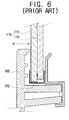
- the screen 110 comprises a lenticular lens sheet 111 in front of a fresnel lens sheet 112.
- the lenticular lens sheet 111 and the fresnel lens sheet 112 are separated by only about 0.1 mm. Consequently, when a user removes dirt from the screen 110 by spraying cleaning liquid in the direction of arrow A in Figure 6, the cleaning liquid may flow down the front face of the screen 110 and then be drawn up between the lens sheets 111, 112 by capillarity. Liquid drawn up between the lens sheets 111, 112 in this way appears as undesirable flecks to the viewer.
- a projection television according to the present invention is characterised by bottom edges of the sheets being received in a channel member which has a drain hole.
- the provision of the drain hole enable liquid, such as cleaning fluid, to drain away, rather than being drawn up between the sheets.
- the bottom edges of the sheets may also be stepped relative to each other as a further measure against liquid being drawn upwards between them by capillarity.
- the drain hole is in the floor of the channel member. However, it could be at the bottom of a side wall.
- the channel member has structures, e.g. steps or shelves, spacing said bottom edges from the floor of the channel member. More preferably, the internal profile of the channel member tapers towards its floor below said bottom edges.
- said sheets comprise a lenticular lens sheet in front of a fresnel lens sheet.
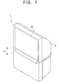
- a projection television comprises a body casing 1, defining the external appearance of the television and comprising a front casing 2 and a rear casing 7, a CRT assembly (not shown) installed inside the body casing 1 for generating a modulated beam, a screen 10 provided in the front casing 2 for displaying a picture formed by the modulated beam from the CRT assembly and a mirror (not shown) for directing the modulated beam onto the screen 10.
- the screen 10 comprises a lenticular lens sheet 11 in front of a fresnel lens sheet 12.
- the lens sheets 11, 12 are separated by a small gap of only about 0.1mm.
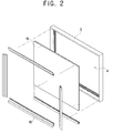
- the front casing 2 comprises a frame 3, having an opening 4 in which the screen 10 is mounted, and a panel 6 below the frame 3 and behind which a plurality of speakers (not shown) are mounted.
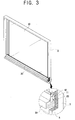
- the frame 3 has an internal, transverse rib 5 which projects backwards below the opening 4 and supports the screen 10 and held in place by a bracket 30 which is attached to the rib 5.
- the bottom edge of the screen 10 is held in a channel member 20 which rests on the rib 5.
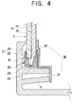
- the channel member 20 has an upper part 21 comprising front and back steps 22, 23 on which respective lens sheets 11, 12 rest when the screen 10 has been pushed into place, and a lower part 24 which tapers internally and has a line of drain holes 25 through its floor.
- the front step 22 is lower than the back step 23 and the lenticular lens sheet 11 projects below the fresnel lens sheet 12.
- Cleaning liquid or water, sprayed onto the screen 10 in the direction of arrow C in Figure 4 flows down the screen and into the channel member 20, from where it can drain through the holes in its floor.
- the lower part 24 is tapered internally, i.e. has sloping sides, so that the moisture permeating through a gap between the frame 3 and the lenticular lens sheet 11, accumulates on the front step 22, flows downward along one of the sloped sides of the lower part 24 and drains away through the drain holes 25.
- the screen supporting bracket 30 is made of a rigid material to support the rear of the screen 10 and is connected to the supporting rib 5.
- the screen supporting bracket 30 comprises a connecting part 31, formed with a shape corresponding to that of the supporting rib 5, for connection to the supporting rib 5 and a contacting part 32, extending upward from the combining part 31 to support the screen 10 and contact the back of the screen 10 or the fresnel lens sheet 12.
- the screen 10 is installed on the supporting rib 5 of the frame 3 so that the screen 10 is exposed to the outside through the opening 4.
- the bottom of the screen 10 is inserted into the upper part 21 of the channel member 20.
- the lenticular lens sheet 11 rests on the front step 22 and the fresnel lens sheet 12 rests on the back step 23.
- the screen supporting bracket 30 is connected to the supporting rib 5.
- the connecting part 31 of the screen supporting bracket 30 is connected to the rib 5
- the contacting part 32 contacts the fresnel lens sheet 12 and supports the screen 10 from the rear.
- At least one drain hole 25 is formed in a channel member 20 supporting the screen 10 to prevent moisture being drawn up between the lens sheets 11, 12 by capillarity as appearing as flecks to viewers.
Landscapes
- Engineering & Computer Science (AREA)
- Multimedia (AREA)
- Signal Processing (AREA)
- Overhead Projectors And Projection Screens (AREA)
- Projection Apparatus (AREA)
- Transforming Electric Information Into Light Information (AREA)
Applications Claiming Priority (2)
| Application Number | Priority Date | Filing Date | Title |
|---|---|---|---|
| KR2003039678 | 2003-06-19 | ||
| KR1020030039678A KR20040110372A (ko) | 2003-06-19 | 2003-06-19 | 프로젝션 텔레비젼 |
Publications (2)
| Publication Number | Publication Date |
|---|---|
| EP1489840A2 true EP1489840A2 (de) | 2004-12-22 |
| EP1489840A3 EP1489840A3 (de) | 2006-03-22 |
Family
ID=33411761
Family Applications (1)
| Application Number | Title | Priority Date | Filing Date |
|---|---|---|---|
| EP04102188A Withdrawn EP1489840A3 (de) | 2003-06-19 | 2004-05-18 | Projektionsfernsehgerät |
Country Status (4)
| Country | Link |
|---|---|
| US (1) | US20040257481A1 (de) |
| EP (1) | EP1489840A3 (de) |
| KR (1) | KR20040110372A (de) |
| CN (1) | CN1287592C (de) |
Families Citing this family (1)
| Publication number | Priority date | Publication date | Assignee | Title |
|---|---|---|---|---|
| FR3115611B1 (fr) * | 2020-10-26 | 2023-03-31 | Valeo Comfort & Driving Assistance | Dispositif d’assemblage adapté pour assembler un écran avec un élément partiellement transparent et afficheur tête haute comprenant un tel dispositif |
Family Cites Families (5)
| Publication number | Priority date | Publication date | Assignee | Title |
|---|---|---|---|---|
| JPH0627921B2 (ja) * | 1987-10-19 | 1994-04-13 | 三菱電機株式会社 | 拡大投写装置 |
| JPH02120977U (de) * | 1989-03-16 | 1990-10-01 | ||
| JP3329147B2 (ja) * | 1995-07-03 | 2002-09-30 | 松下電器産業株式会社 | スクリーン固定装置 |
| JP3163028B2 (ja) * | 1997-02-18 | 2001-05-08 | 三洋電機株式会社 | テレビジョン受信機の水滴逃し構造 |
| KR100465306B1 (ko) * | 2001-12-29 | 2005-01-13 | 엘지전자 주식회사 | 프로젝션 텔레비전의 구조 및 구조의 형성 방법 |
-
2003
- 2003-06-19 KR KR1020030039678A patent/KR20040110372A/ko not_active Ceased
-
2004
- 2004-04-09 US US10/820,749 patent/US20040257481A1/en not_active Abandoned
- 2004-05-18 CN CNB2004100447897A patent/CN1287592C/zh not_active Expired - Fee Related
- 2004-05-18 EP EP04102188A patent/EP1489840A3/de not_active Withdrawn
Non-Patent Citations (1)
| Title |
|---|
| None * |
Also Published As
| Publication number | Publication date |
|---|---|
| KR20040110372A (ko) | 2004-12-31 |
| CN1287592C (zh) | 2006-11-29 |
| CN1574927A (zh) | 2005-02-02 |
| EP1489840A3 (de) | 2006-03-22 |
| US20040257481A1 (en) | 2004-12-23 |
Similar Documents
| Publication | Publication Date | Title |
|---|---|---|
| KR100694932B1 (ko) | 투사형 텔레비전 수신기 및 그의 제조 방법 | |
| US7002640B2 (en) | Apparatus for mounting a screen in a projection television | |
| US12262855B2 (en) | Bathing wall system | |
| EP1489840A2 (de) | Projektionsfernsehgerät | |
| CN210621222U (zh) | 一种洗衣机 | |
| CN210621234U (zh) | 一种洗衣机 | |
| JP3163028B2 (ja) | テレビジョン受信機の水滴逃し構造 | |
| CN210420605U (zh) | 一种洗衣机 | |
| US7403333B2 (en) | Projection television | |
| JP4524853B2 (ja) | スクリーン取り付け装置 | |
| KR20010077550A (ko) | 암실 케이스가 구비된 프로젝션 모니터 | |
| KR100314067B1 (ko) | 프로젝션 텔레비전 | |
| KR0122715Y1 (ko) | 공기조화기의 장식판 결합장치 | |
| JP3094660B2 (ja) | Crt表示装置 | |
| KR20020040307A (ko) | 프로젝션 티브이의 미러 고정 장치 | |
| KR100747832B1 (ko) | 프로젝션 tv의 백커버 결합구조 | |
| JP2009524079A (ja) | 適合性投影テレビジョンスクリーンマウンチングクランプ | |
| JP2004019197A (ja) | 目地材 | |
| JPH05176266A (ja) | 投写型テレビジョン受像機とスクリーン装着方法 | |
| KR20250005761A (ko) | 안정적인 위치고정이 가능한 유리지지구 | |
| KR200317375Y1 (ko) | 멀티스크린용 플라즈마 디스플레이 패널 | |
| JPH1065364A (ja) | 光学フィルタの取付構造 | |
| KR20050106769A (ko) | 스탠드형 피디피 텔레비젼의 화면청소장치 | |
| JP2005304945A (ja) | 収納キャビネット | |
| DE20112055U1 (de) | Gehäuse für ein Rückprojektionsgerät |
Legal Events
| Date | Code | Title | Description |
|---|---|---|---|
| PUAI | Public reference made under article 153(3) epc to a published international application that has entered the european phase |
Free format text: ORIGINAL CODE: 0009012 |
|
| AK | Designated contracting states |
Kind code of ref document: A2 Designated state(s): AT BE BG CH CY CZ DE DK EE ES FI FR GB GR HU IE IT LI LU MC NL PL PT RO SE SI SK TR |
|
| AX | Request for extension of the european patent |
Extension state: AL HR LT LV MK |
|
| PUAL | Search report despatched |
Free format text: ORIGINAL CODE: 0009013 |
|
| AK | Designated contracting states |
Kind code of ref document: A3 Designated state(s): AT BE BG CH CY CZ DE DK EE ES FI FR GB GR HU IE IT LI LU MC NL PL PT RO SE SI SK TR |
|
| AX | Request for extension of the european patent |
Extension state: AL HR LT LV MK |
|
| 17P | Request for examination filed |
Effective date: 20060921 |
|
| 17Q | First examination report despatched |
Effective date: 20061020 |
|
| AKX | Designation fees paid |
Designated state(s): DE GB NL |
|
| GRAP | Despatch of communication of intention to grant a patent |
Free format text: ORIGINAL CODE: EPIDOSNIGR1 |
|
| RIN1 | Information on inventor provided before grant (corrected) |
Inventor name: KIM, SANG-HAK |
|
| STAA | Information on the status of an ep patent application or granted ep patent |
Free format text: STATUS: THE APPLICATION IS DEEMED TO BE WITHDRAWN |
|
| 18D | Application deemed to be withdrawn |
Effective date: 20070908 |