EP1489738B1 - Coefficient estimation method and apparatus - Google Patents
Coefficient estimation method and apparatus Download PDFInfo
- Publication number
- EP1489738B1 EP1489738B1 EP04253183A EP04253183A EP1489738B1 EP 1489738 B1 EP1489738 B1 EP 1489738B1 EP 04253183 A EP04253183 A EP 04253183A EP 04253183 A EP04253183 A EP 04253183A EP 1489738 B1 EP1489738 B1 EP 1489738B1
- Authority
- EP
- European Patent Office
- Prior art keywords
- amplifier
- transmitter
- unit
- predistortion
- signal
- Prior art date
- Legal status (The legal status is an assumption and is not a legal conclusion. Google has not performed a legal analysis and makes no representation as to the accuracy of the status listed.)
- Expired - Lifetime
Links
Images


Classifications
-
- H—ELECTRICITY
- H03—ELECTRONIC CIRCUITRY
- H03F—AMPLIFIERS
- H03F1/00—Details of amplifiers with only discharge tubes, only semiconductor devices or only unspecified devices as amplifying elements
- H03F1/32—Modifications of amplifiers to reduce non-linear distortion
- H03F1/3241—Modifications of amplifiers to reduce non-linear distortion using predistortion circuits
- H03F1/3247—Modifications of amplifiers to reduce non-linear distortion using predistortion circuits using feedback acting on predistortion circuits
-
- H—ELECTRICITY
- H03—ELECTRONIC CIRCUITRY
- H03F—AMPLIFIERS
- H03F2201/00—Indexing scheme relating to details of amplifiers with only discharge tubes, only semiconductor devices or only unspecified devices as amplifying elements covered by H03F1/00
- H03F2201/32—Indexing scheme relating to modifications of amplifiers to reduce non-linear distortion
- H03F2201/3233—Adaptive predistortion using lookup table, e.g. memory, RAM, ROM, LUT, to generate the predistortion
Definitions
- the present invention generally relates to coefficient estimation methods, in particular, coefficient estimation methods used in conjunction with digitally predistorted transmitters and/or amplifiers.
- W-CDMA wideband code division multiple access
- 3G third generation
- BTSs base transceiver stations
- HSDPA high-speed downlink packet access
- RF radio frequency
- the heat produced by the power amplifiers implemented in high-capacity BTSs overwhelms the heat removal capacity of the current BTS infrastructure.
- Increasing the linearity of the power amplifier used in high-capacity BTSs may allow their use in the current BTS infrastructure.
- an amplifier provides uniform gain throughout a dynamic range thereof so that the output signal of the amplifier is a correct, amplified version of an input signal.
- amplifiers exhibit non-ideal properties such as non-linear amplitude and phase distortion, which are undesirable and may deteriorate performance of a system employing the amplifier.
- IMD intermodulation distortion
- RF radio frequency
- a broadband amplifier used in a wireless system may generate various undesirable intermodulation products as a result of amplifying a multitude of channels occurring at fixed frequency intervals across a band.
- the amplifier may be operated in a linear zone. That is, the lower the power level of the amplifier, the smaller the non-linearity manifested by the amplifier. This technique may limit the acceptable operating range of the amplifier, since the amplifier must be operated below maximum power output to avoid undesirable non-linearity.
- Another possible linearization method includes using a testing stage applied to an amplifier prior to a field implementation thereof.
- a test signal may be slowly amplified, corresponding output signals may be sampled over a period, and the input signals may be compared with the sampled output signals so as to determine distortion parameters specific to the amplifier at the time the sampling was performed.
- These distortion parameters also known as coefficients, may be used to modify an input signal of the amplifier such that an output therefrom is as linear as possible.
- This technique for compensating for the non-linearity of an amplifier requires a significant period of time to complete. Moreover, the determined distortion parameters may not be optimum for various amplifier input signals.
- At least one signal burst is applied to a transmitter including an amplifier to train or adjust a predistortion circuit associated with the amplifier.
- Predistortion coefficients generated as a result of the training may be used by the transmitter to predistort call traffic processed thereby.
- a unit applies at least one training signal burst to a transmitter including an amplifier to train or adjust a predistortion circuit associated with the amplifier. Similar to the first embodiment, predistortion coefficients generated as a result of the training may be used by the transmitter to predistort call traffic in a wireless communications system.
- a first training signal burst is applied, a first set of coefficients based upon the first training signal burst is calculated, a second training signal burst is applied, the second training signal burst is predistorted using the first set of coefficients, and a second set of coefficients is calculated based upon the predistorted second training signal burst.
- a transmitter according to an exemplary embodiment of the present invention will be described.
- a pulse generation unit according to an exemplary embodiment of the present invention will be described.
- a coefficient estimation method according to an exemplary embodiment of the present invention will be described.
- alternative exemplary embodiments of the present invention will be described.
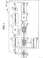
- FIG. 1 illustrates a transmitter 100 having a pulse generation unit 102 interfaced (described later) thereto for implementing a coefficient estimation method in accordance with an exemplary embodiment of the present invention.
- the transmitter 100 may be implemented in various devices that transmit signals.
- the transmitter 100 may be used in a base transceiver station (BTS), a transceiver, etc.
- BTS base transceiver station
- the transmitter 100 includes a predistortion unit 110, a digital to analog converter 112, a first mixers and filters unit 114, an amplifier 116, a second mixers and filters unit 118, an analog to digital converter 120, an amplifier characteristics estimation unit 122, a calculate predistortion function unit 124 and a lookup table unit 126.
- a source signal u(n) is input to the transmitter 100 and processed by the predistortion unit 110.
- the source signal u(n) may or may not undergo predistortion by the predistortion unit 110. That is, the predistortion unit 110 may pass the source signal u(n) unchanged to the amplifier 116 for amplification and output by the transmitter 100. However, the predistortion unit 110 may also predistort the source signal u(n) in the predistortion unit 110.
- the source signal u(n) will undergo predistortion by the predistortion unit 110.
- the predistortion unit 110 outputs a signal x(n), which is converted to an analog signal by the digital to analog converter 112.
- the converted signal is up-converted to radio frequency (RF) by the first mixers and filters unit 114.
- the RF signal is received by the amplifier 116, amplified, output as an output signal z(n) and transmitted by an antenna 128.
- the output signal z(n) from the amplifier 116 may also be sampled and fed back to the amplifier characteristics estimation unit 122.
- the signal output by the amplifier 116 is processed by the second mixers and filters unit 118.
- the second mixers and filters unit 118 down-converts the output signal z(n) to a signal in the intermediate frequency (IF) range.
- the IF signal is converted by the analog to digital converter 120 to a signal y(n) that can be processed by the amplifier characteristics unit 122.
- the amplifier characteristics estimation unit 122 which uses a known process, compares the signal x(n) output from the predistortion unit 110 with the analog signal y(n) received from the analog to digital converter 120.
- the output of the amplifier characteristics estimation unit 122 is a complex polynomial equation that models the baseband behavior of the amplifier 116.
- the complex polynomial output by the unit 122 is used by the calculate predistortion function unit 124 in a known manner to provide an approximate function providing a coefficient vector that makes the relationship between signals u(n) and z(n) as linear as possible.
- the approximate function would be an inverse function of the complex polynomial equation output from the amplifier characteristics estimation unit 122.
- Coefficients of the coefficient vector may be stored in the form of a lookup table in the lookup table unit 126.
- the use of the lookup table unit 126 saves calculation load that would be required if coefficients had to be calculated on the fly.
- the calculate predistortion unit 124 may be interfaced directly with the predistortion unit 110, so that calculated coefficients can pass directly from the calculate predistortion function unit 124 to the predistortion unit 110. Nonetheless, the predistortion unit 110 uses the coefficients to predistort the input signal u(n) with the goal of providing the output signal z(n) with near linear relationship to the input signal u(n).
- FIG. 1 illustrates a pulse generator 102 that is interfaced the transmitter 100.
- the pulse generator 102 is capable of generating pulses of white Gaussian noise; uniform white noise, Poisson noise, or the like, that may be received and processed by the transmitter 100. These pulses generally have a particular power level, and in particular, the pulses generally have a power level capable of exciting or nearly exciting a full dynamic range of the amplifier 116.
- the pulse generator 102 is used to train the transmitter 100 before actual traffic signals are processed thereby.
- the coefficients used by the predistortion unit 110 and stored in the lookup table 126 should be developed.
- the pulses generated by the pulse generator 102 are used by the amplifier characteristics estimation unit 122 and the calculate predistortion function unit 124 for this purpose.
- At least one or more pulses generated by the pulse generator 102 may be applied to the transmitter 100 with the sole purpose of exciting the amplifier 116 to an upper level of its full dynamic range. This is desirable, since the amplifier 116 may not reach the upper level of its full dynamic range during normal operation, where traffic signals are being processed.
- These pulses are also processed by the amplifier characteristics estimation unit 122 and the calculate predistortion function unit 124 in a known manner to develop a set of predistortion coefficients that may be stored in the lookup table unit 126 and used by the predistortion unit 110 to predistort regular traffic signals processed by the transmitter 100.
- the pulse generation unit 102 generates at least one pulse that is added to a traffic signal in order to excite or nearly excite the full dynamic range of the amplifier 116.
- the pulse generation unit 102 may generate two pulses that are used to train the transmitter 100 before actual traffic signals are processed by the transmitter 100, and subsequently, an additional pulse may be generated by the pulse generation unit 102 that is added to a traffic signal as it is processed by the transmitter 100.
- coefficients are first generated in the absence of traffic signals, and then coefficients are generated while a traffic signal is being processed.
- the pulse generation unit 102 should take into consideration the current power level of the traffic signal in adding the pulse to a traffic signal. That is, the added pulse should be inversely proportional to the current power level of the traffic signal it is applied to.
- FIG. 2 is a graph 200 illustrating a plurality of pulses 302 used to train the transmitter 100.
- FIG. 3 is a graph 300 illustrating a plurality of pulses 302, where one pulse 302 is added to a traffic signal 304, in accordance with an exemplary embodiment of the present invention.
- the vertical axes of FIGS. 2 and 3 represent the dynamic range of amplifier 116 and the horizontal axes represent time.
- the plurality of pulses 302 are applied to the transmitter 100 from the pulse generator 102 before the traffic signal 304 is present.
- FIG. 3 illustrates two pulses 302 that are applied to the transmitter 100 before the traffic signal 304 is present, and one pulse 302 is applied to the transmitter 100 when the traffic signal 304 is already present.
- the pulse 302 is applied on top of the traffic signal 302, while taking into consideration the power level of the traffic signal 304 in order to avoid exceeding a maximum dynamic range of the amplifier 116.
- the coefficient estimating method relates to training transmitters employing predistortion systems, before the transmitters are placed in operational service. However, it should be understood that according to an embodiment of the invention the described coefficient estimating method also apply to transmitters actively processing traffic signals.
- the exemplary embodiment will be discussed in conjunction with the transmitter illustrated in FIG. 1 , but this is done by way of illustration only.
- the method of estimating coefficients according to an exemplary embodiment of the present invention may be implemented in other arrangements similar to the transmitter illustrated in FIG. 1 .
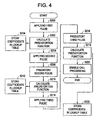
- a first pulse having a first amplitude is applied to the transmitter 100 (S200).
- the first pulse (signal) passes through the predistortion unit 110 without undergoing predistortion. This is because the lookup table unit 126 does not currently have predistortion coefficients stored therein.
- the amplifier characteristics estimation unit 122 calculates a complex polynomial equation and passes the equation to the calculate predistortion function unit 124 (S202).
- the calculate predistortion function unit 124 provides a coefficient vector of coefficients, based upon the complex polynomial equation, that may be stored in the lookup table 126 (S204). These coefficients may be used directly by the predistortion unit 110 to predistort signals input to the transmitter 100.
- a second pulse having a second amplitude is applied to the transmitter 100 (S206).
- the second pulse (signal) passes through the predistortion unit 110 and is predistorted with coefficients stored in the lookup table 126 (S208).
- the coefficients used are those calculated as a result of the first pulse.
- the amplifier characteristics estimation unit 122 After the second pulse undergoes processing, as described hereinabove, it is received by the amplifier characteristics estimation unit 122 as the signal y(n).
- the amplifier characteristics estimation unit 122 calculates a complex polynomial equation and passes the equation to the calculate predistortion function unit 124 (S210).
- the calculate predistortion function unit 124 provides a coefficient vector of coefficients, based upon the complex polynomial equation, that may be stored in the lookup table 126 (S212). These coefficients may also be used directly by the predistortion unit 110 to predistort signals input to the transmitter 100.
- a third pulse having a third amplitude is applied to the transmitter 100 (S214).
- the third pulse (signal) passes through the predistortion unit 110 and is predistorted with coefficients stored in the lookup table 126 (S216).
- the coefficients used are those calculated as a result of the second pulse.
- the amplifier characteristics estimation unit 122 After the third pulse undergoes processing, as described hereinabove, it is received by the amplifier characteristics estimation unit 122 as the signal y(n).
- the amplifier characteristics estimation unit 122 calculates a complex polynomial equation and passes the equation to the calculate predistortion function unit 124 (S218).
- the calculate predistortion function unit 124 provides a coefficient vector of coefficients, based upon the complex polynomial equation, that may be stored in the lookup table 126 (S220). These coefficients may also be used directly by the predistortion unit 110 to predistort signals input to the transmitter 100.
- the transmitter may be enabled for call processing (S222). That is, call traffic may be processed and effectively predistorted using coefficients stored in the lookup table 126.
- the processing of the three pulses in accordance with an exemplary embodiment of the present invention provides a set of coefficients that may be used by the transmitter 100 to predistort incoming call traffic
- the set of coefficients may be modified and/or supplanted due to any changes that may occur in the operational characteristics of the transmitter 100.
- the operational characteristics of the amplifier 116 may change as it ages.
- the amplifier 116 may be operated at different temperatures and power levels over time.
- coefficients stored in the lookup table 126 may be modified via the amplifier characteristics estimation unit 122 and the calculate predistortion function unit 124, so that a change in a characteristic associated with the amplifier 116 is taken into consideration.
- the exemplary embodiments of the present invention are not limited to the use of only three pulses to train a predistortion arrangement of a transmitter.
- a greater number of pulses may be used to provide predistortion coefficients that may offer superior linearity.
- less than three pulses may be used if transmitter linearity is of less importance.
- the exemplary embodiments of the present invention are described implementing three pulses having a first, second and third amplitude level, respectively. These amplitude levels may be equal to each other, or may differ. For example, the first amplitude level may be less than the second amplitude level, and the second amplitude level may be less than the third amplitude level. Similarly, the third amplitude level may be less than the second amplitude level, and the second amplitude level may be less than the first amplitude level.
Landscapes
- Physics & Mathematics (AREA)
- Nonlinear Science (AREA)
- Engineering & Computer Science (AREA)
- Power Engineering (AREA)
- Amplifiers (AREA)
- Digital Transmission Methods That Use Modulated Carrier Waves (AREA)
- Transmitters (AREA)
Applications Claiming Priority (2)
| Application Number | Priority Date | Filing Date | Title |
|---|---|---|---|
| US10/460,380 US7720171B2 (en) | 2003-06-13 | 2003-06-13 | Coefficient estimation method and apparatus |
| US460380 | 2003-06-13 |
Publications (2)
| Publication Number | Publication Date |
|---|---|
| EP1489738A1 EP1489738A1 (en) | 2004-12-22 |
| EP1489738B1 true EP1489738B1 (en) | 2009-07-01 |
Family
ID=33418098
Family Applications (1)
| Application Number | Title | Priority Date | Filing Date |
|---|---|---|---|
| EP04253183A Expired - Lifetime EP1489738B1 (en) | 2003-06-13 | 2004-05-28 | Coefficient estimation method and apparatus |
Country Status (4)
| Country | Link |
|---|---|
| US (1) | US7720171B2 (enExample) |
| EP (1) | EP1489738B1 (enExample) |
| JP (1) | JP4791707B2 (enExample) |
| DE (1) | DE602004021749D1 (enExample) |
Families Citing this family (7)
| Publication number | Priority date | Publication date | Assignee | Title |
|---|---|---|---|---|
| US7653147B2 (en) * | 2005-08-17 | 2010-01-26 | Intel Corporation | Transmitter control |
| KR100646855B1 (ko) * | 2005-10-07 | 2006-11-23 | 한국전자통신연구원 | 고전력 증폭기의 특성 모델링을 이용한 비선형 왜곡 보상장치 및 그 방법 |
| TWI363487B (en) * | 2008-10-20 | 2012-05-01 | Ralink Technology Corp | Lookup table generation method and related device for a predistorter |
| CN102082752B (zh) * | 2010-02-25 | 2014-03-19 | 电信科学技术研究院 | 一种数字预失真处理方法及设备 |
| US8787494B2 (en) * | 2012-06-11 | 2014-07-22 | Telefonaktiebolaget L M Ericsson (Publ) | Modeling digital predistorter |
| JP6035919B2 (ja) * | 2012-07-09 | 2016-11-30 | 富士通株式会社 | 送信装置、及び送信方法 |
| JP6255917B2 (ja) * | 2013-11-07 | 2018-01-10 | 富士通株式会社 | 無線装置及び無線アクセスシステム |
Family Cites Families (35)
| Publication number | Priority date | Publication date | Assignee | Title |
|---|---|---|---|---|
| GB2265269B (en) * | 1992-03-02 | 1995-08-30 | Motorola Ltd | Radio transmitter with linearization training sequence |
| GB2272133B (en) * | 1992-11-02 | 1996-06-12 | Motorola Inc | Radio system |
| EP0665996A1 (en) * | 1993-08-20 | 1995-08-09 | Motorola, Inc. | Radio transmitter with power amplifier linearizer |
| JP3300185B2 (ja) * | 1995-01-31 | 2002-07-08 | 株式会社日立国際電気 | 無線機および無線機の使用方法 |
| US5748678A (en) * | 1995-07-13 | 1998-05-05 | Motorola, Inc. | Radio communications apparatus |
| JP3537228B2 (ja) * | 1995-08-18 | 2004-06-14 | 富士通株式会社 | 無線通信用基地局 |
| US5870668A (en) * | 1995-08-18 | 1999-02-09 | Fujitsu Limited | Amplifier having distortion compensation and base station for radio communication using the same |
| US5892397A (en) * | 1996-03-29 | 1999-04-06 | Spectrian | Adaptive compensation of RF amplifier distortion by injecting predistortion signal derived from respectively different functions of input signal amplitude |
| JPH10132883A (ja) * | 1996-11-01 | 1998-05-22 | Shimada Phys & Chem Ind Co Ltd | 増幅器の特性監視方法及び監視制御装置 |
| US5923712A (en) * | 1997-05-05 | 1999-07-13 | Glenayre Electronics, Inc. | Method and apparatus for linear transmission by direct inverse modeling |
| US5867065A (en) * | 1997-05-07 | 1999-02-02 | Glenayre Electronics, Inc. | Frequency selective predistortion in a linear transmitter |
| US6054894A (en) * | 1998-06-19 | 2000-04-25 | Datum Telegraphic Inc. | Digital control of a linc linear power amplifier |
| US6054896A (en) * | 1998-12-17 | 2000-04-25 | Datum Telegraphic Inc. | Controller and associated methods for a linc linear power amplifier |
| US6600792B2 (en) * | 1998-06-26 | 2003-07-29 | Qualcomm Incorporated | Predistortion technique for high power amplifiers |
| US6272336B1 (en) * | 1998-12-30 | 2001-08-07 | Samsung Electronics Co., Ltd. | Traffic-weighted closed loop power detection system for use with an RF power amplifier and method of operation |
| WO2000074232A1 (en) * | 1999-05-28 | 2000-12-07 | Fujitsu Limited | Predistortion type distortion compensation amplifier |
| US6587514B1 (en) * | 1999-07-13 | 2003-07-01 | Pmc-Sierra, Inc. | Digital predistortion methods for wideband amplifiers |
| US6246286B1 (en) * | 1999-10-26 | 2001-06-12 | Telefonaktiebolaget Lm Ericsson | Adaptive linearization of power amplifiers |
| US6751447B1 (en) * | 1999-12-30 | 2004-06-15 | Samsung Electronics Cop., Ltd. | Adaptive digital pre-distortion circuit using output reference signal and method of operation |
| JP2002064411A (ja) * | 2000-08-16 | 2002-02-28 | Matsushita Electric Ind Co Ltd | ディジタル送信装置 |
| SE517456C2 (sv) * | 2000-09-07 | 2002-06-11 | Ericsson Telefon Ab L M | MCPA-kalibrering off-line |
| US6545535B2 (en) * | 2000-10-12 | 2003-04-08 | Telefonaktiebolaget Lm Ericsson (Publ) | Method and apparatus for reducing distortion |
| KR20020054149A (ko) * | 2000-12-27 | 2002-07-06 | 엘지전자 주식회사 | 디지털 전치왜곡기를 갖는 기지국 송신장치 |
| US6496062B1 (en) * | 2001-07-13 | 2002-12-17 | Lucent Technologies Inc. | Predistortion system and method using a pilot signal |
| KR100408043B1 (ko) * | 2001-09-21 | 2003-12-01 | 엘지전자 주식회사 | 디지탈 아이에프 기술을 적용한 전치 왜곡 방식의 디지털선형화기 |
| US20030058959A1 (en) * | 2001-09-25 | 2003-03-27 | Caly Networks. | Combined digital adaptive pre-distorter and pre-equalizer system for modems in link hopping radio networks |
| JP4654555B2 (ja) * | 2001-09-27 | 2011-03-23 | 日本電気株式会社 | 送信電力制御システムおよび送信電力調整方法 |
| US7058369B1 (en) * | 2001-11-21 | 2006-06-06 | Pmc-Sierra Inc. | Constant gain digital predistortion controller for linearization of non-linear amplifiers |
| US7085330B1 (en) * | 2002-02-15 | 2006-08-01 | Marvell International Ltd. | Method and apparatus for amplifier linearization using adaptive predistortion |
| US7313199B2 (en) * | 2002-03-21 | 2007-12-25 | Hypres, Inc. | Power amplifier linearization |
| US6775330B2 (en) * | 2002-04-29 | 2004-08-10 | The Boeing Company | Predistorted modulation system for bandwidth efficient satellite links |
| US6879641B2 (en) * | 2002-06-13 | 2005-04-12 | Bigband Networks Bas, Inc. | Transmit pre-equalization in a modem environment |
| US6642786B1 (en) * | 2002-08-15 | 2003-11-04 | Electronics And Telecommunications Research Institute | Piecewise polynomial predistortion method and apparatus for compensating nonlinear distortion of high power amplifier |
| US20040142667A1 (en) * | 2003-01-21 | 2004-07-22 | Lochhead Donald Laird | Method of correcting distortion in a power amplifier |
| US6985033B1 (en) * | 2003-05-15 | 2006-01-10 | Marvell International Ltd. | Circuits and methods for adjusting power amplifier predistortion, and power amplifiers and other devices including the same |
-
2003
- 2003-06-13 US US10/460,380 patent/US7720171B2/en active Active
-
2004
- 2004-05-28 EP EP04253183A patent/EP1489738B1/en not_active Expired - Lifetime
- 2004-05-28 DE DE602004021749T patent/DE602004021749D1/de not_active Expired - Lifetime
- 2004-06-11 JP JP2004173271A patent/JP4791707B2/ja not_active Expired - Fee Related
Also Published As
| Publication number | Publication date |
|---|---|
| US20040252784A1 (en) | 2004-12-16 |
| JP2005006326A (ja) | 2005-01-06 |
| DE602004021749D1 (de) | 2009-08-13 |
| JP4791707B2 (ja) | 2011-10-12 |
| EP1489738A1 (en) | 2004-12-22 |
| US7720171B2 (en) | 2010-05-18 |
Similar Documents
| Publication | Publication Date | Title |
|---|---|---|
| KR100958046B1 (ko) | 전송기 성능을 개선시키기 위해 기저 대역 변환을사용하는 방법 및 장치 | |
| US6794936B2 (en) | Equalizer system and method for predistortion | |
| US6903604B2 (en) | Method and apparatus for modeling and estimating the characteristics of a power amplifier | |
| US9432228B2 (en) | Digital pre-distortion filter system and method | |
| US8982995B1 (en) | Communication device and method of multipath compensation for digital predistortion linearization | |
| US6677870B2 (en) | Device and method for compensating for nonlinearity of power amplifier with predistortion in IF band | |
| EP2795792B1 (en) | Adaptive predistortion for a non-linear subsystem based on a model as a concatenation of a non-linear model followed by a linear model | |
| JP4087180B2 (ja) | 入力信号に予め歪みを加える方法および予歪みシステム | |
| CN107276546B (zh) | 一种数字预失真处理方法及装置 | |
| US20110235748A1 (en) | Active antenna array having analogue transmitter linearisation and a method for predistortion of radio signals | |
| US20160065249A1 (en) | Capture selection for digital pre-distortion adaptation and capture concatenation for frequency hopping pre-distortion adaptation | |
| Tripathi et al. | Swish activation based deep neural network predistorter for RF-PA | |
| US6498529B1 (en) | Method and apparatus for calculating the predistortion function from a power amplifier | |
| EP1489738B1 (en) | Coefficient estimation method and apparatus | |
| US7030693B2 (en) | Enhanced predistortion method and apparatus | |
| JP4619827B2 (ja) | 歪補償装置 | |
| EP2795802B1 (en) | Architecture of a low bandwidth predistortion system for non-linear rf components | |
| US7816984B2 (en) | Lookup table generation method and related device for a predistorter | |
| US8396149B1 (en) | Adaptive signal decompression | |
| EP2161841B1 (en) | Predistortion of a radio frequency signal | |
| Liu et al. | Pre-compensation for the dynamic nonlinearity of wideband wireless transmitters using augmented Wiener predistorters | |
| KR101712752B1 (ko) | 전치왜곡 아날로그 빔 포밍 시스템 및 전치왜곡 방법 | |
| JP2003174370A (ja) | 非線形補償回路と基地局装置および送信電力クリップ方法 | |
| KR101683457B1 (ko) | 포화 영역을 고려하는 디지털 전치왜곡 전력 증폭 장치 및 방법 | |
| KR20100045630A (ko) | 전력 증폭 장치 및 방법 |
Legal Events
| Date | Code | Title | Description |
|---|---|---|---|
| PUAI | Public reference made under article 153(3) epc to a published international application that has entered the european phase |
Free format text: ORIGINAL CODE: 0009012 |
|
| 17P | Request for examination filed |
Effective date: 20040614 |
|
| AK | Designated contracting states |
Kind code of ref document: A1 Designated state(s): AT BE BG CH CY CZ DE DK EE ES FI FR GB GR HU IE IT LI LU MC NL PL PT RO SE SI SK TR |
|
| AX | Request for extension of the european patent |
Extension state: AL HR LT LV MK |
|
| AKX | Designation fees paid |
Designated state(s): DE FR GB |
|
| 17Q | First examination report despatched |
Effective date: 20060509 |
|
| 17Q | First examination report despatched |
Effective date: 20060509 |
|
| GRAP | Despatch of communication of intention to grant a patent |
Free format text: ORIGINAL CODE: EPIDOSNIGR1 |
|
| GRAS | Grant fee paid |
Free format text: ORIGINAL CODE: EPIDOSNIGR3 |
|
| GRAA | (expected) grant |
Free format text: ORIGINAL CODE: 0009210 |
|
| AK | Designated contracting states |
Kind code of ref document: B1 Designated state(s): DE FR GB |
|
| REG | Reference to a national code |
Ref country code: GB Ref legal event code: FG4D |
|
| REF | Corresponds to: |
Ref document number: 602004021749 Country of ref document: DE Date of ref document: 20090813 Kind code of ref document: P |
|
| RAP4 | Party data changed (patent owner data changed or rights of a patent transferred) |
Owner name: LUCENT TECHNOLOGIES INC. |
|
| PLBE | No opposition filed within time limit |
Free format text: ORIGINAL CODE: 0009261 |
|
| STAA | Information on the status of an ep patent application or granted ep patent |
Free format text: STATUS: NO OPPOSITION FILED WITHIN TIME LIMIT |
|
| 26N | No opposition filed |
Effective date: 20100406 |
|
| REG | Reference to a national code |
Ref country code: GB Ref legal event code: 732E Free format text: REGISTERED BETWEEN 20131107 AND 20131113 |
|
| REG | Reference to a national code |
Ref country code: FR Ref legal event code: CD Owner name: ALCATEL-LUCENT USA INC. Effective date: 20131122 |
|
| REG | Reference to a national code |
Ref country code: FR Ref legal event code: GC Effective date: 20140410 |
|
| REG | Reference to a national code |
Ref country code: FR Ref legal event code: RG Effective date: 20141015 |
|
| REG | Reference to a national code |
Ref country code: FR Ref legal event code: PLFP Year of fee payment: 12 |
|
| REG | Reference to a national code |
Ref country code: FR Ref legal event code: PLFP Year of fee payment: 13 |
|
| REG | Reference to a national code |
Ref country code: FR Ref legal event code: PLFP Year of fee payment: 14 |
|
| REG | Reference to a national code |
Ref country code: FR Ref legal event code: PLFP Year of fee payment: 15 |
|
| PGFP | Annual fee paid to national office [announced via postgrant information from national office to epo] |
Ref country code: GB Payment date: 20180518 Year of fee payment: 15 |
|
| PGFP | Annual fee paid to national office [announced via postgrant information from national office to epo] |
Ref country code: DE Payment date: 20190514 Year of fee payment: 16 |
|
| PGFP | Annual fee paid to national office [announced via postgrant information from national office to epo] |
Ref country code: FR Payment date: 20190410 Year of fee payment: 16 |
|
| GBPC | Gb: european patent ceased through non-payment of renewal fee |
Effective date: 20190528 |
|
| PG25 | Lapsed in a contracting state [announced via postgrant information from national office to epo] |
Ref country code: GB Free format text: LAPSE BECAUSE OF NON-PAYMENT OF DUE FEES Effective date: 20190528 |
|
| REG | Reference to a national code |
Ref country code: DE Ref legal event code: R119 Ref document number: 602004021749 Country of ref document: DE |
|
| PG25 | Lapsed in a contracting state [announced via postgrant information from national office to epo] |
Ref country code: FR Free format text: LAPSE BECAUSE OF NON-PAYMENT OF DUE FEES Effective date: 20200531 |
|
| PG25 | Lapsed in a contracting state [announced via postgrant information from national office to epo] |
Ref country code: DE Free format text: LAPSE BECAUSE OF NON-PAYMENT OF DUE FEES Effective date: 20201201 |