EP1489593A2 - Unterwasserschallquelle mit piezoelektrischen oder magnetostriktiven Stäben - Google Patents
Unterwasserschallquelle mit piezoelektrischen oder magnetostriktiven Stäben Download PDFInfo
- Publication number
- EP1489593A2 EP1489593A2 EP04102658A EP04102658A EP1489593A2 EP 1489593 A2 EP1489593 A2 EP 1489593A2 EP 04102658 A EP04102658 A EP 04102658A EP 04102658 A EP04102658 A EP 04102658A EP 1489593 A2 EP1489593 A2 EP 1489593A2
- Authority
- EP
- European Patent Office
- Prior art keywords
- spring element
- sound source
- sides
- actuator
- actuator element
- Prior art date
- Legal status (The legal status is an assumption and is not a legal conclusion. Google has not performed a legal analysis and makes no representation as to the accuracy of the status listed.)
- Withdrawn
Links
Images
Classifications
-
- G—PHYSICS
- G10—MUSICAL INSTRUMENTS; ACOUSTICS
- G10K—SOUND-PRODUCING DEVICES; METHODS OR DEVICES FOR PROTECTING AGAINST, OR FOR DAMPING, NOISE OR OTHER ACOUSTIC WAVES IN GENERAL; ACOUSTICS NOT OTHERWISE PROVIDED FOR
- G10K9/00—Devices in which sound is produced by vibrating a diaphragm or analogous element, e.g. fog horns, vehicle hooters or buzzers
- G10K9/12—Devices in which sound is produced by vibrating a diaphragm or analogous element, e.g. fog horns, vehicle hooters or buzzers electrically operated
- G10K9/121—Flextensional transducers
Definitions
- the invention relates to an underwater sound source comprising an actuator element that vibrates in a reciprocating manner, whereby the distance between the ends of the actuator element varies, and a spring element that is secured to the ends of the actuator element, whereby the spring element moves by the action of the actuator element.
- a structure which comprises an actuator, such as a piezoceramic actuator or a magnetostrictive actuator, that vibrates in a reciprocating manner, whereby the distance between the actuator ends varies.
- an actuator such as a piezoceramic actuator or a magnetostrictive actuator
- the spring element is typically elliptic in shape as set forth in US Patent 5,497,357.
- EP publication 0 475 343 discloses a sound source which also comprises an actuator that vibrates in a reciprocating manner and a spring element attached to the ends thereof.
- the sides of the spring element are concave, i.e. they curve inwardly. This solution poses problems similar to those in the elliptic structure.
- the object of the present invention is to provide a novel underwater sound source.
- the method of the invention is characterized in that in lateral view the spring element is substantially rectangular, that ends of the spring element are elastic, that sides of the spring element are elastic and that the ends and the sides are joined together by substantially rigid corners.
- a sound source comprises an actuator that vibrates in a reciprocating manner such that the distance between the actuator element ends varies.
- a spring element which moves by the action of the actuator element.
- the spring element is substantially rectangular.
- the ends of spring element rectangle are elastic and so are the sides of the rectangle.
- the ends and the sides of the rectangle are joined together by substantially rigid corners.
- This structure provides a considerable reduction in the effect of the resonance frequency of the sound source and the anti-resonance after the resonance on the motion of the actuator element.
- the basic idea of one embodiment is that the spring element is arranged to vibrate such that the shape of the spring element sides varies between concave and convex.
- the structure of the spring element is simple and relatively easy to manufacture.
- the rectangular shape of the spring element is also advantageous for the placement of an actuator element that is rectangular in lateral view.
- the wall structure of the spring element may be of uniform thickness, or in accordance with one embodiment, the structure of the spring element wall is provided with areas that bend more easily. The areas that bend more easily can be provided by thinning the walls, for instance. The areas that bend more easily can be provided in the ends or sides, or both, of the spring element.
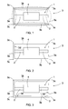
- Figure 1 shows an underwater sound source comprising an actuator element 1.
- the actuator element 1 can be a piezoceramic or magnetostrictive actuator, for instance.
- the actuator element 1 may consist of rods 2, such as magnetostrictive rods or piezoelectric rods, which are made of a suitable material.
- the rod 2 can be divided into a plurality of shorter parts and there may be a plurality of rods in parallel.
- the actuator element 1 comprises means for controlling an electric or magnetic field to affect the rod 2 such that the rod becomes shorter or longer in the longitudinal direction, i.e. the distance between the ends of the actuator element 1 varies, in other words the actuator element 1 oscillates.
- the means for controlling the actuator element 1 are known per se to the person skilled in the art, and thus, for the sake of clarity, they are not shown in the attached drawing.
- a spring element 3 having an orthogonal, i.e. rectangular shape in lateral view.
- the rods of the actuator element 1 are attached at their ends to the spring element ends 3a.
- the spring element ends 3a are joined to the spring element sides 3b by substantially rigid corners 3c.
- the spring element ends 3a are elastic and so are the spring element sides 3b.
- the elasticity of the ends 3a and the sides 3b and the rigidity of the corners 3c effect that as the actuator element 1 gets longer, the spring element 3 takes the shape as indicated by a broken line in Figure 3.
- the spring element ends 3a curve outwardly and the spring element sides 3b curve inwardly.
- the ends 3a and the sides 3b take the shape as indicated by a dash-and-dot line in Figure 1.
- the spring element ends 3a curve inwardly and the spring element sides 3b curve outwardly.
- the operating principle is typical only at a first resonance frequency and therebelow. At frequencies higher than that the behaviour changes: the phase shift between the sides becomes indeterminate and free vibration of a higher order is produced in the sides.
- the material and the dimensions of the spring element 3 determine resonance frequencies and a useable frequency range for a transmitter.
- the spring element wall must be sufficiently thick in order that the first resonance of the spring element 3 would be clean and it would be close to the lower limit frequency of the sound source.
- the spring element 3 can be made of metal, for instance, but most advantageously the spring element 3 is made of a plastic composite, such as carbon fibre or glass fibre, whereby the resonances will be lower due to high loss modulus of the material.
- the length of the longer side, i.e. side 3b, of the spring element may be within the range of 4 to 150 cm, for instance.
- the ratio of the shorter side, i.e. side 3a, to the longer side is advantageously about 1 to 2.
- the ratio of the thickness of the wall to the longer side in the spring element 3 may be between 1 to 30 and 1 to 50, for instance, depending on the elastic modulus of the material.
- the ratio of the width to the longer side in the spring element 3 is most advantageously between 1 to 2 and 1 to 1.
- the rods 2 of the actuator element are attached to a support element 4, which in turn is secured in a fixed manner to the body of a sound transmitter.
- a support element 4 which in turn is secured in a fixed manner to the body of a sound transmitter.
- the body of the sound transmitter is not shown in the attached drawings.
- the sound source operates its shape changes from a rectangle to shapes in accordance with those denoted by a broken line and a dash-and-dot line and the shapes between those two.
- the ends 3a and the sides 3b are surfaces that vibrate differently and that are separated by the corners 3c to form separate wholes.
- Figure 2 shows a sound source, in which the ends 3a of the spring element 3 are provided with areas which bend more easily than others.
- the easily bending areas are provided by making recesses 3d in the spring element wall.
- the easily bending areas are so-called hinge points, by which the elasticity of the ends 3a can be improved.
- easily bending areas are also formed in the sides 3b of the spring element. Also in this case the easily bending areas are provided by making recesses 3d in the spring element wall. Naturally, the easily bending areas can also be provided by modifying the properties of the material, for instance, without changing the thickness thereof.
- the spring element vibrates, for instance for the sides 3b, to achieve both a convex and a concave shape, i.e. on both sides of the rectangular shape.
- the vibration will be relatively symmetrical.
- the spring element 1 will not necessarily vibrate in such a manner that the sides 3 would curve outwardly.
- the sound source may be provided with a casing and its structure may be reinforced in a desired manner.
Landscapes
- Physics & Mathematics (AREA)
- Engineering & Computer Science (AREA)
- Acoustics & Sound (AREA)
- Multimedia (AREA)
- Apparatuses For Generation Of Mechanical Vibrations (AREA)
- General Electrical Machinery Utilizing Piezoelectricity, Electrostriction Or Magnetostriction (AREA)
- Piezo-Electric Transducers For Audible Bands (AREA)
Applications Claiming Priority (2)
| Application Number | Priority Date | Filing Date | Title |
|---|---|---|---|
| FI20030918A FI119455B (fi) | 2003-06-18 | 2003-06-18 | Vedenalainen äänilähde |
| FI20030918 | 2003-06-18 |
Publications (2)
| Publication Number | Publication Date |
|---|---|
| EP1489593A2 true EP1489593A2 (de) | 2004-12-22 |
| EP1489593A3 EP1489593A3 (de) | 2008-07-02 |
Family
ID=8566275
Family Applications (1)
| Application Number | Title | Priority Date | Filing Date |
|---|---|---|---|
| EP04102658A Withdrawn EP1489593A3 (de) | 2003-06-18 | 2004-06-11 | Unterwasserschallquelle mit piezoelektrischen oder magnetostriktiven Stäben |
Country Status (4)
| Country | Link |
|---|---|
| US (1) | US20050008174A1 (de) |
| EP (1) | EP1489593A3 (de) |
| FI (1) | FI119455B (de) |
| NO (1) | NO20042517L (de) |
Families Citing this family (1)
| Publication number | Priority date | Publication date | Assignee | Title |
|---|---|---|---|---|
| FI121764B (fi) * | 2008-12-31 | 2011-03-31 | Patria Aviat Oy | Nesteessä oleva värähtelijä |
Family Cites Families (7)
| Publication number | Priority date | Publication date | Assignee | Title |
|---|---|---|---|---|
| WO1987005772A1 (en) * | 1986-03-19 | 1987-09-24 | The Secretary Of State For Defence In Her Britanni | Sonar transducers |
| US4864548A (en) * | 1986-06-13 | 1989-09-05 | Image Acoustics, Inc. | Flextensional transducer |
| CA1333419C (en) * | 1988-01-18 | 1994-12-06 | Douglas Brian Arnold | Flextensional transducers |
| DE4028913A1 (de) * | 1990-09-12 | 1992-03-19 | Honeywell Elac Nautik Gmbh | Wasserschallwandler fuer tiefe frequenzen |
| US5239518A (en) * | 1992-05-15 | 1993-08-24 | Allied-Signal Inc. | Low frequency sonar projector and method |
| NO302718B1 (no) * | 1994-05-06 | 1998-04-14 | Unaco Systems Ab | Akustisk sender |
| NO303472B1 (no) * | 1996-04-30 | 1998-07-13 | Unaco Systems Ab | Akustisk sender |
-
2003
- 2003-06-18 FI FI20030918A patent/FI119455B/fi active IP Right Grant
-
2004
- 2004-06-11 EP EP04102658A patent/EP1489593A3/de not_active Withdrawn
- 2004-06-14 US US10/868,507 patent/US20050008174A1/en not_active Abandoned
- 2004-06-16 NO NO20042517A patent/NO20042517L/no not_active Application Discontinuation
Also Published As
| Publication number | Publication date |
|---|---|
| EP1489593A3 (de) | 2008-07-02 |
| US20050008174A1 (en) | 2005-01-13 |
| FI20030918L (fi) | 2004-12-19 |
| FI20030918A0 (fi) | 2003-06-18 |
| FI119455B (fi) | 2008-11-14 |
| NO20042517L (no) | 2004-12-20 |
Similar Documents
| Publication | Publication Date | Title |
|---|---|---|
| US8766495B2 (en) | Power generation element and power generation apparatus including the power generation element | |
| JP5772910B2 (ja) | 振動片、振動子、センサー及び電子部品 | |
| KR101100484B1 (ko) | 플랫 공명 전기-기계적 구동 장치 | |
| JP2011097183A5 (ja) | 振動片及び振動子 | |
| JP5939160B2 (ja) | 発振装置および電子機器 | |
| CN101714834B (zh) | 碰撞式压电振动能量收集装置 | |
| KR101539044B1 (ko) | 음향을 발생시키는 장치 | |
| EP2302950A2 (de) | Akustischer Wandler | |
| TW201414327A (zh) | 聲音發生器、聲音發生裝置及電子機器 | |
| EP2658284A1 (de) | Oszillatorvorrichtung und elektronisches instrument | |
| CN215773557U (zh) | Mems压电扬声器 | |
| JP2010157933A (ja) | 屈曲振動片及び電子部品 | |
| TWI625469B (zh) | 低共振音頻之合成噴流結構 | |
| CN101160710A (zh) | 超声波致动器 | |
| EP1489593A2 (de) | Unterwasserschallquelle mit piezoelektrischen oder magnetostriktiven Stäben | |
| CN103444207A (zh) | 振荡器和电子设备 | |
| TW201203856A (en) | Improved micromechanical resonator | |
| CN106899122A (zh) | 用于线性振动马达的壳体以及线性振动马达 | |
| CN220514668U (zh) | 一种压电薄膜超声换能器及定向发声的电子设备 | |
| JPH0275213A (ja) | 縦水晶振動子 | |
| JP2014123900A (ja) | 音響発生器、音響発生装置および電子機器 | |
| KR20130045127A (ko) | 트랜스듀서 모듈 | |
| KR100318860B1 (ko) | 초음파모터 | |
| JP6020465B2 (ja) | 発振装置 | |
| CN112886866A (zh) | 一种低频预紧式双稳态振动能量收集器及制作方法 |
Legal Events
| Date | Code | Title | Description |
|---|---|---|---|
| PUAI | Public reference made under article 153(3) epc to a published international application that has entered the european phase |
Free format text: ORIGINAL CODE: 0009012 |
|
| AK | Designated contracting states |
Kind code of ref document: A2 Designated state(s): AT BE BG CH CY CZ DE DK EE ES FI FR GB GR HU IE IT LI LU MC NL PL PT RO SE SI SK TR |
|
| AX | Request for extension of the european patent |
Extension state: AL HR LT LV MK |
|
| PUAL | Search report despatched |
Free format text: ORIGINAL CODE: 0009013 |
|
| AK | Designated contracting states |
Kind code of ref document: A3 Designated state(s): AT BE BG CH CY CZ DE DK EE ES FI FR GB GR HU IE IT LI LU MC NL PL PT RO SE SI SK TR |
|
| AX | Request for extension of the european patent |
Extension state: AL HR LT LV MK |
|
| AKX | Designation fees paid | ||
| REG | Reference to a national code |
Ref country code: DE Ref legal event code: 8566 |
|
| STAA | Information on the status of an ep patent application or granted ep patent |
Free format text: STATUS: THE APPLICATION IS DEEMED TO BE WITHDRAWN |
|
| 18D | Application deemed to be withdrawn |
Effective date: 20090106 |