EP1489360B1 - Dispositif d'étanchéité de bougie non soudé sur la paroi de chambre - Google Patents
Dispositif d'étanchéité de bougie non soudé sur la paroi de chambre Download PDFInfo
- Publication number
- EP1489360B1 EP1489360B1 EP04291486A EP04291486A EP1489360B1 EP 1489360 B1 EP1489360 B1 EP 1489360B1 EP 04291486 A EP04291486 A EP 04291486A EP 04291486 A EP04291486 A EP 04291486A EP 1489360 B1 EP1489360 B1 EP 1489360B1
- Authority
- EP
- European Patent Office
- Prior art keywords
- support
- chimney
- chamber
- fact
- opening
- Prior art date
- Legal status (The legal status is an assumption and is not a legal conclusion. Google has not performed a legal analysis and makes no representation as to the accuracy of the status listed.)
- Expired - Lifetime
Links
- 238000002485 combustion reaction Methods 0.000 claims description 13
- 238000001816 cooling Methods 0.000 claims description 9
- 238000007789 sealing Methods 0.000 claims description 9
- 238000003466 welding Methods 0.000 claims description 7
- 238000006073 displacement reaction Methods 0.000 claims description 3
- 239000000446 fuel Substances 0.000 claims description 3
- 239000000203 mixture Substances 0.000 claims description 3
- 239000002184 metal Substances 0.000 description 4
- 239000011324 bead Substances 0.000 description 3
- 229920000049 Carbon (fiber) Polymers 0.000 description 1
- 239000004917 carbon fiber Substances 0.000 description 1
- 239000000919 ceramic Substances 0.000 description 1
- 229910010293 ceramic material Inorganic materials 0.000 description 1
- 239000002131 composite material Substances 0.000 description 1
- 230000010339 dilation Effects 0.000 description 1
- 238000010790 dilution Methods 0.000 description 1
- 239000012895 dilution Substances 0.000 description 1
- 230000037431 insertion Effects 0.000 description 1
- 238000003780 insertion Methods 0.000 description 1
- 239000000463 material Substances 0.000 description 1
- 239000011159 matrix material Substances 0.000 description 1
- 239000007769 metal material Substances 0.000 description 1
- 230000002093 peripheral effect Effects 0.000 description 1
- 230000000717 retained effect Effects 0.000 description 1
- 229910000679 solder Inorganic materials 0.000 description 1
- 238000009423 ventilation Methods 0.000 description 1
Images
Classifications
-
- F—MECHANICAL ENGINEERING; LIGHTING; HEATING; WEAPONS; BLASTING
- F02—COMBUSTION ENGINES; HOT-GAS OR COMBUSTION-PRODUCT ENGINE PLANTS
- F02C—GAS-TURBINE PLANTS; AIR INTAKES FOR JET-PROPULSION PLANTS; CONTROLLING FUEL SUPPLY IN AIR-BREATHING JET-PROPULSION PLANTS
- F02C7/00—Features, components parts, details or accessories, not provided for in, or of interest apart form groups F02C1/00 - F02C6/00; Air intakes for jet-propulsion plants
- F02C7/26—Starting; Ignition
- F02C7/264—Ignition
- F02C7/266—Electric
-
- F—MECHANICAL ENGINEERING; LIGHTING; HEATING; WEAPONS; BLASTING
- F23—COMBUSTION APPARATUS; COMBUSTION PROCESSES
- F23R—GENERATING COMBUSTION PRODUCTS OF HIGH PRESSURE OR HIGH VELOCITY, e.g. GAS-TURBINE COMBUSTION CHAMBERS
- F23R3/00—Continuous combustion chambers using liquid or gaseous fuel
- F23R3/007—Continuous combustion chambers using liquid or gaseous fuel constructed mainly of ceramic components
-
- F—MECHANICAL ENGINEERING; LIGHTING; HEATING; WEAPONS; BLASTING
- F23—COMBUSTION APPARATUS; COMBUSTION PROCESSES
- F23R—GENERATING COMBUSTION PRODUCTS OF HIGH PRESSURE OR HIGH VELOCITY, e.g. GAS-TURBINE COMBUSTION CHAMBERS
- F23R3/00—Continuous combustion chambers using liquid or gaseous fuel
- F23R3/42—Continuous combustion chambers using liquid or gaseous fuel characterised by the arrangement or form of the flame tubes or combustion chambers
- F23R3/50—Combustion chambers comprising an annular flame tube within an annular casing
-
- F—MECHANICAL ENGINEERING; LIGHTING; HEATING; WEAPONS; BLASTING
- F23—COMBUSTION APPARATUS; COMBUSTION PROCESSES
- F23R—GENERATING COMBUSTION PRODUCTS OF HIGH PRESSURE OR HIGH VELOCITY, e.g. GAS-TURBINE COMBUSTION CHAMBERS
- F23R3/00—Continuous combustion chambers using liquid or gaseous fuel
- F23R3/42—Continuous combustion chambers using liquid or gaseous fuel characterised by the arrangement or form of the flame tubes or combustion chambers
- F23R3/60—Support structures; Attaching or mounting means
-
- F—MECHANICAL ENGINEERING; LIGHTING; HEATING; WEAPONS; BLASTING
- F23—COMBUSTION APPARATUS; COMBUSTION PROCESSES
- F23R—GENERATING COMBUSTION PRODUCTS OF HIGH PRESSURE OR HIGH VELOCITY, e.g. GAS-TURBINE COMBUSTION CHAMBERS
- F23R2900/00—Special features of, or arrangements for continuous combustion chambers; Combustion processes therefor
- F23R2900/00012—Details of sealing devices
-
- Y—GENERAL TAGGING OF NEW TECHNOLOGICAL DEVELOPMENTS; GENERAL TAGGING OF CROSS-SECTIONAL TECHNOLOGIES SPANNING OVER SEVERAL SECTIONS OF THE IPC; TECHNICAL SUBJECTS COVERED BY FORMER USPC CROSS-REFERENCE ART COLLECTIONS [XRACs] AND DIGESTS
- Y02—TECHNOLOGIES OR APPLICATIONS FOR MITIGATION OR ADAPTATION AGAINST CLIMATE CHANGE
- Y02T—CLIMATE CHANGE MITIGATION TECHNOLOGIES RELATED TO TRANSPORTATION
- Y02T50/00—Aeronautics or air transport
- Y02T50/60—Efficient propulsion technologies, e.g. for aircraft
Definitions
- the invention relates to a combustion chamber comprising a chamber wall arranged radially inside a casing, a spark plug for the air-fuel mixture mounted on said casing and comprising a body whose free end is arranged with a large clearance, to compensate for the relative displacements between said housing and said chamber wall, in an opening in said chamber wall, and a sealing device provided between said body and the periphery of said opening, this device comprising a guide annular candle crossed by said body and slidably mounted at the radially outer end of an annular support whose base is integral with said periphery.
- the chamber wall is made of metal, and the support of the candle guide is also made of a metal compatible with that of the chamber wall.
- the base of the support is welded to the outer face of the wall of the chamber. room around the opening.
- the use of metal chamber walls is unacceptable. It becomes impossible to solder the holder of the guide-candle on the wall of the chamber. This is particularly the case when the chamber wall is made of composite material comprising carbon fibers embedded in a ceramic matrix.
- No. 6,351,949 shows in FIG. 2 a combustion chamber of the type mentioned in the introduction to this memo, in which the base of the support of the candle guide seems to be fixed by welding on the external face of the chamber wall around the opening.
- removable means for introducing air into the combustion chamber comprising a cylindrical sleeve passing through an orifice of the chamber wall and having a collar bearing on the internal face of the chamber wall and fixing means said sleeve disposed on the outer face of the chamber wall.
- the sleeve is made of a high temperature resistant metal material and preferably a ceramic material.
- the support of the guide-candle may include a flange at its radially inner end to be fixed of the same way on the chamber wall.
- the mounting of this modified support would be impossible because the guide-candle is retained by an end portion of the support which has a diameter greater than that of the base of said support and the diameter of the opening would be smaller than the of the collar and that of the end portion.
- EP-A-1,258,682 shows a combustion chamber of the type mentioned in the introduction to this memo.
- the object of the invention is to propose other means for fixing the support of the spark plug on the chamber wall, which applies to parts which are not compatible with one another or have different coefficients of expansion.
- the combustion chamber according to the invention is characterized in that the support is secured to the radially outer portion of a chimney passing through said opening and having at its radially inner end a flange bearing against the inner face of the chamber wall. and in that a cooling circuit of said flange is provided.
- the chimney can thus be made of a material different from that of the chamber wall and in particular of metal compatible with that of the support, because a cooling circuit is provided.
- the cooling circuit is formed by grooves formed at the periphery of the chimney and on the face of the collar which bears against the chamber wall and by passages formed in the support and opening into said grooves.
- the chimney has at its periphery a finger which engages at least in a notch formed at the periphery of the opening.
- This arrangement allows to position without error and blind the flange on the inner face of the chamber wall. This is all the more practical as the curvature of the flange must match the curvature of the chamber wall.
- the support is fixed on the outer part of the chimney by welding.
- the periphery of the opening is clamped between the flange and the base of the support, said support surrounding the outer portion of the chimney.
- the passages are then constituted by openings through the wall of the support, and the base of the support has a notch in which engages the end of the finger of the chimney.
- This arrangement allows to perfectly position the support on the chimney so that the openings open into the grooves.
- the chimney is fixed on the periphery of the opening by means of a nut interposed between the chamber wall and the base of the support.
- the passages are formed by slots in the base of the support.
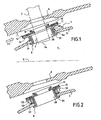
- Figures 1 to 3 show a sealing device 1 disposed between the body 2 of a spark plug 3 of the air-fuel mixture in the chamber 4 of an X-axis combustion chamber delimited radially towards the outside by a chamber wall 5 itself disposed inside a housing 6 carrying the spark plug 3.
- the housing 6 and the chamber wall 5 delimit between them an annular channel 7 in which circulates a flow of air F1 , resulting from the compressor, and intended for cooling the chamber wall, and possibly for cooling the casings and turbine, as well as for supplying a dilution air in the chamber 4.
- the radially inner end 3a of the spark plug 3 is arranged with a large clearance J in an opening 8 formed in the wall of the chamber 5.
- the clearance J is calculated sufficiently large to allow the relative displacements between the casing 6 and the wall of the chamber 5, as a result of the dilations.
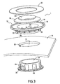
- the sealing device 1 comprises an annular plug guide 10 which surrounds the body 2 of the spark plug and which is in the form of a disk, slidably mounted in an annular housing 11 provided in the radially outer portion of a support annular 12 secured to the periphery 8a of the opening 8.
- the annular housing 11 is delimited by a cover 13 welded to an annular bead 14 formed at the periphery of the upper face 15 of the support 12.
- the height of the guide-plug 10, and the radial extension of the annular housing 11 relative to the The axis of the candle is significantly greater than the diameter of the candle guide 10 to allow free movement of the latter in the housing during relative movements of the candle and the chamber wall 5.
- the support 12 of the guide 10 is fixed, preferably by welding, on the radially outer portion of a chimney 20, whose diameter is adapted to that of the opening 8 and which has at its radially inner end a flange 21 intended to bear against the inner face of the periphery 8a of the opening 8.
- the chimney 20 and the flange 21 have splines 23 intended to receive a cooling air flow rate from the chimney 20 and especially from the flange 21 which, housed in the enclosure 4 of the combustion chamber, is subjected to high temperatures.
- the base of the chimney 20 has at its periphery a finger 24, and that the periphery 8a of the opening 8 has a notch 25.
- the finger 24 is intended to engage in the notch 25.
- This arrangement makes it necessary to mount the chimney 20 in the opening 8 in a predetermined angular position, so that the upper face of the flange 21 is applied accurately against the inner face of the periphery 8a, this flange face being shaped into function of the curvature of the chamber wall 5 around the opening 8.
- the flutes 23 are distributed regularly around the periphery of the chimney 20, extend axially over almost the entire height of the chimney 20 and extend radially on the face of the flange 21 which bears against the inner face of the flange 20. the chamber wall 5.
- These splines 23 are supplied with cooling air through passages provided in the support 12.
- the support 12 comprises a sleeve 30 surrounding the chimney 20 and whose base 31 is supported on the outer face of the periphery 8a, the periphery 8a of the opening 8 is thus clamped between the collar 21 and the base 31.
- the base 31 of the support 12 also has a notch 32 in which engages the upper end of the finger 24. This arrangement allows a unique angular positioning of the support 12 on the chimney 20 and this last in the opening 8.
- the sleeve 30 has ventilation holes 33 which must open opposite the flutes 23.
- the mounting of the sealing device 1 according to the first embodiment is easily understood.
- the chimney 20 is positioned in the opening 8, by introducing it through the enclosure 4.
- the finger 24 cooperating with the notch 25 ensures the angular positioning of the chimney 20.
- the support 12 is then positioned on the chimney 20 via the outside of the chamber wall 5.
- the cooperation of the finger 24 with the notch 32 ensures the angular positioning of the support 12.
- the support 12 is then fixed on the chimney 25 by welding.
- the guide candle 10 is placed on the upper face 15 of the support 12, then the lid 13 is fixed on the bead 14 by welding.
- the candle guide 10 is then free to move in the housing 11.
- the candle guide 10 has in its radially inner region a funnel 40 flared radially outwardly which allows to position the guide-candle 10 in the housing 11 when the setting up of the candle 3 on the casing 6.
- FIG. 2 shows a second embodiment of the invention, which differs from the first embodiment described above, in that the support 12 does not comprise a sleeve 30, this sleeve 30 being replaced by a locknut 50 cooperating with a thread formed at the periphery of the chimney 20, the latter however having splines 23 and a positioning finger 24.
- the periphery 8a of the opening 8 is clamped between the flange 21 and the nut 50.
- the support 12 which, in this case, is of low height, is fixed by welding on the radially outer end of the chimney 20.
- the feed air of the splines 23 flows in the space separating the support 12 from the upper face of the nut 50.
- the lower face of the support 12 may also have radial grooves.
- the support 12 may have on its underside a peripheral bead 51 surrounding the nut 50 and in which are provided slots 52 for feeding the splines 23.
- An elastic washer 53 may be interposed between the face outer circumference 8a and the nut 50 to take into account the curvature of the chamber wall 5.
Landscapes
- Engineering & Computer Science (AREA)
- Chemical & Material Sciences (AREA)
- Combustion & Propulsion (AREA)
- Mechanical Engineering (AREA)
- General Engineering & Computer Science (AREA)
- Ceramic Engineering (AREA)
- Portable Nailing Machines And Staplers (AREA)
- Spark Plugs (AREA)
- Cylinder Crankcases Of Internal Combustion Engines (AREA)
- Combustion Methods Of Internal-Combustion Engines (AREA)
Applications Claiming Priority (2)
| Application Number | Priority Date | Filing Date | Title |
|---|---|---|---|
| FR0307511A FR2856466B1 (fr) | 2003-06-20 | 2003-06-20 | Dispositif d'etancheite de bougie non soude sur la paroi de chambre |
| FR0307511 | 2003-06-20 |
Publications (2)
| Publication Number | Publication Date |
|---|---|
| EP1489360A1 EP1489360A1 (fr) | 2004-12-22 |
| EP1489360B1 true EP1489360B1 (fr) | 2006-05-03 |
Family
ID=33396827
Family Applications (1)
| Application Number | Title | Priority Date | Filing Date |
|---|---|---|---|
| EP04291486A Expired - Lifetime EP1489360B1 (fr) | 2003-06-20 | 2004-06-14 | Dispositif d'étanchéité de bougie non soudé sur la paroi de chambre |
Country Status (9)
| Country | Link |
|---|---|
| US (1) | US7101173B2 (enExample) |
| EP (1) | EP1489360B1 (enExample) |
| JP (1) | JP4056992B2 (enExample) |
| CN (1) | CN1573051A (enExample) |
| CA (1) | CA2470069C (enExample) |
| DE (1) | DE602004000790T2 (enExample) |
| ES (1) | ES2264095T3 (enExample) |
| FR (1) | FR2856466B1 (enExample) |
| RU (1) | RU2332578C2 (enExample) |
Families Citing this family (41)
| Publication number | Priority date | Publication date | Assignee | Title |
|---|---|---|---|---|
| US7546739B2 (en) * | 2005-07-05 | 2009-06-16 | General Electric Company | Igniter tube and method of assembling same |
| FR2891350A1 (fr) * | 2005-09-29 | 2007-03-30 | Snecma Sa | Dispositif de guidage d'un element dans un orifice d'une paroi de chambre de combustion de turbomachine |
| US8479490B2 (en) * | 2007-03-30 | 2013-07-09 | Honeywell International Inc. | Combustors with impingement cooled igniters and igniter tubes for improved cooling of igniters |
| FR2920032B1 (fr) * | 2007-08-13 | 2014-08-22 | Snecma | Diffuseur d'une turbomachine |
| US20090293486A1 (en) * | 2007-10-26 | 2009-12-03 | Honeywell International, Inc. | Combustors with igniters having protrusions |
| FR2925147B1 (fr) * | 2007-12-14 | 2012-07-13 | Snecma | Dispositif de guidage d'un element dans un orifice d'une paroi de chambre de combustion de turbomachine |
| FR2927367B1 (fr) | 2008-02-11 | 2010-05-28 | Snecma | Dispositif de montage d'une bougie d'allumage dans une chambre de combustion de moteur a turbine a gaz |
| US8454350B2 (en) * | 2008-10-29 | 2013-06-04 | General Electric Company | Diluent shroud for combustor |
| GB0918169D0 (en) * | 2009-10-19 | 2009-12-02 | Rolls Royce Plc | Fuel injector mounting system |
| US8726631B2 (en) * | 2009-11-23 | 2014-05-20 | Honeywell International Inc. | Dual walled combustors with impingement cooled igniters |
| CN102155329A (zh) * | 2011-03-30 | 2011-08-17 | 重庆长安汽车股份有限公司 | 一种发动机凸轮轴盖与气缸盖罩的密封结构 |
| DE102011016917A1 (de) | 2011-04-13 | 2012-10-18 | Rolls-Royce Deutschland Ltd & Co Kg | Gasturbinenbrennkammer mit einer Halterung einer Dichtung für ein Anbauteil |
| US9157638B2 (en) * | 2012-01-31 | 2015-10-13 | General Electric Company | Adaptor assembly for removable components |
| FR2988436B1 (fr) * | 2012-03-26 | 2015-12-04 | Snecma | Dispositif de guidage d'une bougie d'allumage |
| US9249978B2 (en) * | 2012-07-03 | 2016-02-02 | Alstom Technology Ltd | Retaining collar for a gas turbine combustion liner |
| US8683805B2 (en) * | 2012-08-06 | 2014-04-01 | General Electric Company | Injector seal for a gas turbomachine |
| FR2996284B1 (fr) | 2012-10-02 | 2019-03-15 | Safran Aircraft Engines | Fond de chambre annulaire pour chambre de combustion de turbomachine d'aeronef, muni de perforations permettant un refroidissement par flux giratoire |
| US9587831B2 (en) * | 2012-11-27 | 2017-03-07 | United Technologies Corporation | Cooled combustor seal |
| US20140186160A1 (en) * | 2012-12-29 | 2014-07-03 | United Technologies Corporation | Slider seal |
| EP2971967B1 (en) | 2013-03-14 | 2018-03-21 | Rolls-Royce Corporation | Inverted cap igniter tube |
| US9989254B2 (en) * | 2013-06-03 | 2018-06-05 | General Electric Company | Combustor leakage control system |
| FR3009341B1 (fr) * | 2013-08-05 | 2018-03-09 | Safran Aircraft Engines | Dispositif d'etancheite entre deux parties d'une machine comportant deux pieces, formant traversee coulissante et coupelle de retenue |
| FR3011620B1 (fr) * | 2013-10-04 | 2018-03-09 | Snecma | Chambre de combustion de turbomachine pourvue d'un passage d'entree d'air ameliore en aval d'un orifice de passage de bougie |
| US10156189B2 (en) * | 2014-01-28 | 2018-12-18 | Pratt & Whitney Canada Corp. | Combustor igniter assembly |
| EP2927595B1 (en) * | 2014-04-02 | 2019-11-13 | United Technologies Corporation | Grommet assembly and method of design |
| FR3022613B1 (fr) * | 2014-06-24 | 2019-04-19 | Safran Helicopter Engines | Bossage pour chambre de combustion. |
| FR3022480A1 (fr) * | 2014-06-24 | 2015-12-25 | Turbomeca | Machine pour sertir un bossage de chambre de combustion. |
| DE102014214775A1 (de) | 2014-07-28 | 2016-01-28 | Rolls-Royce Deutschland Ltd & Co Kg | Fluggasturbine mit einer Dichtung zur Abdichtung einer Zündkerze an der Brennkammerwand einer Gasturbine |
| US20160115874A1 (en) * | 2014-10-28 | 2016-04-28 | Solar Turbines Incorporated | Liner grommet assembly |
| FR3033028B1 (fr) * | 2015-02-25 | 2019-12-27 | Safran Helicopter Engines | Chambre de combustion de turbomachine comportant une piece penetrante avec ouverture |
| US9847702B2 (en) * | 2015-06-08 | 2017-12-19 | General Electric Company | In-situ method for sealing fluid cooled conduits for a generator |
| US10145559B2 (en) | 2015-12-15 | 2018-12-04 | General Electric Company | Gas turbine engine with igniter stack or borescope mount having noncollinear cooling passages |
| US20180030899A1 (en) * | 2016-07-27 | 2018-02-01 | Honda Motor Co., Ltd. | Structure for supporting spark plug for gas turbine engine |
| US11242804B2 (en) | 2017-06-14 | 2022-02-08 | General Electric Company | Inleakage management apparatus |
| SE540912E (en) * | 2017-09-12 | 2021-02-16 | Roxtec Ab | Extension frame |
| FR3081211B1 (fr) * | 2018-05-16 | 2021-02-26 | Safran Aircraft Engines | Ensemble pour une chambre de combustion de turbomachine |
| US11022308B2 (en) * | 2018-05-31 | 2021-06-01 | Honeywell International Inc. | Double wall combustors with strain isolated inserts |
| US11492972B2 (en) * | 2019-12-30 | 2022-11-08 | General Electric Company | Differential alpha variable area metering |
| CN113494362B (zh) * | 2020-04-08 | 2022-12-16 | 中国航发商用航空发动机有限责任公司 | 点火电嘴安装组件、燃烧室以及航空发动机 |
| CN119664504A (zh) * | 2023-09-19 | 2025-03-21 | 中国航发商用航空发动机有限责任公司 | 点火电嘴及航空发动机 |
| CN119222011B (zh) * | 2024-12-04 | 2025-02-18 | 西北工业大学 | 一种复合材料多维变刚度机匣结构 |
Family Cites Families (11)
| Publication number | Priority date | Publication date | Assignee | Title |
|---|---|---|---|---|
| US2693082A (en) * | 1951-04-04 | 1954-11-02 | Gen Motors Corp | Gas turbine fuel igniter |
| GB1402540A (en) * | 1971-10-05 | 1975-08-13 | Lucas Industries Ltd | Mounting arrangements for fuel sprayers |
| US3990834A (en) * | 1973-09-17 | 1976-11-09 | General Electric Company | Cooled igniter |
| US4128824A (en) * | 1977-09-29 | 1978-12-05 | Rca Corporation | Multilayered deflection yoke |
| US5687572A (en) * | 1992-11-02 | 1997-11-18 | Alliedsignal Inc. | Thin wall combustor with backside impingement cooling |
| RU2056688C1 (ru) * | 1994-03-14 | 1996-03-20 | Юрий Дмитриевич Калашников | Свеча зажигания |
| US6351949B1 (en) * | 1999-09-03 | 2002-03-05 | Allison Advanced Development Company | Interchangeable combustor chute |
| US6499993B2 (en) * | 2000-05-25 | 2002-12-31 | General Electric Company | External dilution air tuning for dry low NOX combustors and methods therefor |
| US6557350B2 (en) * | 2001-05-17 | 2003-05-06 | General Electric Company | Method and apparatus for cooling gas turbine engine igniter tubes |
| US6715279B2 (en) * | 2002-03-04 | 2004-04-06 | General Electric Company | Apparatus for positioning an igniter within a liner port of a gas turbine engine |
| US6920762B2 (en) * | 2003-01-14 | 2005-07-26 | General Electric Company | Mounting assembly for igniter in a gas turbine engine combustor having a ceramic matrix composite liner |
-
2003
- 2003-06-20 FR FR0307511A patent/FR2856466B1/fr not_active Expired - Fee Related
-
2004
- 2004-06-11 CA CA2470069A patent/CA2470069C/fr not_active Expired - Lifetime
- 2004-06-14 ES ES04291486T patent/ES2264095T3/es not_active Expired - Lifetime
- 2004-06-14 DE DE602004000790T patent/DE602004000790T2/de not_active Expired - Lifetime
- 2004-06-14 EP EP04291486A patent/EP1489360B1/fr not_active Expired - Lifetime
- 2004-06-17 JP JP2004179386A patent/JP4056992B2/ja not_active Expired - Fee Related
- 2004-06-18 RU RU2004118676/06A patent/RU2332578C2/ru active
- 2004-06-18 US US10/870,051 patent/US7101173B2/en not_active Expired - Lifetime
- 2004-06-21 CN CNA2004100600308A patent/CN1573051A/zh active Pending
Also Published As
| Publication number | Publication date |
|---|---|
| RU2004118676A (ru) | 2006-01-10 |
| ES2264095T3 (es) | 2006-12-16 |
| JP4056992B2 (ja) | 2008-03-05 |
| JP2005009856A (ja) | 2005-01-13 |
| US7101173B2 (en) | 2006-09-05 |
| DE602004000790T2 (de) | 2007-05-31 |
| DE602004000790D1 (de) | 2006-06-08 |
| FR2856466A1 (fr) | 2004-12-24 |
| EP1489360A1 (fr) | 2004-12-22 |
| CN1573051A (zh) | 2005-02-02 |
| CA2470069C (fr) | 2012-03-20 |
| US20050028528A1 (en) | 2005-02-10 |
| RU2332578C2 (ru) | 2008-08-27 |
| FR2856466B1 (fr) | 2005-08-26 |
| CA2470069A1 (fr) | 2004-12-20 |
Similar Documents
| Publication | Publication Date | Title |
|---|---|---|
| EP1489360B1 (fr) | Dispositif d'étanchéité de bougie non soudé sur la paroi de chambre | |
| EP1734305B1 (fr) | Assemblage d'une chambre de combustion annulaire de turbomachine | |
| EP1265034B1 (fr) | Accrochage de chambre de combustion CMC de turbomachine par pattes brasées | |
| EP1265035B1 (fr) | Liaison de chambre de combustion CMC de turbomachine en deux parties | |
| CA2726016A1 (fr) | Ensemble d'un disque de turbine d'un moteur a turbine a gaz et d'un tourillon support de palier, circuit de refroidissement d'un disque de turbine d'un tel ensemble | |
| WO2015097355A1 (fr) | Ensemble de fixation d'un bougie de turbomachine | |
| CA2581532A1 (fr) | Habillage de carter dans un turboreacteur | |
| EP2501996A1 (fr) | Chambre de combustion avec bougie d'allumage ventilee | |
| FR3077097A1 (fr) | Dispositif de refroidissement pour une turbine d'une turbomachine | |
| EP1731839A2 (fr) | Système de fixation d'un système d'injection sur un fond de chambre de combustion de turboréacteur et procède de fixation | |
| FR3020865A1 (fr) | Chambre annulaire de combustion | |
| CA2891072A1 (fr) | Support de tube d'evacuation d'air dans une turbomachine | |
| EP2048324B1 (fr) | Stator de turbine pour turbomachine d'aeronef integrant un dispositif d'amortissement de vibrations | |
| CA2952329C (fr) | Ensemble pour chambre de combustion de turbomachine comprenant un bossage et un element annulaire | |
| FR2998038A1 (fr) | Chambre de combustion pour une turbomachine | |
| FR3026827B1 (fr) | Chambre de combustion de turbomachine | |
| CA2582624C (fr) | Bras accroche-flammes d'une chambre de post-combustion | |
| EP2598803A2 (fr) | Systeme d'injection de carburant pour turbo-reacteur et procede d'assemblage d'un tel systeme d'injection | |
| EP3760927B1 (en) | Gas turbine engine combustor | |
| WO2021209711A1 (fr) | Bougie pour chambre de combustion monobloc | |
| FR3094398A1 (fr) | Ensemble pour un rotor de turbomachine | |
| EP3568638B1 (fr) | Chambre de combustion pour turbomachine | |
| FR2903151A1 (fr) | Dispositif de ventilation d'un carter d'echappement dans une turbomachine | |
| EP4515093A1 (fr) | Ensemble pour turbomachine | |
| FR2694600A1 (fr) | Silencieux à enveloppe coulissante. |
Legal Events
| Date | Code | Title | Description |
|---|---|---|---|
| PUAI | Public reference made under article 153(3) epc to a published international application that has entered the european phase |
Free format text: ORIGINAL CODE: 0009012 |
|
| 17P | Request for examination filed |
Effective date: 20040622 |
|
| AK | Designated contracting states |
Kind code of ref document: A1 Designated state(s): AT BE BG CH CY CZ DE DK EE ES FI FR GB GR HU IE IT LI LU MC NL PL PT RO SE SI SK TR |
|
| AX | Request for extension of the european patent |
Extension state: AL HR LT LV MK |
|
| AKX | Designation fees paid |
Designated state(s): DE ES FR GB IT SE |
|
| RAP1 | Party data changed (applicant data changed or rights of an application transferred) |
Owner name: SNECMA |
|
| GRAP | Despatch of communication of intention to grant a patent |
Free format text: ORIGINAL CODE: EPIDOSNIGR1 |
|
| GRAS | Grant fee paid |
Free format text: ORIGINAL CODE: EPIDOSNIGR3 |
|
| GRAA | (expected) grant |
Free format text: ORIGINAL CODE: 0009210 |
|
| AK | Designated contracting states |
Kind code of ref document: B1 Designated state(s): DE ES FR GB IT SE |
|
| REG | Reference to a national code |
Ref country code: GB Ref legal event code: FG4D Free format text: NOT ENGLISH |
|
| REF | Corresponds to: |
Ref document number: 602004000790 Country of ref document: DE Date of ref document: 20060608 Kind code of ref document: P |
|
| REG | Reference to a national code |
Ref country code: SE Ref legal event code: TRGR |
|
| GBT | Gb: translation of ep patent filed (gb section 77(6)(a)/1977) |
Effective date: 20060814 |
|
| REG | Reference to a national code |
Ref country code: ES Ref legal event code: FG2A Ref document number: 2264095 Country of ref document: ES Kind code of ref document: T3 |
|
| PLBE | No opposition filed within time limit |
Free format text: ORIGINAL CODE: 0009261 |
|
| STAA | Information on the status of an ep patent application or granted ep patent |
Free format text: STATUS: NO OPPOSITION FILED WITHIN TIME LIMIT |
|
| 26N | No opposition filed |
Effective date: 20070206 |
|
| PGFP | Annual fee paid to national office [announced via postgrant information from national office to epo] |
Ref country code: SE Payment date: 20070528 Year of fee payment: 4 |
|
| EUG | Se: european patent has lapsed | ||
| PG25 | Lapsed in a contracting state [announced via postgrant information from national office to epo] |
Ref country code: SE Free format text: LAPSE BECAUSE OF NON-PAYMENT OF DUE FEES Effective date: 20080615 |
|
| PGFP | Annual fee paid to national office [announced via postgrant information from national office to epo] |
Ref country code: ES Payment date: 20120614 Year of fee payment: 9 |
|
| REG | Reference to a national code |
Ref country code: ES Ref legal event code: FD2A Effective date: 20150709 |
|
| PG25 | Lapsed in a contracting state [announced via postgrant information from national office to epo] |
Ref country code: ES Free format text: LAPSE BECAUSE OF NON-PAYMENT OF DUE FEES Effective date: 20130615 |
|
| REG | Reference to a national code |
Ref country code: FR Ref legal event code: PLFP Year of fee payment: 13 |
|
| REG | Reference to a national code |
Ref country code: FR Ref legal event code: PLFP Year of fee payment: 14 |
|
| REG | Reference to a national code |
Ref country code: FR Ref legal event code: CD Owner name: SAFRAN AIRCRAFT ENGINES Effective date: 20170717 |
|
| REG | Reference to a national code |
Ref country code: FR Ref legal event code: PLFP Year of fee payment: 15 |
|
| PGFP | Annual fee paid to national office [announced via postgrant information from national office to epo] |
Ref country code: IT Payment date: 20230523 Year of fee payment: 20 Ref country code: FR Payment date: 20230523 Year of fee payment: 20 Ref country code: DE Payment date: 20230523 Year of fee payment: 20 |
|
| PGFP | Annual fee paid to national office [announced via postgrant information from national office to epo] |
Ref country code: GB Payment date: 20230523 Year of fee payment: 20 |
|
| REG | Reference to a national code |
Ref country code: DE Ref legal event code: R071 Ref document number: 602004000790 Country of ref document: DE |
|
| PG25 | Lapsed in a contracting state [announced via postgrant information from national office to epo] |
Ref country code: GB Free format text: LAPSE BECAUSE OF EXPIRATION OF PROTECTION Effective date: 20240613 |
|
| PG25 | Lapsed in a contracting state [announced via postgrant information from national office to epo] |
Ref country code: GB Free format text: LAPSE BECAUSE OF EXPIRATION OF PROTECTION Effective date: 20240613 |