EP1489263A1 - Shaft-hub connection - Google Patents
Shaft-hub connection Download PDFInfo
- Publication number
- EP1489263A1 EP1489263A1 EP03405441A EP03405441A EP1489263A1 EP 1489263 A1 EP1489263 A1 EP 1489263A1 EP 03405441 A EP03405441 A EP 03405441A EP 03405441 A EP03405441 A EP 03405441A EP 1489263 A1 EP1489263 A1 EP 1489263A1
- Authority
- EP
- European Patent Office
- Prior art keywords
- shaft
- thread
- attachment
- shaft attachment
- axis
- Prior art date
- Legal status (The legal status is an assumption and is not a legal conclusion. Google has not performed a legal analysis and makes no representation as to the accuracy of the status listed.)
- Granted
Links
Images


Classifications
-
- F—MECHANICAL ENGINEERING; LIGHTING; HEATING; WEAPONS; BLASTING
- F01—MACHINES OR ENGINES IN GENERAL; ENGINE PLANTS IN GENERAL; STEAM ENGINES
- F01D—NON-POSITIVE DISPLACEMENT MACHINES OR ENGINES, e.g. STEAM TURBINES
- F01D5/00—Blades; Blade-carrying members; Heating, heat-insulating, cooling or antivibration means on the blades or the members
- F01D5/02—Blade-carrying members, e.g. rotors
- F01D5/025—Fixing blade carrying members on shafts
-
- F—MECHANICAL ENGINEERING; LIGHTING; HEATING; WEAPONS; BLASTING
- F05—INDEXING SCHEMES RELATING TO ENGINES OR PUMPS IN VARIOUS SUBCLASSES OF CLASSES F01-F04
- F05D—INDEXING SCHEME FOR ASPECTS RELATING TO NON-POSITIVE-DISPLACEMENT MACHINES OR ENGINES, GAS-TURBINES OR JET-PROPULSION PLANTS
- F05D2220/00—Application
- F05D2220/40—Application in turbochargers
-
- F—MECHANICAL ENGINEERING; LIGHTING; HEATING; WEAPONS; BLASTING
- F05—INDEXING SCHEMES RELATING TO ENGINES OR PUMPS IN VARIOUS SUBCLASSES OF CLASSES F01-F04
- F05D—INDEXING SCHEME FOR ASPECTS RELATING TO NON-POSITIVE-DISPLACEMENT MACHINES OR ENGINES, GAS-TURBINES OR JET-PROPULSION PLANTS
- F05D2250/00—Geometry
- F05D2250/20—Three-dimensional
- F05D2250/23—Three-dimensional prismatic
- F05D2250/232—Three-dimensional prismatic conical
-
- F—MECHANICAL ENGINEERING; LIGHTING; HEATING; WEAPONS; BLASTING
- F05—INDEXING SCHEMES RELATING TO ENGINES OR PUMPS IN VARIOUS SUBCLASSES OF CLASSES F01-F04
- F05D—INDEXING SCHEME FOR ASPECTS RELATING TO NON-POSITIVE-DISPLACEMENT MACHINES OR ENGINES, GAS-TURBINES OR JET-PROPULSION PLANTS
- F05D2250/00—Geometry
- F05D2250/20—Three-dimensional
- F05D2250/28—Three-dimensional patterned
- F05D2250/281—Three-dimensional patterned threaded
Definitions
- the invention relates to the field of shaft / hub connections.
- Turbochargers to increase the performance of reciprocating engines include a through Engine exhaust driven turbine and one via a torque transmitting Compressor shaft connected to the turbine.
- Turbocharger for smaller engine outputs advantageously have a radial compressor made of aluminum without continuous Central bore on, as known from DE 44 44 082.
- the compressor wheel can be solved for manufacturing and maintenance reasons with the Turbine shaft connected.
- the compressor wheel is either directly or via a Intermediate sleeve made of steel or bronze on a stub shaft with a conventional thread screwed on. At least one offset to the thread Cylindrical or conical centering seat ensures the centering of the compressor wheel regarding the wave.
- the invention is therefore based on the object, a connection of the beginning to create the type mentioned, which with improved torque transmission allows reduced axial preload.
- the radial pressure that is decisive for torque transmission is thanks to the flat Angle between the load-bearing, with their large surfaces friction flanks lying on top of each other and the axis correspondingly larger than at conventional threaded connections. This allows the axial preload between the two parts to be connected are reduced accordingly.
- the flat-shaped supporting flanks enable an improved Centering the shaft attachment and shaft.
- the shaft attachment is exemplary as one in shape and size approximately Corresponding cylindrical counterpart shown. As a rule, it is in the shaft attachment around a wheel-shaped part, such as the compressor wheel Turbocharger.
- the shaft has an external thread in the area of the connection point.
- the external thread at the shaft end in the form of a Threaded pin 10 is formed.
- the shaft and Shaft attachment For the axial positioning of the shaft attachment with respect to the shaft, the shaft and Shaft attachment an axial stop 11 and 21.
- the two axial stops have in the Usually with high precision manufactured parallel surfaces, with which they make a significant contribution to the concentricity of the shaft attachment and shaft. Between Axial stops, further parts can be arranged, for example as in the figure shown a sealing or damping disc 3rd
- FIG. 2 shows a view of a section through the shaft axis compound according to the invention.
- the two axial stops 11 and 12 are at Screwing the shaft attachment onto the shaft, which causes the Shaft attachment is biased against the shaft.
- the shaft attachment is usually a larger one, made of a relatively soft one Material manufactured part can in the area of the threaded connection through the Sliding a hard steel sleeve 4 on the shaft extension of the Shaft attachment can be prevented by the threaded pin.
- the special design of the thread according to the invention is enlarged in FIG. 3 shown.
- the thread has load-bearing flanks 15 and 25 as well as manufacturing-related, edges 16 and 26 not loaded.
- the supporting flanks 15 and 25 enclose with the axis A of the shaft and the shaft attachment a very flat angle ⁇ .
- the Flank angle ⁇ is ideally 5 ° to 15 °, depending on the requirements of the Connection or the material of the parts to be connected, however, also in the range of 0 ° up to 45 ° or even 60 °.
- the flatter this angle ⁇ the smaller it is axial preload, which can be transmitted through the thread to the two parts to be connected, the shaft and the shaft attachment using the axial stops to brace against each other.
- the decisive radial pressure for torque transmission is corresponding to a flat angle between the supporting flanks and the axis greater.
- the large flanks of the load-bearing flanks are friction-locked on each other.
- the thread according to the invention is used to further reduce the pretensioning force Multi-course, preferably 3-course. Given a given Flank angle less deep thread grooves and therefore less Cross-sectional weaknesses. In addition, a 3-start thread leads due to the 3-fold cyclic Symmetry for an improved centering of the shaft attachment on the Wave.
- the flat-shaped supporting flanks bring a further improvement in the Centering of the shaft attachment on the shaft.
- the flat thread according to the invention has significantly larger fillet radii 17 and 27. That’s why Thread according to the invention has practically no notch effect and is dynamic Torque fluctuations are much more resilient than a conventional thread.
- the thread as shown in the different figures, is a conical thread improves compared to a cylindrical version Force transmission while the screwing distances are shortened.
- the steeper the angle ⁇ of the Cone the shorter the screw-on distances, since sometimes several are used when screwing on Threads can be skipped.
- Figures 4 to 7 show detailed individual views of the shaft and the shaft attachment.
- the Axial views show the three-start thread.
- the three threads are arranged offset by 120 °.
- the arrangement of the threaded pin and the bore, or the outer and of the internal thread can also be interchanged, so that on the shaft attachment Threaded pin is arranged and the corresponding hole in the shaft end is let in.
- the threaded pin need not be designed as a stub.
- the external thread can be arranged in a central region of a rod-shaped shaft, the bore in the shaft attachment being correspondingly deep for the thread extension, or must be continuous.
Landscapes
- Engineering & Computer Science (AREA)
- Mechanical Engineering (AREA)
- General Engineering & Computer Science (AREA)
- Supercharger (AREA)
- Structures Of Non-Positive Displacement Pumps (AREA)
Abstract
Description
Die Erfindung bezieht sich auf das Gebiet der Wellen-/Nabenverbindungen.The invention relates to the field of shaft / hub connections.
Sie betrifft die Verbindung einer Welle mit einem Wellenaufsatz mittels einem Gewinde
gemäss dem Oberbegriff des Patentanspruchs 1. Sie betrifft ferner einen Turbolader,
dessen Turbinenwelle mit dem Verdichterrad entsprechend verbunden ist.It relates to the connection of a shaft with a shaft attachment by means of a thread
according to the preamble of
Turbolader zur Leistungssteigerung von Hubkolbenmotoren umfassen eine durch Motorenabgase angetriebene Turbine und einen über eine drehmomentübertragende Welle mit der Turbine verbundenen Verdichter. Turbolader für kleinere Motorenleistungen weisen vorteilhaft einen Radialverdichter aus Aluminium ohne durchgehende Zentralbohrung auf, wie etwa aus DE 44 44 082 bekannt.Turbochargers to increase the performance of reciprocating engines include a through Engine exhaust driven turbine and one via a torque transmitting Compressor shaft connected to the turbine. Turbocharger for smaller engine outputs advantageously have a radial compressor made of aluminum without continuous Central bore on, as known from DE 44 44 082.
Das Verdichterrad ist dabei aus Herstellungs- und Wartungsgründen lösbar mit der Turbinenwelle verbunden.The compressor wheel can be solved for manufacturing and maintenance reasons with the Turbine shaft connected.
Bei den bekannten Lösungen wird das Verdichterrad entweder direkt oder über eine Zwischenbüchse aus Stahl oder Bronze auf einen Wellenstummel mit einem konventionellen Gewinde aufgeschraubt. Mindestens ein zum Gewinde versetzter, zylindrischer oder konischer Zentriersitz sorgt für die Zentrierung des Verdichterrades bezüglich der Welle.In the known solutions, the compressor wheel is either directly or via a Intermediate sleeve made of steel or bronze on a stub shaft with a conventional thread screwed on. At least one offset to the thread Cylindrical or conical centering seat ensures the centering of the compressor wheel regarding the wave.
Bei einer solchen Wellen-/ Verdichterradverbindung wird das Verdichterrad gegen einen axialen Anschlag an der Welle verspannt. Die Drehmomentübertragung erfolgt im Gewinde reibschlüssig über die in axialer Richtung aneinandergepressten tragenden Gewindeflanken. Bei herkömmlichen Gewinden stehen die tragenden Gewindeflanken in einem möglichst steilen Winkel zur Wellenachse, damit die Vorspannkraft im wesentlichen normal zur Oberfläche der tragenden Gewindeflanken wirken kann. With such a shaft / compressor wheel connection, the compressor wheel is against one axial stop clamped on the shaft. The torque transmission takes place in the Threads frictionally over the load-bearing parts that are pressed together in the axial direction Thread flanks. With conventional threads, the load-bearing thread flanks are in an angle that is as steep as possible to the shaft axis, so that the prestressing force essentially can act normal to the surface of the supporting thread flanks.
Jüngste Leistungssteigerungen der Verdichter von Turbolader machen eine verbesserte Drehmomentübertragung von Welle auf Verdichterrad notwendig. Bei herkömmlichen Verbindungen bedeutet dies, dass die Vorspannkraft erhöht werden muss, um die tragenden Flanken der Gewinde in axialer Richtung stärker aneinander zu pressen. Dies führt jedoch zu einer reduzierten Fügestellendämpfung zwischen den miteinander verbundenen Teilen. Weiter einschränkend ist zudem die bei herkömmlichen Gewinden durch den Querschnittssprung von Gewindegang zu Gewindegang hervorgerufene Kerbwirkung.Recent increases in performance of turbocharger compressors make an improved one Torque transmission from shaft to compressor wheel necessary. With conventional This means that the pretension must be increased to the connections the flanks of the threads in the axial direction. This however leads to a reduced joint damping between the two connected parts. Another limitation is that of conventional threads caused by the cross-sectional jump from thread to thread Notch effect.
Der Erfindung liegt folglich die Aufgabe zugrunde, eine Verbindung der eingangs genannten art zu schaffen, welche eine verbesserte Drehmomentübertragung bei reduzierter axialen Vorspannung ermöglicht.The invention is therefore based on the object, a connection of the beginning to create the type mentioned, which with improved torque transmission allows reduced axial preload.
Erfindungsgemäss wird diese Aufgabe mit den Merkmalen des Patentanspruchs 1 gelöst.According to the invention, this object is achieved with the features of
Bei der erfindungsgemässen Verbindung einer Welle mit einem Wellenaufsatz mittels einem Gewinde, bei welcher entweder in den Wellenaufsatz oder in das Wellenende eine Bohrung mit einem Innengewinde eingelassen ist, und die Welle oder der Wellenaufsatz einen entsprechenden, in die Gewindebohrung einbringbaren Zapfen mit einem Aussengewinde aufweist, und an der Welle und am Wellenaufsatz jeweils ein Axialanschlag angeordnet ist, weisen das Innen- und das Aussengewinde zur Achse von Welle und Wellenaufsatz hin flache, drehmomentübertragende Flanken auf, welche durch gegenseitige Verdrehung von Welle und Wellenaufsatz, unter Zusammenwirkung der Axialanschläge mittels radialer Pressung reibschlüssig miteinander verbindbar sind.When connecting a shaft to a shaft attachment according to the invention by means of a thread in which either in the shaft attachment or in the shaft end Bore is embedded with an internal thread, and the shaft or the shaft attachment a corresponding pin that can be inserted into the threaded bore with a Has external thread, and each on the shaft and on the shaft attachment Axial stop is arranged, the internal and external threads to the axis of Shaft and shaft attachment towards flat, torque-transmitting flanks, which through mutual rotation of shaft and shaft attachment, in cooperation with the Axial stops can be frictionally connected to one another by means of radial pressure.
Die für die Drehmomentübertragung entscheidende radiale Pressung ist dank dem flachen Winkel zwischen den tragenden, mit ihren grossen Oberflächen reibschlüssig aufeinanderliegenden Flanken und der Achse entsprechend grösser als bei herkömmlichen Gewindeverbindungen. Dadurch kann die axiale Vorspannkraft zwischen den beiden zu verbindenden Teilen entsprechend reduziert werden.The radial pressure that is decisive for torque transmission is thanks to the flat Angle between the load-bearing, with their large surfaces friction flanks lying on top of each other and the axis correspondingly larger than at conventional threaded connections. This allows the axial preload between the two parts to be connected are reduced accordingly.
Zudem ermöglichen die flach ausgebildeten tragenden Flanken ein verbessertes Zentrieren von Wellenaufsatz und Welle.In addition, the flat-shaped supporting flanks enable an improved Centering the shaft attachment and shaft.
Weitere Vorteile ergeben sich aus den abhängigen Ansprüchen. Further advantages result from the dependent claims.
Im folgenden ist anhand der Figuren ein Ausführungsbeispiel der erfindungsgemässen Verbindung schematisch dargestellt und näher erläutert. In allen Figuren sind gleichwirkende Elemente mit gleichen Bezugszeichen versehen. Es zeigen:
- Fig. 1
- eine Ansicht auf eine Welle mit einem Wellenaufsatz mit einer erfindungsgemässen Verbindung,
- Fig. 2
- eine Ansicht auf einen entlang der Wellenachse geführten Schnitt durch die Verbindung nach Fig. 1,
- Fig. 3
- einen vergrössert dargestellten Ausschnitt III- III der Verbindung nach Fig. 2,
- Fig. 4
- eine Ansicht in Achsrichtung auf die Welle nach Fig. 1,
- Fig. 5
- eine Ansicht senkrecht zur Achse auf die Welle nach Fig. 1,
- Fig. 6
- eine Ansicht in Achsrichtung auf den Wellenaufsatz nach Fig. 1, und
- Fig. 7
- eine Ansicht auf einen entlang VII-VII geführten Schnitt durch den Wellenaufsatz nach Fig. 6,
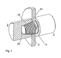
- Fig. 1
- 2 shows a view of a shaft with a shaft attachment with a connection according to the invention,
- Fig. 2
- 2 shows a view of a section taken along the shaft axis through the connection according to FIG. 1,
- Fig. 3
- 3 shows an enlarged section III-III of the connection according to FIG. 2,
- Fig. 4
- 2 shows a view in the axial direction of the shaft according to FIG. 1,
- Fig. 5
- 2 shows a view perpendicular to the axis of the shaft according to FIG. 1,
- Fig. 6
- a view in the axial direction of the shaft attachment of FIG. 1, and
- Fig. 7
- 6 shows a view of a section taken along VII-VII through the shaft attachment according to FIG. 6,
Fig. 1 zeigt eine Welle 1 und einen erfindungsgemäss mit der Welle verbundenen
Wellenaufsatz 2. Der Wellenaufsatz ist beispielhaft als ein in Form und Grösse etwa der
Welle entsprechendes, zylindrisches Gegenstück abgebildet. In der Regel handelt es sich
beim Wellenaufsatz um ein radförmiges Teil, wie etwa das Verdichterrad eines
Turboladers.1 shows a
Die Welle weist im Bereich der Verbindungsstelle ein Aussengewinde auf. In der
dargestellten Ausführungsform ist das Aussengewinde am Wellenende in Form eines
Gewindezapfens 10 ausgebildet ist. In den Wellenaufsatz ist eine entsprechende Bohrung
20 eingelassen, welche mit einem Innengewinde ausgestattet ist.The shaft has an external thread in the area of the connection point. In the
The embodiment shown is the external thread at the shaft end in the form of a
Threaded
Zur axialen Positionierung des Wellenaufsatzes bezüglich der Welle weisen Welle und
Wellenaufsatz einen Axialanschlag 11 und 21 auf. Die beiden Axialanschläge haben in der
Regel mit hoher Präzision gefertigte zueinander parallele Oberflächen, womit sie
wesentlich zum Rundlauf von Wellenaufsatz und Welle beitragen. Zwischen den
Axialanschlägen können, weitere Teile angeordnet sein, beispielsweise wie in der Figur
dargestellt eine Dicht- oder Dämpfungsscheibe 3.For the axial positioning of the shaft attachment with respect to the shaft, the shaft and
Shaft attachment an
Fig. 2 zeigt eine Ansicht eines entlang der Wellenachse geführten Schnittes durch die
erfindungsgemässe Verbindung. Die beiden Axialanschläge 11 und 12 werden beim
Aufschrauben des Wellenaufsatzes auf die Welle zusammengepresst, wodurch der
Wellenaufsatz gegen die Welle vorgespannt wird.FIG. 2 shows a view of a section through the shaft axis
compound according to the invention. The two
Da es sich beim Wellenaufsatz in der Regel um ein grösseres, aus einem relativ weichen
Material gefertigtes Teil handelt, kann im Bereich der Gewindeverbindung durch das
Aufschieben einer harten Stahlbüchse 4 auf den Wellenaufsatz die Ausdehnung des
Wellenaufsatzes durch den Gewindezapfen verhindert werden.Since the shaft attachment is usually a larger one, made of a relatively soft one
Material manufactured part can in the area of the threaded connection through the
Sliding a
Die spezielle, erfindungsgemässe Gestaltung des Gewindes ist in Fig. 3 vergrössert
dargestellt. Das Gewinde weist tragende Flanken 15 und 25 sowie herstellungsbedingte,
nicht belastete Flanken 16 und 26 auf. Die tragenden Flanken 15 und 25 umschliessen mit
der Achse A der Welle und des Wellenaufsatzes einen sehr flachen Winkel α. Der
Flankenwinkel α beträgt idealerweise 5° bis 15°, kann je nach Anforderung an die
Verbindung oder dem Material der zu verbindenden Teile jedoch auch im Bereich von 0°
bis 45° oder gar 60° ausgeführt werden. Je flacher dieser Winkel α, desto geringer ist die
axiale Vorspannkraft, welche durch das Gewinde übertragen werden kann, um die beiden
zu verbindenden Teile, die Welle und den Wellenaufsatz mit Hilfe der Axialanschläge
gegeneinander zu verspannen.The special design of the thread according to the invention is enlarged in FIG. 3
shown. The thread has load-
Dagegen ist die für die Drehmomentübertragung entscheidende radiale Pressung bei einem flachen Winkel zwischen den tragenden Flanken und der Achse entsprechend grösser. Die tragenden Flanken liegen mit ihren grossen Oberflächen reibschlüssig aufeinander auf.In contrast, the decisive radial pressure for torque transmission is corresponding to a flat angle between the supporting flanks and the axis greater. The large flanks of the load-bearing flanks are friction-locked on each other.
Zur weiteren Reduktion der Vorspannkraft wird das erfindungsgemässe Gewinde mehrgängig, vorzugsweise 3-gängig, ausgeführt. Dies ergibt bei gegebenem Flankenwinkel weniger tiefe Gewindefurchen und somit geringere Querschnittschwächungen. Zudem führt ein 3-gängiges Gewinde aufgrund der 3-fachzyklischen Symmetrie zu einer verbesserten Zentrierung des Wellenaufsatzes auf der Welle.The thread according to the invention is used to further reduce the pretensioning force Multi-course, preferably 3-course. Given a given Flank angle less deep thread grooves and therefore less Cross-sectional weaknesses. In addition, a 3-start thread leads due to the 3-fold cyclic Symmetry for an improved centering of the shaft attachment on the Wave.
Im Weiteren wird durch den grösseren Steigungswinkel der Windungen des mehrgängigen Gewindes der Aufdrehwinkel massiv reduziert. Furthermore, the larger pitch angle of the turns of the multi-course Thread the opening angle massively reduced.
Die flach ausgebildeten tragenden Flanken bringen eine weiter Verbesserung in der Zentrierung des Wellenaufsatzes auf der Welle.The flat-shaped supporting flanks bring a further improvement in the Centering of the shaft attachment on the shaft.
Gegenüber herkömmlichen Gewinden weist das erfindungsgemässe Flachgewinde
wesentlich grössere Ausrundungsradien 17 und 27 auf. Dadurch hat das
erfindungsgemässe Gewinde praktisch keine Kerbwirkung und ist bezüglich dynamischen
Drehmomentschwankungen wesentlich höher belastbar als ein herkömmliches Gewinde.Compared to conventional threads, the flat thread according to the invention has
significantly
Handelt es sich beim Gewinde, wie in den verschiedenen Figuren dargestellt, um ein konisches Gewinde verbessert sich gegenüber einer zylindrischen Ausführung die Krafteinleitung, während sich die Aufschraubwege verkürzen. Je steiler der Winkel β des Konus, desto kürzer sind die Aufschraubwege, da beim Aufschrauben bisweilen mehrere Gewindegänge übersprungen werden können.If the thread, as shown in the different figures, is a conical thread improves compared to a cylindrical version Force transmission while the screwing distances are shortened. The steeper the angle β of the Cone, the shorter the screw-on distances, since sometimes several are used when screwing on Threads can be skipped.
Figuren 4 bis 7 zeigen detaillierte Einzelansichten der Welle und des Wellenaufsatzes. Die Ansichten in Achsrichtung zeigen die dreigängigen Gewinde. Die drei Gewindegänge sind um je 120° versetzt angeordnet.Figures 4 to 7 show detailed individual views of the shaft and the shaft attachment. The Axial views show the three-start thread. The three threads are arranged offset by 120 °.
Die Anordnung des Gewindezapfens und der Bohrung, beziehungsweise des Aussen- und des Innengewindes kann auch vertauscht werden, so dass am Wellenaufsatz ein Gewindezapfen angeordnet ist und die entsprechende Bohrung in das Wellenende eingelassen ist.The arrangement of the threaded pin and the bore, or the outer and of the internal thread can also be interchanged, so that on the shaft attachment Threaded pin is arranged and the corresponding hole in the shaft end is let in.
Ferner braucht der Gewindezapfen nicht als Stummel ausgebildet zu sein. So kann etwa das Aussengewinde in einem Mittelbereich einer stangenförmigen Welle angeordnet sein, wobei für den Gewindefortsatz die Bohrung im Wellenaufsatz entsprechend tief, beziehungsweise durchgehend sein muss. Furthermore, the threaded pin need not be designed as a stub. For example the external thread can be arranged in a central region of a rod-shaped shaft, the bore in the shaft attachment being correspondingly deep for the thread extension, or must be continuous.
- AA
- Achseaxis
- αα
- Flankenwinkelflank angle
- ββ
- Konuswinkel des GewindesCone angle of the thread
- 11
- Welle, TurbinenwelleShaft, turbine shaft
- 1010
- Gewindezapfenthreaded pin
- 1111
- Wellenschultershaft shoulder
- 1515
- Tragende Flanke (Aussengewinde)Load-bearing flank (external thread)
- 1616
- Nichttragende Flanke (Aussengewinde)Non-load-bearing flank (external thread)
- 1717
- Ausrundung (Aussengewinde)Fillet (external thread)
- 22
- Wellenaufsatz, VerdichterradShaft attachment, compressor wheel
- 2020
- Gewindebohrungthreaded hole
- 2121
- Plananschlagbackstop
- 2525
- Tragende Flanke (Innengewinde)Load-bearing flank (internal thread)
- 2626
- Nichttragende Flanke (Innengewinde)Non-load-bearing flank (internal thread)
- 2727
- Ausrundung (Innengewinde)Fillet (internal thread)
- 33
- Zwischenkörper, DichtringIntermediate body, sealing ring
- 44
- Stahlhülsesteel sleeve
Claims (5)
an der Welle und am Wellenaufsatz jeweils ein Axialanschlag (11, 21) angeordnet ist, dadurch gekennzeichnet, dass
das Innen- und das Aussengewinde zur Achse von Welle und Wellenaufsatz (A) hin flache, drehmomentübertragende Flanken (15, 25) aufweisen, welche durch gegenseitige Verdrehung von Welle und Wellenaufsatz, unter Zusammenwirkung der Axialanschläge mittels radialer Pressung reibschlüssig miteinander verbindbar sind.Connection of a shaft (1) to a shaft attachment (2) by means of a thread, a bore (20) with an internal thread being inserted either in the shaft attachment or in the shaft end, and the shaft or the shaft attachment having a corresponding pin that can be inserted into the threaded bore (10) with an external thread, and
an axial stop (11, 21) is arranged on the shaft and on the shaft attachment, characterized in that
the internal and external threads have flat, torque-transmitting flanks (15, 25) towards the axis of the shaft and shaft attachment (A), which can be frictionally connected to one another by mutual rotation of the shaft and shaft attachment, in cooperation with the axial stops by means of radial pressure.
Priority Applications (3)
| Application Number | Priority Date | Filing Date | Title |
|---|---|---|---|
| DE50306502T DE50306502D1 (en) | 2003-06-19 | 2003-06-19 | Shaft / hub connection of a turbocharger |
| EP03405441A EP1489263B1 (en) | 2003-06-19 | 2003-06-19 | Turbocharger shaft-hub connection |
| US10/861,360 US6918723B2 (en) | 2003-06-19 | 2004-06-07 | Shaft/hub connection |
Applications Claiming Priority (1)
| Application Number | Priority Date | Filing Date | Title |
|---|---|---|---|
| EP03405441A EP1489263B1 (en) | 2003-06-19 | 2003-06-19 | Turbocharger shaft-hub connection |
Publications (2)
| Publication Number | Publication Date |
|---|---|
| EP1489263A1 true EP1489263A1 (en) | 2004-12-22 |
| EP1489263B1 EP1489263B1 (en) | 2007-02-14 |
Family
ID=33396093
Family Applications (1)
| Application Number | Title | Priority Date | Filing Date |
|---|---|---|---|
| EP03405441A Expired - Lifetime EP1489263B1 (en) | 2003-06-19 | 2003-06-19 | Turbocharger shaft-hub connection |
Country Status (3)
| Country | Link |
|---|---|
| US (1) | US6918723B2 (en) |
| EP (1) | EP1489263B1 (en) |
| DE (1) | DE50306502D1 (en) |
Cited By (1)
| Publication number | Priority date | Publication date | Assignee | Title |
|---|---|---|---|---|
| CN103846613A (en) * | 2014-02-12 | 2014-06-11 | 中国北方发动机研究所(天津) | Connection method and connection structure of tapered threads of impeller and rotating shaft of turbine of supercharger |
Families Citing this family (10)
| Publication number | Priority date | Publication date | Assignee | Title |
|---|---|---|---|---|
| JP2005030382A (en) * | 2003-06-18 | 2005-02-03 | Komatsu Ltd | Compressor of turbomachinery and its compressor impeller |
| US20070009340A1 (en) * | 2005-07-11 | 2007-01-11 | Van Cor Dale E | Conic threaded fastener and fastener system |
| NL2001433C2 (en) * | 2008-04-02 | 2009-10-05 | Bronswerk Heat Transfer Bv | Conical screw coupling. |
| DE102011051961A1 (en) * | 2011-07-20 | 2013-01-24 | Zf Lenksysteme Gmbh | Device for securing a unit |
| CN203306224U (en) | 2013-05-31 | 2013-11-27 | 深圳市大疆创新科技有限公司 | Propeller and aircraft provided with same |
| DE102013015563A1 (en) * | 2013-09-20 | 2015-03-26 | Abb Turbo Systems Ag | turbocharger |
| DE102013018005A1 (en) | 2013-11-29 | 2015-06-03 | Mtu Friedrichshafen Gmbh | Shaft-hub connection |
| US9889509B2 (en) * | 2014-05-05 | 2018-02-13 | Kennametal Inc. | Cutter heads with improved coupling |
| CN114375276A (en) * | 2019-10-09 | 2022-04-19 | 小鹰公司 | Short-distance take-off and landing carrier with forward swept wings |
| US20240239531A1 (en) * | 2022-08-09 | 2024-07-18 | Pete Bitar | Compact and Lightweight Drone Delivery Device called an ArcSpear Electric Jet Drone System Having an Electric Ducted Air Propulsion System and Being Relatively Difficult to Track in Flight |
Citations (4)
| Publication number | Priority date | Publication date | Assignee | Title |
|---|---|---|---|---|
| GB241211A (en) * | 1924-10-09 | 1927-01-10 | Fr De Filetage Indesserrable D | An improved self-locking nut and bolt |
| GB826136A (en) * | 1955-02-08 | 1959-12-31 | Voigtlaender Ag | Improvements in and relating to screw threads for optical apparatus |
| US4304428A (en) * | 1976-05-03 | 1981-12-08 | Grigorian Samvel S | Tapered screw joint and device for emergency recovery of boring tool from borehole with the use of said joint |
| DE3913974A1 (en) * | 1988-05-31 | 1989-12-14 | Siemens Ag | Arrangement for the releasable connection of two bodies, in particular tie-rod connection |
Family Cites Families (4)
| Publication number | Priority date | Publication date | Assignee | Title |
|---|---|---|---|---|
| FR2315568A1 (en) * | 1975-06-25 | 1977-01-21 | Vape Sa Ets | SCREW FIXING DEVICE IN A CONSTRUCTION ELEMENT IN AGGLOMERATED MATERIAL |
| US4309135A (en) * | 1980-07-18 | 1982-01-05 | Keystone Consolidated Industries, Inc. | Concrete anchor |
| US4712955A (en) * | 1985-05-14 | 1987-12-15 | Rexnord Inc. | Expandable fastener assembly |
| DE4444082A1 (en) | 1994-12-10 | 1996-06-13 | Abb Management Ag | Engine exhaust turbocharger |
-
2003
- 2003-06-19 EP EP03405441A patent/EP1489263B1/en not_active Expired - Lifetime
- 2003-06-19 DE DE50306502T patent/DE50306502D1/en not_active Expired - Lifetime
-
2004
- 2004-06-07 US US10/861,360 patent/US6918723B2/en not_active Expired - Fee Related
Patent Citations (4)
| Publication number | Priority date | Publication date | Assignee | Title |
|---|---|---|---|---|
| GB241211A (en) * | 1924-10-09 | 1927-01-10 | Fr De Filetage Indesserrable D | An improved self-locking nut and bolt |
| GB826136A (en) * | 1955-02-08 | 1959-12-31 | Voigtlaender Ag | Improvements in and relating to screw threads for optical apparatus |
| US4304428A (en) * | 1976-05-03 | 1981-12-08 | Grigorian Samvel S | Tapered screw joint and device for emergency recovery of boring tool from borehole with the use of said joint |
| DE3913974A1 (en) * | 1988-05-31 | 1989-12-14 | Siemens Ag | Arrangement for the releasable connection of two bodies, in particular tie-rod connection |
Cited By (2)
| Publication number | Priority date | Publication date | Assignee | Title |
|---|---|---|---|---|
| CN103846613A (en) * | 2014-02-12 | 2014-06-11 | 中国北方发动机研究所(天津) | Connection method and connection structure of tapered threads of impeller and rotating shaft of turbine of supercharger |
| CN103846613B (en) * | 2014-02-12 | 2016-06-15 | 中国北方发动机研究所(天津) | The tapered tread method of attachment of booster turbine impeller and rotating shaft and attachment structure |
Also Published As
| Publication number | Publication date |
|---|---|
| EP1489263B1 (en) | 2007-02-14 |
| US6918723B2 (en) | 2005-07-19 |
| US20040258467A1 (en) | 2004-12-23 |
| DE50306502D1 (en) | 2007-03-29 |
Similar Documents
| Publication | Publication Date | Title |
|---|---|---|
| DE102005054283B4 (en) | Hub-swivel arrangement with spur toothing | |
| EP1225356B1 (en) | Shaft-hub connection | |
| EP1902224B1 (en) | Prestressed shaft and hub connection having a perfect cone shape | |
| EP2188534B1 (en) | Rotor mounting | |
| DE102017127876A1 (en) | Planetary gear and plain bearing pin for a planetary gear | |
| EP3017146A1 (en) | Rotor for a turbocharger device, turbocharger device having a rotor, and shaft for a rotor of said type | |
| DE102009039993A1 (en) | Transmission arrangement for crank-continuously variable transmission of motor vehicle, has drive shaft comprising independent and different individual parts, which are connected together in torque proof, centrical and axial manner | |
| EP1489263B1 (en) | Turbocharger shaft-hub connection | |
| DE102013224191A1 (en) | Shaft-hub joint connection and method of making the same | |
| DE10161701A1 (en) | Control time altering device has sheet component with friction-enhancing coating between camshaft-facing endface of driven unit and endface of camshaft | |
| DE102005054285B3 (en) | Hub-swivel arrangement with face gear and wheel bearing | |
| DE102017127874A1 (en) | Planetary gear and planetary gear for a planetary gear | |
| DE102017220457A1 (en) | gearing arrangement | |
| EP2614265B1 (en) | Shaft for transmission of torque | |
| EP3219442A1 (en) | Drive element for transmitting a torque to a thread insert sleeve | |
| EP1886047B1 (en) | Differential arrangement with assembly openings | |
| DE102018130895A1 (en) | Rotor for a wind turbine and process | |
| WO2015172968A1 (en) | Device for securing a tension element against unintentional release | |
| DE102018110459A1 (en) | wheel bearing unit | |
| DE102019130321B4 (en) | Wheel bearing unit for a motor vehicle and method for producing a wheel bearing unit | |
| DE102017217311A1 (en) | Gear shaft arrangement for a planetary gear | |
| DE102015209641A1 (en) | Screw connection and rotor for an exhaust gas turbocharger | |
| EP3179138B1 (en) | Device and method for connecting two rotating machine parts | |
| DE2639570A1 (en) | ROTOR FOR A ROTARY LISTON DEVICE WITH AN INCLINED AXIS | |
| DE202008003333U1 (en) | Kraftfahrzeugnabe |
Legal Events
| Date | Code | Title | Description |
|---|---|---|---|
| PUAI | Public reference made under article 153(3) epc to a published international application that has entered the european phase |
Free format text: ORIGINAL CODE: 0009012 |
|
| AK | Designated contracting states |
Kind code of ref document: A1 Designated state(s): AT BE BG CH CY CZ DE DK EE ES FI FR GB GR HU IE IT LI LU MC NL PT RO SE SI SK TR |
|
| AX | Request for extension of the european patent |
Extension state: AL LT LV MK |
|
| 17P | Request for examination filed |
Effective date: 20050608 |
|
| AKX | Designation fees paid |
Designated state(s): DE FR GB |
|
| RTI1 | Title (correction) |
Free format text: TURBOCHARGER SHAFT-HUB CONNECTION |
|
| GRAP | Despatch of communication of intention to grant a patent |
Free format text: ORIGINAL CODE: EPIDOSNIGR1 |
|
| GRAS | Grant fee paid |
Free format text: ORIGINAL CODE: EPIDOSNIGR3 |
|
| GRAA | (expected) grant |
Free format text: ORIGINAL CODE: 0009210 |
|
| AK | Designated contracting states |
Kind code of ref document: B1 Designated state(s): DE FR GB |
|
| REG | Reference to a national code |
Ref country code: GB Ref legal event code: FG4D Free format text: NOT ENGLISH |
|
| REF | Corresponds to: |
Ref document number: 50306502 Country of ref document: DE Date of ref document: 20070329 Kind code of ref document: P |
|
| GBT | Gb: translation of ep patent filed (gb section 77(6)(a)/1977) |
Effective date: 20070509 |
|
| ET | Fr: translation filed | ||
| PLBE | No opposition filed within time limit |
Free format text: ORIGINAL CODE: 0009261 |
|
| STAA | Information on the status of an ep patent application or granted ep patent |
Free format text: STATUS: NO OPPOSITION FILED WITHIN TIME LIMIT |
|
| 26N | No opposition filed |
Effective date: 20071115 |
|
| PGFP | Annual fee paid to national office [announced via postgrant information from national office to epo] |
Ref country code: FR Payment date: 20110630 Year of fee payment: 9 |
|
| PGFP | Annual fee paid to national office [announced via postgrant information from national office to epo] |
Ref country code: GB Payment date: 20110620 Year of fee payment: 9 |
|
| PGFP | Annual fee paid to national office [announced via postgrant information from national office to epo] |
Ref country code: DE Payment date: 20110622 Year of fee payment: 9 |
|
| GBPC | Gb: european patent ceased through non-payment of renewal fee |
Effective date: 20120619 |
|
| REG | Reference to a national code |
Ref country code: FR Ref legal event code: ST Effective date: 20130228 |
|
| REG | Reference to a national code |
Ref country code: DE Ref legal event code: R119 Ref document number: 50306502 Country of ref document: DE Effective date: 20130101 |
|
| PG25 | Lapsed in a contracting state [announced via postgrant information from national office to epo] |
Ref country code: DE Free format text: LAPSE BECAUSE OF NON-PAYMENT OF DUE FEES Effective date: 20130101 Ref country code: GB Free format text: LAPSE BECAUSE OF NON-PAYMENT OF DUE FEES Effective date: 20120619 Ref country code: FR Free format text: LAPSE BECAUSE OF NON-PAYMENT OF DUE FEES Effective date: 20120702 |