EP1489212A2 - Press roller apparatus for weaving machine - Google Patents
Press roller apparatus for weaving machine Download PDFInfo
- Publication number
- EP1489212A2 EP1489212A2 EP04005039A EP04005039A EP1489212A2 EP 1489212 A2 EP1489212 A2 EP 1489212A2 EP 04005039 A EP04005039 A EP 04005039A EP 04005039 A EP04005039 A EP 04005039A EP 1489212 A2 EP1489212 A2 EP 1489212A2
- Authority
- EP
- European Patent Office
- Prior art keywords
- press
- roller
- lever
- lift
- press roller
- Prior art date
- Legal status (The legal status is an assumption and is not a legal conclusion. Google has not performed a legal analysis and makes no representation as to the accuracy of the status listed.)
- Granted
Links
Images



Classifications
-
- D—TEXTILES; PAPER
- D03—WEAVING
- D03D—WOVEN FABRICS; METHODS OF WEAVING; LOOMS
- D03D49/00—Details or constructional features not specially adapted for looms of a particular type
- D03D49/04—Control of the tension in warp or cloth
- D03D49/20—Take-up motions; Cloth beams
Definitions
- the present invention relates to a press roller apparatus for a weaving machine which, when carrying out a warp winding operation (a woven fabric winding operation) or the like, is used to separate two or more press rollers from a surface roller at the same time.
- JP-A-10-110356 discloses a winding press roller apparatus for a weaving machine. According to this winding press roller apparatus for a weaving machine, two or more press rollers are pressure contacted with a surface roller.
- a warp winding operation (a woven fabric winding operation) , that is, connects the warp to a woven fabric on the winding roller side, inserts the woven fabric through a winding passage and guides the sheet-shaped warp, in order to insert the woven fabric through the winding passage; and, in this operation, the operator operates an operation lever for each of the press rollers to thereby separate the respective press rollers from the surface roller.
- a press roller apparatus (2) for a weaving machine', comprising: a surface roller (4); two or more press rollers (6) disposed contactably with and separatably from the surface roller (4); and a transmission member (7) disposed between one press roller (6) and the other press roller (6), and transmitting the separating movement of one press roller (6) from the surface roller (4) to the other press roller (6) for separating the other press roller (6) from the surface roller (4).
- the respective press rollers (6) are swingably mounted on a frame (13) by two or more press levers (10, 11), and the transmission member (7) is composed of elements (8 ⁇ 9, 25 ⁇ 26, 33 ⁇ 34) engageable with each other to thereby transmit the swinging movement of one press roller (6) as the swinging movement of the other press roller (6) through their mutual engagement.
- the transmission member (7) preferably, may be composed of an engaging portion and a portion to be engaged which can be rotated about their respective rotary shafts.
- the engaging portion and the portion to be engaged there may be formed one or more securing portions separated from the rotary shafts in the radial direction of the rotary shafts and extending in the radial direction of the rotary shafts, thereby being able to maintain the engagement between the respective securing portions of the engaging portion and the portion to be engaged during the separating operation of one press roller (6) from the surface roller (4).
- any one of the press bars (10, 11) can be swung by operating a lift-up lever (17). Also, on one of the press levers (10, 11) and the frame (13), there is rotatably mounted the lift-up lever (17) and, by rotating the lift-up lever (17).while it is in part contacted with the other, the respective press rollers (6) can be separated from the surface roller (4).
- the lift-up lever (17) includes: a lift-up bar (17a) rotatably supported on the press lever (10) ; and a roller (19) rotatably mounted on the lift-up bar (17a) and a fixed wall (20) fixed to the frame (13) is fixed at a position where it can be contacted with the roller (19).
- the lift-up lever (17) includes: a lift-up bar (17a) rotatably supported on the frame (13) by an eccentric pin (23); and a cam (22) mounted so as to be rotatable integrally with the lift-up bar (17a); and the press lever (10) includes a lift-up lever receive portion (24) fixed to the press lever (10) at a position contactable with the cam (22).
- the lift-up lever (17) may be composed of a lift-up bar (17a) rotatably supported on the rotary shaft (14) ofthepressbar (10), and the transmission member (7) is composed of elements (25 ⁇ 26, 33 ⁇ 34) which are mounted on the rotary shaft (14, 15) of the press levers (10, 11) and can be engaged with each other.
- Fig. 1 and Fig. 2 show a winding apparatus 1 for a weaving machine and a press roller apparatus 2 for a weaving machine according to the invention which is incorporated into the winding apparatus 1 for a weaving machine.
- the winding apparatus 1 for a weaving machine at the winding position of a woven fabric 12 which has been woven,' includes two expansion rollers 3 having a larger width than the weaving width and parallel to each other, a surface roller 4, a winding roller 5, and two or more press rollers 6 (a first press roller 6a and a second press roller 6b) disposed so as to be contactable with and separatable from the surface roller 4 .
- the woven cloth 12 is wound sequentially around the expansion rollers 3, surface roller 4, first press roller 6a and second press roller 6b, and is finally wound around the outer periphery of the winding roller 5.
- the press roller apparatus 2 for a weaving machine includes two projection portions 8 and 9 serving as a transmission member 7 which is used to transmit the movement of the first press roller 6a to the second press roller 6b.
- These projection portions 8 and 9 are formed respectively in the boss portions of a first press lever 10 and a second press lever 11 which respectively support the first and second press rollers 6a, 6b rotatably.
- the boss portions of the first and second press levers 10 and 11 are respectively an engaging portion and a portion to be engaged, while the projection portions 8 and 9 are respectively single securing portions which are respectively formed in the engaging portion and the portion to be engaged.
- the expansion roller 3, surface roller 4 and winding roller 5 are rotatably supported on a pair of right and left frames 13 of the winding apparatus 1 for a weaving machine.
- the first and second press rollers 6a and 6b are rotatably mounted respectively on a pair of right and left press levers 10 and a pair of right and left press levers 11; and, they are rotatably supported on the frames 13 through fixed shafts 14, 15 and are energized toward the surface roller 4 by a tension spring 16 to thereby press the woven fabric 12 against the surface roller 4.
- each of the lift-up levers 17 is composed of a lift-up bar 17a, a grip portion 18 and a roller 19.
- the lift-up lever 17 is disposed axially with the rotary shaft of the first press roller 6a and, on the end portion of the lift-up lever 17 that extends on the opposite side with respect to the grip portion 18, there is disposed the roller 19 as part of the lift-up lever 17; and, as the lift-up bar 17a is rotated counterclockwise in Fig. 1, the roller 19 is allowed to rotate and move along the upper surface of a fixed wall 20 fixed to the frame 13.
- the pair of right and left lift-up bars 17a can be connected together by a connecting member 17b as the need arises and can be both rotated at the same angle.
- the right-side upper surface of the fixed wall 20 in Fig. 1 is situated inside the rotation locus of the.roller 19 about the pin 21. Therefore, as the lift-up bar 17a is rotated counterclockwise, the pair of right and left first press levers 10 are lifted up and rotated counterclockwise, so that they are rotated in a direction to separate the first press roller 6a from the surface roller 4.
- the projection portions 8 and 9 as the transmission member 7 in such a manner that the projection portions 8 and 9 can be engaged with each other. Thanks to this, the movements (rotational movements) of the pair of right and left first press levers 10 can be transmitted to the pair of right and left second press levers 11 through the engagement between the projection portions 8 and 9.
- the projection portion 8 formed integral with the first press lever 10 is engaged with the projection portion 9 to thereby rotate the second press lever 11 clockwise.
- the first and second press rollers 6a and 6b are rotated about the rotary shaft 15 and are thereby separated from the surface roller 4.
- the two press rollers 6 (the first and second press rollers 6a and 6b) are separated from the surface roller 4 due to the operation of the pair of lift-up bars 17a, so that the woven fabric 12 can be inserted into the winding passage easily.
- the operator is able to operate the lift-up bars 17a with a small force.
- the lift-up bars 17a may be rotated in the opposite direction. Due to this return operation, the press rollers 6 (first and second press rollers 6a and 6b) are returned to their respective original positions at the same time and are contacted with the woven fabric 12 in the winding passage to thereby press the woven fabric 12 against the surface roller 4.
- the pair of right and left lift-up bars 17a are connected together by the connecting member 17b and thus can be both rotated at the same angle, there can be obtained an advantage that the pair of right and left lift-up bars 17a can be rotationally operated by a single operator.
- the lift-up bars 17a are disposed respectively on the two ends of the first press roller 6a; however, in case where the right and left first press levers 10 can be cooperatively operated, the lift-up bar 17a may be disposed on only one of the two ends.
- the lift-up lever 17 (lift-up bars 17a) may also be rotated using an actuator such as an air cylinder instead of manpower.
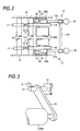
- Fig. 3 shows a second embodiment in which the projection portion 8 of the transmission member 7 is not disposed in the first press lever 10 but is disposed in the rotary shaft 14 which is formed integral with the first press lever 10.
- the projection portion 9 is not disposed in the second press lever 11 either, but can be disposed in a rotary shaft 15 formed integral with the second press lever 11.
- the projection portions 8 and 9 may be disposed in the rotary shafts 14 and 15 as the transmission member 7 but also gears or the like may be mounted on both of the rotary shafts 14, 15 to thereby transmit the swinging movement of the first press roller 6a to the second press roller 6b.
- Fig. 4 and Fig. 5 show a third embodiment in which the first press lever 10 is operated using a cam mechanism.
- the lift-up lever 17 is mounted on the first press lever 10.
- the lift-up lever 17 is rotatably mounted on the frame 13 by the eccentric pin 23 of a cam 22 and, in the first press lever 10, there is formed a lift-up bar receive portion 24 which can be contacted with the cam 22 having an elliptic shape.
- the eccentric pin 23 is always held in its regular position and, in this position, the outer peripheral surface of the cam 22 is contacted with the lift-up bar receive portion 24.
- the cam 22 When the lift-up bar 17a is rotated counterclockwise in Fig. 4, the cam 22 is rotated about the eccentric pin 23 and thus, at a large lift position (an outer peripheral surface position greatly distant from the eccentric pin 23), lifts up the lift-up lever receive portion 24 and the first press lever 10 formed integral therewith to thereby separate the first press roller 6a from the surface roller 4.
- the first press lever 10 similarly to the above-mentioned embodiment, rotates the second press lever 11 clockwise through the engagement between pawl-shaped projection portions 8 and 9 to thereby separate the second press roller 6b from the surface roller 4.
- the cam 22 can also be replaced with a lever and a roller disposed on the leading end thereof. In the embodiments shown in Figs.
- Fig. 6 shows a fourth embodiment in which means for engaging the transmission member 7 is composed of a pair of gears 25 and 26 which can be engaged with each other.
- the lift-up lever 17 (lift-up bar 17a), first press lever 10 and gear 25 can be rotated integrally with each other about the rotary shaft 14.
- the gear 26 is meshingly engaged with the gear 25 and can be rotated about the rotary shaft 15 integrally with the second press lever 11.
- the gears 25 and 26 are used as an engaging portion and a portion to be engaged; and, gear teeth formed in the respective gears 25 and 26 provide two or more securing portions.
- the first press lever 10 and first press roller 6a are separated from the surface roller 4 and, in linking.with this, due to the meshing engagement between. the gears 25 and 26, the second press lever 11 and second press roller 6b are also separated from the surface roller 4.
- the gear 25 and first press lever 10 as well as the gear 26 and second press lever 11 may not be formed as separate parts, but the associated sets of gears and press levers may be formed as integral parts.
- the press rollers 6a and 6b are fixed in a state where they are separated from the surface roller 4, for example, there may be formed penetration holes in the first press lever 10 and second press lever 11; also, in the portions of the frame 13 that correspond to the penetration holes formed in the first and second press levers 10 and 11 in a state where the press rollers 6a and 6b are separated from the surface roller 4, there are also formed penetration holes; and, single securing pins may be penetrated through the above two penetration holes to thereby fix the press rollers 6a and 6b.
- Fig. 7 shows a fifth embodiment in which, in the embodiment shown in Fig. 1, in order to hold the winding roller 5, there is additionally disposed a third press roller 27, this third press roller 27 is supported by a third press lever 29, and, through the cooperative operation between a projection portion 30 serving as the transmission member 7 of the second press lever 11 and a projection portion 31 serving as the transmission member 7 of the third press lever 29, the third press lever 29 is shifted in the separating direction.
- the third press lever 29 is rotatably supported in its regular position by a rotary shaft 28 fixed to the frame 13.
- Fig. 8 shows a sixth embodiment in which, in the embodiment shown in the above-discussed figure 6, instead of the gears 25 and 26 serving as the transmission members 7, there are used projection-shaped and recess-shaped parts to be meshingly engageable with each other, that is, a projection-shaped part 33 and a recess-shaped part 34 to be engaged with the projection-shaped part 33.
- the proj ection-shaped part 33 can be rotated about the rotary shaft 14 integrally with the first press lever 10 and lift-up lever 17, whereas the recess-shaped part 34 can be rotated about the rotary shaft 15 integrally with the second press lever 11.
- the projection-shaped part 33 and recess-shaped part 34 are engaged with each other and, in case where the lift-up bar 17a is rotated counterclockwise, the first press lever 10 and first press roller 6a are respectively separated from the surface roller 4 and, in linking with this, the second press lever 11 and second press roller 6b are also separated from the surface roller 4.
- the projection-shaped part 33 and recess-shaped part 34 respectively serve as an engaging portion and a portion to be engaged, while a projection portion formed in the projection-shaped part 33 and a recess portion formed in the recess-shaped part 34 serve as securing portions respectively.
- the gears 25 and 26 shown in Fig. 6 as well as the projection-shaped part 33 and recess-shaped part 34 shown in Fig. 8 respectively serving as the transmission members 7 can also be applied to the embodiments respectively shown in Figs. 1, 4 and 7.
- the embodiment shown in Fig. 8 similarly to the embodiment shown in Fig.
- the press rollers 6a and 6b may be fixed in a state where they are separated from the surface roller 4.
- a press roller apparatus for a weaving machine including two or more press rollers disposed so as to be connectable with and separatable from a surface roller
- the press roller apparatus includes a transmission member for transmitting the movement of any one of the press rollers to the other press roller and the other press roller is separated from the surface roller in linking with the separating operation of the above-mentioned any one press roll.
- the other press roller connected with the present press roller through the transmission member can be separated simultaneously with the present press roller. Thanks to this, two or more press rollers can be separated from the surface roller by an easy method and in a short time, thereby being able to enhance the operation efficiency of the present press roller apparatus.
- the two or more press rollers are disposed so as to be swingable and the transmission member, in linking with the swinging movement of the above-mentioned any one press roller, swings the other press roller. Therefore, two or more press rollers can be separated from the surface roller using a simple mechanism.
- any one of the press rollers is swung by operating a lift-up lever and the other press roller is swung in linking with the swinging movement of the above-mentioned any one press roller.
- Claim 4 by rotating the lift-up lever while part of the lift-up lever is contacted with a press lever or a frame, the operator can separate the press roller from the surface roller simply by operating the lift-up lever.
- the lift-up lever is composed of a lift-up bar supported so as to be rotatable with respect to the press lever, a roller rotatably.mounted on the lift-up bar, and a fixed wall is fixed to the frame (13) at a position where it can be contacted with this roller. Thanks to this, the operation force of the lift-up bar can be reduced and the lift-up bar at its lift-up position can be stabilized.
- the transmission member is mounted on the rotary shaft of the press lever and is composed of elements which can be engaged with each other, the range of the rotation angle of the lift-up lever can be set arbitrarily.
Landscapes
- Engineering & Computer Science (AREA)
- Textile Engineering (AREA)
- Looms (AREA)
- Treatment Of Fiber Materials (AREA)
- Spinning Or Twisting Of Yarns (AREA)
Abstract
Description
Claims (8)
- A press roller apparatus (2), for a weaving machine, comprising:a surface roller (4);two or more press rollers (6) disposed contactably with and separatably from the surface roller (4); anda transmission member (7) disposed between one press roller (6) and the other press roller (6), and transmitting the separating movement of one press roller (6) from the surface roller (4) to the other press roller (6) for separating the other press roller (6) from the surface roller (4).
- The press roller apparatus (2) according to claim 1,
further comprising two or more press levers (10, 11) supporting the respective press rollers (6) swingably to a frame (13), and
wherein the transmission member (7) includes: elements (8 · 9, 25. · 2 6, 33 · 34) engageable with each other, and transmiting the swinging movement of one press roller (6) to the other press roller (6) as the swinging movement of the other press roller (6) through their mutual engagement. - The press roller apparatus (2) according to claim 2,
wherein any one of the press levers (10, 11) can be swung by operating a lift-up lever (17). - The press roller apparatus (2) according to claim 2 or 3, further comprising a lift-up lever (17) mounted rotatably on one of the press levers (10, 11) and the frame (13); and
wherein the respective press rollers (6) are separated from the surface roller (4) when the lift-up lever (17) is rotated while contacting in part with the other of the press levers (10, 11) and the frame (13). - The press roller apparatus (2) according to claim 4, further comprising a fixed wall (20) fixed to the frame (13); and
wherein the lift-up lever (17) includes:a lift-up bar (17a) supported rotatably on the press lever (10); anda roller (19) mounted rotatably on the lift-up bar (17a), the fixed wall (20) is fixed at a position where it can.be contacted with the roller (19). - The press roller apparatus (2) according to claim 4 or 5, wherein the lift-up lever (17) includes:a lift-up bar (17a) supported rotatably on the frame (13) by an eccentric pin (23); anda cam (22) mounted so as to be rotatable integrally with the lift-up bar (17a); andwherein the press lever (10) includes a lift-up lever receive portion (24) fixed to the press lever (10) at a position contactable with the cam (22).
- The press roller apparatus (2) according to claim 3,4, 5 or 6, wherein the lift-up lever (17) includes a lift-up bar (17a) supported rotatably on the rotary shaft (14) of the press lever (10); and
wherein the transmission member (7) includes elements (25 · 26, 33 · 34) mounted on the rotary shaft (14, 15) of the press levers (10, 11), and the elements (25 · 26, 33 · 34) is engageable with each other. - The press roller apparatus (2) according to one of the preceding claims, further comprising a press roller for winding roller (27) disposed contactably with and separatably from a winding roller (5) ; and
wherein the movement transmitted from one press roller (6) to the other press roller (6) is further transmitted to the press roller for winding roller (27) by the transmission member (7); and
wherein when one press roller (6) is separated from the surface roller (4), the other press roller is separated from the surface roller (4), and the press roller for winding roller (27) is separated from the winding roller (5).
Applications Claiming Priority (2)
| Application Number | Priority Date | Filing Date | Title |
|---|---|---|---|
| JP2003174576A JP4089823B2 (en) | 2003-06-19 | 2003-06-19 | Loom press roll equipment |
| JP2003174576 | 2003-06-19 |
Publications (3)
| Publication Number | Publication Date |
|---|---|
| EP1489212A2 true EP1489212A2 (en) | 2004-12-22 |
| EP1489212A3 EP1489212A3 (en) | 2005-06-01 |
| EP1489212B1 EP1489212B1 (en) | 2007-06-27 |
Family
ID=33410977
Family Applications (1)
| Application Number | Title | Priority Date | Filing Date |
|---|---|---|---|
| EP04005039A Expired - Lifetime EP1489212B1 (en) | 2003-06-19 | 2004-03-03 | Press roller apparatus for weaving machine |
Country Status (4)
| Country | Link |
|---|---|
| EP (1) | EP1489212B1 (en) |
| JP (1) | JP4089823B2 (en) |
| CN (1) | CN100338283C (en) |
| DE (1) | DE602004007191T2 (en) |
Cited By (2)
| Publication number | Priority date | Publication date | Assignee | Title |
|---|---|---|---|---|
| DE102007051526B3 (en) * | 2007-10-29 | 2009-04-02 | Lindauer Dornier Gesellschaft Mit Beschränkter Haftung | Device for removing the web on a loom and loom with such a device |
| CN105220321A (en) * | 2015-10-27 | 2016-01-06 | 浙江万利纺织机械有限公司 | A kind of active drive type full-rolling type cloth cover induction system |
Families Citing this family (1)
| Publication number | Priority date | Publication date | Assignee | Title |
|---|---|---|---|---|
| JP4640094B2 (en) * | 2005-10-07 | 2011-03-02 | 株式会社豊田自動織機 | Press roller contact / separation device in loom |
Family Cites Families (9)
| Publication number | Priority date | Publication date | Assignee | Title |
|---|---|---|---|---|
| NL6905194A (en) * | 1969-04-02 | 1970-10-06 | ||
| BE904266A (en) * | 1986-02-24 | 1986-08-25 | Picanol Nv | CLOTH WRAPPING DEVICE FOR WEAVING MACHINES. |
| JPH0765854B2 (en) * | 1988-01-11 | 1995-07-19 | 株式会社神戸製鋼所 | Hot isostatic press |
| BE1001913A3 (en) * | 1988-05-03 | 1990-04-10 | Picanol Nv | Device for discharging the fabric of looms. |
| JP2868776B2 (en) * | 1988-12-28 | 1999-03-10 | 株式会社リコー | Recording medium mounting device |
| IT1266136B1 (en) * | 1993-02-18 | 1996-12-20 | Inter Patent Limited | DEVICE FOR THE ADVANCE OF THE FABRIC |
| JP3543444B2 (en) * | 1995-10-16 | 2004-07-14 | 株式会社豊田自動織機 | Press roller contacting / separating device for loom |
| JPH10110356A (en) * | 1996-10-06 | 1998-04-28 | Nissan Tecsys Kk | Winding press roller apparatus for weaving machine |
| JP3783427B2 (en) * | 1998-09-16 | 2006-06-07 | 株式会社豊田自動織機 | Weaving cloth take-up device in loom |
-
2003
- 2003-06-19 JP JP2003174576A patent/JP4089823B2/en not_active Expired - Fee Related
-
2004
- 2004-03-03 EP EP04005039A patent/EP1489212B1/en not_active Expired - Lifetime
- 2004-03-03 DE DE602004007191T patent/DE602004007191T2/en not_active Expired - Lifetime
- 2004-03-19 CN CNB2004100294707A patent/CN100338283C/en not_active Expired - Lifetime
Cited By (3)
| Publication number | Priority date | Publication date | Assignee | Title |
|---|---|---|---|---|
| DE102007051526B3 (en) * | 2007-10-29 | 2009-04-02 | Lindauer Dornier Gesellschaft Mit Beschränkter Haftung | Device for removing the web on a loom and loom with such a device |
| WO2009056093A1 (en) * | 2007-10-29 | 2009-05-07 | Lindauer Dornier Gesellschaft Mbh | Device for pulling a material web off a power loom and power loom comprising such a device |
| CN105220321A (en) * | 2015-10-27 | 2016-01-06 | 浙江万利纺织机械有限公司 | A kind of active drive type full-rolling type cloth cover induction system |
Also Published As
| Publication number | Publication date |
|---|---|
| JP4089823B2 (en) | 2008-05-28 |
| CN100338283C (en) | 2007-09-19 |
| DE602004007191T2 (en) | 2008-02-28 |
| CN1572940A (en) | 2005-02-02 |
| EP1489212B1 (en) | 2007-06-27 |
| JP2005009025A (en) | 2005-01-13 |
| EP1489212A3 (en) | 2005-06-01 |
| DE602004007191D1 (en) | 2007-08-09 |
Similar Documents
| Publication | Publication Date | Title |
|---|---|---|
| JP3372271B2 (en) | Cutting and folding device for web | |
| US6941093B2 (en) | Photoreceptive unit and transfer unit replacement system of printer | |
| EP0298696A1 (en) | Heddle transferring apparatus | |
| US4147105A (en) | Protective device for a perfector printing press | |
| EP1489212B1 (en) | Press roller apparatus for weaving machine | |
| EP0396220A2 (en) | Device for the attachment of a flexible printing form to a printing cylinder | |
| EP1475336A1 (en) | Folding apparatus of rotary press | |
| JP3858789B2 (en) | Door lock device for construction machinery | |
| JPH08207237A (en) | Printing unit chenge-over device | |
| JP3848060B2 (en) | Sheet post-processing device | |
| JPH0345739A (en) | Loom with pivotally-driving device for shaft-connecting part | |
| EP1245517B1 (en) | Paper roll driving apparatus | |
| US4133263A (en) | Sheet-turning drum for printing machines convertible from printing on one side of a sheet to printing on both sides of a sheet and vice versa | |
| US3618939A (en) | Mechanism for orienting paper sheets | |
| US4699181A (en) | Rotary dobby | |
| JPH0679765U (en) | Leveling device for shedding device in loom | |
| JPS5930930A (en) | Opening apparatus in loom | |
| JPH0368135B2 (en) | ||
| JP2947285B2 (en) | Sheet transfer mechanism in offset printing press | |
| JP4091191B2 (en) | Cam moving device in printing press | |
| JPH0471710B2 (en) | ||
| CN1944733B (en) | Press roller approach/apart device for weaving machine | |
| JP2500967Y2 (en) | Interlocking mechanism between yarn end treatment yarn gear and cover body | |
| JP3738769B2 (en) | Card support frame lock mechanism of dobby machine | |
| DE4428796C2 (en) | Front loading washer or washer dryer with a swinging inner door |
Legal Events
| Date | Code | Title | Description |
|---|---|---|---|
| PUAI | Public reference made under article 153(3) epc to a published international application that has entered the european phase |
Free format text: ORIGINAL CODE: 0009012 |
|
| AK | Designated contracting states |
Kind code of ref document: A2 Designated state(s): AT BE BG CH CY CZ DE DK EE ES FI FR GB GR HU IE IT LI LU MC NL PL PT RO SE SI SK TR |
|
| AX | Request for extension of the european patent |
Extension state: AL LT LV MK |
|
| PUAL | Search report despatched |
Free format text: ORIGINAL CODE: 0009013 |
|
| AK | Designated contracting states |
Kind code of ref document: A3 Designated state(s): AT BE BG CH CY CZ DE DK EE ES FI FR GB GR HU IE IT LI LU MC NL PL PT RO SE SI SK TR |
|
| AX | Request for extension of the european patent |
Extension state: AL LT LV MK |
|
| 17P | Request for examination filed |
Effective date: 20050728 |
|
| AKX | Designation fees paid |
Designated state(s): BE CH DE IT LI |
|
| GRAP | Despatch of communication of intention to grant a patent |
Free format text: ORIGINAL CODE: EPIDOSNIGR1 |
|
| GRAS | Grant fee paid |
Free format text: ORIGINAL CODE: EPIDOSNIGR3 |
|
| GRAA | (expected) grant |
Free format text: ORIGINAL CODE: 0009210 |
|
| AK | Designated contracting states |
Kind code of ref document: B1 Designated state(s): BE CH DE IT LI |
|
| REG | Reference to a national code |
Ref country code: CH Ref legal event code: NV Representative=s name: BOVARD AG PATENTANWAELTE Ref country code: CH Ref legal event code: EP |
|
| REF | Corresponds to: |
Ref document number: 602004007191 Country of ref document: DE Date of ref document: 20070809 Kind code of ref document: P |
|
| PLBE | No opposition filed within time limit |
Free format text: ORIGINAL CODE: 0009261 |
|
| STAA | Information on the status of an ep patent application or granted ep patent |
Free format text: STATUS: NO OPPOSITION FILED WITHIN TIME LIMIT |
|
| 26N | No opposition filed |
Effective date: 20080328 |
|
| REG | Reference to a national code |
Ref country code: CH Ref legal event code: PFA Owner name: TSUDAKOMA KOGYO KABUSHIKI KAISHA Free format text: TSUDAKOMA KOGYO KABUSHIKI KAISHA#18-18, NOMACHI 5-CHOME#KANAZAWA-SHI, ISHIKAWA-KEN 921-8650 (JP) -TRANSFER TO- TSUDAKOMA KOGYO KABUSHIKI KAISHA#18-18, NOMACHI 5-CHOME#KANAZAWA-SHI, ISHIKAWA-KEN 921-8650 (JP) |
|
| PGFP | Annual fee paid to national office [announced via postgrant information from national office to epo] |
Ref country code: CH Payment date: 20130312 Year of fee payment: 10 |
|
| REG | Reference to a national code |
Ref country code: CH Ref legal event code: PL |
|
| PG25 | Lapsed in a contracting state [announced via postgrant information from national office to epo] |
Ref country code: LI Free format text: LAPSE BECAUSE OF NON-PAYMENT OF DUE FEES Effective date: 20140331 Ref country code: CH Free format text: LAPSE BECAUSE OF NON-PAYMENT OF DUE FEES Effective date: 20140331 |
|
| PGFP | Annual fee paid to national office [announced via postgrant information from national office to epo] |
Ref country code: DE Payment date: 20170228 Year of fee payment: 14 |
|
| PGFP | Annual fee paid to national office [announced via postgrant information from national office to epo] |
Ref country code: BE Payment date: 20170213 Year of fee payment: 14 |
|
| PGFP | Annual fee paid to national office [announced via postgrant information from national office to epo] |
Ref country code: IT Payment date: 20170320 Year of fee payment: 14 |
|
| REG | Reference to a national code |
Ref country code: DE Ref legal event code: R119 Ref document number: 602004007191 Country of ref document: DE |
|
| REG | Reference to a national code |
Ref country code: BE Ref legal event code: MM Effective date: 20180331 |
|
| PG25 | Lapsed in a contracting state [announced via postgrant information from national office to epo] |
Ref country code: DE Free format text: LAPSE BECAUSE OF NON-PAYMENT OF DUE FEES Effective date: 20181002 |
|
| PG25 | Lapsed in a contracting state [announced via postgrant information from national office to epo] |
Ref country code: IT Free format text: LAPSE BECAUSE OF NON-PAYMENT OF DUE FEES Effective date: 20180303 Ref country code: BE Free format text: LAPSE BECAUSE OF NON-PAYMENT OF DUE FEES Effective date: 20180331 |