EP1488955A2 - Lighting device for vehicles - Google Patents
Lighting device for vehicles Download PDFInfo
- Publication number
- EP1488955A2 EP1488955A2 EP04014106A EP04014106A EP1488955A2 EP 1488955 A2 EP1488955 A2 EP 1488955A2 EP 04014106 A EP04014106 A EP 04014106A EP 04014106 A EP04014106 A EP 04014106A EP 1488955 A2 EP1488955 A2 EP 1488955A2
- Authority
- EP
- European Patent Office
- Prior art keywords
- side additional
- lamp
- vehicle
- steering
- driver circuit
- Prior art date
- Legal status (The legal status is an assumption and is not a legal conclusion. Google has not performed a legal analysis and makes no representation as to the accuracy of the status listed.)
- Granted
Links
Images


Classifications
-
- B—PERFORMING OPERATIONS; TRANSPORTING
- B60—VEHICLES IN GENERAL
- B60Q—ARRANGEMENT OF SIGNALLING OR LIGHTING DEVICES, THE MOUNTING OR SUPPORTING THEREOF OR CIRCUITS THEREFOR, FOR VEHICLES IN GENERAL
- B60Q1/00—Arrangement of optical signalling or lighting devices, the mounting or supporting thereof or circuits therefor
- B60Q1/02—Arrangement of optical signalling or lighting devices, the mounting or supporting thereof or circuits therefor the devices being primarily intended to illuminate the way ahead or to illuminate other areas of way or environments
- B60Q1/04—Arrangement of optical signalling or lighting devices, the mounting or supporting thereof or circuits therefor the devices being primarily intended to illuminate the way ahead or to illuminate other areas of way or environments the devices being headlights
- B60Q1/06—Arrangement of optical signalling or lighting devices, the mounting or supporting thereof or circuits therefor the devices being primarily intended to illuminate the way ahead or to illuminate other areas of way or environments the devices being headlights adjustable, e.g. remotely-controlled from inside vehicle
- B60Q1/08—Arrangement of optical signalling or lighting devices, the mounting or supporting thereof or circuits therefor the devices being primarily intended to illuminate the way ahead or to illuminate other areas of way or environments the devices being headlights adjustable, e.g. remotely-controlled from inside vehicle automatically
- B60Q1/12—Arrangement of optical signalling or lighting devices, the mounting or supporting thereof or circuits therefor the devices being primarily intended to illuminate the way ahead or to illuminate other areas of way or environments the devices being headlights adjustable, e.g. remotely-controlled from inside vehicle automatically due to steering position
-
- B—PERFORMING OPERATIONS; TRANSPORTING
- B60—VEHICLES IN GENERAL
- B60Q—ARRANGEMENT OF SIGNALLING OR LIGHTING DEVICES, THE MOUNTING OR SUPPORTING THEREOF OR CIRCUITS THEREFOR, FOR VEHICLES IN GENERAL
- B60Q1/00—Arrangement of optical signalling or lighting devices, the mounting or supporting thereof or circuits therefor
- B60Q1/02—Arrangement of optical signalling or lighting devices, the mounting or supporting thereof or circuits therefor the devices being primarily intended to illuminate the way ahead or to illuminate other areas of way or environments
- B60Q1/04—Arrangement of optical signalling or lighting devices, the mounting or supporting thereof or circuits therefor the devices being primarily intended to illuminate the way ahead or to illuminate other areas of way or environments the devices being headlights
- B60Q1/18—Arrangement of optical signalling or lighting devices, the mounting or supporting thereof or circuits therefor the devices being primarily intended to illuminate the way ahead or to illuminate other areas of way or environments the devices being headlights being additional front lights
-
- B—PERFORMING OPERATIONS; TRANSPORTING
- B60—VEHICLES IN GENERAL
- B60Q—ARRANGEMENT OF SIGNALLING OR LIGHTING DEVICES, THE MOUNTING OR SUPPORTING THEREOF OR CIRCUITS THEREFOR, FOR VEHICLES IN GENERAL
- B60Q2300/00—Indexing codes for automatically adjustable headlamps or automatically dimmable headlamps
- B60Q2300/10—Indexing codes relating to particular vehicle conditions
- B60Q2300/11—Linear movements of the vehicle
- B60Q2300/112—Vehicle speed
-
- B—PERFORMING OPERATIONS; TRANSPORTING
- B60—VEHICLES IN GENERAL
- B60Q—ARRANGEMENT OF SIGNALLING OR LIGHTING DEVICES, THE MOUNTING OR SUPPORTING THEREOF OR CIRCUITS THEREFOR, FOR VEHICLES IN GENERAL
- B60Q2300/00—Indexing codes for automatically adjustable headlamps or automatically dimmable headlamps
- B60Q2300/10—Indexing codes relating to particular vehicle conditions
- B60Q2300/12—Steering parameters
- B60Q2300/122—Steering angle
-
- B—PERFORMING OPERATIONS; TRANSPORTING
- B60—VEHICLES IN GENERAL
- B60Q—ARRANGEMENT OF SIGNALLING OR LIGHTING DEVICES, THE MOUNTING OR SUPPORTING THEREOF OR CIRCUITS THEREFOR, FOR VEHICLES IN GENERAL
- B60Q2300/00—Indexing codes for automatically adjustable headlamps or automatically dimmable headlamps
- B60Q2300/10—Indexing codes relating to particular vehicle conditions
- B60Q2300/12—Steering parameters
- B60Q2300/128—Steering dead zone
-
- B—PERFORMING OPERATIONS; TRANSPORTING
- B60—VEHICLES IN GENERAL
- B60Q—ARRANGEMENT OF SIGNALLING OR LIGHTING DEVICES, THE MOUNTING OR SUPPORTING THEREOF OR CIRCUITS THEREFOR, FOR VEHICLES IN GENERAL
- B60Q2300/00—Indexing codes for automatically adjustable headlamps or automatically dimmable headlamps
- B60Q2300/10—Indexing codes relating to particular vehicle conditions
- B60Q2300/14—Other vehicle conditions
- B60Q2300/144—Rearward ratio actuation
Definitions
- the present invention relates to a vehicle lighting device. More specifically, this invention relates to turning on and off of lamps that are mounted on a vehicle in addition to the head lights.
- road surface and the like includes any one of a surface of a road (hereinafter, “road surface”) on which a vehicle is running, a person on the road surface, and an object in a view of the driver of the vehicle.
- road surface a surface of a road
- object for example, cars on the road surface, road signs, and building around the road.
- Vehicle lighting devices are sometimes mounted, in addition to other lights such as head lights, on right and left sides of the front part of a vehicle.
- a conventional vehicle lighting device has been disclosed, for example, Japanese Patent Application Laid Open No. 2001-138802.
- the vehicle lighting device disclosed in this literature includes left- and right-side steer lamps (3a, 3b). These steer lamps turn on/off through switching on/off of a lighting switch, adjust a range to be illuminated based on a steering angle, turn off when the vehicle backs up, and turn on when the vehicle shifts to a normal running state.
- the steer lamps (3a, 3b) concurrently turn on or off. As a result, power is consumed unnecessarily.
- a vehicle lighting device is mounted on a vehicle.
- the vehicle lighting device includes at least one left-side additional lamp that is mounted at a first place on a front part of the vehicle; at least one right-side additional lamp that is mounted on a second place on the front part of the vehicle; a steering sensor that detects a steering angle and a steering direction of steering of the vehicle and outputs a steering signal that represents the steering angle and the steering direction detected; a reverse sensor that detects whether a shift lever of the vehicle is in a reverse position and outputs a reverse signal when the shift lever is in the reverse position; a left-side additional-lamp driver circuit that drives the left-side additional lamp; a right-side additional-lamp driver circuit that drives with the right-side additional lamp; and a control device.
- the control device controls the left-side additional-lamp driver circuit so as to turn on the left-side additional lamp when the steering signal indicates that the vehicle is turning to left, and controls the right-side additional-lamp driver circuit so as to turn on the right-side additional lamp when the steering signal indicates that the vehicle is turning to right, and controls the left-side additional-lamp driver circuit so as to turn off the left-side additional lamp and controls the right-side additional-lamp driver circuit so as to turn off the right-side additional lamp when the reverse sensor outputs the reverse signal.
- a vehicle lighting device is mounted on a vehicle.
- the vehicle lighting device includes at least one left-side additional lamp that is mounted at a first place on a front part of the vehicle; at least one right-side additional lamp that is mounted on a second place on the front part of the vehicle; a steering sensor that detects a steering angle and a steering direction of steering of the vehicle and outputs a steering signal that represents the steering angle and the steering direction detected; a reverse sensor that detects whether a shift lever of the vehicle is in a reverse position and outputs a reverse signal when the shift lever is in the reverse position; a left-side additional-lamp driver circuit that drives the left-side additional lamp; a right-side additional-lamp driver circuit that drives with the right-side additional lamp; and a control device.
- the control device controls the left-side additional-lamp driver circuit so as to turn on the left-side additional lamp when the steering signal indicates that the vehicle is turning to left, and controls the right-side additional-lamp driver circuit so as to turn on the right-side additional lamp when the steering signal indicates that the vehicle is turning to right, controls the left-side additional-lamp driver circuit so as to turn on the left-side additional lamp and controls the right-side additional-lamp driver circuit so as to turn off the right-side additional lamp when the reverse sensor outputs the reverse signal while the steering signal indicates that the vehicle is turning to right, and controls the right-side additional-lamp driver circuit so as to turn on the right-side additional lamp and controls the left-side additional-lamp driver circuit so as to turn off the left-side additional lamp when the reverse sensor outputs the reverse signal while the steering signal indicates that the vehicle is turning to left.
- Fig. 1 to Fig. 4 relate a vehicle lighting - device according to a first embodiment of the present invention.
- Fig. 5, Fig. 6A, and Fig. 6B relate to a vehicle lighting device according to a second embodiment of the present invention.
- the vehicle lighting device relates to a lighting system that includes a left-side additional lamp and a right-side additional lamp.
- the left-side additional lamp and the right-side additional lamp are turned on and off separately and in synchronization with the steering of a steering wheel.
- the vehicle lighting device includes a left-side additional lamp 1L, a right-side additional lamp 1R, a steering angle sensor 2, a headlamp switch 3, a reverse sensor 4, a speed sensor 5, a control device 6 (control circuit and ECU-electronic control unit), a left-side additional-lamp driver circuit 13L, and a right-side additional-lamp driver circuit 13R.
- the left-side additional lamp 1L and the right-side additional lamp 1R are mounted on the left side and the right side of the front part of a vehicle 7, respectively. As shown in Fig. 3A, Fig. 3B, and Fig. 4, left-side headlamp 8L and a right-side headlamp 8R are mounted on the left side and the right side of the front part of the vehicle 7, respectively.
- the left-side headlamp 8L and the right-side headlamp 8R illuminate a road surface and the like with lights having predetermined light distribution patterns PL1 and PR1, respectively.
- the left-side additional lamp 1L is provided near and on the left-side of the left-side headlamp 8L, and the right-side additional lamp 1R is provided near and on the right-side of the right-side headlamp 8R.
- the left-side additional lamp 1L illuminates the road surface and the like with light having a predetermined light distribution pattern PL2, and the right-side additional lamp 1R illuminates the road surface and the like with light having a predetermined light distribution pattern PR2.
- the light having the predetermined light distribution pattern PL2 is illuminated outward the left side of the light distribution pattern PL1 from the left-side headlamp 8L.
- the light having the predetermined light distribution pattern PR2 is illuminated outward the right side of the light distribution pattern PR1 from the right-side headlamp 8R.
- the left-side additional lamp 1L and the right-side additional lamp 1R are connected to an ignition switch 9 and a battery 10 through the control device 6.
- the left-side headlamp 8L and the right-side headlamp 8R are also connected to the ignition switch 9 and the battery 10 through the control device 6, although the connection is not shown in Fig. 1.
- the left-side additional lamp 1L and the right-side additional lamp 1R may be a fixing type, or may be a rotary type in which an optical axis is made to rotate to the right and the left in synchronization with the steering of a steering wheel.
- the steering angle sensor 2 detects a rotation angle and a direction of rotation of the steering wheel (not shown) of a vehicle on which the vehicle lighting device is mounted.
- the steering angle sensor 2 outputs a steering angle signal that represents the detected rotation angle and the direction of rotation.
- the speed sensor 5 detects a speed of the vehicle and outputs a speed signal that represents the detected speed.
- the driver operates the headlamp switch 3 to turn on and off the left-side and the right-side headlamps 8L and 8R.
- the headlamp switch 3 outputs an on-signal when it is in an on-state and outputs an off-signal when it is in an off-state.
- a high-level voltage signal may be output as the on-signal and a low-level signal can be output as the off-signal.
- the headlamp switch 3 may also be used to switch the headlamps 8L and 8R between a low beam (meeting beam) position and a high beam (main beam) position.
- the reverse sensor 4 detects a reverse position out of the shift positions of a shift lever (not shown) and outputs a reverse signal. That is, the reverse sensor 4 outputs the reverse signal when the shift lever is operated to the reverse position.
- the control device 6 includes an interface circuit 11 that serves as an external signal input device connected with the steering angle sensor 2, the headlamp switch 3, the reverse sensor 4, and the speed sensor 5.
- the control device 6 also includes a central processing unit-CPU 12 (processing controller), the left-side additional-lamp driver circuit 13L connected with the left-side additional lamp 1L (left-side additional lamp driver), the right-side additional-lamp driver circuit 13R connected with the right-side additional lamp 1R (right-side additional lamp driver), and a power circuit 14.
- a relay or a semiconductor switch a field-effect transistor (FET) and a transistor
- the steering angle signal of the steering angle sensor 2; the on-signal and the off-signal of the headlamp switch 3, the reverse signal of the reverse sensor 4, and the speed signal of the speed sensor 5 are input to the interface circuit 11.
- the central processing unit-CPU 12 determines whether the left-side additional lamp 1L and the right-side additional lamp 1R are to be turned on and off based on the signals input. Based on the results of determination, the central processing unit-CPU 12 performs the processes of turning on and off the left-side additional lamp 1L and the right-side additional lamp 1R through the left-side additional-lamp driver circuit 13L and the right-side additional-lamp driver circuit 13R, respectively.
- control device 6 performs the processes of turning on the left-side additional lamp 1L and the right-side additional lamp 1R separately and turning them off separately, based on the steering angle signal.
- the control device 6 performs the process of turning off the left-side additional lamp 1L and the right-side additional lamp 1R.
- the control device 6 is a computer mounted on the vehicle.
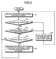
- Fig. 2 is a flowchart of a process procedure performed by the control device 6.
- the control device 6 is started.
- the steering angle sensor 2 detects a steering angle and outputs a steering angle signal.
- the speed sensor 5 detects a speed of the vehicle and outputs a speed signal.
- the control device 6 receives the steering angle signal and the speed signal (step S1). The control device 6 then determines whether the headlamp switch 3 is on or off based on an on-signal and off-signal output from the headlamp switch 3 (step S-2). When the headlamp switch 3 is off, the control device 6 performs the process of turning off the left-side additional lamp 1L and the right-side additional lamp 1R (step S6), and then the process returns to step S1.
- step S3 When the headlamp switch 3 is on, i.e., when the left-side and the right-side headlamps 8L and 8R are on, the control device 6 determines whether a reverse signal has been received (step S3). When the reverse signal has not been received, the control device 6 determines, from the steering signal, whether the steering angle is zero (center) (S4). When the steering angle is zero, i.e., when the vehicle is running straight, the process returns to step S1.
- step S5 the control device 6 performs the processes of turning on the left-side additional lamp 1L and the right-side additional lamp 1R separately and turning them off separately, in synchronization with the steering of the steering wheel (step S5), and then the process returns to step S1.
- the steering angle sensor 2 outputs a steering angle signal that represents that the vehicle is turning toward right, and the control device 6 performs the process of turning on the right-side additional lamp 1R.
- the right-side additional lamp 1R is turned on so that the road surface and the like is illuminated with a light having the light distribution pattern PR2.
- the light distribution pattern PR2 is provided rightward the predetermined light distribution patterns PL1 and PR1 by the left-side and the right-side headlamps 8L and 8R.
- the steering angle sensor 2 outputs a steering angle signal that represents that the vehicle is turning toward right, and the control device 6 performs the process of turning on the left-side additional lamp 1L.
- the left-side additional lamp 1L is turned on so that the road surface and the like is illuminated with a light having the light distribution pattern PL2.
- the light distribution pattern PL2 is provided leftward the predetermined light distribution patterns PL1 and PR1 by the left-side and the right-side headlamps 8L and 8R.
- the vehicle lighting device separately turns on and off the left-side additional lamp 1L and the right-side additional lamp 1R in synchronization with steering of the steering wheel.
- step S3 when the reverse signal has been received, in other words, when the vehicle 7 is backing up, the control device 6 performs the process of turning off the left-side additional lamp 1L or the right-side additional lamp 1R, which is on (step S6), and the process returns to step S1.
- the control device 6 when the driver is backing up the vehicle 7 and is about to put it into a garage 15 while turning the steering wheel to the right, the control device 6 performs the process of turning off the right-side additional lamp 1R through the right-side additional-lamp driver circuit 13R upon reception of the reverse signal from the reverse sensor 4. Conversely, when the driver is backing up the vehicle 7 and is about to put it into the garage 15 while turning the steering wheel to the left, the control device 6 performs the process of turning off the left-side additional lamp 1L through the left-side additional-lamp driver circuit 13L upon reception of the reverse signal. As a result, when the vehicle 7 is backing up, the left-side additional lamp 1L and the right-side additional lamp 1R are off. It is noted that when the vehicle 7 is backing up, the left-side headlamp 8L and the right-side headlamp 8R may be turned off.
- the left-side additional lamp 1L and the right-side additional lamp 1R can be turned on separately and turned off separately in synchronization with the steering of the steering wheel. Therefore, the vehicle lighting device according to the first embodiment can be operated at lesser power as compared with the conventional vehicle lighting device (3a, 3b).
- the left-side additional lamp 1L and the right-side additional lamp 1R are turned off when the vehicle 7 backs up. Therefore, such annoyance as explained below is eliminated.
- the annoyance is such that the left-side additional lamp 1L and the right-side additional lamp 1R repeatedly turn on or off in synchronization with the steering of the steering wheel while the vehicle 7 is backing up. Particularly, if the lamp is lit to illuminate a range at which the driver does not look, the driver may be annoyed with the illumination. Therefore, the elimination allows safety to be assured while the vehicle 7 is backing up.
- the left-side additional lamp 1L and the right-side additional lamp 1R are a kind of auxiliary lamps, and therefore, even if they are turned off upon backing up of the vehicle 7, there is no particular problem on traffic safety to occur. Furthermore, it is possible to reduce power consumption as compared with the conventional vehicle lighting device that concurrently turns on left-side and right-side auxiliary lamps (5a, 5b) when concurrently turning off the left-side and right-side steer lamps (3a, 3b).
- the left-side additional lamp 1L is connected to the left-side additional-lamp driver circuit 13L
- the right-side additional lamp 1R is connected to the right-side additional-lamp driver circuit 13R. Therefore, it is possible to reliably control the processes of turning on the left-side additional lamp 1L and the right-side additional lamp 1R separately and turning them off separately.
- the vehicle lighting device is configured with the existing control device 6 (control circuit and ECU-electronic control unit) and the central processing unit-CPU 12 (processing controller) with minor changes provided thereon, which allows manufacturing costs to be reduced.
- control device 6 control circuit and ECU-electronic control unit
- CPU 12 processing controller
- the control device 6 when receiving the reverse signal from the reverse sensor 4 and the steering of the steering wheel has the predetermined angle or more, the control device 6 may be configured to perform the process of turning off the left-side additional lamp 1L and the right-side additional lamp 1R through the left-side additional-lamp driver circuit 13L and the right-side additional-lamp driver circuit 13R, respectively.
- the "predetermined angle or more” is set to, for example, a steering angle in which the basic steering of the steering wheel is added to an idle angle of the steering wheel with respect to the neutral position of the steering wheel. If the control device 6 is thus configured, it is possible to perform the process of turning off the left-side additional lamp 1L and the right-side additional lamp 1R according to how the vehicle 7 is backing up.
- FIG. 5 A vehicle lighting device according to a second embodiment of the present invention is explained below with reference to Fig. 5, Fig. 6A, and Fig. 6B.
- the same reference signs as these of Fig. 1 to Fig. 4 indicate the same components or procedures.
- the control device 6 functions in a different manner from that in the vehicle lighting device according to the first embodiment.
- the control device 6 performs the processes of turning on the left-side additional lamp 1L and the right-side additional lamp 1R separately and turning them off separately, based on the steering angle signal from the steering angle sensor 2.
- the control device 6 performs the process of turning on either one of the additional lamps on the opposite side to the steering direction and performs the process of turning off the other one on the side of the steering direction upon reception of the reverse signal from the reverse sensor 4.
- step S3 when the reverse signal has been received, in other words, when the vehicle 7 is backing up, the control device 6 determines whether the steering to the right has a predetermined angle or more (step S7). When the steering to the right has the predetermined angle or more, the control device 6 performs the process of turning on the left-side additional lamp 1L and performs the process of turning off the right-side additional lamp 1R (step S8), and then the process returns to step S1.
- the control device 6 when the driver is backing up the vehicle 7 while turning the steering wheel to the right, the control device 6 performs the process of turning on the left-side additional lamp 1L and performs the process of turning off the right-side additional lamp 1R based on the steering angle signal and the reverse signal.
- the left-side additional lamp 1L when the vehicle 7 is backing up rightward, the left-side additional lamp 1L is turned on and the right-side additional lamp 1R is turned off.
- the left-side additional lamp 1L on the opposite side to the steering direction lights up. Therefore, it is possible to illuminate an area on the side of arrow L to which the vehicle 7 turns, with light having the predetermined light distribution pattern PL2.
- step S7 when the steering to the right has the predetermined angle or less, the control device 6 determines whether the steering to the left has the predetermined angle or more (step S9). When the steering to the left has the predetermined angle or more, the control device 6 performs the process of turning on the right-side additional lamp 1R and performs the process of turning off the left-side additional lamp 1L (step S10), and then the process returns to step S1.
- the control device 6 when the driver is backing up the vehicle 7 while turning the steering wheel to the left, the control device 6 performs the process of turning on the right-side additional lamp 1R and performs the process of turning off the left-side additional lamp 1L based on the steering angle signal and the reverse signal.
- the right-side additional lamp 1R when the vehicle 7 is backing up leftward, the right-side additional lamp 1R is turned on and the left-side additional lamp 1L is turned off.
- the right-side additional lamp 1R on the opposite side to the steering direction lights up. Therefore, it is possible to illuminate an area on the side of arrow R to which the vehicle 7 turns, with light having the predetermined light distribution pattern PR2.
- step S9 when the steering to the left has the predetermined angle or less, the control device 6 proceeds to step S6, and then returns to S1.
- the left-side headlamp 8L and the right-side headlamp 8R may be previously turned off.
- the vehicle lighting device according to the second embodiment can reduce power consumption as compared with the conventional vehicle lighting device that concurrently turns on or off the left-side and right-side steer lamps (3a, 3b) or that concurrently turns on the left-side and right-side auxiliary lamps (5a, 5b) when concurrently turning off the left-side and right-side steer lamps (3a, 3b).
- the left-side additional lamp 1L is connected to the left-side additional-lamp driver circuit 13L
- the right-side additional lamp 1R is connected to the right-side additional-lamp driver circuit 13R. Therefore, it is possible to reliably control the processes of turning on the left-side additional lamp 1L and the right-side additional lamp 1R separately and turning them off separately.
- the additional lamp on the opposite side to the steering direction lights up when the vehicle 7 is backing up.
- the additional lamp on the opposite side to the steering direction lights up when the vehicle 7 is backing up.
- the control device 6 when the steering of the steering wheel has the predetermined angle or more, the control device 6 performs the process of turning on either one of the additional lamps on the opposite side to the steering direction and performs the process of turning off the other one on the side of the steering direction. Therefore, the vehicle lighting device according to the second embodiment can perform the process of turning off the left-side additional lamp 1L and the right-side additional lamp 1R according to how the vehicle 7 is backing up.
- the "predetermined angle or more" is set to, for example, a steering angle in which the basic steering of the steering wheel is added to an idle angle of the steering wheel with respect to the neutral position of the steering wheel.
Landscapes
- Engineering & Computer Science (AREA)
- Mechanical Engineering (AREA)
- Lighting Device Outwards From Vehicle And Optical Signal (AREA)
Abstract
Description
For example, cars on the road surface, road signs, and building around the road.
Claims (4)
- A vehicle lighting device mounted on a vehicle (7), comprising:at least one left-side additional lamp (1L) that is mounted at a first place on a front part of the vehicle (7);at least one right-side additional lamp (1R) that is mounted on a second place on the front part of the vehicle (7);a steering sensor (2) that detects a steering angle and a steering direction of steering of the vehicle (7) and outputs a steering signal that represents the steering angle and the steering direction detected;a reverse sensor (4) that detects whether a shift lever of the vehicle (7) is in a reverse position and outputs a reverse signal when the shift lever is in the reverse position;a left-side additional-lamp driver circuit (13L) that drives the left-side additional lamp (1L);a right-side additional-lamp driver circuit (13R) that drives with the right-side additional lamp (1R); anda control device (6) that
controls the left-side additional-lamp driver circuit (13L) so as to turn on the left-side additional lamp (1L) when the steering signal indicates that the vehicle is turning to left, and controls the right-side additional-lamp driver circuit (13R) so as to turn on the right-side additional lamp (1R) when the steering signal indicates that the vehicle is turning to right, and
controls the left-side additional-lamp driver circuit (13L) so as to turn off the left-side additional lamp (1L) and controls the right-side additional-lamp driver circuit (13R) so as to turn off the right-side additional lamp (1R) when the reverse sensor (4) outputs the reverse signal. - The vehicle lighting device according to claim 1, wherein when the reverse sensor (4) outputs the reverse signal and the steering angle represented by the steering signal is equal to more that a predetermined angle, the control device (6) turns off the left-side additional lamp (1L) and the right-side additional lamp (1R).
- A vehicle lighting device mounted on a vehicle (7), comprising:at least one left-side additional lamp (1L) that is mounted at a first place on a front part of the vehicle (7);at least one right-side additional lamp (1R) that is mounted on a second place on the front part of the vehicle (7);a steering sensor (2) that detects a steering angle and a steering direction of steering of the vehicle (7) and outputs a steering signal that represents the steering angle and the steering direction detected;a reverse sensor (4) that detects whether a shift lever of the vehicle (7) is in a reverse position and outputs a reverse signal when the shift lever is in the reverse position;a left-side additional-lamp driver circuit (13L) that drives the left-side additional lamp (1L);a right-side additional-lamp driver circuit (13R) that drives with the right-side additional lamp (1R); anda control device (6) that
controls the left-side additional-lamp driver circuit (13L) so as to turn on the left-side additional lamp (1L) when the steering signal indicates that the vehicle is turning to left, and controls the right-side additional-lamp driver circuit (13R) so as to turn on the right-side additional lamp (1R) when the steering signal indicates that the vehicle is turning to right,
controls the left-side additional-lamp driver circuit (13L) so as to turn on the left-side additional lamp (1L) and controls the right-side additional-lamp driver circuit (13R) so as to turn off the right-side additional lamp (1R) when the reverse sensor (4) outputs the reverse signal while the steering signal indicates that the vehicle is turning to right, and
controls the right-side additional-lamp driver circuit (13R) so as to turn on the right-side additional lamp (1R) and controls the left-side additional-lamp driver circuit (13L) so as to turn off the left-side additional lamp (1L) when the reverse sensor (4) outputs the reverse signal while the steering signal indicates that the vehicle is turning to left. - The vehicle lighting device according to claim 3, wherein when the reverse sensor (4) outputs the reverse signal and the steering angle represented in the steering signal is equal to or more than a predetermined angle, the control device (6) turns on either one of the left-side additional lamp (1L) and the right-side additional lamp (1R) on the opposite side to the steering direction represented in the steering angle, and performs the process of turning off the other one on the side of the steering direction, wherein the processes are performed through the left-side additional-lamp driver circuit (13L) and the right-side additional-lamp driver circuit (13R).
Applications Claiming Priority (2)
| Application Number | Priority Date | Filing Date | Title |
|---|---|---|---|
| JP2003175336A JP2005008076A (en) | 2003-06-19 | 2003-06-19 | Vehicle lighting |
| JP2003175336 | 2003-06-19 |
Publications (3)
| Publication Number | Publication Date |
|---|---|
| EP1488955A2 true EP1488955A2 (en) | 2004-12-22 |
| EP1488955A3 EP1488955A3 (en) | 2005-09-14 |
| EP1488955B1 EP1488955B1 (en) | 2007-04-25 |
Family
ID=33410995
Family Applications (1)
| Application Number | Title | Priority Date | Filing Date |
|---|---|---|---|
| EP04014106A Expired - Lifetime EP1488955B1 (en) | 2003-06-19 | 2004-06-16 | Lighting device for vehicles |
Country Status (3)
| Country | Link |
|---|---|
| EP (1) | EP1488955B1 (en) |
| JP (1) | JP2005008076A (en) |
| DE (1) | DE602004006052T2 (en) |
Cited By (2)
| Publication number | Priority date | Publication date | Assignee | Title |
|---|---|---|---|---|
| FR2942433A1 (en) * | 2009-02-25 | 2010-08-27 | Peugeot Citroen Automobiles Sa | Control device for controlling light sources of e.g. front headlamp, of motor vehicle e.g. car, has control module defining ignition control laws of light sources based on thresholds of steering lock angle of steering wheel of motor vehicle |
| WO2022038117A1 (en) * | 2020-08-18 | 2022-02-24 | Audi Ag | Method for operating a motor vehicle, and motor vehicle |
Families Citing this family (1)
| Publication number | Priority date | Publication date | Assignee | Title |
|---|---|---|---|---|
| JP4534815B2 (en) * | 2005-03-16 | 2010-09-01 | 三菱自動車工業株式会社 | Lighting control device for additional lamp for vehicle |
Family Cites Families (3)
| Publication number | Priority date | Publication date | Assignee | Title |
|---|---|---|---|---|
| JPS58211933A (en) * | 1982-06-03 | 1983-12-09 | Takakazu Marumo | Car |
| JP2001123802A (en) * | 1999-10-28 | 2001-05-08 | Hitachi Ltd | Turbine rotor |
| KR100372745B1 (en) * | 1999-12-03 | 2003-02-17 | 김병환 | steering support light for car |
-
2003
- 2003-06-19 JP JP2003175336A patent/JP2005008076A/en active Pending
-
2004
- 2004-06-16 DE DE200460006052 patent/DE602004006052T2/en not_active Expired - Lifetime
- 2004-06-16 EP EP04014106A patent/EP1488955B1/en not_active Expired - Lifetime
Cited By (4)
| Publication number | Priority date | Publication date | Assignee | Title |
|---|---|---|---|---|
| FR2942433A1 (en) * | 2009-02-25 | 2010-08-27 | Peugeot Citroen Automobiles Sa | Control device for controlling light sources of e.g. front headlamp, of motor vehicle e.g. car, has control module defining ignition control laws of light sources based on thresholds of steering lock angle of steering wheel of motor vehicle |
| WO2022038117A1 (en) * | 2020-08-18 | 2022-02-24 | Audi Ag | Method for operating a motor vehicle, and motor vehicle |
| CN116133898A (en) * | 2020-08-18 | 2023-05-16 | 奥迪股份公司 | Method for operating a motor vehicle and motor vehicle |
| US12403816B2 (en) | 2020-08-18 | 2025-09-02 | Audi Ag | Method for operating a motor vehicle, and motor vehicle |
Also Published As
| Publication number | Publication date |
|---|---|
| DE602004006052T2 (en) | 2007-08-16 |
| EP1488955A3 (en) | 2005-09-14 |
| DE602004006052D1 (en) | 2007-06-06 |
| JP2005008076A (en) | 2005-01-13 |
| EP1488955B1 (en) | 2007-04-25 |
Similar Documents
| Publication | Publication Date | Title |
|---|---|---|
| US7241028B2 (en) | Lighting apparatus for vehicle | |
| JP6005415B2 (en) | Vehicle cornering lamp | |
| EP1488955A2 (en) | Lighting device for vehicles | |
| JP7582223B2 (en) | Vehicle display device | |
| JP4169311B2 (en) | Variable light distribution headlamp system | |
| JP2005329815A (en) | Vehicle lighting device | |
| JPS58211933A (en) | Car | |
| JPH06293234A (en) | Headlamp control device for vehicle | |
| KR100471210B1 (en) | Apparatus for turn signal lamp in vehicle | |
| KR200170124Y1 (en) | Auxiliary lighting of right and the left bearings for automobile | |
| KR0180442B1 (en) | Rear lamp aiming device | |
| JP2005059814A (en) | Vehicle lighting device | |
| JP2005313842A (en) | Vehicle lighting device | |
| JP2005008078A (en) | Vehicle lighting | |
| KR0125291Y1 (en) | Automatic control device of the headlight of a vehicle | |
| KR0117527Y1 (en) | Auto-switching device of headlamp | |
| JP2006117214A (en) | Lighting system for automobile to be used when travelling backward at night or in dark space | |
| KR0167918B1 (en) | Headlamp of a car | |
| KR100224059B1 (en) | Auto lighting system | |
| JPH0526632U (en) | Turn-only lighting device for automobiles | |
| KR0119234Y1 (en) | Headlight device of automobile | |
| KR200231248Y1 (en) | Rear light on the sides of vehicles | |
| JPH056197Y2 (en) | ||
| JP2008201202A (en) | Side surveillance camera system for vehicles | |
| JP2002234381A (en) | Variable light distribution headlamp system |
Legal Events
| Date | Code | Title | Description |
|---|---|---|---|
| PUAI | Public reference made under article 153(3) epc to a published international application that has entered the european phase |
Free format text: ORIGINAL CODE: 0009012 |
|
| AK | Designated contracting states |
Kind code of ref document: A2 Designated state(s): AT BE BG CH CY CZ DE DK EE ES FI FR GB GR HU IE IT LI LU MC NL PL PT RO SE SI SK TR |
|
| AX | Request for extension of the european patent |
Extension state: AL HR LT LV MK |
|
| PUAL | Search report despatched |
Free format text: ORIGINAL CODE: 0009013 |
|
| AK | Designated contracting states |
Kind code of ref document: A3 Designated state(s): AT BE BG CH CY CZ DE DK EE ES FI FR GB GR HU IE IT LI LU MC NL PL PT RO SE SI SK TR |
|
| AX | Request for extension of the european patent |
Extension state: AL HR LT LV MK |
|
| 17P | Request for examination filed |
Effective date: 20051027 |
|
| AKX | Designation fees paid |
Designated state(s): DE FR GB |
|
| GRAP | Despatch of communication of intention to grant a patent |
Free format text: ORIGINAL CODE: EPIDOSNIGR1 |
|
| GRAS | Grant fee paid |
Free format text: ORIGINAL CODE: EPIDOSNIGR3 |
|
| GRAA | (expected) grant |
Free format text: ORIGINAL CODE: 0009210 |
|
| AK | Designated contracting states |
Kind code of ref document: B1 Designated state(s): DE FR GB |
|
| REG | Reference to a national code |
Ref country code: GB Ref legal event code: FG4D |
|
| RIN1 | Information on inventor provided before grant (corrected) |
Inventor name: HASUMI, HIROFUMIC/O ICHIKOH INDUSTRIES, LTD |
|
| REF | Corresponds to: |
Ref document number: 602004006052 Country of ref document: DE Date of ref document: 20070606 Kind code of ref document: P |
|
| ET | Fr: translation filed | ||
| PLBE | No opposition filed within time limit |
Free format text: ORIGINAL CODE: 0009261 |
|
| STAA | Information on the status of an ep patent application or granted ep patent |
Free format text: STATUS: NO OPPOSITION FILED WITHIN TIME LIMIT |
|
| 26N | No opposition filed |
Effective date: 20080128 |
|
| PGFP | Annual fee paid to national office [announced via postgrant information from national office to epo] |
Ref country code: GB Payment date: 20120613 Year of fee payment: 9 Ref country code: FR Payment date: 20120619 Year of fee payment: 9 |
|
| PGFP | Annual fee paid to national office [announced via postgrant information from national office to epo] |
Ref country code: DE Payment date: 20130612 Year of fee payment: 10 |
|
| GBPC | Gb: european patent ceased through non-payment of renewal fee |
Effective date: 20130616 |
|
| REG | Reference to a national code |
Ref country code: FR Ref legal event code: ST Effective date: 20140228 |
|
| PG25 | Lapsed in a contracting state [announced via postgrant information from national office to epo] |
Ref country code: GB Free format text: LAPSE BECAUSE OF NON-PAYMENT OF DUE FEES Effective date: 20130616 |
|
| PG25 | Lapsed in a contracting state [announced via postgrant information from national office to epo] |
Ref country code: FR Free format text: LAPSE BECAUSE OF NON-PAYMENT OF DUE FEES Effective date: 20130701 |
|
| REG | Reference to a national code |
Ref country code: DE Ref legal event code: R119 Ref document number: 602004006052 Country of ref document: DE |
|
| PG25 | Lapsed in a contracting state [announced via postgrant information from national office to epo] |
Ref country code: DE Free format text: LAPSE BECAUSE OF NON-PAYMENT OF DUE FEES Effective date: 20150101 |
|
| REG | Reference to a national code |
Ref country code: DE Ref legal event code: R119 Ref document number: 602004006052 Country of ref document: DE Effective date: 20150101 |