EP1488843A1 - Procédé de traitement de fumées - Google Patents
Procédé de traitement de fumées Download PDFInfo
- Publication number
- EP1488843A1 EP1488843A1 EP04291264A EP04291264A EP1488843A1 EP 1488843 A1 EP1488843 A1 EP 1488843A1 EP 04291264 A EP04291264 A EP 04291264A EP 04291264 A EP04291264 A EP 04291264A EP 1488843 A1 EP1488843 A1 EP 1488843A1
- Authority
- EP
- European Patent Office
- Prior art keywords
- smoke
- pressure
- carbon dioxide
- high pressure
- turbine
- Prior art date
- Legal status (The legal status is an assumption and is not a legal conclusion. Google has not performed a legal analysis and makes no representation as to the accuracy of the status listed.)
- Granted
Links
- 238000000034 method Methods 0.000 title claims description 28
- 239000003546 flue gas Substances 0.000 title description 2
- CURLTUGMZLYLDI-UHFFFAOYSA-N Carbon dioxide Chemical compound O=C=O CURLTUGMZLYLDI-UHFFFAOYSA-N 0.000 claims abstract description 42
- 229910002092 carbon dioxide Inorganic materials 0.000 claims abstract description 19
- 239000001569 carbon dioxide Substances 0.000 claims abstract description 18
- 239000000779 smoke Substances 0.000 claims description 73
- 230000006835 compression Effects 0.000 claims description 31
- 238000007906 compression Methods 0.000 claims description 31
- 238000001816 cooling Methods 0.000 claims description 12
- 229910052799 carbon Inorganic materials 0.000 claims description 3
- 238000010438 heat treatment Methods 0.000 claims description 3
- OKTJSMMVPCPJKN-UHFFFAOYSA-N Carbon Chemical compound [C] OKTJSMMVPCPJKN-UHFFFAOYSA-N 0.000 claims description 2
- 239000003517 fume Substances 0.000 abstract description 16
- 239000007789 gas Substances 0.000 description 41
- 239000000567 combustion gas Substances 0.000 description 19
- 239000003507 refrigerant Substances 0.000 description 9
- 239000012530 fluid Substances 0.000 description 8
- XLYOFNOQVPJJNP-UHFFFAOYSA-N water Substances O XLYOFNOQVPJJNP-UHFFFAOYSA-N 0.000 description 7
- 229910001868 water Inorganic materials 0.000 description 7
- ATUOYWHBWRKTHZ-UHFFFAOYSA-N Propane Chemical compound CCC ATUOYWHBWRKTHZ-UHFFFAOYSA-N 0.000 description 6
- 230000008901 benefit Effects 0.000 description 6
- 238000002485 combustion reaction Methods 0.000 description 6
- NNPPMTNAJDCUHE-UHFFFAOYSA-N isobutane Chemical compound CC(C)C NNPPMTNAJDCUHE-UHFFFAOYSA-N 0.000 description 6
- QWTDNUCVQCZILF-UHFFFAOYSA-N isopentane Chemical compound CCC(C)C QWTDNUCVQCZILF-UHFFFAOYSA-N 0.000 description 6
- 230000001186 cumulative effect Effects 0.000 description 5
- 238000000926 separation method Methods 0.000 description 4
- AFABGHUZZDYHJO-UHFFFAOYSA-N dimethyl butane Natural products CCCC(C)C AFABGHUZZDYHJO-UHFFFAOYSA-N 0.000 description 3
- 238000009434 installation Methods 0.000 description 3
- 239000001282 iso-butane Substances 0.000 description 3
- 239000001294 propane Substances 0.000 description 3
- 239000002904 solvent Substances 0.000 description 3
- IJGRMHOSHXDMSA-UHFFFAOYSA-N Atomic nitrogen Chemical compound N#N IJGRMHOSHXDMSA-UHFFFAOYSA-N 0.000 description 2
- 150000001412 amines Chemical class 0.000 description 2
- 230000003247 decreasing effect Effects 0.000 description 2
- 229930195733 hydrocarbon Natural products 0.000 description 2
- 150000002430 hydrocarbons Chemical class 0.000 description 2
- 239000007788 liquid Substances 0.000 description 2
- 239000007791 liquid phase Substances 0.000 description 2
- 239000012071 phase Substances 0.000 description 2
- 238000003303 reheating Methods 0.000 description 2
- 239000004215 Carbon black (E152) Substances 0.000 description 1
- 238000010521 absorption reaction Methods 0.000 description 1
- 238000013459 approach Methods 0.000 description 1
- 230000015572 biosynthetic process Effects 0.000 description 1
- UBAZGMLMVVQSCD-UHFFFAOYSA-N carbon dioxide;molecular oxygen Chemical compound O=O.O=C=O UBAZGMLMVVQSCD-UHFFFAOYSA-N 0.000 description 1
- 238000009833 condensation Methods 0.000 description 1
- 230000005494 condensation Effects 0.000 description 1
- 238000010586 diagram Methods 0.000 description 1
- 238000005265 energy consumption Methods 0.000 description 1
- 238000001704 evaporation Methods 0.000 description 1
- 230000008020 evaporation Effects 0.000 description 1
- 239000000446 fuel Substances 0.000 description 1
- VUZPPFZMUPKLLV-UHFFFAOYSA-N methane;hydrate Chemical compound C.O VUZPPFZMUPKLLV-UHFFFAOYSA-N 0.000 description 1
- 229910052757 nitrogen Inorganic materials 0.000 description 1
- 239000003208 petroleum Substances 0.000 description 1
- 238000005086 pumping Methods 0.000 description 1
- 238000011084 recovery Methods 0.000 description 1
- 238000005057 refrigeration Methods 0.000 description 1
- 230000007704 transition Effects 0.000 description 1
Images

Classifications
-
- B—PERFORMING OPERATIONS; TRANSPORTING
- B01—PHYSICAL OR CHEMICAL PROCESSES OR APPARATUS IN GENERAL
- B01D—SEPARATION
- B01D53/00—Separation of gases or vapours; Recovering vapours of volatile solvents from gases; Chemical or biological purification of waste gases, e.g. engine exhaust gases, smoke, fumes, flue gases, aerosols
- B01D53/14—Separation of gases or vapours; Recovering vapours of volatile solvents from gases; Chemical or biological purification of waste gases, e.g. engine exhaust gases, smoke, fumes, flue gases, aerosols by absorption
- B01D53/1456—Removing acid components
- B01D53/1475—Removing carbon dioxide
-
- Y—GENERAL TAGGING OF NEW TECHNOLOGICAL DEVELOPMENTS; GENERAL TAGGING OF CROSS-SECTIONAL TECHNOLOGIES SPANNING OVER SEVERAL SECTIONS OF THE IPC; TECHNICAL SUBJECTS COVERED BY FORMER USPC CROSS-REFERENCE ART COLLECTIONS [XRACs] AND DIGESTS
- Y02—TECHNOLOGIES OR APPLICATIONS FOR MITIGATION OR ADAPTATION AGAINST CLIMATE CHANGE
- Y02A—TECHNOLOGIES FOR ADAPTATION TO CLIMATE CHANGE
- Y02A50/00—TECHNOLOGIES FOR ADAPTATION TO CLIMATE CHANGE in human health protection, e.g. against extreme weather
- Y02A50/20—Air quality improvement or preservation, e.g. vehicle emission control or emission reduction by using catalytic converters
-
- Y—GENERAL TAGGING OF NEW TECHNOLOGICAL DEVELOPMENTS; GENERAL TAGGING OF CROSS-SECTIONAL TECHNOLOGIES SPANNING OVER SEVERAL SECTIONS OF THE IPC; TECHNICAL SUBJECTS COVERED BY FORMER USPC CROSS-REFERENCE ART COLLECTIONS [XRACs] AND DIGESTS
- Y02—TECHNOLOGIES OR APPLICATIONS FOR MITIGATION OR ADAPTATION AGAINST CLIMATE CHANGE
- Y02C—CAPTURE, STORAGE, SEQUESTRATION OR DISPOSAL OF GREENHOUSE GASES [GHG]
- Y02C20/00—Capture or disposal of greenhouse gases
- Y02C20/40—Capture or disposal of greenhouse gases of CO2
Definitions
- the present invention relates to a smoke treatment method for recovering available energy and for capturing the CO 2 present in the smoke at high pressure.
- the method applies in particular to the fumes emitted by gas turbines and boilers.
- the fumes or exhaust gases at the outlet of the gas turbine are discharged into the atmosphere at a relatively high temperature, around 500 ° C. At this temperature level, the energy released into the atmosphere is comparable to the mechanical energy supplied by the turbine shaft. It is economically interesting to recover this energy.
- the fumes are rich in carbon dioxide (CO 2 ).
- CO 2 carbon dioxide
- ecological considerations lead to planning measures to reduce CO 2 emissions. For example, some countries impose a tax on CO 2 emissions. Therefore, it is becoming more and more interesting from an economic and ecological point of view to separate the CO 2 contained in the fumes, in order to store or treat it.
- Document WO 00/48709 proposes a method for separating and capturing the CO 2 present in the fumes.
- the process consists of cooling the fumes from a gas turbine, compressing the cooled fumes, separating the CO 2 from the cooled compressed fumes, and heating and then expanding the fumes which are low in CO 2 .
- the present invention proposes to improve the method disclosed by the document WO 00/48709, in particular to improve energy recovery available in smoke.
- the energy supplied during the expansion carried out in steps c) and e) can be used to carry out the compression in step a).
- the relaxation rate in step c) may be lower than the relaxation rate in step e).
- the steps can be carried out: i) compressing said smoke at high temperature and low pressure so as to obtain smoke at medium pressure, ii) compressing said smoke at medium pressure so as to obtain said smoke at high pressure, and iii) cooling said smoke at high temperature and low pressure and said smoke at medium pressure.
- the compression ratio in step i) may be lower than the compression ratio in step ii). According to the invention, it is possible to compress the carbon dioxide at high pressure and it is possible to inject the carbon dioxide at high pressure into an underground tank.
- the air circulating in the duct 1 is introduced into the compressor CA.
- the air is evacuated from the compressor through line 2 under a pressure and a temperature higher than that of the air in line 1.
- Air and a fuel containing carbon are introduced respectively through lines 2 and 3 into the COMB combustion in order to carry out combustion and produce combustion gases.
- the high pressure and high temperature combustion gases are introduced via the conduit 4 into the gas turbine TG.
- the expansion of the gases in the turbine TG makes it possible to produce mechanical energy which can be transformed into electrical energy by the electric generator GE1.
- the combustion gases, also called exhaust or smoke gases, at the outlet of the turbine TG are at high temperature, around 500 ° C and low pressure, around atmospheric pressure.
- the present invention aims to separate and capture the CO 2 contained in these combustion gases under the highest possible pressure while recovering as best as possible the energy contained in the form of heat in the combustion gases at the outlet of the turbine TG.
- the combustion gases at the outlet of the gas turbine TG are successively cooled in the heat exchangers E1 then E01, compressed by the compressor C1, cooled in the heat exchanger E02, compressed by the compressor C2, then cooled in the exchangers heat E2 and E03, in order to obtain combustion gases at high pressure and low temperature.
- the high pressure and low temperature combustion gases from the exchanger E03 are introduced through line 5 into the treatment means 10 adapted to separate the CO 2 contained in the combustion gases.
- the CO 2 separated from the combustion gases is evacuated from the treatment means 10 through the conduit 6, for example to a storage area.
- the storage area can be an underground reservoir, for example a geological formation corresponding to an exhausted petroleum reservoir accessible by a well.
- the CO 2 depleted combustion gases are evacuated through line 7.
- the processing means 10 can implement well-known CO 2 separation methods such as a method using an amine solvent.
- a process using an amine solvent preferably operates in a temperature range between 0 ° C and 100 ° C.
- the proportion of CO 2 in the exhaust gases being low (of the order of 1% to 5%), it is advantageous to increase the pressure of the exhaust gases in order to increase the partial pressure of the CO 2 contained. in gases to promote absorption of CO 2 by the solvent.
- the gases depleted in CO 2 coming from the treatment means via the conduit 7 are successively heated in the heat exchanger E1, expanded by the turbine T2, heated in the heat exchanger E2, expanded by the turbine T1, then discharged into the atmosphere via conduit 8.
- the combustion gases from the turbine TG exchange heat with the gases depleted in CO 2 from the treatment means 10.
- the combustion gases from the compressor C2 exchange heat with the gases depleted in CO 2 from the turbine T2.
- the method according to the invention has the advantage of performing compression which is as close as possible to low temperature isothermal compression by proceeding with several compression stages (by the compressors C1 and C2) and by performing cooling (in the exchangers E1, E01 and E02) of the gas before each compression step.
- the compression of the gases in the compressors C1 and C2 is carried out at low temperature, and therefore improves the efficiency of the compression.
- the method according to the invention has the advantage of carrying out an expansion which is as close as possible to an isothermal expansion at high temperature by proceeding with several expansion steps (by the turbines T1 and T2) and by carrying out reheating (in the exchangers E1 and E2) of the gas before each expansion step.
- the expansion of the gases in the turbines T1 and T2 is carried out at high temperature, and therefore improves the efficiency of the expansion.
- the gases are cooled in the exchangers E01 and E02 by an external source of cold.
- the source of cold may consist of air or water.
- the cold source of exchangers E01 and E02 can also consist of a secondary cooling circuit described later.
- the machines C1, C2, T1 and T2 can cooperate so that the mechanical energy obtained during the expansion of the gases in the turbines T1 and T2 is used for the compression of the gases in the compressors C1 and C2.
- the turbine T1 is coupled to the compressor C1 by means of the shaft A1 common to T1 and C1.
- the turbine T2 is coupled to the compressor C2 by means of the shaft A2.
- the compressors C1 and C2 are respectively coupled to the turbines T1 and T2
- it is preferable that the compression rate (outlet pressure / inlet pressure) of C1 is lower than that of C2 and that the expansion rate (outlet pressure / inlet pressure) ) of T2 is less than that of T1.
- the turbine T2 which supplies more energy than the turbine T1 is directly coupled to the compressor C2, which requires more energy than the compressor C1.
- the machines C1, C2, T1 and T2 can cooperate so as to form a single machine.
- the shafts A1 and A2 can be mounted as a pinion gear on the main shaft A.
- the shafts A1 and A2 can cooperate with the main shaft by means of toothed wheels.
- the method according to the invention is advantageously implemented by a single machine.
- the single machine as described above makes it possible to automatically balance the total compression power required by the compressors C1 and C2 and the total expansion power supplied by all of the turbines T1 and T2.
- Power balancing is performed independently of the power imbalances at the level of each of the compressors C1 and C2 and of the turbines T1 and T2 (for example, the compression rate of C1 may be lower than that of C2 while the expansion rate of T2 is greater than that of T1).
- the presence of the shaft A driven by the trees A1 and A2 ensures the operation of the compressors C1 and C2 without an external source of energy.
- the CO 2 removed from the treatment means 10 is at substantially the same pressure as the combustion gases at the outlet of the compressor C2. It is interesting to compress this CO 2 to reduce its volume and thus be able to handle the CO 2 more easily and efficiently during its transport to the storage location.
- the compressor C makes it possible to compress the CO 2 coming from the processing means 10 to pressures which may be greater than 5 MPa or 10 MPa.
- the compressor C adapted to compress the CO 2 in gaseous form, can be a pump if the CO 2 coming from the processing means 10 is in liquid form.
- table 1 illustrate the operation of the method described in relation to FIG. 1 under conditions outside the scope of the invention: there is no heat transfer in the exchanger E2 between the exhaust gases at the outlet of compressor C2 and gases depleted in CO 2 at the outlet of turbine T2.
- the compression rates (outlet pressure / inlet pressure) of the compressors C1 and C2 are identical, the expansion rates (outlet pressure / inlet pressure) in the turbines T1 and T2 are identical.
- the cumulative compression ratio of C1 and C2 is 25.
- Table 2 illustrate the operation of the method described in relation to Figure 1 under conditions according to the invention.
- the compression ratios of each of the compressors C1 and C2 are identical.
- the expansion rate of the turbine T1 is higher than that of the turbine T2 in order to cool the gases leaving the turbine T2 to a low temperature and to allow heat exchange in the exchanger E2 between the exhaust gases in outlet of compressor C2 and gases depleted in CO 2 at outlet of turbine T2.
- the cumulative compression ratio of C1 and C2 is 29.4.
- the imbalance in the expansion rate between the turbine T1 and T2 and the heat transfer in the exchanger E2 made it possible to improve the cumulative compression rate of C1 and C2 by 25 under the conditions of example 1 to 29, 4 under the conditions of Example 2, without additional energy supply.
- Table 3 illustrate the operation of the method described in relation to Figure 1 under conditions according to the invention.
- the expansion rate of the turbine T1 is higher than that of the turbine T2 in order to cool the gases leaving the turbine T2 to a low temperature and to allow heat exchange in the exchanger E2 between the exhaust gases in outlet of compressor C2 and gases depleted in CO 2 at outlet of turbine T2.
- the compression ratio of the compressor C1 is lower than that of the compressor C2 in order to heat the exhaust gases leaving the compressor C2 to a high temperature and to increase the amount of heat exchanged in the exchanger E2.
- the cumulative compression ratio of C1 and C2 is 33.6.
- the imbalance in the compression ratio between the compressor C1 and C2 and the heat transfer in the exchanger E2 made it possible to improve the cumulative compression ratio of C1 and C2 by 29.4 under the conditions of Example 2 to 33.6 under the conditions of Example 3, without additional energy supply.
- the secondary cooling circuit works with a refrigerant in a closed circuit.
- the refrigerant may be a hydrocarbon such as propane, isobutane or isopentane, or another refrigerant allowing the transition from the liquid phase to the gas phase and from the gas phase to the liquid phase under the conditions of use. of the secondary circuit.
- the secondary circuit can be based on the operation of a Rankine thermodynamic cycle. Unlike a conventional refrigeration cycle, the evaporation step takes place at a pressure higher than that of the condensation step.
- the refrigerant is evaporated in the exchangers E01, E02 and E03 in order to cool the combustion gases emitted by the gas turbine TG, as well as the exhaust gases from the compressors C1 and C2.
- the refrigerant can be heated and vaporized by indirect heat exchange with the gases from the turbine T1.
- the refrigerant evaporated at the outlet of the exchanger E03 is introduced into the expansion means T, for example a turbine.
- the expansion means the fluid is expanded at low pressure, for example between 0.1 MPa and 2 MPa.
- the fluid expanded at low pressure is cooled and condensed in the heat exchanger E in order to obtain a liquefied fluid.
- the exchanger E can use an ambient fluid such as air or water as a cold source.
- the liquefied fluid is compressed by the pump P from low pressure to a high pressure which can be between 0.5 MPa and 10 MPa.
- the high pressure liquid fluid is vaporized in the exchangers E01, E02 and E03, and possibly by indirect heat exchange with the gases from the turbine T1.
- the energy absorbed by the fluid in the form of heat at the level of the exchangers E01, E02 and E03 is recovered in the form of mechanical energy on the shaft of the turbine T.
- This mechanical energy can be transformed into electrical energy by the electric generator GE2.
- the shaft of the turbine T can be coupled to the shaft of the pump P in order to provide the energy necessary for pumping the liquefied fluid.
- the compressor C compressing the CO 2 separated in the means 10, is driven by the mechanical energy available on the shaft of the turbine T of the secondary cooling circuit.
- the shaft of the compressor C is coupled to the shaft of the turbine T of the secondary circuit.
- the refrigerant is propane.
- the pressure of the propane in the condenser E is fixed at 1.4 MPa a.
- Table 4 shows the theoretical efficiency of the engine cycle as a function of the pressure in the evaporators E01, E02 and E03.
- the refrigerant is isobutane.
- the pressure of the isobutane in the condenser E is fixed at 0.52 MPa a.
- Table 5 presents the theoretical efficiency of the engine cycle as a function of the pressure in the evaporators E01, E02 and E03.
- Evaporator pressure-MPa a 1 2 10 20 Theoretical yield-% 7 12 22 23
- the refrigerant is isopentane.
- the pressure of the isopentane in the condenser E is fixed at 0.14 MPa a.
- Table 6 presents the theoretical efficiency of the engine cycle as a function of the pressure in the evaporators E01, E02 and E03.
- Figure 2 shows a second mode for carrying out the invention.
- the smoke from the installation 20 (for example a gas turbine or a boiler, producing fumes at a temperature for example between 400 ° C and 600 ° C and substantially at atmospheric pressure) includes nitrogen, oxygen, carbon dioxide and water.
- the smoke is cooled in the heat exchanger E1, then in the heat exchanger E01 to a low temperature between 0 ° C and 100 ° C.
- the low temperature smoke is introduced into the separation flask B1.
- the water condensed during cooling in the heat exchangers E1 and E01 is discharged at the bottom of the tank B1.
- the smoke evacuated at the head of the tank B1 is compressed in the compressor C1.
- the pressurized smoke from the compressor C1 is cooled in the heat exchanger E2, then in the heat exchanger E02 to a low temperature between 0 ° C and 100 ° C.
- the low temperature smoke is introduced into the separation flask B2.
- the water condensed during cooling in the heat exchangers E2 and E02 is discharged at the bottom of the tank B2.
- the smoke discharged at the head of the cylinder B2 is compressed in the compressor C2.
- the pressurized smoke from the compressor C2 is cooled in the heat exchanger E2, then in the heat exchanger E03 to a low temperature between 0 ° C and 100 ° C.
- the low temperature smoke is introduced into the separation flask B3.
- the water condensed during cooling in the heat exchangers E2 and E03 is discharged at the bottom of the tank B3.
- the smoke evacuated at the head of the cylinder B3 is compressed in the compressor C3.
- the pressurized smoke from the compressor C3 is cooled in the heat exchanger E2, then in the heat exchanger E04 to a low temperature between 0 ° C and 100 ° C.
- the low temperature smoke is introduced into the means 21 for capturing CO 2 under high pressure.
- the CO 2 separated from the smoke is evacuated through line 22, compressed by the pump P and sent to a storage place.
- the smoke discharged through line 23 is depleted of CO 2 .
- the smoke depleted in CO 2 circulating in the conduit 23 is reheated in the heat exchanger E2, then in the heat exchanger E1.
- the high temperature smoke is expanded in the T3 turbine. During the expansion in the T3 turbine, the temperature of the smoke decreased. The smoke is reheated in the heat exchanger E2, then in the heat exchanger E1. The high temperature smoke is expanded in the T2 turbine. During the expansion in the T2 turbine, the temperature of the smoke decreased. The smoke is reheated in the heat exchanger E2, then in the heat exchanger E1. Then, the high temperature smoke is expanded in the turbine T1. The smoke from the turbine T1 is discharged into the atmosphere or recycled to the inlet of the turbine of the installation 20.
- the smoke is cooled in the exchangers E01, E02, E03 and E04 by an external source of cold.
- the source of cold may be air or water.
- the cold source of the exchangers E01, E02, E03 and E04 can also consist of a secondary cooling circuit as described in relation to Figure 1 (see references E01, E02, E03, 21, 22, T, P and E in Figure 1).
- the exchanger E1 makes it possible to exchange heat between the smoke directly coming from the installation 20 and the smoke depleted in CO 2 before entering the turbines T1, T2 and T3.
- the exchanger E2 makes it possible to exchange heat between the smoke directly coming from the compressors C1, C2 and C3 and the smoke depleted in CO 2 before entering the turbines T1, T2 and T3.
- the compressors C1, C2 and C3 are coupled to the turbines T1, T2 and T3.
- the machines C1 and T1, respectively C2 and T2, C3 and T3, can be coupled by the shaft A1, respectively A2, A3.
- the shafts A1, A2 and A3 can be coupled to a single main shaft A by means of gears.
- the compressors C1, C2 and C3, and the turbines T1, T2 and T3 form a single machine.
- the mechanical energy obtained during expansion in the turbines T1, T2 and T3 is transferred to the compressors C1, C2 and C3 independently of the imbalances in the compression or expansion rates of the machines C1, C2 and C3, and T1, T2 and T3.
Landscapes
- Chemical & Material Sciences (AREA)
- Engineering & Computer Science (AREA)
- Analytical Chemistry (AREA)
- General Chemical & Material Sciences (AREA)
- Oil, Petroleum & Natural Gas (AREA)
- Chemical Kinetics & Catalysis (AREA)
- Treating Waste Gases (AREA)
- Engine Equipment That Uses Special Cycles (AREA)
- Physical Or Chemical Processes And Apparatus (AREA)
- Separation By Low-Temperature Treatments (AREA)
- Crystals, And After-Treatments Of Crystals (AREA)
Abstract
Description
Les fumées sont riches en dioxyde de carbone (CO2). Or, actuellement, des considérations écologiques conduisent à prévoir des mesures pour réduire les émissions de CO2. Par exemple, certains pays imposent une taxe sur l'émission de CO2. Donc, il devient de plus en plus intéressant au niveau économique et écologique de séparer le CO2 contenu dans les fumées, afin de le stocker ou de le traiter.
A l'étape d), on peut réchauffer la fumée détendue par échange de chaleur avec la fumée à haute pression.
Avant l'étape c), on peut réchauffer la fumée appauvrie en dioxyde de carbone par échange de chaleur avec la fumée à haute température et basse pression.
Le taux de détente à l'étape c) peut être inférieur au taux de détente à l'étape e).
A l'étape a), on peut effectuer les étapes : i) on comprime ladite fumée à haute température et basse pression de manière à obtenir une fumée à moyenne pression, ii) on comprime ladite fumée à moyenne pression de manière à obtenir ladite fumée à haute pression, et iii) on refroidit ladite fumée à haute température et basse pression et ladite fumée à moyenne pression. Le taux de compression à l'étape i) peut être inférieur au taux de compression à l'étape ii).
Selon l'invention, on peut comprimer le dioxyde de carbone à haute pression et on peut injecter le dioxyde de carbone à haute pression dans un réservoir souterrain.
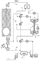
- la figure 1 schématise le procédé selon l'invention,
- la figure 2 schématise une variante du procédé selon l'invention.
La présente invention vise à séparer et capter le CO2 contenu dans ces gaz de combustion sous une pression la plus élevée possible en récupérant au mieux l'énergie contenue sous forme de chaleur dans les gaz de combustion en sortie de la turbine TG.
Les gaz de combustion en sortie de la turbine à gaz TG sont successivement refroidis dans les échangeurs de chaleur E1 puis E01, comprimés par le compresseur C1, refroidis dans l'échangeur de chaleur E02, comprimés par le compresseur C2, puis refroidis dans les échangeurs de chaleur E2 et E03, afin d'obtenir des gaz de combustion à haute pression et basse température.
Les gaz de combustion à haute pression et basse température issus de l'échangeur E03 sont introduits par le conduit 5 dans les moyens de traitement 10 adaptés pour séparer le CO2 contenu dans les gaz de combustion. Le CO2 séparé des gaz de combustion est évacué des moyens de traitement 10 par le conduit 6, par exemple vers une zone de stockage. La zone de stockage peut être un réservoir sous-terrain, par exemple une formation géologique correspondant à un réservoir pétrolier épuisé et accessible par un puits. Les gaz de combustion appauvris en CO2 sont évacués par le conduit 7.
Dans l'échangeur de chaleur E1, les gaz de combustion issus de la turbine TG échangent de la chaleur avec les gaz appauvris en CO2 issu du moyen de traitement 10.
Dans l'échangeur de chaleur E2, les gaz de combustion issus du compresseur C2 échangent de la chaleur avec les gaz appauvris en CO2 issus de la turbine T2.
Le procédé selon l'invention présente l'avantage d'effectuer une détente se rapprochant au mieux d'une détente isotherme à haute température en procédant par plusieurs étape de détente (par les turbines T1 et T2) et en effectuant des réchauffements (dans les échangeurs E1 et E2) du gaz avant chaque étape de détente. Plus le nombre d'étapes de détente précédées de réchauffement est grand, plus la détente se rapproche d'une détente isotherme haute température. Ainsi la détente des gaz dans les turbines T1 et T2 est effectuée à haute température, et de ce fait améliore l'efficacité de la détente.
Les machines C1, C2, T1 et T2 peuvent coopérer de manière à former une unique machine. Les arbres A1 et A2 peuvent être montés en tant que pignon satellite sur l'arbre principal A. Les arbres A1 et A2 peuvent coopérer avec l'arbre principal au moyen de roues dentées. Ainsi, le procédé selon l'invention est avantageusement mis en oeuvre par une machine unique. De plus, la machine unique telle que décrite précédemment permet d'équilibrer de manière automatique la puissance de compression totale exigée par les compresseurs C1 et C2 et la puissance de détente totale fournie par l'ensemble des turbines T1 et T2. L'équilibrage des puissances est réalisé indépendamment des déséquilibrages de puissance au niveau de chacun des compresseurs C1 et C2 et des turbines T1 et T2 (par exemple, le taux de compression de C1 peut être inférieur à celui de C2 tandis que le taux de détente de T2 est supérieur à celui de T1). La présence de l'arbre A engrainé par les arbres A1 et A2 assure le fonctionnement des compresseurs C1 et C2 sans source extérieure d'énergie.
Dans les trois exemples, on impose les conditions suivantes :
- les gaz de combustion sont évacués de la turbine à gaz TG à environ 550°C et à pression atmosphérique,
- les gaz de combustion sont refroidis à 40°C par les échangeurs E01 et E02 avant d'entrer dans les compresseurs C1 et C2,
- les gaz de combustion appauvris en CO2 sont réchauffés à 540°C dans l'échangeur E1 par échange de chaleur avec les gaz de combustion évacués par la turbine à gaz TG,
- la puissance totale fournie par les turbines T1 et T2 est entièrement transférée aux compresseurs C1 et C2.

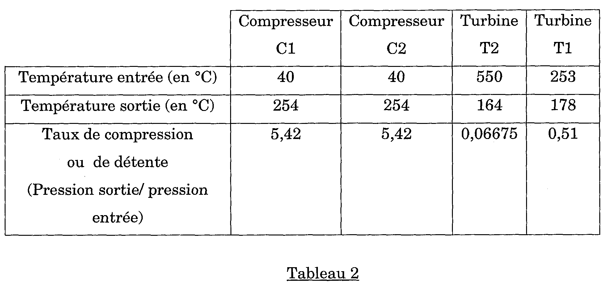
Le déséquilibrage du taux de détente entre la turbine T1 et T2 et le transfert de chaleur dans l'échangeur E2 a permis d'améliorer le taux de compression cumulé de C1 et de C2 de 25 dans les conditions de l'exemple 1 à 29,4 dans les conditions de l'exemple 2, sans apport d'énergie supplémentaire.

Le déséquilibrage du taux de compression entre le compresseur C1 et C2 et le transfert de chaleur dans l'échangeur E2 a permis d'améliorer le taux de compression cumulé de C1 et de C2 de 29,4 dans les conditions de l'exemple 2 à 33,6 dans les conditions de l'exemple 3, sans apport d'énergie supplémentaire.
Le fluide réfrigérant est évaporé dans les échangeurs E01, E02 et E03 afin de refroidir les gaz de combustion émis par la turbine à gaz TG, ainsi que les gaz d'échappement issus des compresseurs C1 et C2. En outre, le fluide réfrigérant peut être réchauffé et vaporisé par échange de chaleur indirecte avec les gaz issus de la turbine T1. Le fluide réfrigérant évaporé en sortie de l'échangeur E03 est introduit dans les moyens de détente T, par exemple une turbine. Dans les moyens de détente, le fluide est détendu à basse pression par exemple comprise entre 0,1 MPa et 2 MPa. Le fluide détendu à basse pression est refroidi et condensé dans l'échangeur de chaleur E afin d'obtenir un fluide liquéfié. L'échangeur E peut utiliser un fluide ambiant tel l'air ou l'eau comme source froide. Le fluide liquéfié est comprimé par la pompe P depuis la basse pression jusqu'à une haute pression qui peut être comprise entre 0,5 MPa et 10 MPa. Le fluide liquide à haute pression est vaporisé dans les échangeurs E01, E02 et E03, et éventuellement par échange de chaleur indirect avec les gaz issus de la turbine T1.
L'énergie absorbée par le fluide sous forme de chaleur au niveau des échangeurs E01, E02 et E03 est récupérée sous forme d'énergie mécanique sur l'arbre de la turbine T. Cette énergie mécanique peut être transformée en énergie électrique par le générateur électrique GE2. L'arbre de la turbine T peut être attelé à l'arbre de la pompe P afin de fournir l'énergie nécessaire au pompage du fluide liquéfié. Avantageusement, le compresseur C, comprimant le CO2 séparé dans les moyens 10, est entraíné grâce à l'énergie mécanique disponible sur l'arbre de la turbine T du circuit de secondaire de refroidissement. Par exemple, l'arbre du compresseur C est attelé à l'arbre de la turbine T du circuit secondaire.
Les calculs de rendement de cycle ont été réalisés à l'aide de diagrammes de Mollier. La température des sources chaudes dans les échangeurs E01, E02 et E03 est prise à titre d'exemple à 200°C, la température de la source froide dans le condenseur E est de 40°C.
| Pression évaporateur-MPa a | 4 | 10 | 20 | 38 |
| Rendement théorique-% | 13 | 20 | 23 | 25 |
| Pression évaporateur-MPa a | 1 | 2 | 10 | 20 |
| Rendement théorique-% | 7 | 12 | 22 | 23 |
| Pression évaporateur-MPa a | 2,2 | 3,4 | 5 | 10 |
| Rendement théorique-% | 18 | 21,5 | 22,5 | 21 |
La fumée est refroidie dans l'échangeur de chaleur E1, puis dans l'échangeur de chaleur E01 jusqu'à une température basse comprise entre 0°C et 100°C. La fumée à basse température est introduite dans le ballon de séparation B1. L'eau condensée lors des refroidissements dans les échangeurs de chaleur E1 et E01 est évacuée en fond du ballon B1.
La fumée évacuée en tête du ballon B1 est comprimée dans le compresseur C1. La fumée sous pression issue du compresseur C1 est refroidie dans l'échangeur de chaleur E2, puis dans l'échangeur de chaleur E02 jusqu'à une température basse comprise entre 0°C et 100°C. La fumée à basse température est introduite dans le ballon de séparation B2. L'eau condensée lors des refroidissements dans les échangeurs de chaleur E2 et E02 est évacuée en fond du ballon B2. La fumée évacuée en tête du ballon B2 est comprimée dans le compresseur C2. La fumée sous pression issue du compresseur C2 est refroidie dans l'échangeur de chaleur E2, puis dans l'échangeur de chaleur E03 jusqu'à une température basse comprise entre 0°C et 100°C. La fumée à basse température est introduite dans le ballon de séparation B3. L'eau condensée lors des refroidissements dans les échangeurs de chaleur E2 et E03 est évacuée en fond du ballon B3. La fumée évacuée en tête du ballon B3 est comprimée dans le compresseur C3. La fumée sous pression issue du compresseur C3 est refroidie dans l'échangeur de chaleur E2, puis dans l'échangeur de chaleur E04 jusqu'à une température basse comprise entre 0°C et 100°C.
La fumée à basse température est introduite dans les moyens 21 de captation sous haute pression de CO2. Le CO2 séparé de la fumée est évacué par le conduit 22, comprimé par la pompe P et envoyé vers un lieu de stockage. La fumée évacuée par le conduit 23 est appauvrie en CO2.
La fumée appauvrie en CO2 circulant dans le conduit 23 est réchauffée dans l'échangeur de chaleur E2, puis dans l'échangeur de chaleur E1. La fumée à haute température est détendue dans la turbine T3. Lors de la détente dans la turbine T3, la température de la fumée a diminué. La fumée est réchauffée dans l'échangeur de chaleur E2, puis dans l'échangeur de chaleur E1. La fumée à haute température est détendue dans la turbine T2. Lors de la détente dans la turbine T2, la température de la fumée a diminué. La fumée est réchauffée dans l'échangeur de chaleur E2, puis dans l'échangeur de chaleur E1. Ensuite, la fumée à haute température est détendue dans la turbine T1.
La fumée issue de la turbine T1 est évacuée dans l'atmosphère ou recyclée vers l'entrée de la turbine de l'installation 20.
L'échangeur E1 permet d'échanger de la chaleur entre la fumée directement issue de l'installation 20 et la fumée appauvrie en CO2 avant d'entrer dans les turbines T1, T2 et T3.
L'échangeur E2 permet d'échanger de la chaleur entre la fumée directement issue des compresseurs C1, C2 et C3 et la fumée appauvrie en CO2 avant d'entrée dans les turbines T1, T2 et T3.
Les machines C1 et T1, respectivement C2 et T2, C3 et T3, peuvent être couplées par l'arbre A1, respectivement A2, A3. Les arbres A1, A2 et A3 peuvent être couplés à un arbre principal A unique par l'intermédiaire d'engrenages.
Ainsi, les compresseurs C1, C2 et C3, et les turbines T1, T2 et T3 forment une machine unique. L'énergie mécanique obtenue lors des détentes dans les turbines T1, T2 et T3 est transférée aux compresseurs C1, C2 et C3 indépendamment des déséquilibrages des taux de compression ou de détente des machines C1, C2 et C3, et T1, T2 et T3.
Claims (8)
- Procédé de traitement d'une fumée à haute température et basse pression pour récupérer l'énergie disponible et pour capter à haute pression le dioxyde de carbone, dans lequel on effectue les étapes :a) on comprime ladite fumée à haute température et basse pression de manière à obtenir une fumée à haute pression,b) on sépare une partie du dioxyde de carbone contenu dans ladite fumée à haute pression de manière à obtenir une fumée appauvrie en dioxyde de carbone et du dioxyde de carbone à haute pression,c) on détend ladite fumée appauvrie en dioxyde de carbone de manière à obtenir une fumée détendue,d) on réchauffe ladite fumée détendue de manière à obtenir une fumée réchauffée,e) on détend ladite fumée réchauffée, en récupérant de l'énergie de détente.
- Procédé selon la revendication 1, dans lequel à l'étape d), on réchauffe ladite fumée détendue par échange de chaleur avec ladite fumée à haute pression.
- Procédé selon l'une des revendications précédentes, dans lequel avant l'étape c), on réchauffe ladite fumée appauvrie en dioxyde de carbone par échange de chaleur avec ladite fumée à haute température et basse pression.
- Procédé selon l'une des revendications précédentes, dans lequel l'énergie fournie lors des détentes effectuées aux étapes c) et e) est utilisée pour effectuer la compression à l'étape a).
- Procédé selon l'une des revendications précédentes, dans lequel le taux de détente à l'étape c) est inférieur au taux de détente à l'étape e).
- Procédé selon l'une des revendications précédentes, dans lequel à l'étape a) on effectue les étapes : i) on comprime ladite fumée à haute température et basse pression de manière à obtenir une fumée à moyenne pression, ii) on comprime ladite fumée à moyenne pression de manière à obtenir ladite fumée à haute pression, et iii) on refroidit ladite fumée à haute température et basse pression et ladite fumée à moyenne pression.
- Procédé selon la revendication 6, dans lequel le taux de compression à l'étape i) est inférieur au taux de compression à l'étape ii).
- Procédé selon l'une des revendications précédentes, dans lequel on comprime ledit dioxyde de carbone à haute pression et on injecte ledit dioxyde de carbone à haute pression dans un réservoir souterrain.
Applications Claiming Priority (2)
| Application Number | Priority Date | Filing Date | Title |
|---|---|---|---|
| FR0307034A FR2855984B1 (fr) | 2003-06-10 | 2003-06-10 | Procede de traitement de fumees |
| FR0307034 | 2003-06-10 |
Publications (2)
| Publication Number | Publication Date |
|---|---|
| EP1488843A1 true EP1488843A1 (fr) | 2004-12-22 |
| EP1488843B1 EP1488843B1 (fr) | 2007-05-16 |
Family
ID=33396771
Family Applications (1)
| Application Number | Title | Priority Date | Filing Date |
|---|---|---|---|
| EP04291264A Expired - Lifetime EP1488843B1 (fr) | 2003-06-10 | 2004-05-17 | Procédé de traitement de fumées |
Country Status (8)
| Country | Link |
|---|---|
| US (1) | US7445661B2 (fr) |
| EP (1) | EP1488843B1 (fr) |
| JP (1) | JP4563730B2 (fr) |
| AT (1) | ATE362391T1 (fr) |
| DE (1) | DE602004006465T2 (fr) |
| DK (1) | DK1488843T3 (fr) |
| FR (1) | FR2855984B1 (fr) |
| NO (1) | NO20042399L (fr) |
Families Citing this family (10)
| Publication number | Priority date | Publication date | Assignee | Title |
|---|---|---|---|---|
| US20080066469A1 (en) * | 2006-09-15 | 2008-03-20 | Scherzer Paul L | System and method for generating electrical energy utilizing recaptured carbon dioxide |
| EP2107930B1 (fr) * | 2007-01-25 | 2012-04-18 | Shell Internationale Research Maatschappij B.V. | Procédé pour limiter les émissions de dioxyde de carbone dans une centrale électrique |
| US8397482B2 (en) | 2008-05-15 | 2013-03-19 | General Electric Company | Dry 3-way catalytic reduction of gas turbine NOx |
| US20110068585A1 (en) * | 2009-09-24 | 2011-03-24 | Alstom Technology Ltd | Method and system for capturing and utilizing energy generated in a flue gas stream processing system |
| ITFI20110262A1 (it) * | 2011-12-06 | 2013-06-07 | Nuovo Pignone Spa | "heat recovery in carbon dioxide compression and compression and liquefaction systems" |
| CN107321151B (zh) * | 2016-04-29 | 2020-12-25 | 张迪霖 | 烟气净化方法及其应用 |
| JP6764798B2 (ja) | 2017-01-30 | 2020-10-07 | 三菱重工業株式会社 | プラント及びプラントの運転方法 |
| MX2020010043A (es) * | 2018-03-29 | 2021-01-08 | Xyz Energy Group Llc | Sistema y metodo para la generacion de calor y energia utilizando multiples loops que comprenden un lazo de transferencia de calor primario, un lazo de ciclo de energia y un lazo de transferencia de calor intermedio. |
| US11561047B2 (en) | 2020-09-28 | 2023-01-24 | XYZ Energy Group, LLC | System and method for thermal conversion of materials using multiple loops comprising a primary heat transfer loop, an intermediate heat transfer loop and a thermal conversion circuit |
| EP4255999A4 (fr) | 2020-12-07 | 2024-12-25 | XYZ Energy Group, LLC | Production d'énergie à boucles multiples utilisant un fluide à cycle supercritique avec récupérateur double |
Citations (3)
| Publication number | Priority date | Publication date | Assignee | Title |
|---|---|---|---|---|
| EP0551876A2 (fr) * | 1992-01-17 | 1993-07-21 | The Kansai Electric Power Co., Inc. | Procédé pour éliminer de dioxyde de carbone de gaz de combustion |
| WO2000048709A1 (fr) * | 1999-02-19 | 2000-08-24 | Norsk Hydro Asa | Technique d'elimination et de recuperation du co2 de gaz d'echappement |
| WO2000057990A1 (fr) * | 1999-03-26 | 2000-10-05 | Christensen Process Consulting As | Procede de regulation de la teneur en co2 de gaz de combustion provenant de centrales thermiques et centrale thermique utilisant le procede |
Family Cites Families (9)
| Publication number | Priority date | Publication date | Assignee | Title |
|---|---|---|---|---|
| JP2871273B2 (ja) * | 1992-03-26 | 1999-03-17 | 三菱重工業株式会社 | 二酸化炭素除去燃焼装置 |
| JPH05288079A (ja) * | 1992-04-08 | 1993-11-02 | Mitsubishi Heavy Ind Ltd | ガスタービン設備 |
| JPH0699035A (ja) * | 1992-09-21 | 1994-04-12 | Chubu Electric Power Co Inc | 排ガス中の二酸化炭素の分離回収方法 |
| JPH11241618A (ja) * | 1998-02-26 | 1999-09-07 | Toshiba Corp | ガスタービン発電プラント |
| JP2000061293A (ja) * | 1998-08-18 | 2000-02-29 | Toshiba Corp | メタンハイドレートを燃料として利用するシステム |
| DE10016079A1 (de) * | 2000-03-31 | 2001-10-04 | Alstom Power Nv | Verfahren zum Entfernen von Kohlendioxid aus dem Abgas einer Gasturbinenanlage sowie Vorrichtung zur Durchführung des Verfahrens |
| JP3690514B2 (ja) * | 2001-06-22 | 2005-08-31 | 川崎重工業株式会社 | 地下の石炭層を用いて燃料と燃焼ガスのクローズドシステムを構築したガスタービン設備 |
| JP2003148112A (ja) * | 2001-11-09 | 2003-05-21 | Toshiba Corp | タービンプラント |
| EP1540144A1 (fr) * | 2002-09-17 | 2005-06-15 | Foster Wheeler Energy Corporation | Nouveau cycle hybride de gazeification du charbon utilisant un fluide de travail recycle |
-
2003
- 2003-06-10 FR FR0307034A patent/FR2855984B1/fr not_active Expired - Fee Related
-
2004
- 2004-05-17 DK DK04291264T patent/DK1488843T3/da active
- 2004-05-17 EP EP04291264A patent/EP1488843B1/fr not_active Expired - Lifetime
- 2004-05-17 AT AT04291264T patent/ATE362391T1/de not_active IP Right Cessation
- 2004-05-17 DE DE602004006465T patent/DE602004006465T2/de not_active Expired - Lifetime
- 2004-06-08 JP JP2004169333A patent/JP4563730B2/ja not_active Expired - Fee Related
- 2004-06-08 US US10/862,433 patent/US7445661B2/en not_active Expired - Fee Related
- 2004-06-09 NO NO20042399A patent/NO20042399L/no not_active Application Discontinuation
Patent Citations (3)
| Publication number | Priority date | Publication date | Assignee | Title |
|---|---|---|---|---|
| EP0551876A2 (fr) * | 1992-01-17 | 1993-07-21 | The Kansai Electric Power Co., Inc. | Procédé pour éliminer de dioxyde de carbone de gaz de combustion |
| WO2000048709A1 (fr) * | 1999-02-19 | 2000-08-24 | Norsk Hydro Asa | Technique d'elimination et de recuperation du co2 de gaz d'echappement |
| WO2000057990A1 (fr) * | 1999-03-26 | 2000-10-05 | Christensen Process Consulting As | Procede de regulation de la teneur en co2 de gaz de combustion provenant de centrales thermiques et centrale thermique utilisant le procede |
Also Published As
| Publication number | Publication date |
|---|---|
| JP2005002996A (ja) | 2005-01-06 |
| ATE362391T1 (de) | 2007-06-15 |
| DE602004006465T2 (de) | 2008-01-17 |
| EP1488843B1 (fr) | 2007-05-16 |
| NO20042399L (no) | 2004-12-13 |
| JP4563730B2 (ja) | 2010-10-13 |
| US7445661B2 (en) | 2008-11-04 |
| DK1488843T3 (da) | 2007-09-24 |
| FR2855984A1 (fr) | 2004-12-17 |
| DE602004006465D1 (de) | 2007-06-28 |
| FR2855984B1 (fr) | 2005-07-22 |
| US20040250998A1 (en) | 2004-12-16 |
Similar Documents
| Publication | Publication Date | Title |
|---|---|---|
| FR2558893A1 (fr) | Procede de production d'energie, a l'aide d'une turbine a gaz | |
| FR2546976A1 (fr) | Installation de traitement chimique a turbine a gaz fonctionnant en cycle ferme | |
| RU2009106714A (ru) | Метод и устройство для эффективной и низкотоксичной эксплуатации электростанций, а также для аккумулирования и преобразования энергии | |
| EP1941208B1 (fr) | Procede d'oxy-combustion permettant la capture de la totalite du dioxyde de carbone produit | |
| FR2969693A1 (fr) | Centrale electrique a turbines a gaz et vapeur a cycle combine | |
| JP2021179306A (ja) | タービンシステムおよび方法 | |
| EP1488843B1 (fr) | Procédé de traitement de fumées | |
| EP1486246A2 (fr) | Procédé de traitement de fumées avec recuperation d'energie | |
| FR2970042A1 (fr) | Systeme de turbine a gaz et procede de refroidissement avec du co2 | |
| FR2981129A1 (fr) | Procede et systeme perfectionne de conversion de l'energie thermique marine. | |
| JP2003074372A (ja) | 地下の石炭層を用いて燃料と燃焼ガスのクローズドシステムを構築したガスタービン設備 | |
| CN109578098A (zh) | 零碳排放的天然气热电联供发电工艺 | |
| EP4146996B1 (fr) | Système de refroidissement, système de climatisation, ensemble moteur et procédés associés | |
| WO2009103926A2 (fr) | Intégration d'un appareil de séparation d'air et d'un cycle à réchauffage de vapeur | |
| FR3147591A1 (fr) | Turbomachine du type à injection de vapeur d’eau pour la propulsion d’un aéronef, aéronef et procédé associés | |
| FR2943125A1 (fr) | Procede de liquefaction de gaz naturel a cycle combine | |
| FR2929696A1 (fr) | Integration d'un appareil de separation d'air et d'un cycle a rechauffage de vapeur | |
| WO2025196019A1 (fr) | Procédé et installation de captage de co2 contenu dans un gaz de combustion | |
| US20260055009A1 (en) | System and method for treating wastewater from an oilfield well with co-production of power | |
| FR2827186A1 (fr) | Procede et installation de distillation d'air et de production de vapeur d'eau | |
| FR3117163A1 (fr) | procédé de stockage et de récupération d’énergie comprenant une turbine à gaz pour réchauffer le gaz comprimé à la détente | |
| FR2776018A1 (fr) | Turbo-propulsion pour navires de surface et sous-marins | |
| CN121251437A (zh) | 用于海上天然气开采平台的超临界二氧化碳发电综合系统 | |
| EP2295765A1 (fr) | Procédé de réfrigération d'air autonome, adaptable aux moteurs thermiques, dont les turbines à combustion | |
| FR2590319A1 (fr) | Procede de production d'energie a l'aide d'une turbine a gaz |
Legal Events
| Date | Code | Title | Description |
|---|---|---|---|
| PUAI | Public reference made under article 153(3) epc to a published international application that has entered the european phase |
Free format text: ORIGINAL CODE: 0009012 |
|
| AK | Designated contracting states |
Kind code of ref document: A1 Designated state(s): AT BE BG CH CY CZ DE DK EE ES FI FR GB GR HU IE IT LI LU MC NL PL PT RO SE SI SK TR |
|
| AX | Request for extension of the european patent |
Extension state: AL HR LT LV MK |
|
| 17P | Request for examination filed |
Effective date: 20050622 |
|
| AKX | Designation fees paid |
Designated state(s): AT BE BG CH CY CZ DE DK EE ES FI FR GB GR HU IE IT LI LU MC NL PL PT RO SE SI SK TR |
|
| GRAP | Despatch of communication of intention to grant a patent |
Free format text: ORIGINAL CODE: EPIDOSNIGR1 |
|
| GRAS | Grant fee paid |
Free format text: ORIGINAL CODE: EPIDOSNIGR3 |
|
| GRAA | (expected) grant |
Free format text: ORIGINAL CODE: 0009210 |
|
| AK | Designated contracting states |
Kind code of ref document: B1 Designated state(s): AT BE BG CH CY CZ DE DK EE ES FI FR GB GR HU IE IT LI LU MC NL PL PT RO SE SI SK TR |
|
| PG25 | Lapsed in a contracting state [announced via postgrant information from national office to epo] |
Ref country code: FI Free format text: LAPSE BECAUSE OF FAILURE TO SUBMIT A TRANSLATION OF THE DESCRIPTION OR TO PAY THE FEE WITHIN THE PRESCRIBED TIME-LIMIT Effective date: 20070516 |
|
| REG | Reference to a national code |
Ref country code: GB Ref legal event code: FG4D Free format text: NOT ENGLISH |
|
| REG | Reference to a national code |
Ref country code: CH Ref legal event code: EP |
|
| REG | Reference to a national code |
Ref country code: IE Ref legal event code: FG4D Free format text: LANGUAGE OF EP DOCUMENT: FRENCH |
|
| REF | Corresponds to: |
Ref document number: 602004006465 Country of ref document: DE Date of ref document: 20070628 Kind code of ref document: P |
|
| GBT | Gb: translation of ep patent filed (gb section 77(6)(a)/1977) |
Effective date: 20070723 |
|
| PG25 | Lapsed in a contracting state [announced via postgrant information from national office to epo] |
Ref country code: SE Free format text: LAPSE BECAUSE OF FAILURE TO SUBMIT A TRANSLATION OF THE DESCRIPTION OR TO PAY THE FEE WITHIN THE PRESCRIBED TIME-LIMIT Effective date: 20070816 |
|
| PG25 | Lapsed in a contracting state [announced via postgrant information from national office to epo] |
Ref country code: ES Free format text: LAPSE BECAUSE OF FAILURE TO SUBMIT A TRANSLATION OF THE DESCRIPTION OR TO PAY THE FEE WITHIN THE PRESCRIBED TIME-LIMIT Effective date: 20070827 |
|
| PG25 | Lapsed in a contracting state [announced via postgrant information from national office to epo] |
Ref country code: PL Free format text: LAPSE BECAUSE OF FAILURE TO SUBMIT A TRANSLATION OF THE DESCRIPTION OR TO PAY THE FEE WITHIN THE PRESCRIBED TIME-LIMIT Effective date: 20070516 Ref country code: AT Free format text: LAPSE BECAUSE OF FAILURE TO SUBMIT A TRANSLATION OF THE DESCRIPTION OR TO PAY THE FEE WITHIN THE PRESCRIBED TIME-LIMIT Effective date: 20070516 |
|
| REG | Reference to a national code |
Ref country code: IE Ref legal event code: FD4D |
|
| BERE | Be: lapsed |
Owner name: INSTITUT FRANCAIS DU PETROLE Effective date: 20070531 |
|
| PG25 | Lapsed in a contracting state [announced via postgrant information from national office to epo] |
Ref country code: MC Free format text: LAPSE BECAUSE OF NON-PAYMENT OF DUE FEES Effective date: 20070531 Ref country code: CZ Free format text: LAPSE BECAUSE OF FAILURE TO SUBMIT A TRANSLATION OF THE DESCRIPTION OR TO PAY THE FEE WITHIN THE PRESCRIBED TIME-LIMIT Effective date: 20070516 Ref country code: BG Free format text: LAPSE BECAUSE OF FAILURE TO SUBMIT A TRANSLATION OF THE DESCRIPTION OR TO PAY THE FEE WITHIN THE PRESCRIBED TIME-LIMIT Effective date: 20070816 Ref country code: IE Free format text: LAPSE BECAUSE OF FAILURE TO SUBMIT A TRANSLATION OF THE DESCRIPTION OR TO PAY THE FEE WITHIN THE PRESCRIBED TIME-LIMIT Effective date: 20070516 Ref country code: PT Free format text: LAPSE BECAUSE OF FAILURE TO SUBMIT A TRANSLATION OF THE DESCRIPTION OR TO PAY THE FEE WITHIN THE PRESCRIBED TIME-LIMIT Effective date: 20071016 Ref country code: SI Free format text: LAPSE BECAUSE OF FAILURE TO SUBMIT A TRANSLATION OF THE DESCRIPTION OR TO PAY THE FEE WITHIN THE PRESCRIBED TIME-LIMIT Effective date: 20070516 |
|
| PG25 | Lapsed in a contracting state [announced via postgrant information from national office to epo] |
Ref country code: SK Free format text: LAPSE BECAUSE OF FAILURE TO SUBMIT A TRANSLATION OF THE DESCRIPTION OR TO PAY THE FEE WITHIN THE PRESCRIBED TIME-LIMIT Effective date: 20070516 |
|
| PLBE | No opposition filed within time limit |
Free format text: ORIGINAL CODE: 0009261 |
|
| STAA | Information on the status of an ep patent application or granted ep patent |
Free format text: STATUS: NO OPPOSITION FILED WITHIN TIME LIMIT |
|
| PG25 | Lapsed in a contracting state [announced via postgrant information from national office to epo] |
Ref country code: BE Free format text: LAPSE BECAUSE OF NON-PAYMENT OF DUE FEES Effective date: 20070531 |
|
| 26N | No opposition filed |
Effective date: 20080219 |
|
| PG25 | Lapsed in a contracting state [announced via postgrant information from national office to epo] |
Ref country code: IT Free format text: LAPSE BECAUSE OF FAILURE TO SUBMIT A TRANSLATION OF THE DESCRIPTION OR TO PAY THE FEE WITHIN THE PRESCRIBED TIME-LIMIT Effective date: 20070516 Ref country code: GR Free format text: LAPSE BECAUSE OF FAILURE TO SUBMIT A TRANSLATION OF THE DESCRIPTION OR TO PAY THE FEE WITHIN THE PRESCRIBED TIME-LIMIT Effective date: 20070817 |
|
| PG25 | Lapsed in a contracting state [announced via postgrant information from national office to epo] |
Ref country code: RO Free format text: LAPSE BECAUSE OF FAILURE TO SUBMIT A TRANSLATION OF THE DESCRIPTION OR TO PAY THE FEE WITHIN THE PRESCRIBED TIME-LIMIT Effective date: 20070516 |
|
| REG | Reference to a national code |
Ref country code: CH Ref legal event code: PL |
|
| PG25 | Lapsed in a contracting state [announced via postgrant information from national office to epo] |
Ref country code: LI Free format text: LAPSE BECAUSE OF NON-PAYMENT OF DUE FEES Effective date: 20080531 Ref country code: EE Free format text: LAPSE BECAUSE OF FAILURE TO SUBMIT A TRANSLATION OF THE DESCRIPTION OR TO PAY THE FEE WITHIN THE PRESCRIBED TIME-LIMIT Effective date: 20070516 Ref country code: CH Free format text: LAPSE BECAUSE OF NON-PAYMENT OF DUE FEES Effective date: 20080531 |
|
| PG25 | Lapsed in a contracting state [announced via postgrant information from national office to epo] |
Ref country code: CY Free format text: LAPSE BECAUSE OF FAILURE TO SUBMIT A TRANSLATION OF THE DESCRIPTION OR TO PAY THE FEE WITHIN THE PRESCRIBED TIME-LIMIT Effective date: 20070516 |
|
| PG25 | Lapsed in a contracting state [announced via postgrant information from national office to epo] |
Ref country code: LU Free format text: LAPSE BECAUSE OF NON-PAYMENT OF DUE FEES Effective date: 20070517 |
|
| PG25 | Lapsed in a contracting state [announced via postgrant information from national office to epo] |
Ref country code: TR Free format text: LAPSE BECAUSE OF FAILURE TO SUBMIT A TRANSLATION OF THE DESCRIPTION OR TO PAY THE FEE WITHIN THE PRESCRIBED TIME-LIMIT Effective date: 20070516 Ref country code: HU Free format text: LAPSE BECAUSE OF FAILURE TO SUBMIT A TRANSLATION OF THE DESCRIPTION OR TO PAY THE FEE WITHIN THE PRESCRIBED TIME-LIMIT Effective date: 20071117 |
|
| REG | Reference to a national code |
Ref country code: FR Ref legal event code: CD |
|
| REG | Reference to a national code |
Ref country code: DE Ref legal event code: R081 Ref document number: 602004006465 Country of ref document: DE Owner name: IFP ENERGIES NOUVELLES, FR Free format text: FORMER OWNER: INSTITUT FRANCAIS DU PETROLE, RUEIL-MALMAISON, FR Effective date: 20110331 Ref country code: DE Ref legal event code: R081 Ref document number: 602004006465 Country of ref document: DE Owner name: IFP ENERGIES NOUVELLES, FR Free format text: FORMER OWNER: INSTITUT FRANCAIS DU PETROLE, RUEIL-MALMAISON, HAUTS-DE-SEINE, FR Effective date: 20110331 |
|
| PGFP | Annual fee paid to national office [announced via postgrant information from national office to epo] |
Ref country code: FR Payment date: 20110503 Year of fee payment: 8 |
|
| PGFP | Annual fee paid to national office [announced via postgrant information from national office to epo] |
Ref country code: GB Payment date: 20110525 Year of fee payment: 8 Ref country code: DK Payment date: 20110519 Year of fee payment: 8 Ref country code: NL Payment date: 20110531 Year of fee payment: 8 |
|
| PGFP | Annual fee paid to national office [announced via postgrant information from national office to epo] |
Ref country code: DE Payment date: 20110601 Year of fee payment: 8 |
|
| REG | Reference to a national code |
Ref country code: NL Ref legal event code: V1 Effective date: 20121201 |
|
| REG | Reference to a national code |
Ref country code: DK Ref legal event code: EBP |
|
| GBPC | Gb: european patent ceased through non-payment of renewal fee |
Effective date: 20120517 |
|
| REG | Reference to a national code |
Ref country code: FR Ref legal event code: ST Effective date: 20130131 |
|
| REG | Reference to a national code |
Ref country code: DE Ref legal event code: R119 Ref document number: 602004006465 Country of ref document: DE Effective date: 20121201 |
|
| PG25 | Lapsed in a contracting state [announced via postgrant information from national office to epo] |
Ref country code: NL Free format text: LAPSE BECAUSE OF NON-PAYMENT OF DUE FEES Effective date: 20121201 |
|
| PG25 | Lapsed in a contracting state [announced via postgrant information from national office to epo] |
Ref country code: GB Free format text: LAPSE BECAUSE OF NON-PAYMENT OF DUE FEES Effective date: 20120517 Ref country code: FR Free format text: LAPSE BECAUSE OF NON-PAYMENT OF DUE FEES Effective date: 20120531 Ref country code: DK Free format text: LAPSE BECAUSE OF NON-PAYMENT OF DUE FEES Effective date: 20120531 |
|
| PG25 | Lapsed in a contracting state [announced via postgrant information from national office to epo] |
Ref country code: DE Free format text: LAPSE BECAUSE OF NON-PAYMENT OF DUE FEES Effective date: 20121201 |