EP1488101B1 - Extracting power from a fluid flow - Google Patents
Extracting power from a fluid flow Download PDFInfo
- Publication number
- EP1488101B1 EP1488101B1 EP03712375A EP03712375A EP1488101B1 EP 1488101 B1 EP1488101 B1 EP 1488101B1 EP 03712375 A EP03712375 A EP 03712375A EP 03712375 A EP03712375 A EP 03712375A EP 1488101 B1 EP1488101 B1 EP 1488101B1
- Authority
- EP
- European Patent Office
- Prior art keywords
- fluid
- flow
- primary
- driving
- constriction
- Prior art date
- Legal status (The legal status is an assumption and is not a legal conclusion. Google has not performed a legal analysis and makes no representation as to the accuracy of the status listed.)
- Expired - Lifetime
Links
- 239000012530 fluid Substances 0.000 title claims abstract description 277
- 238000004891 communication Methods 0.000 claims abstract description 5
- XLYOFNOQVPJJNP-UHFFFAOYSA-N water Substances O XLYOFNOQVPJJNP-UHFFFAOYSA-N 0.000 claims description 68
- 230000003068 static effect Effects 0.000 claims description 8
- 238000011144 upstream manufacturing Methods 0.000 claims description 7
- 230000002401 inhibitory effect Effects 0.000 claims description 6
- 230000003321 amplification Effects 0.000 claims description 4
- 238000003199 nucleic acid amplification method Methods 0.000 claims description 4
- 230000004888 barrier function Effects 0.000 claims 1
- 230000000694 effects Effects 0.000 description 15
- 230000015572 biosynthetic process Effects 0.000 description 11
- 238000005755 formation reaction Methods 0.000 description 11
- 238000010586 diagram Methods 0.000 description 9
- 230000009024 positive feedback mechanism Effects 0.000 description 8
- 238000000605 extraction Methods 0.000 description 7
- 230000002829 reductive effect Effects 0.000 description 6
- 230000002706 hydrostatic effect Effects 0.000 description 5
- 230000009467 reduction Effects 0.000 description 5
- 239000007787 solid Substances 0.000 description 5
- 230000008901 benefit Effects 0.000 description 4
- 230000005540 biological transmission Effects 0.000 description 4
- 230000007423 decrease Effects 0.000 description 4
- 230000001133 acceleration Effects 0.000 description 3
- 230000001419 dependent effect Effects 0.000 description 3
- 238000009987 spinning Methods 0.000 description 3
- 230000009471 action Effects 0.000 description 2
- 230000000903 blocking effect Effects 0.000 description 2
- 238000004140 cleaning Methods 0.000 description 2
- 238000001035 drying Methods 0.000 description 2
- 238000009434 installation Methods 0.000 description 2
- 230000007246 mechanism Effects 0.000 description 2
- 150000003839 salts Chemical class 0.000 description 2
- 238000004378 air conditioning Methods 0.000 description 1
- 230000001427 coherent effect Effects 0.000 description 1
- 238000001816 cooling Methods 0.000 description 1
- 239000013078 crystal Substances 0.000 description 1
- 230000003247 decreasing effect Effects 0.000 description 1
- 230000007812 deficiency Effects 0.000 description 1
- 230000005611 electricity Effects 0.000 description 1
- 230000002708 enhancing effect Effects 0.000 description 1
- 238000003912 environmental pollution Methods 0.000 description 1
- 230000003628 erosive effect Effects 0.000 description 1
- 238000002474 experimental method Methods 0.000 description 1
- 239000006260 foam Substances 0.000 description 1
- 239000002803 fossil fuel Substances 0.000 description 1
- 230000005484 gravity Effects 0.000 description 1
- 238000011065 in-situ storage Methods 0.000 description 1
- 238000012423 maintenance Methods 0.000 description 1
- 238000000034 method Methods 0.000 description 1
- 230000008569 process Effects 0.000 description 1
- 238000009877 rendering Methods 0.000 description 1
- 230000008439 repair process Effects 0.000 description 1
- 230000000717 retained effect Effects 0.000 description 1
- 230000000630 rising effect Effects 0.000 description 1
- 230000002269 spontaneous effect Effects 0.000 description 1
- 238000012546 transfer Methods 0.000 description 1
Images

Classifications
-
- F—MECHANICAL ENGINEERING; LIGHTING; HEATING; WEAPONS; BLASTING
- F03—MACHINES OR ENGINES FOR LIQUIDS; WIND, SPRING, OR WEIGHT MOTORS; PRODUCING MECHANICAL POWER OR A REACTIVE PROPULSIVE THRUST, NOT OTHERWISE PROVIDED FOR
- F03B—MACHINES OR ENGINES FOR LIQUIDS
- F03B17/00—Other machines or engines
-
- Y—GENERAL TAGGING OF NEW TECHNOLOGICAL DEVELOPMENTS; GENERAL TAGGING OF CROSS-SECTIONAL TECHNOLOGIES SPANNING OVER SEVERAL SECTIONS OF THE IPC; TECHNICAL SUBJECTS COVERED BY FORMER USPC CROSS-REFERENCE ART COLLECTIONS [XRACs] AND DIGESTS
- Y02—TECHNOLOGIES OR APPLICATIONS FOR MITIGATION OR ADAPTATION AGAINST CLIMATE CHANGE
- Y02E—REDUCTION OF GREENHOUSE GAS [GHG] EMISSIONS, RELATED TO ENERGY GENERATION, TRANSMISSION OR DISTRIBUTION
- Y02E10/00—Energy generation through renewable energy sources
- Y02E10/20—Hydro energy
-
- Y—GENERAL TAGGING OF NEW TECHNOLOGICAL DEVELOPMENTS; GENERAL TAGGING OF CROSS-SECTIONAL TECHNOLOGIES SPANNING OVER SEVERAL SECTIONS OF THE IPC; TECHNICAL SUBJECTS COVERED BY FORMER USPC CROSS-REFERENCE ART COLLECTIONS [XRACs] AND DIGESTS
- Y02—TECHNOLOGIES OR APPLICATIONS FOR MITIGATION OR ADAPTATION AGAINST CLIMATE CHANGE
- Y02E—REDUCTION OF GREENHOUSE GAS [GHG] EMISSIONS, RELATED TO ENERGY GENERATION, TRANSMISSION OR DISTRIBUTION
- Y02E10/00—Energy generation through renewable energy sources
- Y02E10/30—Energy from the sea, e.g. using wave energy or salinity gradient
Definitions
- This invention relates to apparatus for extracting power from a fluid flow such as a tidal stream.
- WO 99/6620 discloses a device in which a fluid driveable engine such as a turbine is situated above-water. A portion of the incoming tidal stream is directed through a channel having a flow accelerating constriction and the flow of a fluid through a conduit connecting the fluid driveable engine to a portion of the channel having an accelerated fluid flow drives the fluid driveable engine.
- the speed of the fluid inflow to the flow accelerating constriction is fairly slow (around 5 m/s) so that only a low-speed water turbine can be driven by this device.
- the constriction cannot be further reduced in diameter to increase the flow acceleration without introducing punitive power losses due to friction.
- Co-pending patent application GB0206623.1 discloses a device in which the turbine is again situated above water, but the turbine is driven by an alternative fluid to that present in the fluid flow through the flow accelerating constriction.
- This system has the advantage that the fluid-driven engine can be driven by compressed air (transmission fluid) rather than water.
- Turbo-generators driven by compressed air at two or three atmospheres are much cheaper to build and maintain than low-head water turbines having comparable output capacity due to their small diameter and high speed. Use of such air driven turbo-generators obviates the need for massive watertight bearings and a gearbox.
- the system of the co-pending application uses both a primary and a secondary driving circuit (two-stage pressure
- the present invention provides an apparatus for extracting power from a fluid flow, the apparatus comprising:
- the apparatus of the present invention alleviates the disadvantages of the prior art by providing a system that is capable of introducing driving fluid directly to the flow accelerating constriction, even at large hydrostatic depths, the driving fluid being a different fluid from the primary fluid.
- This is achieved by providing a fluid directing arrangement operable to impart angular momentum (i.e. rotational flow) to the primary fluid as it enters the flow accelerating constriction.
- the rotational flow imparted by the fluid directing arrangement in co-operation with the pressure reduction created in the flow accelerating constriction, produces a positive feedback effect on the primary fluid such that a pressure reduction substantially greater than that achievable from the Bernoulli effect alone is produced along a low pressure path corresponding to the axis of rotation of the fluid in the constriction.
- the driving fluid is introduced along this low pressure path to effect its transmission through the flow accelerating constriction.
- the driving fluid having passed through the flow accelerating constriction acts to drive a fluid driveable engine.
- the fluid directing arrangement comprises at least one fluid deflector situated upstream of the flow accelerating constriction, the advantages of encouraging vortex formation at the desired location and enhancing the rotational flow in the flow accelerating channel thereby improving the suction are achieved.
- the at least one fluid deflector is a static structure. This avoids the need to have moving parts underwater and correspondingly high maintenance costs.
- Preferred embodiments comprise an air collection tank for collecting driving fluid from an outflow of the flow accelerating constnction.
- This simple air collection mechanism facilitated by the rotational flow of the primary fluid as is passes through the flow accelerating constriction allows the energy extraction to be performed using a less complex circuit It also allows for re-cirailation of the driving fluid via a simple flow path from the outlet of the flow accelerating constriction through the fluid driveable engine and directly back to the input of the flow accelerating constriction.
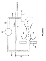
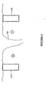
- Figure 1 is a schematic diagram of an apparatus for extracting power from a fluid flow according to a first example embodiment of the invention.
- the apparatus comprises a fluid directing arrangement 100, a conduit 200, a fluid driveable engine 300, a fluid collection tank 400 and a pair of fluid deflectors 500.
- the fluid directing arrangement 100 is a cylindrical structure. From the cross-sectional view of the cylindrical structure shown in Figure 1, it can be seen that the profile of the interior wall of the fluid directing arrangement resembles an aerofoil. The interior wall forms a channel through which fluid flows. The channel narrows to form a flow accelerating constriction through which the inflowing fluid passes before expulsion downstream at the tail of the fluid directing arrangement proximal to the fluid collection tank 400.
- Such a fluid directing arrangement 100 having a flow accelerating constriction is known as a "Venturi" since its general principle of operation is similar to that of the Venturi meter, which is used to measure the rate of fluid flow.
- the fluid flow through the fluid directing arrangement 100 will be denoted the primary fluid flow.
- Bernoulli's theorem is generally applied to systems in which there is streamline (laminar) flow. Laminar flow occurs for small flow velocities in channels having small diameter whereas turbulent flow prevails in a channel having a large flow rate. However, even if the flow through a constriction in a channel is turbulent, the pressure will fall as the bulk velocity rises as described by Bernoulli's theorem. This is because to conserve fluid volume the flow must accelerate as the channel constricts. It can be shown by calculation and by direct experiment that Bernoulli's theorem is applicable to turbulent flow just as for streamline flow.
- the conduit 200 provides a further, different fluid flow path for directing the driving fluid.
- the driving fluid (which is air in this particular embodiment) is driven down the portion 200a of the conduit to an inlet 200c close to the mouth of the fluid directing arrangement.
- the inlet 200c directs air substantially axially through the flow accelerating constriction.
- the inlet 200c formed by the conduit is at height h below the water surface.
- the air flows through the channel formed by the flow directing arrangement 100, expanding as it passes through the reduced pressure region of the flow accelerating constriction.
- the expanding air in the constriction increases the pressure of the surrounding water.
- the work done by the primary fluid against the increasing resistance of the expanding air imparts energy to the air and generates a pressure head across the flow directing formation 100.
- the air emerging from the fluid accelerating constriction should continue to pass along the axis of the vortex for some time after emerging from the fluid accelerating constriction and will thus travel towards the fluid collection tank 400 where it is collected for subsequent circulation through the fluid-driven engine 300.
- the rotational flow of the primary fluid that has already passed through the flow accelerating constriction will ultimately be obliterated by turbulence in the fluid directing arrangement.
- the compressed air passes along with the primary fluid (in this case water) through the flow accelerating constriction and is collected by the fluid collection tank 400.
- the fluid collection tank is situated adjacent to the outlet tail of the fluid directing arrangement 100 and collects driving fluid downstream of the fluid accelerating constriction.
- the fluid collection tank has radial plates which serve to at least partially remove rotational flow of the incoming driving fluid.
- the driving fluid may be collected via a slot in the upper portion of the tail of the fluid directing arrangement which feeds the driving fluid to a fluid collection tank above via an exhaust tail pipe connecting the slot to the collection tank.
- a cascade of collection trays is provided at different levels (i.e. differing distances from the central axis of the fluid directing arrangement) to intercept rising driving fluid (e.g. air) as it emerges from the flow accelerating constriction.
- Each collection tray feeds a narrow-bore vertical pipe which rises from the collection tray to a common fluid collection tank.
- compressed air from the fluid collection tank 400 flows up through the portion 200b of the conduit and is subsequently supplied to the turbine 300.
- the turbine 300 is driven by the flow of air from the air collection tank 400 to the inlet 200c via the flow accelerating constriction.
- Air is pumped down to the inlet 200c at pressure P 1 and re-emerges from the fluid directing arrangement at pressure P 2 .
- P 2 >P 1 the fluid driveable engine 300 can be driven by the pressure difference.
- the performance of the turbine is dependent upon the pressure ratio P 2 /P 1 , rather than the pressure difference.
- a pressure head is created across the Venturi.
- a pressure head is created by placing an obstruction in the water.
- the obstruction may be created by the fluid directing arrangement 100 itself (as in the embodiment of Figure 8 described below).
- the pressure head is created by a dam (not shown) situated upstream of the Venturi.
- the pressure P 1 at the inlet 200c should be sufficiently high so that air does not come out of solution.
- the pressure at the inlet 200c may be less than atmospheric pressure P 0 (P 0 is approximately equivalent to 10 metres of water) due to the suction pressure p.
- P 0 is approximately equivalent to 10 metres of water
- the pressure at the inlet 200c may be less than atmospheric pressure P 0 (P 0 is approximately equivalent to 10 metres of water) due to the suction pressure p.
- P 0 is approximately equivalent to 10 metres of water
- the pressure at the inlet 200c may be less than atmospheric pressure P 0 (P 0 is approximately equivalent to 10 metres of water) due to the suction pressure p.
- P 0 is approximately equivalent to 10 metres of water
- the pressure at the inlet 200c may be less than atmospheric pressure P 0 (P 0 is approximately equivalent to 10 metres of water) due to the suction pressure p.
- P 0 is approximately equivalent to 10 metres of water
- the pressure at the inlet 200c may be less than
- suction is a negative pressure, so a suction of -0.6 bar would correspond to a pressure of 1 - 0.6, if the suction were applied to some volume which would otherwise be at atmospheric pressure.
- suction is -0.75 bar (where 1 bar is approximately one atmosphere)
- air would be sucked into the Venturi but the suction would exactly cancel the hydrostatic pressure, so there would be no work that could be done by air going in at the input (assuming that the air is lost at the tail of the Venturi 100).
- the Venturi was to be placed just below the surface of the water, the hydrostatic pressure would be negligible.
- a pressure ratio (P 2 /P 1 ) of 1/0.25 would be obtained if the air was directed through a turbine and subsequently fed back to the Venturi mouth as input.
- the suction has to be of smaller magnitude than 19.5 m, otherwise air will come out of solution (since P 1 will be too low).
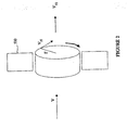
- FIG. 1 schematically illustrates a cylinder of fluid having a tidal flow velocity along the z-axis to which a component of angular velocity ⁇ has been imparted.
- deflectors 500 are used to impart angular momentum to the fluid.
- the deflectors 500 are optional since it is recognised that rotational flow may occur spontaneously in the channel of the Venturi due to small instabilities in fluid flow.
- Figure 3, described below, is an example embodiment which relies on spontaneous vortex formation.
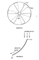
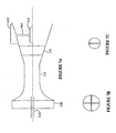
- the deflectors 500 correspond to a stator having a static array of fixed angle blades as schematically illustrated in Figure 4.
- the stator is similar in structure to a turbofan on a jet engine, although the stator has fewer blades.
- Each blade is almost triangular in shape with a very small apex angle and has a leading edge 610 and a trailing edge 620.
- the air pipe 220c enters via a central aperture 630 in the stator.
- Figure 4B schematically illustrates a single blade as viewed from the base of the triangle, with the apex pointing away from the eye.
- the blade appears as a short arc of a large circle, the arc being formed from the leading edge 610 to the trailing edge 620 of a given blade.
- the approaching primary fluid is initially parallel to the surface of the blade, but is subsequently deflected to one side by the curvature of the arc.
- the deflector imparts angular momentum to primary fluid flowing across it.
- the blades impart angular momentum r ⁇ (where r is the radius of the circular cross section of fluid) to the incoming water forcing it to rotate substantially like a solid body (i.e. in a coherent manner such that the angular velocity is constant for all water entering the system).
- An advantage of using static blades rather than blades attached to a turbine is that fixed blades can be simply be unhooked and removed from the water for cleaning. Cleaning is likely to be required due to fouling of such structures in the typical underwater environment in which the energy extraction apparatus is in installed.
- appropriately shaped deflectors without blades are used.
- a solid object is situated such that it obstructs the primary fluid as it enters the fluid directing arrangement 100. If such a solid object obstructs half of the mouth of the fluid directing arrangement, but is situated some distance away from the mouth (i.e. some distance upstream of the mouth), the stream will tend to flow into the How accelerating constriction parallel to the central axis of the constriction but from one side only.
- the incoming tidal stream has a linear velocity v along the z-axis.
- the angular rotation of the cylinder of fluid results in a centrifugal force in the non-inertial reference frame of the fluid. The centrifugal force creates a pressure differential whereby pressure increases between the centre and the circumference of the cylinder.
- the deflectors 500 have forced all water entering the fluid directing arrangement 100 to have substantially constant angular velocity ⁇ , at least initially on entry to the mouth of the fluid directing arrangement 100. Accordingly, the pressure increase due to centrifugal force is greatest at the circumference, that is, proximal to the inner wall of the channel formed by the inlet horn of the fluid directing arrangement 100.
- the radially dependent pressure increase due to centrifugal force at least partially offsets the pressure reduction (associated with the Bernoulli effect), which arises due to the increase in V rz induced by the flow accelerating constriction.
- the acceleration imparted to the water in the flow accelerating constriction is reduced in a radially dependent manner, in zccordance with the magnitude of the centrifugal force at a corresponding radius.
- V rz in the region of the central axis of the vortex is significantly greater than V rz close to the walls of the channel.
- centrifugal pressure increases radially, thereby creating a resistance to fluid motion, fluid from the outer regions of the channel is forced to flow towards the centre as the channel narrows.
- the decrease in the moment of inertia due to inward flow of fluid mass also causes an increase in angular velocity (analogous to an ice-skater pulling in her arms to effect a faster spin) to conserve angular momentum.
- r 2 ⁇ is constant and given that the centrifugal pressure is given by r 2 ⁇ 2 /2g, it follows that centrifugal pressure is equal to k ⁇ where k is a constant. Accordingly, since ⁇ increases more for more for smaller r than for larger r, it follows that centrifugal pressure also increases more for small r.
- imparting angular velocity to the primary fluid on entry to the fluid directing arrangement results in vortex formation in the channel due to a positive feedback mechanism whereby the spinning water creates a blocking effect at large radii.
- this blocking effect forces fluid mass towards the centre of the flow thereby decreasing the moment of inertia and driving an increase in angular velocity for conservation of angular momentum.
- This increase in angular velocity further increases the centrifugal pressure close to the walls of the flow accelerating constriction (i.e. at large radii).
- This positive feedback mechanism progresses until the pressure along the axis is (at least theoretically) substantially zero so that no further pressure reduction can be achieved.
- the positive feedback mechanism induced by imparting an angular velocity to the incoming fluid flow entering the mouth of the fluid directing arrangement 100, results in a large suction pressure being created along the axis of the flow accelerating constriction.
- the large suction pressure is achievable regardless of the primary stream speed v and the depth h at which the fluid accelerating constriction is situated.
- fluid flow deflectors 500 are used to impart angular momentum to the primary fluid on entry to the mouth of the Venturi.
- Imparting angular momentum to the fluid entering the mouth of the Venturi 100 significantly increases the suction relative to the suction that would be achieveable by exploiting the Bernoulli effect alone (i.e. without spinning the primary fluid).
- the hydrostatic pressure at the inlet 200c can be overcome more easily, so that the Venturi 100 may be situated at greater depth h without having recourse to forcing the air down to the inlet 200c of the conduit using an auxiliary pump.
- the driving fluid e.g. air
- primary fluid e.g. water
- an alternative embodiment which does not form part of the invention comprises all structural components of Figure 1 except the fluid flow deflectors 500.
- the air inlet portion 200c of the conduit should be situated such that it substantially coincides with the central axis of the vortex formed within the Venturi 100.
- the central axis of a spontaneously formed vortex will not necessarily coincide with the central axis of the flow accelerating constriction of the Venturi.
- the symmetry of the Venturi channel will largely determine how the vortex is spontaneously formed so that if the channel has a rotationally symmetric cross-sectional area, the central axis of the vortex and of the channel itself are likely to substantially coincide.
- the position of the conduit inlet 200c may be adjusted in situ to substantially align it with the central axis of the vortex thereby enabling flow of the driving fluid through the Venturi.
- the conduit air inlet 200c does not exactly coincide with the axis of rotation of the primary fluid, the air will always be "squeezed" towards the axis provided that the squeezing effect overwhelms the buoyancy of the air. This is because the lowest pressure is always on the axis if water is spinning.
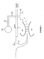
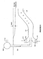
- FIG 3 is a schematic diagram of an apparatus for extracting power from a fluid flow according to a second example embodiment and does not form part of the invention.
- This second embodiment is a further example of an embodiment in which fluid deflectors are not used to create the rotational flow.
- the driving fluid air
- the driving fluid inlet is a spontaneously formed vortex 120 that extends from the water surface down to the mouth of the Venturi 100.
- Air is sucked into the core of the vortex from the atmosphere at the water's surface and air bubbles are entrained in the swirling water of the vortex which drives them down to the mouth of the Venturi 100 whereupon the air is sucked through the flow accelerating constriction to the air collection tank 400.
- the radius R v of the vortex at the water's surface is much larger than the radius of the vortex at the mouth of the Venturi.
- the axial pressure (i.e. the pressure close to the central axis of the vortex) in the flow accelerating constriction of the Venturi 100 is likely to be driven towards zero as a result of the rotational fluid flow, regardless of the depth below the water surface h, of the flow directing formation and inlet nozzle 200c.
- the device is suitable for deep-water operation.
- Embodiments of the invention use the rotational flow of water in the Venturi to achieve high suction pressures, which means that the exhaust pressure of the turbine will be low.
- the high suction pressures achievable mean that a pressure ratio (P 2 /P 1 ) of 4 is feasible, even for deep water operation, so that efficiency can be retained.
- Embodiments of the invention typically use a single stage of pressure amplification, the pressure amplification being provided by the flow accelerating constriction.
- the driving fluid e.g. air
- the Venturi 100 does not require any nozzles or inlets to operate effectively, which means that flow resistance is reduced. Since the primary fluid flows rapidly through the Venturi, fouling is less likely to be a problem in these systems.
- the positive feedback mechanism induced by the combination of the flow accelerating constriction and the rotational flow imparted by the fluid directing arrangement makes the suction pressure required for efficient turbine operation realistically achievable. If the fluid directing arrangement 100 is situated at sufficient depth, the transmission fluid (in this case air) will be sufficiently compressed that it can be used to drive the turbine 300. If, on the other hand, the fluid directing arrangement is situated only a short distance under water, the air turbine 300 is effectively driven by the suction created rather than the compressed air generated. Since the pressure differential achievable through suction is comparatively small (since water begins to foam at suction pressures around 0.75x10 5 N/m 2 ) such an air turbine would have to work on a pressure difference of around 1 atmosphere, which may not be very efficient. Accordingly operation of the device when it is situated at a significant depth below the water level (h>>12m) is preferable to shallow water operation.
- the transmission fluid in this case air
- the efficiency of the fluid directing arrangement 100 is related to its area ratio.
- the area ratio is the ratio of the cross-sectional area at the widest portion of the channel formed by the flow directing formations 100 to the cross-sectional area at the narrowest point (i.e. the throat) of the flow accelerating constriction.
- a typital area ratio would be, for example 3.5, with a throat diameter of 0.75m.
- the area ratio will be appropriately selected in view of engineering, weight and cost considerations. In general, the smaller the area ratio of the fluid directing arrangement, the greater the efficiency. However, the area ratio selected for the best possible efficiency will depend upon the speed of the incoming stream of fluid.
- the difference between the cross-sectional area at the throat of the flow accelerating constriction relative to that at the widest point need not be large.
- the wider the throat the smaller the resistance to flow of the primary fluid so that the device in which the positive feedback mechanism is employed offers improved efficiency relative to known devices.
- the inlet nozzle 200c where the driving fluid enters the flow directing formation should also have a small radius (say 0.1m or less).
- the driving fluid should have a low viscosity.
- a driving fluid such as air is appropriate for emission from a small-diameter outlet whereas water has too high a viscosity. Since the power delivered by a turbine is related to the mass of driving fluid passing through it per unit time, the density of the air is an important factor in determining energy output.
- the air inlet 200c to the Venturi 100 can have a smaller diameter if the Venturi 100 is situated at a greater depth.
- the driving fluid should be expelled such that it directly enters the low-pressure region along the central axis of the vortex. Although if the driving fluid is fed in off-axis, it should be driven towards the axis by the pressure differential created by the rotation.
- FIG 5 schematically illustrates a plan view of a further possible structure for the deflectors 500 of Figure 1.
- the deflectors are formed by static walls 510, 512 which obstruct the incoming stream of water (entering from the left in the Figure).
- One of the walls 510 is an L-shaped formation and the other is a straight wall 512.
- Water from the incoming stream passes through a gap between the L-shaped wall 510 and the straight wall 512 and the obstruction to the flow provided by the walls encourages vortex formation 120 within the space defined by the walls.
- the sense of rotation of the vortex is clockwise in this case and is indicated by an arrow.
- Figure 6 shows a side elevation of the static wall deflector structure of Figure 5.
- FIG. 7A schematically illustrates a third example embodiment of an energy extraction apparatus.
- the fluid collection tank 400 is situated in the tail of the Venturi.
- the fluid collection tank 400 comprises a collection tray 412 which extends into the channel of the Venturi and is connected to a tank 410 via a narrow channel 414 that extends through a slot in the body of the tail section of the Venturi down into the Venturi channel.
- the apparatus comprises a primary deflector 520 situated at the mouth of the Venturi which imparts rotation to fluid as it enters the fluid accelerating constriction 110 and a rotation inhibiting member 120 situated beyond the fluid accelerating constriction 110. between the primary deflector 520 and the tank 410.
- the rotation inhibiting member 120 serves to inhibit the rotational flow of fluid passing out of the fluid accelerating constriction towards the driving fluid collection tray 412.
- Figure 7B schematically illustrates a cross-sectional front view of the primary deflector 520. The deflector blades are structurally identical to those described in relation to Figures 4A and 4B.
- Figure 7C schematically illustrates a cross-section of the rotation inhibiting member 120 which comprises a vertical fin to at least partially stop rotation of fluid emerging from the fluid accelerating constriction before it passes further along the tail of the Venturi 100 to the fluid collection tray 412. Air from the water surface is supplied to the mouth of the Venturi via a conduit which leads to an air inlet pipe 210.
- the air inlet pipe 210 at the mouth of the Venturi will be generally be at atmospheric pressure P 0 whereas the air tank 410, situated at a depth H tank is at a pressure of (P 0 + ⁇ gH tank ).
- a small positive pressure p inlet where ⁇ inlet ⁇ ⁇ gH tank may need to be applied at the inlet 210 to drive air into the inlet pipe and on through the Venturi 100. Air flow from the tank 410 to the air inlet pipe 210 acts to drive the turbine 300.
- FIG. 8 schematically illustrates is an apparatus for extracting power from a fluid flow according to a fourth example embodiment of the invention.
- the fluid directing arrangement 100 has a central channel 116 which extends to form a bellmouth 112, 114 upstream of the flow accelerating constriction.
- the Venturi 100 is axially symmetric and the air inlet 200c is situated substantially on the axis of the bellmouth 112, 114.
- Identical blades 522, 524 are situated in the bellmouth such that incoming water passes through the blades as it enters the Venturi 100.
- the blades 522, 524 are slightly offset from a radius of the channel in which they are situated so that they impart angular momentum to the water before it enters the flow accelerating constriction of the main channel of the Venturi.
- the pressure at the air inlet 200c will be at less than atmospheric pressure (say at 0.25 P 0 ) due to the suction created in the channel of the Venturi.
- the Venturi channel extends up towards the water surface from constriction 116 to tail 118, the diameter of the channel increasing towards the tail.
- the obstruction presented by the Venturi to the incoming water results in a difference in water level upstream and downstream of the Venturi.
- This difference in water level ⁇ H is known as a pressure head.
- Air at atmospheric pressure P 0 enters the turbine 300 and flows down the conduit 220 to the air inlet 220c where it is entrained in the water and sucked into the Venturi channel 116.
- the entrained air bubbles expand as they rise up through the Venturi channel and encourage air and water flow through the flow accelerating constriction.
- the expanding air helps to pull the water through the Venturi channel.
- Flow of air through the flow accelerating constriction drives the turbine 300.
- the fluid driveable engine 30 could be a turbine such as a rotary vane turbine or a reciprocating engine such as a piston in a cylinder.
- a heat exchanger is situated at the exhaust of the fluid driveable engine and receives cool air generated by expansion through the fluid-driveable engine.
- the heat exchanger is used to at least partially freeze dry potentially damp air (having been entrained in the water flow on passage through the fluid directing arrangements) received by the fluid collection tank prior to circulating it through the fluid-driveable engine.
- the drying of air prior to supplying it as input to the fluid driveable engine is particularly advantageous in a marine installation.
- a heat exchanger is connected to a heat exchange circuit (e.g. a chilled water circuit) of a nearby plant such as an air conditioning plant.
- a heat exchange circuit e.g. a chilled water circuit
- the expansion of the fluid driveable engine provides cooling which can be utilised in the nearby plant. This benefit is in addition to the power generated from the fluid driveable engine.
Landscapes
- Engineering & Computer Science (AREA)
- Chemical & Material Sciences (AREA)
- Combustion & Propulsion (AREA)
- Mechanical Engineering (AREA)
- General Engineering & Computer Science (AREA)
- Other Liquid Machine Or Engine Such As Wave Power Use (AREA)
- Jet Pumps And Other Pumps (AREA)
- Physical Or Chemical Processes And Apparatus (AREA)
- External Artificial Organs (AREA)
Applications Claiming Priority (5)
| Application Number | Priority Date | Filing Date | Title |
|---|---|---|---|
| GB0206623 | 2002-03-20 | ||
| GBGB0206623.1A GB0206623D0 (en) | 2002-03-20 | 2002-03-20 | Extracting power from a fluid flow |
| GBGB0229783.6A GB0229783D0 (en) | 2002-03-20 | 2002-12-20 | Extracting power from a fluid flow |
| GB0229783 | 2002-12-20 | ||
| PCT/GB2003/001171 WO2003081029A1 (en) | 2002-03-20 | 2003-03-19 | Extracting power from a fluid flow |
Publications (2)
| Publication Number | Publication Date |
|---|---|
| EP1488101A1 EP1488101A1 (en) | 2004-12-22 |
| EP1488101B1 true EP1488101B1 (en) | 2006-06-14 |
Family
ID=28456021
Family Applications (1)
| Application Number | Title | Priority Date | Filing Date |
|---|---|---|---|
| EP03712375A Expired - Lifetime EP1488101B1 (en) | 2002-03-20 | 2003-03-19 | Extracting power from a fluid flow |
Country Status (12)
| Country | Link |
|---|---|
| US (1) | US7150149B2 (enExample) |
| EP (1) | EP1488101B1 (enExample) |
| JP (1) | JP2005520984A (enExample) |
| CN (1) | CN1643247A (enExample) |
| AT (1) | ATE330120T1 (enExample) |
| AU (1) | AU2003216837B2 (enExample) |
| CA (1) | CA2478859C (enExample) |
| DE (1) | DE60306126D1 (enExample) |
| ES (1) | ES2266794T3 (enExample) |
| NZ (1) | NZ535961A (enExample) |
| PT (1) | PT1488101E (enExample) |
| WO (1) | WO2003081029A1 (enExample) |
Families Citing this family (22)
| Publication number | Priority date | Publication date | Assignee | Title |
|---|---|---|---|---|
| US8446031B2 (en) | 2006-08-03 | 2013-05-21 | Verderg Ltd | Apparatus for converting energy from wave or current flow using pipes acting as venturi pumps |
| GB2443195B8 (en) * | 2006-08-03 | 2010-05-05 | Verderg Ltd | Apparatus for converting energy from wave or current flows |
| RU2347940C1 (ru) * | 2007-09-21 | 2009-02-27 | Виктор Михайлович Лятхер | Волновая энергетическая установка |
| JP5539893B2 (ja) * | 2007-11-16 | 2014-07-02 | エレメンタル・エナジー・テクノロジーズ・リミテッド | 動力発生機 |
| US20100283248A1 (en) | 2009-02-20 | 2010-11-11 | Moffat Brian L | Venturi based ocean wave energy conversion system |
| US8925313B2 (en) * | 2008-02-22 | 2015-01-06 | Brian Lee Moffat | Wave energy conversion apparatus |
| GB2463268B (en) * | 2008-09-05 | 2012-02-29 | Derek James Wallace Mcminn | Fluid power generator |
| US8890352B2 (en) | 2008-09-05 | 2014-11-18 | Derek James Wallace McMinn | Power generator for extracting energy from a liquid flow |
| ES2373892B1 (es) * | 2009-01-27 | 2012-11-19 | Leopoldo Alandete Jurado | Sistema para establecer una corriente de fluido mediante succión en una corriente de agua. |
| GB2471280B (en) | 2009-06-22 | 2011-08-31 | Hydroventuri Ltd | Apparatus and method for introducing a gas into a liquid |
| US9127639B2 (en) * | 2009-11-02 | 2015-09-08 | Michael Y. Cho | System and method for water expulsion from underwater hydropower plant and hydropower plant associated therewith |
| CA2792983C (en) | 2010-03-16 | 2018-06-26 | Verderg Ltd | Apparatus for generating power from fluid flow |
| DE102010020685A1 (de) * | 2010-05-15 | 2011-11-17 | Klaus Bußmann | Flussströmungskraftanlage |
| US20110278845A1 (en) * | 2010-05-16 | 2011-11-17 | Davis Sr Albert Hamilton | Waterfall High Pressure Energy Conversion Machine |
| WO2012000105A1 (en) * | 2010-06-30 | 2012-01-05 | Southern Alberta Institute Of Technology | Apparatus for extracting energy from a fluid flow |
| GB2503250B (en) | 2012-06-20 | 2015-05-27 | Verderg Ltd | Apparatus for converting energy from fluid flow |
| GB2524782B (en) | 2014-04-02 | 2016-04-20 | Verderg Ltd | Turbine assembly |
| GB201423276D0 (en) | 2014-12-28 | 2015-02-11 | Mcnulty John | Cohering, concentrating convective current producer and methods of initiating and harnessing convective currents |
| KR102323744B1 (ko) | 2015-01-15 | 2021-11-09 | 제너럴 퓨전 아이엔씨. | 회전 유체에 와류 공동을 생성하기 위한 장치 및 방법 |
| CN108488029B (zh) * | 2018-05-03 | 2024-02-13 | 广东电网有限责任公司 | 发动机及发电机 |
| MX392858B (es) * | 2019-01-28 | 2025-03-24 | Fabian Bricio Arzubide Alvaro | Impulsor cinético vectorial. |
| CN110792479B (zh) * | 2019-11-07 | 2020-07-28 | 安徽伯华氢能源科技有限公司 | 一种氢气发电系统 |
Family Cites Families (9)
| Publication number | Priority date | Publication date | Assignee | Title |
|---|---|---|---|---|
| US680951A (en) * | 1901-01-31 | 1901-08-20 | Addison G Waterhouse | Hydraulic air-compressor. |
| US1005911A (en) * | 1911-01-21 | 1911-10-17 | Francis P Wilbur | Hydraulic-power air-compressor. |
| US4307299A (en) * | 1977-07-25 | 1981-12-22 | Norton Joseph R | System for generating electrical energy utilizing combined water power and combustible fuel sources |
| US4372113A (en) * | 1981-01-15 | 1983-02-08 | Ramer James L | Pipeline energy recapture device |
| US4868408A (en) * | 1988-09-12 | 1989-09-19 | Frank Hesh | Portable water-powered electric generator |
| US5142870A (en) * | 1988-11-08 | 1992-09-01 | Angle Lonnie L | Hydraulic compressor and fuel fired turbine apparatus |
| GB9009559D0 (en) | 1990-04-27 | 1990-06-20 | Hydro Energy Ass Ltd | Hydro-electric power conversion system |
| GB9901350D0 (en) | 1998-06-12 | 1999-03-10 | Imperial College | Apparatus for extracting power from a fluid flow |
| US6546723B1 (en) * | 2001-10-09 | 2003-04-15 | The United States Of America As Represented By The Secretary Of The Navy | Hydropower conversion system |
-
2003
- 2003-03-19 JP JP2003578734A patent/JP2005520984A/ja active Pending
- 2003-03-19 CN CNA038064251A patent/CN1643247A/zh active Pending
- 2003-03-19 AU AU2003216837A patent/AU2003216837B2/en not_active Ceased
- 2003-03-19 CA CA2478859A patent/CA2478859C/en not_active Expired - Fee Related
- 2003-03-19 EP EP03712375A patent/EP1488101B1/en not_active Expired - Lifetime
- 2003-03-19 ES ES03712375T patent/ES2266794T3/es not_active Expired - Lifetime
- 2003-03-19 NZ NZ535961A patent/NZ535961A/en not_active IP Right Cessation
- 2003-03-19 US US10/508,316 patent/US7150149B2/en not_active Expired - Fee Related
- 2003-03-19 WO PCT/GB2003/001171 patent/WO2003081029A1/en not_active Ceased
- 2003-03-19 AT AT03712375T patent/ATE330120T1/de not_active IP Right Cessation
- 2003-03-19 PT PT03712375T patent/PT1488101E/pt unknown
- 2003-03-19 DE DE60306126T patent/DE60306126D1/de not_active Expired - Lifetime
Also Published As
| Publication number | Publication date |
|---|---|
| CA2478859A1 (en) | 2003-10-02 |
| NZ535961A (en) | 2006-11-30 |
| CN1643247A (zh) | 2005-07-20 |
| ATE330120T1 (de) | 2006-07-15 |
| US20050081517A1 (en) | 2005-04-21 |
| AU2003216837B2 (en) | 2008-07-31 |
| US7150149B2 (en) | 2006-12-19 |
| PT1488101E (pt) | 2006-10-31 |
| EP1488101A1 (en) | 2004-12-22 |
| CA2478859C (en) | 2010-08-17 |
| DE60306126D1 (de) | 2006-07-27 |
| AU2003216837A1 (en) | 2003-10-08 |
| WO2003081029A1 (en) | 2003-10-02 |
| ES2266794T3 (es) | 2007-03-01 |
| JP2005520984A (ja) | 2005-07-14 |
Similar Documents
| Publication | Publication Date | Title |
|---|---|---|
| EP1488101B1 (en) | Extracting power from a fluid flow | |
| US10920793B2 (en) | Energy recovery-recycling turbine integrated with a capillary tube gas compressor | |
| Choi et al. | Performance and internal flow characteristics of a cross-flow hydro turbine by the shapes of nozzle and runner blade | |
| CN101889128B (zh) | 涡轮组件 | |
| JP5019290B2 (ja) | 低圧タービンによる水力発電方法とその水力発電装置 | |
| US9322385B1 (en) | Hydro vortex enabled turbine generator | |
| AU750680B2 (en) | Apparatus for extracting power from a fluid flow | |
| BR112016022914B1 (pt) | Aparelho e sistema para gerar eletricidade a partir de fluxo de água | |
| JP6049749B2 (ja) | タービン装置 | |
| US7645115B2 (en) | System, method, and apparatus for a power producing linear fluid impulse machine | |
| US8376699B1 (en) | Vortex hydro turbine | |
| WO2010071976A1 (en) | Multiple augmented turbine assembly | |
| Kulkarni et al. | Experimental validation of computational design of wind turbine with wind lens | |
| CN110878736A (zh) | 一种水平轴尾流扩散式风力机技术 | |
| CN119975745B (zh) | 一种多工况喷水推进装置 | |
| US12129772B1 (en) | Induced flow generator apparatus for power generation | |
| JPH05141340A (ja) | 小流速大量流水中の水力発電方法 | |
| RU123849U1 (ru) | Энергетическая установка для преобразования энергии воды в механическую | |
| CN114517762B (zh) | 一种集流式海流能水轮机装置 | |
| BR102022023259B1 (pt) | Hidroturbina com difusor de flange curto e aletas estruturais | |
| GB2486297A (en) | Pelton turbines with funnel shaped separator | |
| CN103380276B (zh) | 转子装置 | |
| RU139031U1 (ru) | Устройство для утилизации энергии текущей среды | |
| KHUDOYBERDIEV | ANALYSIS OF A NEW TYPE OF MICRO-HYDRO POWER PLANT | |
| CN103380276A (zh) | 转子装置 |
Legal Events
| Date | Code | Title | Description |
|---|---|---|---|
| PUAI | Public reference made under article 153(3) epc to a published international application that has entered the european phase |
Free format text: ORIGINAL CODE: 0009012 |
|
| AK | Designated contracting states |
Kind code of ref document: A1 Designated state(s): AT BE BG CH CY CZ DE DK EE ES FI FR GB GR HU IE IT LI LU MC NL PT RO SE SI SK TR |
|
| AX | Request for extension of the european patent |
Extension state: AL LT LV MK |
|
| 17P | Request for examination filed |
Effective date: 20041018 |
|
| GRAP | Despatch of communication of intention to grant a patent |
Free format text: ORIGINAL CODE: EPIDOSNIGR1 |
|
| GRAS | Grant fee paid |
Free format text: ORIGINAL CODE: EPIDOSNIGR3 |
|
| GRAA | (expected) grant |
Free format text: ORIGINAL CODE: 0009210 |
|
| AK | Designated contracting states |
Kind code of ref document: B1 Designated state(s): AT BE BG CH CY CZ DE DK EE ES FI FR GB GR HU IE IT LI LU MC NL PT RO SE SI SK TR |
|
| PG25 | Lapsed in a contracting state [announced via postgrant information from national office to epo] |
Ref country code: SK Free format text: LAPSE BECAUSE OF FAILURE TO SUBMIT A TRANSLATION OF THE DESCRIPTION OR TO PAY THE FEE WITHIN THE PRESCRIBED TIME-LIMIT Effective date: 20060614 Ref country code: SI Free format text: LAPSE BECAUSE OF FAILURE TO SUBMIT A TRANSLATION OF THE DESCRIPTION OR TO PAY THE FEE WITHIN THE PRESCRIBED TIME-LIMIT Effective date: 20060614 Ref country code: IT Free format text: LAPSE BECAUSE OF FAILURE TO SUBMIT A TRANSLATION OF THE DESCRIPTION OR TO PAY THE FEE WITHIN THE PRESCRIBED TIME-LIMIT;WARNING: LAPSES OF ITALIAN PATENTS WITH EFFECTIVE DATE BEFORE 2007 MAY HAVE OCCURRED AT ANY TIME BEFORE 2007. THE CORRECT EFFECTIVE DATE MAY BE DIFFERENT FROM THE ONE RECORDED. Effective date: 20060614 Ref country code: BE Free format text: LAPSE BECAUSE OF FAILURE TO SUBMIT A TRANSLATION OF THE DESCRIPTION OR TO PAY THE FEE WITHIN THE PRESCRIBED TIME-LIMIT Effective date: 20060614 Ref country code: NL Free format text: LAPSE BECAUSE OF FAILURE TO SUBMIT A TRANSLATION OF THE DESCRIPTION OR TO PAY THE FEE WITHIN THE PRESCRIBED TIME-LIMIT Effective date: 20060614 Ref country code: CZ Free format text: LAPSE BECAUSE OF FAILURE TO SUBMIT A TRANSLATION OF THE DESCRIPTION OR TO PAY THE FEE WITHIN THE PRESCRIBED TIME-LIMIT Effective date: 20060614 Ref country code: AT Free format text: LAPSE BECAUSE OF FAILURE TO SUBMIT A TRANSLATION OF THE DESCRIPTION OR TO PAY THE FEE WITHIN THE PRESCRIBED TIME-LIMIT Effective date: 20060614 Ref country code: CH Free format text: LAPSE BECAUSE OF FAILURE TO SUBMIT A TRANSLATION OF THE DESCRIPTION OR TO PAY THE FEE WITHIN THE PRESCRIBED TIME-LIMIT Effective date: 20060614 Ref country code: FI Free format text: LAPSE BECAUSE OF FAILURE TO SUBMIT A TRANSLATION OF THE DESCRIPTION OR TO PAY THE FEE WITHIN THE PRESCRIBED TIME-LIMIT Effective date: 20060614 Ref country code: RO Free format text: LAPSE BECAUSE OF FAILURE TO SUBMIT A TRANSLATION OF THE DESCRIPTION OR TO PAY THE FEE WITHIN THE PRESCRIBED TIME-LIMIT Effective date: 20060614 Ref country code: LI Free format text: LAPSE BECAUSE OF FAILURE TO SUBMIT A TRANSLATION OF THE DESCRIPTION OR TO PAY THE FEE WITHIN THE PRESCRIBED TIME-LIMIT Effective date: 20060614 |
|
| REG | Reference to a national code |
Ref country code: GB Ref legal event code: FG4D |
|
| REG | Reference to a national code |
Ref country code: CH Ref legal event code: EP |
|
| REG | Reference to a national code |
Ref country code: IE Ref legal event code: FG4D |
|
| REF | Corresponds to: |
Ref document number: 60306126 Country of ref document: DE Date of ref document: 20060727 Kind code of ref document: P |
|
| PG25 | Lapsed in a contracting state [announced via postgrant information from national office to epo] |
Ref country code: SE Free format text: LAPSE BECAUSE OF FAILURE TO SUBMIT A TRANSLATION OF THE DESCRIPTION OR TO PAY THE FEE WITHIN THE PRESCRIBED TIME-LIMIT Effective date: 20060914 Ref country code: DK Free format text: LAPSE BECAUSE OF FAILURE TO SUBMIT A TRANSLATION OF THE DESCRIPTION OR TO PAY THE FEE WITHIN THE PRESCRIBED TIME-LIMIT Effective date: 20060914 |
|
| PG25 | Lapsed in a contracting state [announced via postgrant information from national office to epo] |
Ref country code: DE Free format text: LAPSE BECAUSE OF FAILURE TO SUBMIT A TRANSLATION OF THE DESCRIPTION OR TO PAY THE FEE WITHIN THE PRESCRIBED TIME-LIMIT Effective date: 20060915 |
|
| RAP2 | Party data changed (patent owner data changed or rights of a patent transferred) |
Owner name: HYDROVENTURI LIMITED |
|
| REG | Reference to a national code |
Ref country code: PT Ref legal event code: SC4A Effective date: 20060912 |
|
| NLV1 | Nl: lapsed or annulled due to failure to fulfill the requirements of art. 29p and 29m of the patents act | ||
| REG | Reference to a national code |
Ref country code: CH Ref legal event code: PL |
|
| ET | Fr: translation filed | ||
| REG | Reference to a national code |
Ref country code: ES Ref legal event code: FG2A Ref document number: 2266794 Country of ref document: ES Kind code of ref document: T3 |
|
| PLBE | No opposition filed within time limit |
Free format text: ORIGINAL CODE: 0009261 |
|
| STAA | Information on the status of an ep patent application or granted ep patent |
Free format text: STATUS: NO OPPOSITION FILED WITHIN TIME LIMIT |
|
| 26N | No opposition filed |
Effective date: 20070315 |
|
| PG25 | Lapsed in a contracting state [announced via postgrant information from national office to epo] |
Ref country code: IE Free format text: LAPSE BECAUSE OF NON-PAYMENT OF DUE FEES Effective date: 20070319 Ref country code: MC Free format text: LAPSE BECAUSE OF NON-PAYMENT OF DUE FEES Effective date: 20070331 |
|
| PG25 | Lapsed in a contracting state [announced via postgrant information from national office to epo] |
Ref country code: GR Free format text: LAPSE BECAUSE OF FAILURE TO SUBMIT A TRANSLATION OF THE DESCRIPTION OR TO PAY THE FEE WITHIN THE PRESCRIBED TIME-LIMIT Effective date: 20060915 |
|
| PG25 | Lapsed in a contracting state [announced via postgrant information from national office to epo] |
Ref country code: BG Free format text: LAPSE BECAUSE OF FAILURE TO SUBMIT A TRANSLATION OF THE DESCRIPTION OR TO PAY THE FEE WITHIN THE PRESCRIBED TIME-LIMIT Effective date: 20060914 |
|
| PG25 | Lapsed in a contracting state [announced via postgrant information from national office to epo] |
Ref country code: EE Free format text: LAPSE BECAUSE OF FAILURE TO SUBMIT A TRANSLATION OF THE DESCRIPTION OR TO PAY THE FEE WITHIN THE PRESCRIBED TIME-LIMIT Effective date: 20060614 |
|
| PG25 | Lapsed in a contracting state [announced via postgrant information from national office to epo] |
Ref country code: CY Free format text: LAPSE BECAUSE OF FAILURE TO SUBMIT A TRANSLATION OF THE DESCRIPTION OR TO PAY THE FEE WITHIN THE PRESCRIBED TIME-LIMIT Effective date: 20060614 Ref country code: LU Free format text: LAPSE BECAUSE OF NON-PAYMENT OF DUE FEES Effective date: 20070319 |
|
| PG25 | Lapsed in a contracting state [announced via postgrant information from national office to epo] |
Ref country code: HU Free format text: LAPSE BECAUSE OF FAILURE TO SUBMIT A TRANSLATION OF THE DESCRIPTION OR TO PAY THE FEE WITHIN THE PRESCRIBED TIME-LIMIT Effective date: 20061215 Ref country code: TR Free format text: LAPSE BECAUSE OF FAILURE TO SUBMIT A TRANSLATION OF THE DESCRIPTION OR TO PAY THE FEE WITHIN THE PRESCRIBED TIME-LIMIT Effective date: 20060614 |
|
| PGFP | Annual fee paid to national office [announced via postgrant information from national office to epo] |
Ref country code: PT Payment date: 20110117 Year of fee payment: 9 |
|
| PGFP | Annual fee paid to national office [announced via postgrant information from national office to epo] |
Ref country code: FR Payment date: 20120319 Year of fee payment: 10 |
|
| REG | Reference to a national code |
Ref country code: PT Ref legal event code: MM4A Free format text: LAPSE DUE TO NON-PAYMENT OF FEES Effective date: 20120919 |
|
| PG25 | Lapsed in a contracting state [announced via postgrant information from national office to epo] |
Ref country code: PT Free format text: LAPSE BECAUSE OF NON-PAYMENT OF DUE FEES Effective date: 20120919 |
|
| PGFP | Annual fee paid to national office [announced via postgrant information from national office to epo] |
Ref country code: ES Payment date: 20120928 Year of fee payment: 10 |
|
| REG | Reference to a national code |
Ref country code: FR Ref legal event code: ST Effective date: 20131129 |
|
| PG25 | Lapsed in a contracting state [announced via postgrant information from national office to epo] |
Ref country code: FR Free format text: LAPSE BECAUSE OF NON-PAYMENT OF DUE FEES Effective date: 20130402 |
|
| REG | Reference to a national code |
Ref country code: ES Ref legal event code: FD2A Effective date: 20140610 |
|
| PG25 | Lapsed in a contracting state [announced via postgrant information from national office to epo] |
Ref country code: ES Free format text: LAPSE BECAUSE OF NON-PAYMENT OF DUE FEES Effective date: 20130320 |
|
| PGFP | Annual fee paid to national office [announced via postgrant information from national office to epo] |
Ref country code: GB Payment date: 20150316 Year of fee payment: 13 |
|
| GBPC | Gb: european patent ceased through non-payment of renewal fee |
Effective date: 20160319 |
|
| PG25 | Lapsed in a contracting state [announced via postgrant information from national office to epo] |
Ref country code: GB Free format text: LAPSE BECAUSE OF NON-PAYMENT OF DUE FEES Effective date: 20160319 |