EP1487733B1 - Apparatus and method for lifting aerial cables - Google Patents
Apparatus and method for lifting aerial cables Download PDFInfo
- Publication number
- EP1487733B1 EP1487733B1 EP03702219A EP03702219A EP1487733B1 EP 1487733 B1 EP1487733 B1 EP 1487733B1 EP 03702219 A EP03702219 A EP 03702219A EP 03702219 A EP03702219 A EP 03702219A EP 1487733 B1 EP1487733 B1 EP 1487733B1
- Authority
- EP
- European Patent Office
- Prior art keywords
- telescopic member
- cable
- housing
- telescopic
- lifting
- Prior art date
- Legal status (The legal status is an assumption and is not a legal conclusion. Google has not performed a legal analysis and makes no representation as to the accuracy of the status listed.)
- Expired - Lifetime
Links
Images


Classifications
-
- B—PERFORMING OPERATIONS; TRANSPORTING
- B66—HOISTING; LIFTING; HAULING
- B66F—HOISTING, LIFTING, HAULING OR PUSHING, NOT OTHERWISE PROVIDED FOR, e.g. DEVICES WHICH APPLY A LIFTING OR PUSHING FORCE DIRECTLY TO THE SURFACE OF A LOAD
- B66F3/00—Devices, e.g. jacks, adapted for uninterrupted lifting of loads
- B66F3/24—Devices, e.g. jacks, adapted for uninterrupted lifting of loads fluid-pressure operated
- B66F3/25—Constructional features
- B66F3/26—Adaptations or arrangements of pistons
- B66F3/28—Adaptations or arrangements of pistons telescopic
-
- H—ELECTRICITY
- H02—GENERATION; CONVERSION OR DISTRIBUTION OF ELECTRIC POWER
- H02G—INSTALLATION OF ELECTRIC CABLES OR LINES, OR OF COMBINED OPTICAL AND ELECTRIC CABLES OR LINES
- H02G1/00—Methods or apparatus specially adapted for installing, maintaining, repairing or dismantling electric cables or lines
- H02G1/02—Methods or apparatus specially adapted for installing, maintaining, repairing or dismantling electric cables or lines for overhead lines or cables
-
- B—PERFORMING OPERATIONS; TRANSPORTING
- B66—HOISTING; LIFTING; HAULING
- B66F—HOISTING, LIFTING, HAULING OR PUSHING, NOT OTHERWISE PROVIDED FOR, e.g. DEVICES WHICH APPLY A LIFTING OR PUSHING FORCE DIRECTLY TO THE SURFACE OF A LOAD
- B66F11/00—Lifting devices specially adapted for particular uses not otherwise provided for
-
- H—ELECTRICITY
- H02—GENERATION; CONVERSION OR DISTRIBUTION OF ELECTRIC POWER
- H02G—INSTALLATION OF ELECTRIC CABLES OR LINES, OR OF COMBINED OPTICAL AND ELECTRIC CABLES OR LINES
- H02G7/00—Overhead installations of electric lines or cables
-
- Y—GENERAL TAGGING OF NEW TECHNOLOGICAL DEVELOPMENTS; GENERAL TAGGING OF CROSS-SECTIONAL TECHNOLOGIES SPANNING OVER SEVERAL SECTIONS OF THE IPC; TECHNICAL SUBJECTS COVERED BY FORMER USPC CROSS-REFERENCE ART COLLECTIONS [XRACs] AND DIGESTS
- Y10—TECHNICAL SUBJECTS COVERED BY FORMER USPC
- Y10T—TECHNICAL SUBJECTS COVERED BY FORMER US CLASSIFICATION
- Y10T403/00—Joints and connections
- Y10T403/32—Articulated members
- Y10T403/32254—Lockable at fixed position
- Y10T403/32467—Telescoping members
Definitions
- This invention relates to an apparatus and method for lifting aerial cables such as overhead electrified cables.
- the invention concerns a portable telescopic apparatus for lifting one or more aerial cables.
- a common problem encountered by trucks carrying oversized loads is that their journey along a road may be obstructed by an overhead electrified cable or other type of aerial cable.
- the standard practices for overcoming this problem are to lift the cable using hydraulic lifting equipment (ie. a "cherry picker") or to manually lift and hold the cable with hand-held “lift sticks". Two or more cherry pickers and operators may be needed to lift and hold a cable in the lifted position until the oversized load has passed beneath the cable. In situations where there are multiple aerial cables, the number of operators and cherry pickers needed to lift the cables will typically increase.
- Some of the disadvantages of the above practices are: that they may involve an operator physically lifting and holding a cable for an extended period of time and the cable may weigh as much as 30 kg; since a cherry picker is typically operated from within a bucket of the cherry picker, the operator may be in dangerously close proximity of an electrified cable; and, the practices may be costly and time consuming, particularly when many operators and cherry pickers are required.
- US Patent Number 1, 384, 761 describes a cable-tie hanger for positioning cable ties or hooks and for securing a current-carrying cable to the usual wire rope or supporting cable.
- the hanger has an extensible pole, which is held at a lower end by an operator, and a pull cable connected to the pole that enables the operator to extend the pole.
- portable apparatus for lifting at least one aerial cable
- said apparatus comprising: an elongate housing; at least a first telescopic member extendible from and retractable into the elongate housing; a drive operable at the elongate housing for extending and retracting the first telescopic member; and at least one cable-engaging member positionable by the first telescopic member for lifting said at least one aerial cable when the first telescopic member has extended, characterized in that a ground-bearing base of said housing is wedge-shaped and is adapted to pivot relative to the ground about an edge of the wedge to follow movement of the aerial cable should the aerial cable sway after having been lifted.
- the drive can include, for instance, an electric motor, a hydraulic motor, an engine, a chain lever block, a hand winch, a hoist arrangement, a jacking arrangement or any suitable combination of the aforementioned.
- the drive comprises a chain lever block.
- the chain lever block can be mounted to the elongate housing and the chain of the chain lever block can be attached to a lower end of the first telescopic member.
- the block of the chain lever block can be located within the elongate housing and the operative lever of the chain lever block can extend from within the elongate housing.
- the elongate housing can have separate compartments for containing parts of the chain extending from opposite sides of the block, so as to prevent entanglement of the chain.
- the elongate housing can be of any suitable size, shape and construction.
- the elongate housing is a tube of rectangular cross-section.
- the elongate housing can have internal walls/guides to ensure that the first telescopic member extends and retracts correctly.
- the apparatus Whilst supporting the aerial cable, the apparatus is free standing and can pivot relative to the ground to follow movement of the cable.
- a ground-bearing base of the elongate housing is adapted for pivoting.
- the base can be of any suitable shape, size and construction.
- the base is wedge-shaped and the apparatus can pivot relative to the ground about an edge of the wedge.
- the apparatus can comprise any suitable number of telescopic members.
- the apparatus includes a second telescopic member extendible from and retractable into the first telescopic member, and the cable-engaging member is attached to the second telescopic member.
- the first and second telescopic members can be of any suitable size, shape and construction.
- the first telescopic member comprises a tube of rectangular cross-section and the second telescopic member comprises a tube of circular cross-section.
- the drive further comprises a pulley arrangement for extending and retracting the second telescopic member.
- the pulley arrangement can have at least one sheave attached to an upper end of the first telescopic member and a flexible tie of the pulley arrangement can extend around the sheave and have respective ends attached to a lower end of the second telescopic member and to a lower end of the elongate housing.
- the flexible tie can be, for instance, a wire cable or a cord.
- the apparatus can have a locking mechanism for ensuring that the first and second telescopic members cannot extend or retract unless the chain lever block is first operated. Any suitable type of locking mechanism can be used.
- the cable-engaging member can be of any suitable size, shape and construction. Depending on how many telescopic members the apparatus has, the cable-engaging member can be attached to the second telescopic member or to first telescopic member. The cable-engaging member can be attached in any suitable way. The apparatus can have any suitable number of cable-engaging members.
- the cable-engaging member preferably has a body and a headpiece extending from the body.
- a lower end of the body can be removably attached to an upper end of the second telescopic member.
- the body is attached such that the cable-engaging member and telescopic member cannot rotate relative to one another. This may be achieved by providing the second telescopic member and body with, for instance, a pin and slot arrangement, a tongue and groove arrangement, or a bayonet arrangement.
- the cable-engaging member can have a fork, tines, a groove, a channel, a recess or any other suitable formation by which a cable can be engaged and lifted.
- the apparatus can be used to lift a plurality of cables at any one time in which case the cable-engaging member can have a plurality of forks, grooves etc.
- the forks, grooves etc. can be located at the headpiece and/or the body.
- the headpiece has an undulating surface, much like the working end of a rake, wherein individual cables are receivable within separate grooves of the undulating surface. With this arrangement, the cables can be kept in isolation from one another when being lifted.
- the headpiece and/or body has at least one fork or recess for engaging and lifting at least one cable.
- the apparatus is compact and lightweight.
- the apparatus can consist of any suitable material or materials such as, for example, metal, plastics material, and composites.
- the apparatus, or parts thereof can be insulated.
- the cable-engaging member can be insulated.
- a method for raising at least one aerial cable comprising the steps of: a) positioning a lifting apparatus beneath an aerial cable, said apparatus comprising: a housing; at least a first telescopic member extendible from and retractable into the housing; a drive operable at the housing for extending and retracting the first telescopic member; at least one cable-engaging member positionable by the first telescopic member for lifting said at least one aerial cable when the first telescopic member has extended; and b) lifting the aerial cable, characterized in that a gound-bearing base of said housing is wedge-shaped and is adapted to pivot relative to the ground about an edge of the wedge to follow movement of the aerial cable should the aerial cable sway after having been lifted.
- the housing can be of any suitable size, shape and construction.
- the housing can be in the form of a stand. Whilst supporting the aerial cable, the apparatus is free standing and can pivot relative to the ground to follow movement of the cable.
- the housing is tubular.
- the apparatus includes a second telescopic member extendible from and retractable into the first telescopic member, and the cable-engaging member is attached to the second telescopic member.
- the cable-engaging member can lift multiple aerial cables in isolation from one another at the same time.
- the apparatus can have other features as described in respect of the first aspect of the invention.
- a portable aerial cable lifting apparatus 1 comprising an elongate housing 2, a first telescopic member 3, a second telescopic member 4, a drive (not shown) operable at the housing 2, and a cable-engaging member 51 for lifting one or more aerial cables 53.
- the drive comprises a chain lever block 5 and a pulley arrangement 60.
- a first telescopic member 3 is extendable from and retractable into the housing 2
- a second telescopic member 4 is extendable from and retractable into the first telescopic member 3.
- the chain lever block 5 has a block 61, a chain 16 extending over the block 61, and a lever 12 for operating the block 61.
- the housing 2 is tubular, it has a ground-bearing base 10 and four sidewalls 11 (only some of which have been labelled) extending therefrom.
- the base 10 is wedge-shaped and the apparatus 1 can pivot relative to the ground about an edge of the wedge.
- Internal sidewalls 13, 18 and elongate nylon guides 17 ensure that the first telescopic member 3 extends and retracts correctly within the housing 2 (see Figure 3 ).
- Sidewalls 13 and 18 extend from the base 10 to a position below the block 61.
- the sidewalls 11, 13, 18 together provide two compartments 14, 15.
- the compartments 14, 15 collect and contain parts of the chain 16 hanging from opposite sides of the block 61, so as to prevent entanglement of the chain 16.
- a lifting flange 20 extends from a lower end of the first telescopic member 3 between sidewalls 13 and 18, and the chain 16 is attached to the flange 20.
- the block 5 is mounted to a sidewall 11 of the housing 2 for rotation relative thereto.
- Lever 12 extends from the sidewall 11.
- the first telescopic member 3 comprises a tube of rectangular cross-section and the second telescopic member 4 comprises a tube of circular cross-section.
- the housing 2 and telescopic members 3, 4 consist of aluminum or composite materials (eg. Kevlar ®) that will not buckle when placed under load.
- a pin 40 extends diametrically across an upper region of the second telescopic member 4, as seen in Figures 3 and 5 .
- a lifting flange 42 extends from a lower region of the second telescopic member 4, as seen in Figure 3 . Flange 42 prevents the second telescopic member 4 from rotating within the first telescopic member 3.
- the pulley arrangement 60 includes a main sheave 30, two additional smaller sheaves 31 and a wire cable 34.
- an angle bracket 33 mounts sheaves 30 and 31 to a front sidewall 32 of the first telescopic member 3.
- the front sidewall 32 has a pair of slits (not shown) through which extend sheaves 31.
- the cable 34 extends partly around each of the sheaves 30, 31 and through the slits.
- one end 35 of the cable 34 is attached to flange 42 and the other end 36 of the cable 34 is attached to the base 10 of the housing 2, so that when the first telescopic member 3 extends the second telescopic member 4 extends as well.
- FIGS 8 to 10 show different types of cable-engaging members 50, 51, 52 for lifting aerial cables 53.
- Each member 50, 51, 52 basically comprises a cylindrical body 57 and a headpiece 70 for engaging one or more cables 53.
- a lower end of the body 57 fits within the second telescopic member 4 and has a slot 54 that receives pin 40.
- the pin 40 prevents member 50 from rotating.
- the headpiece 70 of member 50 comprises a fork 55 for lifting a single cable 53.
- Member 52 differs from member 50 in that it has a second fork 56 of sorts (for a second cable 53) extending from the body 57.
- Member 51 differs from members 50 and 52 in that its headpiece 70 has an undulating surface 58. Each groove 59 of the undulating surface 58 can receive a cable 53. Undulating surface 58 enables multiple cables 53 to be lifted at any one time and to be kept in isolation from one another.
- the apparatus 1, with the telescopic members 3, 4 fully retracted, is positioned beneath one or more aerial cables (eg. overhead power lines) that need to be raised, so that, for instance, a truck carrying an oversized load may pass therebeneath.
- a suitable cable-engaging member 50, 51, 52 is attached to the second telescopic member 4.
- the chain lever block 5 is operated, the first telescopic member 3 extends from within the housing 2 and the second telescopic member 4 extends from the first telescopic member 3. If multiple cables need to be lifted, then either member 51 or 52 is used. If a single cable needs to be lifted, then any one of members 50 to 52 can be used.
- the telescopic members 3, 4 are extended until there is sufficient clearance between a top of the oversized load and the cable/s.
- the chain lever block 5 is locked such that the telescopic members 3, 4 cannot retract by accident.
- the apparatus 1 is insulated.
- the cable-engaging member 50, 51, 52 and/or the second telescopic member 4 can consist of a non-conductive material or can be insulated with rubber.
- the apparatus 1 is free standing and the apparatus 1 can, if necessary, pivot relative to the ground.
- the pivoting action enables the apparatus 1 to follow the movement of the lifted cable (such as when the cable sways when blown by wind) and reduces the bending moment on the apparatus 1.
- the apparatus can be used to raise one or more cables at any one time; since the apparatus is free standing whilst supporting the cable/s, other cables can be lifted by a single operator using additional like apparatuses; the apparatus can be used on uneven or sloping ground as it has a small ground-bearing surface; in the retracted state, the apparatus can be easily handled, transported and stored; an operator need not rely on physical strength to lift and hold a cable in the lifted position; since the apparatus is operable at ground level, an operator need not be in close proximity of an electrified cable; specialised machinery such as cherry pickers are not required; and, the apparatus can be positioned and extended in a time efficient manner with a great degree of accuracy and control.
Abstract
Description
- This invention relates to an apparatus and method for lifting aerial cables such as overhead electrified cables. In particular, the invention concerns a portable telescopic apparatus for lifting one or more aerial cables.
- A common problem encountered by trucks carrying oversized loads is that their journey along a road may be obstructed by an overhead electrified cable or other type of aerial cable. The standard practices for overcoming this problem are to lift the cable using hydraulic lifting equipment (ie. a "cherry picker") or to manually lift and hold the cable with hand-held "lift sticks". Two or more cherry pickers and operators may be needed to lift and hold a cable in the lifted position until the oversized load has passed beneath the cable. In situations where there are multiple aerial cables, the number of operators and cherry pickers needed to lift the cables will typically increase.
- Some of the disadvantages of the above practices are: that they may involve an operator physically lifting and holding a cable for an extended period of time and the cable may weigh as much as 30 kg; since a cherry picker is typically operated from within a bucket of the cherry picker, the operator may be in dangerously close proximity of an electrified cable; and, the practices may be costly and time consuming, particularly when many operators and cherry pickers are required.
-
US describes a cable-tie hanger for positioning cable ties or hooks and for securing a current-carrying cable to the usual wire rope or supporting cable. The hanger has an extensible pole, which is held at a lower end by an operator, and a pull cable connected to the pole that enables the operator to extend the pole.Patent Number 1, 384, 761 - It is therefore an object of the present invention to provide a portable apparatus and method for lifting aerial cables that minimizes or overcomes at least one of the disadvantages referred to above, or to provide the public with a useful or commercial choice.
- According to a first aspect of the present invention, there is provided portable apparatus for lifting at least one aerial cable, said apparatus comprising: an elongate housing; at least a first telescopic member extendible from and retractable into the elongate housing; a drive operable at the elongate housing for extending and retracting the first telescopic member; and at least one cable-engaging member positionable by the first telescopic member for lifting said at least one aerial cable when the first telescopic member has extended, characterized in that a ground-bearing base of said housing is wedge-shaped and is adapted to pivot relative to the ground about an edge of the wedge to follow movement of the aerial cable should the aerial cable sway after having been lifted.
- Any suitable type of drive can be used. The drive can include, for instance, an electric motor, a hydraulic motor, an engine, a chain lever block, a hand winch, a hoist arrangement, a jacking arrangement or any suitable combination of the aforementioned.
- Preferably, the drive comprises a chain lever block. The chain lever block can be mounted to the elongate housing and the chain of the chain lever block can be attached to a lower end of the first telescopic member. The block of the chain lever block can be located within the elongate housing and the operative lever of the chain lever block can extend from within the elongate housing. The elongate housing can have separate compartments for containing parts of the chain extending from opposite sides of the block, so as to prevent entanglement of the chain.
- The elongate housing can be of any suitable size, shape and construction. Preferably, the elongate housing is a tube of rectangular cross-section. The elongate housing can have internal walls/guides to ensure that the first telescopic member extends and retracts correctly.
- Whilst supporting the aerial cable, the apparatus is free standing and can pivot relative to the ground to follow movement of the cable. Preferably, a ground-bearing base of the elongate housing is adapted for pivoting. The base can be of any suitable shape, size and construction. Preferably, the base is wedge-shaped and the apparatus can pivot relative to the ground about an edge of the wedge.
- The apparatus can comprise any suitable number of telescopic members. In a preferred form of the invention, the apparatus includes a second telescopic member extendible from and retractable into the first telescopic member, and the cable-engaging member is attached to the second telescopic member.
- The first and second telescopic members can be of any suitable size, shape and construction. Preferably, the first telescopic member comprises a tube of rectangular cross-section and the second telescopic member comprises a tube of circular cross-section.
- Preferably, the drive further comprises a pulley arrangement for extending and retracting the second telescopic member. The pulley arrangement can have at least one sheave attached to an upper end of the first telescopic member and a flexible tie of the pulley arrangement can extend around the sheave and have respective ends attached to a lower end of the second telescopic member and to a lower end of the elongate housing. With this arrangement, when the first telescopic member is raised with the chain lever block, the second telescopic member extends about twice as far as the first telescopic member. The flexible tie can be, for instance, a wire cable or a cord.
- The apparatus can have a locking mechanism for ensuring that the first and second telescopic members cannot extend or retract unless the chain lever block is first operated. Any suitable type of locking mechanism can be used.
- The cable-engaging member can be of any suitable size, shape and construction. Depending on how many telescopic members the apparatus has, the cable-engaging member can be attached to the second telescopic member or to first telescopic member. The cable-engaging member can be attached in any suitable way. The apparatus can have any suitable number of cable-engaging members.
- The cable-engaging member preferably has a body and a headpiece extending from the body. A lower end of the body can be removably attached to an upper end of the second telescopic member. Preferably, the body is attached such that the cable-engaging member and telescopic member cannot rotate relative to one another. This may be achieved by providing the second telescopic member and body with, for instance, a pin and slot arrangement, a tongue and groove arrangement, or a bayonet arrangement.
- The cable-engaging member can have a fork, tines, a groove, a channel, a recess or any other suitable formation by which a cable can be engaged and lifted. The apparatus can be used to lift a plurality of cables at any one time in which case the cable-engaging member can have a plurality of forks, grooves etc. The forks, grooves etc. can be located at the headpiece and/or the body.
- In one embodiment of the invention, the headpiece has an undulating surface, much like the working end of a rake, wherein individual cables are receivable within separate grooves of the undulating surface. With this arrangement, the cables can be kept in isolation from one another when being lifted. In another embodiment of the invention, the headpiece and/or body has at least one fork or recess for engaging and lifting at least one cable.
- Preferably, the apparatus is compact and lightweight. The apparatus can consist of any suitable material or materials such as, for example, metal, plastics material, and composites. When used for lifting electrified cables, the apparatus, or parts thereof, can be insulated. For instance, the cable-engaging member can be insulated.
- According to a second aspect of the invention there is provided a method for raising at least one aerial cable, said method comprising the steps of: a) positioning a lifting apparatus beneath an aerial cable, said apparatus comprising: a housing; at least a first telescopic member extendible from and retractable into the housing; a drive operable at the housing for extending and retracting the first telescopic member; at least one cable-engaging member positionable by the first telescopic member for lifting said at least one aerial cable when the first telescopic member has extended; and b) lifting the aerial cable, characterized in that a gound-bearing base of said housing is wedge-shaped and is adapted to pivot relative to the ground about an edge of the wedge to follow movement of the aerial cable should the aerial cable sway after having been lifted.
- The housing can be of any suitable size, shape and construction. The housing can be in the form of a stand. Whilst supporting the aerial cable, the apparatus is free standing and can pivot relative to the ground to follow movement of the cable. Preferably, the housing is tubular.
- Preferably, the apparatus includes a second telescopic member extendible from and retractable into the first telescopic member, and the cable-engaging member is attached to the second telescopic member.
- Preferably, the cable-engaging member can lift multiple aerial cables in isolation from one another at the same time.
- The apparatus can have other features as described in respect of the first aspect of the invention.
- The term "comprise", or variations of the term such as "comprises" or "comprising", are used herein to denote the inclusion of a stated integer or stated integers but not to exclude any other integer or any other integers, unless in the context or usage an exclusive interpretation of the term is required.
- Best modes for carrying out the invention will now be described with reference to the accompanying drawings.
-
-
Figure 1 is a front elevation view of part of a portable aerial cable lifting apparatus when fully extended, according to an embodiment of the invention; -
Figure 2 shows the apparatus ofFigure 1 when fully retracted; -
Figure 3 is a top plan view of part of the apparatus shown inFigure 1 ; -
Figure 4 is a side sectional view taken along plane A-A of the apparatus shown inFigure 3 ; -
Figure 5 is a side sectional view taken along plane B-B of the apparatus shown inFigure 3 ; -
Figure 6 is a front sectional view taken along plane C-C of the apparatus shown inFigure 3 ; -
Figure 7 is a partly detailed front elevation view of part of the apparatus shown inFigure 1 ; -
Figure 8 is a front elevation view of a cable-engaging member for the apparatus shown inFigure 1 , according to an embodiment of the invention; -
Figure 9 is a front elevation view of a cable-engaging member for the apparatus shown inFigure 1 , according to an embodiment of the invention; and -
Figure 10 is a front elevation view of part of the apparatus shown inFigure 1 but having a cable-engaging member, according to an embodiment of the invention. - In all of the drawings, like reference numerals refer to like parts.
- Referring first to
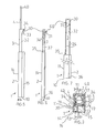
Figure 10 , there is shown a portable aerialcable lifting apparatus 1 comprising anelongate housing 2, a firsttelescopic member 3, a secondtelescopic member 4, a drive (not shown) operable at thehousing 2, and a cable-engagingmember 51 for lifting one or moreaerial cables 53. The drive comprises achain lever block 5 and apulley arrangement 60. - Referring now to
Figures 1 to 7 , a firsttelescopic member 3 is extendable from and retractable into thehousing 2, and a secondtelescopic member 4 is extendable from and retractable into the firsttelescopic member 3. - As seen in
Figure 4 , thechain lever block 5 has ablock 61, achain 16 extending over theblock 61, and alever 12 for operating theblock 61. - The
housing 2 is tubular, it has a ground-bearingbase 10 and four sidewalls 11 (only some of which have been labelled) extending therefrom. Thebase 10 is wedge-shaped and theapparatus 1 can pivot relative to the ground about an edge of the wedge.Internal sidewalls 13, 18 and elongate nylon guides 17 (only some of which have been labelled) ensure that the firsttelescopic member 3 extends and retracts correctly within the housing 2 (seeFigure 3 ). Sidewalls 13 and 18 extend from the base 10 to a position below theblock 61. Thesidewalls compartments compartments chain 16 hanging from opposite sides of theblock 61, so as to prevent entanglement of thechain 16. A liftingflange 20 extends from a lower end of the firsttelescopic member 3 betweensidewalls 13 and 18, and thechain 16 is attached to theflange 20. Theblock 5 is mounted to asidewall 11 of thehousing 2 for rotation relative thereto.Lever 12 extends from thesidewall 11. - The first
telescopic member 3 comprises a tube of rectangular cross-section and the secondtelescopic member 4 comprises a tube of circular cross-section. Thehousing 2 andtelescopic members pin 40 extends diametrically across an upper region of the secondtelescopic member 4, as seen inFigures 3 and 5 . A liftingflange 42 extends from a lower region of the secondtelescopic member 4, as seen inFigure 3 .Flange 42 prevents the secondtelescopic member 4 from rotating within the firsttelescopic member 3. - Referring now to
Figures 3 to 7 , thepulley arrangement 60 includes amain sheave 30, two additionalsmaller sheaves 31 and awire cable 34. As seen inFigures 4 and5 , anangle bracket 33 mounts sheaves 30 and 31 to afront sidewall 32 of the firsttelescopic member 3. Thefront sidewall 32 has a pair of slits (not shown) through which extend sheaves 31. Thecable 34 extends partly around each of thesheaves Figures 6 and 7 , oneend 35 of thecable 34 is attached to flange 42 and theother end 36 of thecable 34 is attached to thebase 10 of thehousing 2, so that when the firsttelescopic member 3 extends the secondtelescopic member 4 extends as well. -
Figures 8 to 10 show different types of cable-engagingmembers aerial cables 53. Eachmember cylindrical body 57 and aheadpiece 70 for engaging one ormore cables 53. A lower end of thebody 57 fits within the secondtelescopic member 4 and has aslot 54 that receivespin 40. Thepin 40 preventsmember 50 from rotating. - The
headpiece 70 ofmember 50 comprises afork 55 for lifting asingle cable 53.Member 52 differs frommember 50 in that it has asecond fork 56 of sorts (for a second cable 53) extending from thebody 57.Member 51 differs frommembers headpiece 70 has an undulatingsurface 58. Eachgroove 59 of the undulatingsurface 58 can receive acable 53. Undulatingsurface 58 enablesmultiple cables 53 to be lifted at any one time and to be kept in isolation from one another. - In use, the
apparatus 1, with thetelescopic members member telescopic member 4. Thechain lever block 5 is operated, the firsttelescopic member 3 extends from within thehousing 2 and the secondtelescopic member 4 extends from the firsttelescopic member 3. If multiple cables need to be lifted, then eithermember members 50 to 52 can be used. Thetelescopic members chain lever block 5 is locked such that thetelescopic members apparatus 1 is insulated. For instance, the cable-engagingmember telescopic member 4 can consist of a non-conductive material or can be insulated with rubber. After the truck has passed beneath the cable/s, thetelescopic members member - Once an aerial cable has been lifted, the
apparatus 1 is free standing and theapparatus 1 can, if necessary, pivot relative to the ground. The pivoting action enables theapparatus 1 to follow the movement of the lifted cable (such as when the cable sways when blown by wind) and reduces the bending moment on theapparatus 1. - The advantages of the invention include that: the apparatus can be used to raise one or more cables at any one time; since the apparatus is free standing whilst supporting the cable/s, other cables can be lifted by a single operator using additional like apparatuses; the apparatus can be used on uneven or sloping ground as it has a small ground-bearing surface; in the retracted state, the apparatus can be easily handled, transported and stored; an operator need not rely on physical strength to lift and hold a cable in the lifted position; since the apparatus is operable at ground level, an operator need not be in close proximity of an electrified cable; specialised machinery such as cherry pickers are not required; and, the apparatus can be positioned and extended in a time efficient manner with a great degree of accuracy and control.
- Whilst the above has been given by way of illustrative example of the invention, many modifications and variations may be made thereto by persons skilled in the art without departing from the scope of the claims as herein set forth.
Claims (16)
- A portable apparatus (1) for lifting at least one aerial cable, said apparatus (1) comprising: an elongate housing (2); at least a first telescopic member (3) extendible from and retractable into the elongate housing (2); a drive operable at the elongate housing (2) for extending and retracting the first telescopic member (3); and at least one cable-engaging member (50, 51, 52) positionable by the first telescopic member (3) for lifting said at least one aerial cable when the first telescopic member (3) has extended, characterised
in that a ground-bearing base (10) of said housing (2) is wedge-shaped and is adapted to pivot relative to the ground about an edge of the wedge to follow movement of the aerial cable should the aerial cable sway after having been lifted. - The apparatus (1) of claim 1 characterised in that the drive comprises a chain lever block (5) mounted to the elongate housing (2) and a chain (16) of the chain lever block (5) is attached to a lower end of the first telescopic member (3).
- The apparatus (1) of claim 2 characterised in that a block (61) of the chain lever block (5) is located within the elongate housing (2), an operative lever (12) of the chain lever block (5) extends from within the elongate housing (2) and the elongate housing (2) has separate compartments (14, 15) for containing parts of the chain (16) extending from opposite sides of the block (61).
- The apparatus (1) of claim 3 characterised in that the elongate housing (2) has internal guides (17) for the first telescopic member (3).
- The apparatus (1) of any one of claims 2 to 4 characterised in that the apparatus (1) further comprises a second telescopic member (4) extendible from and retractable into the first telescopic member (3), and the cable-engaging member (50, 51, 52) is attached to the second telescopic member (4).
- The apparatus (1) of claim 5 characterised in that the drive further comprises a pulley arrangement (60) for extending and retracting the second telescopic member (4).
- The apparatus (1) of claim 6 characterised in that the pulley arrangement (60) has at least one sheave (30) attached to an upper end of the first telescopic member (3) and a flexible tie (34) of the pulley arrangement (60) extends around the sheave (30) and has respective ends attached to a lower end of the second telescopic member (4) and to a lower end of the elongate housing (2).
- The apparatus (1) of claim 7 characterised in that when the first telescopic member (3) is raised with the chain lever block (5), the second telescopic member (4) extends about twice as far as the first telescopic member (3).
- The apparatus (1) of any one of claims 5 to 8 characterised in that the cable-engaging member (50, 51, 52) has a body (57) removably attached to an upper end of the second telescopic member (4) and a headpiece (70) extending from the body (57).
- The apparatus (1) of claim 9 characterised in that the headpiece (70) and/or body (57) has at least one fork or recess (55, 56) by which at least one said cable can be engaged and lifted.
- The apparatus (1) of claim 10 characterised in that the headpiece (70) has an undulating surface (58) and individual said cables are receivable within separate grooves (59) of the undulating surface (58).
- A method for raising at least one aerial cable, said method comprising the steps of: a) positioning a lifting apparatus (1) beneath an aerial cable, said apparatus (1) comprising: a housing (2); at least a first telescopic member (3) extendible from and retractable into the housing (2); a drive operable at the housing (2) for extending and retracting the first telescopic member (3); at least one cable-engaging member (50, 51, 52) positionable by the first telescopic member (3) for lifting said at least one aerial cable when the first telescopic member (3) has extended; and b) lifting the aerial cable, characterised in that a ground-bearing base (10) of said housing (2) is wedge-shaped and is adapted to pivot relative to the ground about an edge of the wedge to follow movement of the aerial cable should the aerial cable sway after having been lifted.
- The method of claim 12 characterised in that the apparatus (1) is free standing only whilst supporting the aerial cable.
- The method of claim 12 or claim 13 characterised in that the apparatus (1) further comprises a second telescopic member (4) extendible from and retractable into the first telescopic member (3), and the cable-engaging member (50, 51, 52) is attached to the second telescopic member (4).
- The method of any one of claims 12 to 14 characterised in that the cable-engaging member (51) lifts multiple aerial cables in isolation from one another at the same time.
- The method of any one of claims 12 to 14 characterised in that the housing (2) is tubular.
Applications Claiming Priority (3)
| Application Number | Priority Date | Filing Date | Title |
|---|---|---|---|
| AUPS084202 | 2002-03-01 | ||
| AUPS0842A AUPS084202A0 (en) | 2002-03-01 | 2002-03-01 | A lifting apparatus |
| PCT/AU2003/000256 WO2003074415A1 (en) | 2002-03-01 | 2003-03-03 | Apparatus and method for lifting aerial cables |
Publications (3)
| Publication Number | Publication Date |
|---|---|
| EP1487733A1 EP1487733A1 (en) | 2004-12-22 |
| EP1487733A4 EP1487733A4 (en) | 2005-05-25 |
| EP1487733B1 true EP1487733B1 (en) | 2009-08-12 |
Family
ID=3834441
Family Applications (1)
| Application Number | Title | Priority Date | Filing Date |
|---|---|---|---|
| EP03702219A Expired - Lifetime EP1487733B1 (en) | 2002-03-01 | 2003-03-03 | Apparatus and method for lifting aerial cables |
Country Status (15)
| Country | Link |
|---|---|
| US (1) | US7156354B2 (en) |
| EP (1) | EP1487733B1 (en) |
| JP (1) | JP4129512B2 (en) |
| KR (1) | KR100970033B1 (en) |
| AT (1) | ATE439329T1 (en) |
| AU (2) | AUPS084202A0 (en) |
| BR (1) | BRPI0308177B1 (en) |
| CA (1) | CA2477123C (en) |
| DE (1) | DE60328760D1 (en) |
| DK (1) | DK1487733T3 (en) |
| ES (1) | ES2331566T3 (en) |
| NZ (1) | NZ535352A (en) |
| PT (1) | PT1487733E (en) |
| WO (1) | WO2003074415A1 (en) |
| ZA (1) | ZA200407735B (en) |
Cited By (1)
| Publication number | Priority date | Publication date | Assignee | Title |
|---|---|---|---|---|
| CN104124642A (en) * | 2014-06-13 | 2014-10-29 | 江苏省电力公司江阴市供电公司 | Multifunctional intelligent insulation wire lifting device |
Families Citing this family (12)
| Publication number | Priority date | Publication date | Assignee | Title |
|---|---|---|---|---|
| WO2007011398A2 (en) | 2004-10-21 | 2007-01-25 | Deka Products Limited Partnership | Controllable launcher |
| CN101472432B (en) * | 2007-12-27 | 2011-11-30 | 鸿富锦精密工业(深圳)有限公司 | Adjustment mechanism |
| CN101481073B (en) * | 2008-01-09 | 2012-03-14 | 鸿富锦精密工业(深圳)有限公司 | Lifting mechanism and cylinder thereof |
| AU2009202541B2 (en) * | 2008-06-24 | 2014-05-22 | Ostaric, Mariella | Safety Lead Stand |
| US7896298B2 (en) * | 2008-07-11 | 2011-03-01 | Amg Medical Inc. | Intravenous support apparatus |
| US20100006711A1 (en) * | 2008-07-14 | 2010-01-14 | Harvey Roth | Fluid bag stand |
| US7834487B2 (en) * | 2008-09-08 | 2010-11-16 | Netz Dana A | Shorting stick for safing of high-voltage equipment |
| US8278863B2 (en) * | 2009-06-16 | 2012-10-02 | Ns Microwave | Telescoping mast |
| WO2015143147A1 (en) | 2014-03-20 | 2015-09-24 | Dominion Resources, Inc. | Shotgun stick |
| CN109713612B (en) * | 2018-12-24 | 2024-04-12 | 国家电网有限公司 | High-altitude tightening device for Dinima rope |
| CN114803931B (en) * | 2021-01-22 | 2023-12-05 | 国网智能科技股份有限公司 | Distribution network live working robot wire lifting device, method and robot |
| CN114852903B (en) * | 2022-05-24 | 2023-09-12 | 柳州欧维姆机械股份有限公司 | Control method and system for cooperative operation of jack and coiling and uncoiling device |
Family Cites Families (12)
| Publication number | Priority date | Publication date | Assignee | Title |
|---|---|---|---|---|
| US1384761A (en) * | 1920-04-14 | 1921-07-19 | James H Jessup | Cable-tie hanger |
| US1581325A (en) * | 1925-02-04 | 1926-04-20 | Russell J Sands | Extensible mast and supporting means therefor |
| US1725329A (en) * | 1927-08-19 | 1929-08-20 | Alsace S Blandford | Wall-board-handling device |
| US1748597A (en) * | 1928-03-29 | 1930-02-25 | James H Collins | Clothes tree |
| US2391536A (en) * | 1944-07-21 | 1945-12-25 | Edward M Anderson | Clothes post |
| US3788691A (en) * | 1972-04-17 | 1974-01-29 | Hastings Fiber Glass Prod Inc | Shotgun stick |
| DE2620458A1 (en) | 1976-05-08 | 1977-11-24 | Werner Chudzik | Portable telescopic rescue mast - operates first of several stages by compressed air and remaining stages by cable line assembly |
| US4079978A (en) * | 1976-12-03 | 1978-03-21 | Hastings Fiber Glass Products, Inc. | Hot stick with air cushion |
| DE2854034A1 (en) | 1978-12-14 | 1980-07-03 | Porsche Ag | Fire engine hoist mechanism - has three telescoped components, with hydraulic ram inside them for actuation by pulley cable |
| US5111907A (en) | 1990-02-20 | 1992-05-12 | Japanic Corporation | Lifting apparatus |
| DE4031105C2 (en) * | 1990-10-02 | 2000-03-09 | High Tech Geraetebau | Telescopic extendable lifting column, especially for height adjustment of a camera |
| US5533593A (en) | 1994-10-12 | 1996-07-09 | Huang; Andy C.-P. | Mobile lifter |
-
2002
- 2002-03-01 AU AUPS0842A patent/AUPS084202A0/en not_active Abandoned
-
2003
- 2003-03-03 US US10/504,858 patent/US7156354B2/en not_active Expired - Lifetime
- 2003-03-03 EP EP03702219A patent/EP1487733B1/en not_active Expired - Lifetime
- 2003-03-03 AT AT03702219T patent/ATE439329T1/en active
- 2003-03-03 ES ES03702219T patent/ES2331566T3/en not_active Expired - Lifetime
- 2003-03-03 NZ NZ535352A patent/NZ535352A/en not_active IP Right Cessation
- 2003-03-03 KR KR1020047013578A patent/KR100970033B1/en active IP Right Grant
- 2003-03-03 JP JP2003572895A patent/JP4129512B2/en not_active Expired - Fee Related
- 2003-03-03 DK DK03702219T patent/DK1487733T3/en active
- 2003-03-03 PT PT03702219T patent/PT1487733E/en unknown
- 2003-03-03 CA CA2477123A patent/CA2477123C/en not_active Expired - Fee Related
- 2003-03-03 DE DE60328760T patent/DE60328760D1/en not_active Expired - Lifetime
- 2003-03-03 BR BRPI0308177-0A patent/BRPI0308177B1/en not_active IP Right Cessation
- 2003-03-03 AU AU2003205449A patent/AU2003205449B2/en not_active Ceased
- 2003-03-03 WO PCT/AU2003/000256 patent/WO2003074415A1/en active IP Right Grant
-
2004
- 2004-09-23 ZA ZA2004/07735A patent/ZA200407735B/en unknown
Cited By (1)
| Publication number | Priority date | Publication date | Assignee | Title |
|---|---|---|---|---|
| CN104124642A (en) * | 2014-06-13 | 2014-10-29 | 江苏省电力公司江阴市供电公司 | Multifunctional intelligent insulation wire lifting device |
Also Published As
| Publication number | Publication date |
|---|---|
| ZA200407735B (en) | 2005-12-28 |
| AUPS084202A0 (en) | 2002-03-21 |
| JP2005519570A (en) | 2005-06-30 |
| AU2003205449B2 (en) | 2007-06-14 |
| DK1487733T3 (en) | 2009-12-14 |
| BR0308177A (en) | 2005-01-11 |
| EP1487733A1 (en) | 2004-12-22 |
| KR100970033B1 (en) | 2010-07-16 |
| US20050156092A1 (en) | 2005-07-21 |
| BRPI0308177B1 (en) | 2015-03-24 |
| DE60328760D1 (en) | 2009-09-24 |
| WO2003074415A1 (en) | 2003-09-12 |
| KR20040095245A (en) | 2004-11-12 |
| ES2331566T3 (en) | 2010-01-08 |
| NZ535352A (en) | 2006-01-27 |
| JP4129512B2 (en) | 2008-08-06 |
| CA2477123A1 (en) | 2003-09-12 |
| CA2477123C (en) | 2011-07-19 |
| AU2003205449A1 (en) | 2003-09-16 |
| US7156354B2 (en) | 2007-01-02 |
| EP1487733A4 (en) | 2005-05-25 |
| PT1487733E (en) | 2009-11-11 |
| ATE439329T1 (en) | 2009-08-15 |
Similar Documents
| Publication | Publication Date | Title |
|---|---|---|
| EP1487733B1 (en) | Apparatus and method for lifting aerial cables | |
| US5035336A (en) | Compact collapsible manhole cover lifter | |
| US4466506A (en) | Wire lift device for high tension electric line | |
| US6945742B2 (en) | Portable manhole cover remover | |
| US4596336A (en) | Mobile crane | |
| US4721213A (en) | Equipment and method for installing apparatus at elevated locations | |
| US6041558A (en) | Collapsible tower system for antenna or the like | |
| US4582206A (en) | Mobile aerial hoist | |
| US7520398B1 (en) | Gin hoist | |
| US10662046B1 (en) | Boom-mountable material handler | |
| US20050189527A1 (en) | Aerial cable placing machine | |
| US6616397B1 (en) | Hoist system and method of use | |
| US20040040925A1 (en) | Portable lift apparatus | |
| US10622791B2 (en) | Field-mountable winch assembly | |
| US6648570B2 (en) | Lifting and installing streetlight poles | |
| US4514939A (en) | Extensible boom with manual section stored in base | |
| AU2005203153A1 (en) | Safety system for truck loading or unloading | |
| CN216764125U (en) | Ground hoisting moving tool for construction site | |
| US4364545A (en) | Well servicing apparatus | |
| CN210285567U (en) | A multi-functional transport pole for elevator maintenance | |
| CN215160610U (en) | Lifting platform capable of being fixed and prevented from sliding in multiple directions | |
| CN212766328U (en) | Tortoise car for cable transportation | |
| EP0159543B1 (en) | Hydraulic crane aerial platform attachment | |
| JP2981615B1 (en) | Universal bogie for supporting electric pole | |
| CZ2209U1 (en) | Additional crane equipment |
Legal Events
| Date | Code | Title | Description |
|---|---|---|---|
| PUAI | Public reference made under article 153(3) epc to a published international application that has entered the european phase |
Free format text: ORIGINAL CODE: 0009012 |
|
| 17P | Request for examination filed |
Effective date: 20040916 |
|
| AK | Designated contracting states |
Kind code of ref document: A1 Designated state(s): AT BE BG CH CY CZ DE DK EE ES FI FR GB GR HU IE IT LI LU MC NL PT RO SE SI SK TR |
|
| AX | Request for extension of the european patent |
Extension state: AL LT LV MK RO |
|
| RAP1 | Party data changed (applicant data changed or rights of an application transferred) |
Owner name: MSCLE HOLDINGS PTY LTD |
|
| RIN1 | Information on inventor provided before grant (corrected) |
Inventor name: SHEPHERD, KEIRON Inventor name: CLEM, TREVOR JOHN |
|
| A4 | Supplementary search report drawn up and despatched |
Effective date: 20050408 |
|
| RIC1 | Information provided on ipc code assigned before grant |
Ipc: 7B 66F 11/00 A Ipc: 7H 02G 7/00 B Ipc: 7B 25J 1/04 B Ipc: 7H 02G 1/02 B |
|
| 17Q | First examination report despatched |
Effective date: 20071213 |
|
| GRAP | Despatch of communication of intention to grant a patent |
Free format text: ORIGINAL CODE: EPIDOSNIGR1 |
|
| GRAS | Grant fee paid |
Free format text: ORIGINAL CODE: EPIDOSNIGR3 |
|
| GRAA | (expected) grant |
Free format text: ORIGINAL CODE: 0009210 |
|
| AK | Designated contracting states |
Kind code of ref document: B1 Designated state(s): AT BE BG CH CY CZ DE DK EE ES FI FR GB GR HU IE IT LI LU MC NL PT RO SE SI SK TR |
|
| REG | Reference to a national code |
Ref country code: GB Ref legal event code: FG4D |
|
| REG | Reference to a national code |
Ref country code: CH Ref legal event code: EP |
|
| REG | Reference to a national code |
Ref country code: IE Ref legal event code: FG4D |
|
| REF | Corresponds to: |
Ref document number: 60328760 Country of ref document: DE Date of ref document: 20090924 Kind code of ref document: P |
|
| REG | Reference to a national code |
Ref country code: PT Ref legal event code: SC4A Free format text: AVAILABILITY OF NATIONAL TRANSLATION Effective date: 20091103 |
|
| REG | Reference to a national code |
Ref country code: CH Ref legal event code: NV Representative=s name: RIEDERER HASLER & PARTNER PATENTANWAELTE AG |
|
| REG | Reference to a national code |
Ref country code: SE Ref legal event code: TRGR |
|
| REG | Reference to a national code |
Ref country code: DK Ref legal event code: T3 |
|
| REG | Reference to a national code |
Ref country code: GR Ref legal event code: EP Ref document number: 20090402728 Country of ref document: GR |
|
| REG | Reference to a national code |
Ref country code: ES Ref legal event code: FG2A Ref document number: 2331566 Country of ref document: ES Kind code of ref document: T3 |
|
| PG25 | Lapsed in a contracting state [announced via postgrant information from national office to epo] |
Ref country code: SI Free format text: LAPSE BECAUSE OF FAILURE TO SUBMIT A TRANSLATION OF THE DESCRIPTION OR TO PAY THE FEE WITHIN THE PRESCRIBED TIME-LIMIT Effective date: 20090812 |
|
| REG | Reference to a national code |
Ref country code: HU Ref legal event code: AG4A Ref document number: E006775 Country of ref document: HU |
|
| PG25 | Lapsed in a contracting state [announced via postgrant information from national office to epo] |
Ref country code: BG Free format text: LAPSE BECAUSE OF FAILURE TO SUBMIT A TRANSLATION OF THE DESCRIPTION OR TO PAY THE FEE WITHIN THE PRESCRIBED TIME-LIMIT Effective date: 20091112 |
|
| PG25 | Lapsed in a contracting state [announced via postgrant information from national office to epo] |
Ref country code: RO Free format text: LAPSE BECAUSE OF FAILURE TO SUBMIT A TRANSLATION OF THE DESCRIPTION OR TO PAY THE FEE WITHIN THE PRESCRIBED TIME-LIMIT Effective date: 20090812 Ref country code: EE Free format text: LAPSE BECAUSE OF FAILURE TO SUBMIT A TRANSLATION OF THE DESCRIPTION OR TO PAY THE FEE WITHIN THE PRESCRIBED TIME-LIMIT Effective date: 20090812 |
|
| PG25 | Lapsed in a contracting state [announced via postgrant information from national office to epo] |
Ref country code: SK Free format text: LAPSE BECAUSE OF FAILURE TO SUBMIT A TRANSLATION OF THE DESCRIPTION OR TO PAY THE FEE WITHIN THE PRESCRIBED TIME-LIMIT Effective date: 20090812 |
|
| PLBE | No opposition filed within time limit |
Free format text: ORIGINAL CODE: 0009261 |
|
| STAA | Information on the status of an ep patent application or granted ep patent |
Free format text: STATUS: NO OPPOSITION FILED WITHIN TIME LIMIT |
|
| 26N | No opposition filed |
Effective date: 20100517 |
|
| PG25 | Lapsed in a contracting state [announced via postgrant information from national office to epo] |
Ref country code: MC Free format text: LAPSE BECAUSE OF NON-PAYMENT OF DUE FEES Effective date: 20100331 |
|
| PG25 | Lapsed in a contracting state [announced via postgrant information from national office to epo] |
Ref country code: CY Free format text: LAPSE BECAUSE OF FAILURE TO SUBMIT A TRANSLATION OF THE DESCRIPTION OR TO PAY THE FEE WITHIN THE PRESCRIBED TIME-LIMIT Effective date: 20090812 |
|
| PG25 | Lapsed in a contracting state [announced via postgrant information from national office to epo] |
Ref country code: LU Free format text: LAPSE BECAUSE OF NON-PAYMENT OF DUE FEES Effective date: 20100303 |
|
| PG25 | Lapsed in a contracting state [announced via postgrant information from national office to epo] |
Ref country code: TR Free format text: LAPSE BECAUSE OF FAILURE TO SUBMIT A TRANSLATION OF THE DESCRIPTION OR TO PAY THE FEE WITHIN THE PRESCRIBED TIME-LIMIT Effective date: 20090812 |
|
| REG | Reference to a national code |
Ref country code: FR Ref legal event code: PLFP Year of fee payment: 14 |
|
| REG | Reference to a national code |
Ref country code: FR Ref legal event code: PLFP Year of fee payment: 15 |
|
| PGFP | Annual fee paid to national office [announced via postgrant information from national office to epo] |
Ref country code: NL Payment date: 20170315 Year of fee payment: 15 Ref country code: GR Payment date: 20170327 Year of fee payment: 15 Ref country code: CH Payment date: 20170320 Year of fee payment: 15 |
|
| PGFP | Annual fee paid to national office [announced via postgrant information from national office to epo] |
Ref country code: IE Payment date: 20170320 Year of fee payment: 15 Ref country code: AT Payment date: 20170327 Year of fee payment: 15 Ref country code: DK Payment date: 20170323 Year of fee payment: 15 Ref country code: PT Payment date: 20170302 Year of fee payment: 15 Ref country code: HU Payment date: 20170302 Year of fee payment: 15 Ref country code: BE Payment date: 20170315 Year of fee payment: 15 |
|
| PGFP | Annual fee paid to national office [announced via postgrant information from national office to epo] |
Ref country code: IT Payment date: 20170321 Year of fee payment: 15 |
|
| PGFP | Annual fee paid to national office [announced via postgrant information from national office to epo] |
Ref country code: ES Payment date: 20170328 Year of fee payment: 15 |
|
| REG | Reference to a national code |
Ref country code: FR Ref legal event code: PLFP Year of fee payment: 16 |
|
| REG | Reference to a national code |
Ref country code: DK Ref legal event code: EBP Effective date: 20180331 |
|
| PG25 | Lapsed in a contracting state [announced via postgrant information from national office to epo] |
Ref country code: PT Free format text: LAPSE BECAUSE OF NON-PAYMENT OF DUE FEES Effective date: 20180903 |
|
| REG | Reference to a national code |
Ref country code: CH Ref legal event code: PL |
|
| REG | Reference to a national code |
Ref country code: NL Ref legal event code: MM Effective date: 20180401 |
|
| REG | Reference to a national code |
Ref country code: AT Ref legal event code: MM01 Ref document number: 439329 Country of ref document: AT Kind code of ref document: T Effective date: 20180303 |
|
| REG | Reference to a national code |
Ref country code: BE Ref legal event code: MM Effective date: 20180331 |
|
| REG | Reference to a national code |
Ref country code: IE Ref legal event code: MM4A |
|
| PG25 | Lapsed in a contracting state [announced via postgrant information from national office to epo] |
Ref country code: NL Free format text: LAPSE BECAUSE OF NON-PAYMENT OF DUE FEES Effective date: 20180401 |
|
| PG25 | Lapsed in a contracting state [announced via postgrant information from national office to epo] |
Ref country code: HU Free format text: LAPSE BECAUSE OF NON-PAYMENT OF DUE FEES Effective date: 20180304 Ref country code: GR Free format text: LAPSE BECAUSE OF NON-PAYMENT OF DUE FEES Effective date: 20181003 Ref country code: IE Free format text: LAPSE BECAUSE OF NON-PAYMENT OF DUE FEES Effective date: 20180303 Ref country code: AT Free format text: LAPSE BECAUSE OF NON-PAYMENT OF DUE FEES Effective date: 20180303 |
|
| PG25 | Lapsed in a contracting state [announced via postgrant information from national office to epo] |
Ref country code: BE Free format text: LAPSE BECAUSE OF NON-PAYMENT OF DUE FEES Effective date: 20180331 Ref country code: CH Free format text: LAPSE BECAUSE OF NON-PAYMENT OF DUE FEES Effective date: 20180331 Ref country code: LI Free format text: LAPSE BECAUSE OF NON-PAYMENT OF DUE FEES Effective date: 20180331 Ref country code: IT Free format text: LAPSE BECAUSE OF NON-PAYMENT OF DUE FEES Effective date: 20180303 |
|
| PG25 | Lapsed in a contracting state [announced via postgrant information from national office to epo] |
Ref country code: DK Free format text: LAPSE BECAUSE OF NON-PAYMENT OF DUE FEES Effective date: 20180331 |
|
| REG | Reference to a national code |
Ref country code: ES Ref legal event code: FD2A Effective date: 20190904 |
|
| PG25 | Lapsed in a contracting state [announced via postgrant information from national office to epo] |
Ref country code: ES Free format text: LAPSE BECAUSE OF NON-PAYMENT OF DUE FEES Effective date: 20180304 |
|
| PGFP | Annual fee paid to national office [announced via postgrant information from national office to epo] |
Ref country code: FI Payment date: 20200309 Year of fee payment: 18 Ref country code: SE Payment date: 20200310 Year of fee payment: 18 Ref country code: DE Payment date: 20200218 Year of fee payment: 18 Ref country code: GB Payment date: 20200219 Year of fee payment: 18 |
|
| PGFP | Annual fee paid to national office [announced via postgrant information from national office to epo] |
Ref country code: CZ Payment date: 20200218 Year of fee payment: 18 |
|
| PGFP | Annual fee paid to national office [announced via postgrant information from national office to epo] |
Ref country code: FR Payment date: 20200214 Year of fee payment: 18 |
|
| REG | Reference to a national code |
Ref country code: DE Ref legal event code: R119 Ref document number: 60328760 Country of ref document: DE |
|
| REG | Reference to a national code |
Ref country code: FI Ref legal event code: MAE |
|
| PG25 | Lapsed in a contracting state [announced via postgrant information from national office to epo] |
Ref country code: CZ Free format text: LAPSE BECAUSE OF NON-PAYMENT OF DUE FEES Effective date: 20210303 Ref country code: FI Free format text: LAPSE BECAUSE OF NON-PAYMENT OF DUE FEES Effective date: 20210303 |
|
| GBPC | Gb: european patent ceased through non-payment of renewal fee |
Effective date: 20210303 |
|
| PG25 | Lapsed in a contracting state [announced via postgrant information from national office to epo] |
Ref country code: SE Free format text: LAPSE BECAUSE OF NON-PAYMENT OF DUE FEES Effective date: 20210304 Ref country code: DE Free format text: LAPSE BECAUSE OF NON-PAYMENT OF DUE FEES Effective date: 20211001 Ref country code: FR Free format text: LAPSE BECAUSE OF NON-PAYMENT OF DUE FEES Effective date: 20210331 Ref country code: GB Free format text: LAPSE BECAUSE OF NON-PAYMENT OF DUE FEES Effective date: 20210303 |