JP4129512B2 - Apparatus and method for lifting aerial cables - Google Patents
Apparatus and method for lifting aerial cables Download PDFInfo
- Publication number
- JP4129512B2 JP4129512B2 JP2003572895A JP2003572895A JP4129512B2 JP 4129512 B2 JP4129512 B2 JP 4129512B2 JP 2003572895 A JP2003572895 A JP 2003572895A JP 2003572895 A JP2003572895 A JP 2003572895A JP 4129512 B2 JP4129512 B2 JP 4129512B2
- Authority
- JP
- Japan
- Prior art keywords
- housing
- cable
- telescopic
- elastic member
- telescopic member
- Prior art date
- Legal status (The legal status is an assumption and is not a legal conclusion. Google has not performed a legal analysis and makes no representation as to the accuracy of the status listed.)
- Expired - Fee Related
Links
Images


Classifications
-
- B—PERFORMING OPERATIONS; TRANSPORTING
- B66—HOISTING; LIFTING; HAULING
- B66F—HOISTING, LIFTING, HAULING OR PUSHING, NOT OTHERWISE PROVIDED FOR, e.g. DEVICES WHICH APPLY A LIFTING OR PUSHING FORCE DIRECTLY TO THE SURFACE OF A LOAD
- B66F3/00—Devices, e.g. jacks, adapted for uninterrupted lifting of loads
- B66F3/24—Devices, e.g. jacks, adapted for uninterrupted lifting of loads fluid-pressure operated
- B66F3/25—Constructional features
- B66F3/26—Adaptations or arrangements of pistons
- B66F3/28—Adaptations or arrangements of pistons telescopic
-
- H—ELECTRICITY
- H02—GENERATION; CONVERSION OR DISTRIBUTION OF ELECTRIC POWER
- H02G—INSTALLATION OF ELECTRIC CABLES OR LINES, OR OF COMBINED OPTICAL AND ELECTRIC CABLES OR LINES
- H02G1/00—Methods or apparatus specially adapted for installing, maintaining, repairing or dismantling electric cables or lines
- H02G1/02—Methods or apparatus specially adapted for installing, maintaining, repairing or dismantling electric cables or lines for overhead lines or cables
-
- B—PERFORMING OPERATIONS; TRANSPORTING
- B66—HOISTING; LIFTING; HAULING
- B66F—HOISTING, LIFTING, HAULING OR PUSHING, NOT OTHERWISE PROVIDED FOR, e.g. DEVICES WHICH APPLY A LIFTING OR PUSHING FORCE DIRECTLY TO THE SURFACE OF A LOAD
- B66F11/00—Lifting devices specially adapted for particular uses not otherwise provided for
-
- H—ELECTRICITY
- H02—GENERATION; CONVERSION OR DISTRIBUTION OF ELECTRIC POWER
- H02G—INSTALLATION OF ELECTRIC CABLES OR LINES, OR OF COMBINED OPTICAL AND ELECTRIC CABLES OR LINES
- H02G7/00—Overhead installations of electric lines or cables
-
- Y—GENERAL TAGGING OF NEW TECHNOLOGICAL DEVELOPMENTS; GENERAL TAGGING OF CROSS-SECTIONAL TECHNOLOGIES SPANNING OVER SEVERAL SECTIONS OF THE IPC; TECHNICAL SUBJECTS COVERED BY FORMER USPC CROSS-REFERENCE ART COLLECTIONS [XRACs] AND DIGESTS
- Y10—TECHNICAL SUBJECTS COVERED BY FORMER USPC
- Y10T—TECHNICAL SUBJECTS COVERED BY FORMER US CLASSIFICATION
- Y10T403/00—Joints and connections
- Y10T403/32—Articulated members
- Y10T403/32254—Lockable at fixed position
- Y10T403/32467—Telescoping members
Abstract
Description
本発明は、頭上の電化ケーブルのような空中ケーブルを上げるための装置及び方法に関する。特に、本発明は、1本又はそれ以上の空中ケーブルを上げるための可搬式の伸縮装置に関する。 The present invention relates to an apparatus and method for raising an aerial cable, such as an overhead electrical cable. In particular, the invention relates to a portable telescopic device for raising one or more aerial cables.
特大の荷物を積載しているトラックが遭遇する一般的な問題は、道に沿ったトラックの通行が頭上の電化ケーブル又は他の空中ケーブルによって妨げられることである。この問題を克服するための標準的な作業は、油圧装置(すなわち「チェリーピッカー」)を使用してケーブルを持ち上げるか、又は「リフトスティック」を手に持って、ケーブルを手動で持ち上げて保持することである。特大の荷物がケーブルの下を通過するまで、2つ以上のチェリーピッカーと2人以上の作業者が、持ち上げ位置のケーブルを持ち上げて、保持するために必要となる。複数の空中ケーブルがある場所では、ケーブルを持ち上げるために必要な作業者とチェリーピッカーの数は、一般的には増加する。 A common problem encountered with trucks carrying oversized luggage is that truck traffic along the road is obstructed by overhead electrical cables or other aerial cables. Standard work to overcome this problem is to lift the cable using a hydraulic device (ie, a “cherry picker”), or hold the “lift stick” in hand to lift and hold the cable manually That is. Two or more cherry pickers and two or more workers are required to lift and hold the cable in the lift position until the oversized baggage passes under the cable. Where there are multiple aerial cables, the number of workers and cherry pickers required to lift the cables generally increases.
上記作業の欠点のいくつかは、次の通りである:長時間ケーブルを物理的に持ち上げて保持する作業者が必要であり、ケーブルは30kgもの重さにもなる;チェリーピッカーは、チェリーピッカー内部のバケットから一般的には操作されるため、作業者は、危険な通電中のケーブルの近くに位置することがある;そして、特に多くの作業者及びチェリーピッカーが必要な場合、作業は、高価で時間のかかるものとなる。 Some of the disadvantages of the above work are as follows: requires an operator to physically lift and hold the cable for a long time, and the cable can weigh as much as 30 kg; the cherry picker is inside the cherry picker The operator may be located near a dangerously energized cable because it is typically operated from a large bucket; and the work is expensive, especially when many workers and cherry pickers are required It will take time.
本発明は、上述した欠点の少なくとも一つを最小化又は克服する、空中ケーブルを持ち上げる可搬式の装置及び方法を提供することであり、又は公衆に有用若しくは商業的な選択を提供することを目的とする。 The present invention aims to provide a portable device and method for lifting an aerial cable that minimizes or overcomes at least one of the above-mentioned drawbacks, or aims to provide a useful or commercial choice to the public. And
本発明の第一の形態によれば、
少なくとも1本の空中ケーブルを持ち上げるための可搬式の装置であって、
細長いハウジングと、
少なくとも細長いハウジングから拡張可能で、該ハウジングへ格納可能な第1の伸縮部材と、
第1の伸縮部材を展開し、格納するための細長いハウジングで操作可能な駆動手段と、
第1の伸縮部材が展開したときに、少なくとも1本の空中ケーブルを持ち上げるために第1の伸縮部材によって位置決めされる、少なくとも1本のケーブル連結部材とを含み、
持ち上げられた後で空中ケーブルが揺れれば、空中ケーブルの運動をたどるように、前記ハウジングが地面に対して軸回転するよう構成されている装置が提供される。
According to the first aspect of the present invention,
A portable device for lifting at least one aerial cable,
An elongated housing;
A first telescopic member expandable from at least the elongated housing and retractable into the housing;
Drive means operable with an elongated housing for deploying and storing the first telescopic member;
When deployed the first elastic member is positioned by the first telescopic member for lifting at least one aerial cable, it sees contains at least one cable connecting member,
If the aerial cable swings after being lifted, a device is provided in which the housing is configured to pivot relative to the ground so as to follow the movement of the aerial cable .
駆動手段にはいかなる適切な種類のものも用いることができる。駆動手段には、例えば、電動モーター、油圧モーター、エンジン、チェーンレバーブロック、手動ウインチ、昇降機、起重機又はこれら装置の適切な組み合わせが含まれる。 Any suitable type of drive means can be used. The drive means includes, for example, an electric motor, a hydraulic motor, an engine, a chain lever block, a manual winch, a lift, a hoist or a suitable combination of these devices.
好ましくは、駆動手段は、チェーンレバーブロックを有する。チェーンレバーブロックは、細長いハウジングに取り付けることが可能であり、チェーンレバーブロックのチェーンは、第1の伸縮部材の下端に取り付けることができる。 Preferably, the driving means has a chain lever block. The chain lever block can be attached to an elongated housing, and the chain of the chain lever block can be attached to the lower end of the first elastic member.
チェーンレバーブロックのブロックは、細長いハウジングの内部に位置することができ、チェーンレバーブロックの操作レバーは、細長いハウジング内から展開することができる。細長いハウジングは、チェーンのもつれを防止するために、ブロックの両側から懸架するチェーンを含む部品のための、着脱可能なコンパートメントを有することができる。 The block of the chain lever block can be located inside the elongated housing, and the operating lever of the chain lever block can be deployed from within the elongated housing. The elongate housing can have a detachable compartment for parts including the chain suspended from both sides of the block to prevent chain entanglement.
細長いハウジングは、いかなる適切なサイズ、形状及び構造であってもよい。細長いハウジングは、好ましくは長方形の横断面である管である。細長いハウジングは、第1の伸縮部材が正確に展開し、格納することを確実にするために、内部壁又はガイドを有することができる。 The elongate housing may be any suitable size, shape and structure. The elongated housing is a tube that is preferably rectangular in cross section. The elongate housing can have an internal wall or guide to ensure that the first telescopic member is correctly deployed and retracted.
空中ケーブルを支持する間、装置は固定されておらず、ケーブルの運動をたどるために地面に対応して軸回転することができる。細長いハウジングの支柱底面は、軸回転するために構成されることが好ましい。支柱底面は、いかなる適切な形状、サイズ及び構造であってもよい。支柱底面はくさび形であり、装置はくさびの端付近で地面に対して軸回転できることが好ましい。 While supporting the aerial cable, the device is not fixed and can pivot relative to the ground to follow the movement of the cable. The bottom surface of the elongated housing is preferably configured for axial rotation. The bottom of the column may be any suitable shape, size and structure. Preferably, the bottom of the column is wedge-shaped and the device can be pivoted relative to the ground near the end of the wedge.
装置は、任意の適当な数の伸縮部材を含むことができる。本発明の好ましい形態において、装置は第1の伸縮部材から展開可能で、第1の伸縮部材内に格納可能な第2の伸縮部材を有し、ケーブル連結部材は、第2の伸縮部材に取り付けられる。 The device can include any suitable number of telescopic members. In a preferred embodiment of the present invention, the device can be deployed from the first elastic member, has a second elastic member that can be stored in the first elastic member, and the cable connecting member is attached to the second elastic member. It is done.
第1及び第2の伸縮部材は、いかなる適切なサイズ、形状及び構造であってもよい。好ましくは、第1の伸縮部材は、長方形の横断面の管を含み、第2の伸縮部材は、環状の横断面を有する。 The first and second elastic members may be any suitable size, shape and structure. Preferably, the first elastic member includes a tube having a rectangular cross section, and the second elastic member has an annular cross section.
好ましくは、駆動手段は、さらに第2の伸縮部材を展開し、格納するためのプーリを有する。プーリは、第1の伸縮部材の上端部に取り付けられる、少なくとも一つのシーブを有することができ、プーリの伸縮自在な連結部材は、シーブの周辺に展開することが可能であり、第2の伸縮部材の下端及び細長いハウジングの下端にそれぞれ取り付けられる端部を有する。 Preferably, the driving means further includes a pulley for expanding and storing the second elastic member. The pulley can have at least one sheave attached to the upper end of the first telescopic member, and the telescopic connection member of the pulley can be deployed around the sheave and the second telescopic member. Ends are attached to the lower end of the member and the lower end of the elongated housing, respectively.
この構成では、第1伸縮部材がチェーンレバーブロックによって持ち上がるときに、第2の伸縮部材は、第1の伸縮部材の約2倍展開する。伸縮自在の連結部材は、例えば、ワイヤーケーブル又はコードである。 In this configuration, when the first elastic member is lifted by the chain lever block, the second elastic member expands about twice as much as the first elastic member. The telescopic connection member is, for example, a wire cable or a cord.
装置は、チェーンレバーブロックが最初に操作されない限り、第1及び第2の伸縮部材が展開し、又は格納することができないことを確実にするためのロック機構を有することができる。あらゆる適切な種類のロック機構を用いることが可能である。 The device can have a locking mechanism to ensure that the first and second telescopic members cannot be deployed or retracted unless the chain lever block is first operated. Any suitable type of locking mechanism can be used.
ケーブル連結部材は、いかなる適切なサイズ、形状及び構造であってもよい。装置がどれくらいの数の伸縮部材を有するかに依存して、ケーブル連結部材は、第2の伸縮部材又は第1の伸縮部材に取り付けることができる。ケーブル連結部材は、いかなる適切な方法によっても取り付けることが可能である。装置は、適当な数のケーブル連結部材を有することができる。 The cable coupling member may be any suitable size, shape and structure. Depending on how many telescopic members the device has, the cable connection member can be attached to the second telescopic member or the first telescopic member. The cable connecting member can be attached by any suitable method. The device can have any suitable number of cable coupling members.
ケーブル連結部材は、好ましくはボデー及びボデーから展開する頭部を有する。ボデーの下端は、第2の伸縮部材の上端部に、着脱自在に取り付けることが可能である。ボデーは、ケーブル連結部材及び伸縮部材が、互いに関連して回転することができないように取り付けることが好ましい。このことは、例えば、第2の伸縮部材及びボデーにピン及びスロット配列、凸縁及び溝型配列、又は差し込みピン配列を設置することによって達成することが可能である。 The cable connecting member preferably has a body and a head extending from the body. The lower end of the body can be detachably attached to the upper end portion of the second elastic member. The body is preferably attached so that the cable connecting member and the elastic member cannot rotate relative to each other. This can be achieved, for example, by installing a pin and slot arrangement, a convex and groove arrangement, or a bayonet arrangement on the second telescopic member and body.
ケーブル連結部材は、ケーブルがかみ合い、持ち上げることが可能である二又、尖った先端部、溝、チャンネル、凹部又は他のいかなる適切な構造も有することができる。装置は、ケーブル連結部材が複数の二又、溝等を有することができる場合に、いかなるときも複数のケーブルを持ち上げるために用いることができる。二又、溝等は、頭部及び/又はボデーに位置することができる。 The cable connection member may have a bifurcated tip, groove, channel, recess or any other suitable structure that allows the cable to engage and lift. The device can be used to lift a plurality of cables at any time when the cable connecting member can have a plurality of bifurcated grooves or the like. In addition, the groove or the like can be located in the head and / or body.
本発明の一実施例において、頭部は、熊手の作業端によく似た波形表面を有し、個々のケーブルは、波形表面の別個の溝の内部に保持されることができる。この構成では、持ち上げられるときに、ケーブルは互いに分離して保持されることができる。本発明の別の実施例において、頭部及び/又はボデーは、少なくとも1本のケーブルをかみ合わせて持ち上げるための、少なくとも一つの二又又は溝を有する。 In one embodiment of the invention, the head has a corrugated surface that resembles the working end of a rake, and individual cables can be held within separate grooves in the corrugated surface. In this configuration, the cables can be held separate from each other when lifted. In another embodiment of the invention, the head and / or body has at least one bifurcated or groove for engaging and lifting at least one cable.
装置は、コンパクトで軽量であることが好ましい。装置は、いかなる適切な材料、例えば、金属、プラスチック材及び複合材のような材料から構成されることができる。電化ケーブルを持ち上げるために使われるときに、装置又はその部品は、絶縁することができる。例えば、ケーブル連結部材を絶縁することができる。 The device is preferably compact and lightweight. The device can be constructed from any suitable material, such as metals, plastic materials and composites. When used to lift an electrified cable, the device or its components can be insulated. For example, the cable connecting member can be insulated.
本発明の第二の形態によれば、
少なくとも1本の空中ケーブルを持ち上げるための方法であって、
a) ハウジングと、ハウジングから展開可能で、ハウジング内に格納可能な少なくとも一つの第1の伸縮部材と、第1の伸縮部材を展開し、格納するためにハウジングで操作可能な駆動手段と、第1の伸縮部材が展開したときに、少なくとも1本の空中ケーブルを持ち上げるために第1の伸縮部材によって位置決めすることができる、少なくとも一つのケーブル連結部材とを含む持ち上げ装置を空中ケーブルの下へ配置すること、及び
b)空中ケーブルを持ち上げ、このとき、持ち上げられた後で空中ケーブルが揺れれば、空中ケーブルの運動をたどるように、前記ハウジングが地面に対して軸回転するよう構成されていること、のステップを含む方法が提供される。
By the second embodiment of the present invention lever,
A method for lifting at least one aerial cable comprising:
a) a housing, at least one first telescopic member deployable from the housing and retractable within the housing, drive means operable on the housing to deploy and store the first telescopic member; A lifting device including at least one cable coupling member, which can be positioned by the first telescopic member to lift at least one aerial cable when one telescopic member is deployed, is disposed below the aerial cable. It is, and b) lifting the aerial cable, this time, if Yurere aerial cable after being lifted, to follow movement of the aerial cable, that is adapted to the housing pivots with respect to the ground A method comprising the steps of:
ハウジングは、いかなる適切なサイズ、形状及び構造であってもよい。ハウジングは、スタンドの形であってもよい。空中ケーブルを支持する間、装置は固定されておらず、ケーブルの運動に連動するために地面に対して軸回転することができる。ハウジングは、好ましくは管状である。 The housing may be any suitable size, shape and structure. The housing may be in the form of a stand. While supporting the aerial cable, the device is not fixed and can pivot about the ground to interlock with the movement of the cable. The housing is preferably tubular.
装置は、好ましくは、第1の伸縮部材から展開可能で、第1の伸縮部材に格納可能な第2の伸縮部材をさらに含み、ケーブル連結部材は、第2の伸縮部材に取り付けられる。 The apparatus preferably further includes a second elastic member that is deployable from the first elastic member and can be stored in the first elastic member, and the cable connecting member is attached to the second elastic member.
ケーブル連結部材は、好ましくは、複数の空中ケーブルを同時に、互いに分離して持ち上げることができる。 The cable connection member is preferably capable of lifting a plurality of aerial cables simultaneously and separated from each other.
装置は、本発明の第1の形態に関して記載される他の特徴を有することもできる。 The device can also have other features as described for the first aspect of the invention.
本発明を実施するための最良の形態を、以下、図面を参照しながら説明する。全ての図面において、符号は、対応する部品に言及する。 The best mode for carrying out the present invention will be described below with reference to the drawings. In all the drawings, reference numerals refer to corresponding parts.
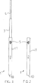
最初に、図10に関連して、細長いハウジング2、第1の伸縮部材3、第2の伸縮の部材4、ハウジング2で操作可能な駆動手段(図示せず)、及び1本又はそれ以上の空中ケーブル53を持ち上げるためのケーブル連結部材51を具備する、可搬式の空中ケーブル持ち上げ装置1が示される。駆動手段5は、チェーンレバーブロック5とプーリ60とを具備している。
First, with reference to FIG. 10, an
次に、図1乃至7を参照して、第1の伸縮部材3は、ハウジング2から展開可能で、ハウジング2に格納可能であり、第2の伸縮部材4は、第1の伸縮部材3から展開可能であり、第1の伸縮部材3に格納可能である。
Next, referring to FIGS. 1 to 7, the first
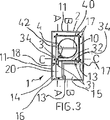
図4に示すように、チェーンレバーブロック5は、ブロック61、ブロック61を通じて展開するチェーン16、及びブロック61を動かすためのレバー12を有する。
As shown in FIG. 4, the
ハウジング2は、管状であり、支柱底面10、及びそこから延びている4つの側壁11(それらのうち、いくつかのみラベルをつけられる)を有する。
The
支柱底面10は、くさび形であり、装置1は、くさびの端について地面に対応して軸回転することができる。内部側壁13、18及び細長いナイロンガイド17(それらのうち、いくつかのみラベルをつけられる)は、第1の伸縮部材3がハウジング2の内部で展開し、格納することを確実にする(図3を参照)。側壁13及び18は、支柱底面10からブロック61の下の位置まで展開する。側壁11、13、18は、共に2つのコンパートメント14及び15を提供する。コンパートメント14及び15は、チェーン16のもつれを防止するために、ブロック61の両側から懸架しているチェーン16の一部を集めて、収容する。持ち上げフランジ20は、側壁13及び18間にある第1の伸縮部材3の下端から展開し、チェーン16は、フランジ20に取り付けられる。ブロック5は、それに対する軸回転のために、ハウジング2の側壁11に設置される。レバー12は、側壁11から展開する。
The
第1の伸縮部材3は、長方形の横断面を有する管を有し、第2の伸縮部材4は、環状の横断面の管を有する。ハウジング2及び伸縮部材3、4は、荷重下で載置されても曲がらないアルミニウム又は複合材(例えば、ケブラー(登録商標))から構成される。図3及び5に示すように、ピン40は、第2の伸縮部材4の上部域をまっすぐに横切る。図3に示すように、持ち上げフランジ42は、第2の伸縮部材4の下部域から展開する。フランジ42は、第2の伸縮部材4が、第1の伸縮部材3の内部で回転するのを防止する。
The first
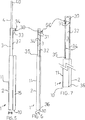
次に、図3乃至7を参照して、プーリ60は、主要シーブ30、二つの補助的な小型シーブ31及びワイヤーケーブル34を含む。図4及び5に示すように、アングルブラケット33は、第1の伸縮部材3の前部側壁32にシーブ30及び31を取り付ける。前部側壁32は、シーブ31を展開する一対のスリット(図示せず)を有する。ケーブル34は、各々のシーブ30、31及びスリット周辺で部分的に展開する。図6及び7に示すように、ケーブル34の一端35は、フランジ42に取り付けられ、ケーブル34の他端36は、ハウジング2の支柱底面10に取り付けられ、その結果、第1の伸縮部材3が展開するときに、第2の伸縮部材4も同様に展開する。
3 to 7, the
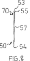
図8乃至10は、空中ケーブル53を持ち上げるためのケーブル連結部材50、51、52の異なる種類を示す。各々の部材50、51、52は、円筒形ボデー57及び1本1本又はそれ以上のケーブル53をかみ合わせるための頭部70から基本的に構成される。ボデー57の下端は、第2の伸縮部材4の内部で嵌合し、ピン40を保持する溝穴54を有する。ピン40は、部材50が回転するのを防止する。
8 to 10 show different types of
部材50の頭部70は、単独のケーブル53を持ち上げるための二又55を有する。ボデー57から展開する(第2のケーブル53のための)第2の二又56を有するという点で、部材52は、部材50と異なる。その頭部70が波形表面58を有するという点で、部材51は、部材50及び52と異なる。波形表面58の各々の溝59は、ケーブル53を保持することができる。
The
波形表面58は、複数のケーブル53がいかなるときにも持ち上げられて、互いに分離された状態に維持されることを可能にする。
The
使用において、伸縮部材3、4を完全に格納した装置1は、持ち上げることを必要とする1本又はそれ以上の空中ケーブル(例えば、頭上の電線)の下に配置され、その結果、例えば、特大の荷物を積載しているトラックは、その下を通過できる。適切なケーブル連結部材50、51、52は、第2の伸縮部材4に取り付けられる。チェーンレバーブロック5が操作されると、第1の伸縮部材3は、ハウジング2内部から展開し、第2の伸縮部材4は、第1の伸縮部材3から展開する。複数のケーブルを持ち上げることが必要な場合、部材51又は52のいずれかが使用される。1本のケーブルを持ち上げることが必要な場合、部材50乃至52のいずれか一つが使用される。特大の荷物の頂部とケーブルの間に充分な隙間が存在する間、伸縮部材3、4は展開する。伸縮部材3、4が偶然に格納されることができないように、チェーンレバーブロック5は、ロックされる。電化ケーブルを持ち上げたならば、装置1は、絶縁される。例えば、ケーブル連結部材50、51、52及び/又は第2の伸縮部材4は、不導体材料から構成するか、又はゴムにより絶縁することができる。
In use, the
トラックがケーブルの下を通過した後、伸縮部材3、4は格納され、部材50、51、52は、取り外してもよい。
After the truck passes under the cable, the
一旦空中ケーブルが持ち上げられると、装置1は固定されず、装置1は必要に応じて、地面に対して軸回転することができる。軸回転作用は、装置1が持ち上げられたケーブル(例えば、ケーブルに風が吹きつけられて揺れているような)の動きをたどることを可能とし、装置1にかかる曲げモーメントを減少させる。
Once the aerial cable is lifted, the
本発明の利点には、以下の様なことが含まれる。装置は、いかなるときも1本又はそれ以上のケーブルを持ち上げるために用いることができる。ケーブルを保持する間、装置が固定されていないため、他のケーブルを、追加の同類装置を使用している単独の作業者によって持ち上げることが可能である。小さな支柱底面を有するために、装置は平坦でない又は傾斜した土地でも使用することができる。格納された状態で、装置を容易に扱い、移動し、保管することができる。持ち上げ状態において、作業者は、ケーブルを持ち上げて、保持するために体力を要しない。装置が地上で操作可能であるため、作業者が電化ケーブルの付近にいる必要がない。チェリーピッカーのような専門機械が必要ない。精度及び制御の程度が高く、時間効率的な方法で装置を配置し、展開することができる。 The advantages of the present invention include the following. The device can be used to lift one or more cables at any time. Since the device is not secured while holding the cable, other cables can be lifted by a single operator using additional like devices. Due to the small strut bottom, the device can be used even on uneven or sloping land. In the stored state, the device can be easily handled, moved and stored. In the lifted state, the operator does not need physical strength to lift and hold the cable. Since the device can be operated on the ground, there is no need for an operator to be near the electrified cable. There is no need for specialized machines such as cherry pickers. Devices can be deployed and deployed in a time efficient manner with high accuracy and control.
上記が本発明の実施例として与えられる一方、本願明細書において述べられるような本発明の広い目的及び範囲から逸脱することなく、多くの修正及び変更が当業者によってなされるであろう。 While the above is provided by way of example of the invention, many modifications and changes will be made by those skilled in the art without departing from the broad purpose and scope of the invention as described herein.
Claims (18)
細長いハウジングと、
少なくとも細長いハウジングから拡張可能で、該ハウジングへ格納可能な第1の伸縮部材と、
第1の伸縮部材を展開し、格納するための細長いハウジングで操作可能な駆動手段と、
第1の伸縮部材が展開したときに、少なくとも1本の空中ケーブルを持ち上げるために第1の伸縮部材によって位置決めされる、少なくとも1本のケーブル連結部材とを含み、
持ち上げられた後で空中ケーブルが揺れれば、空中ケーブルの運動をたどるように、前記ハウジングが地面に対して軸回転するよう構成されている装置。A portable device for lifting at least one aerial cable,
An elongated housing;
A first telescopic member expandable from at least the elongated housing and retractable into the housing;
Drive means operable with an elongated housing for deploying and storing the first telescopic member;
When deployed the first elastic member, is positioned by the first telescopic member for lifting at least one aerial cable, it sees contains at least one cable connecting member,
An apparatus configured to pivot the housing relative to the ground to follow the movement of the aerial cable if the aerial cable swings after being lifted .
前記ブロックは前記細長いハウジングに取り付けられており、前記チェーンは第1の伸縮部材の下端に取り付けられている請求項1に記載の装置。The drive means has a chain lever block comprising a block, a chain and an operating lever;
Said block is attached to said elongated housing, said chain device according to claim 1 is attached, et al is to the lower end of the first telescopic member.
チェーンレバーブロックの操作レバーが細長いハウジング内から伸び、細長いハウジングがブロックの両側から懸架しているチェーン部分を含む、着脱可能なコンパートメントを有する請求項2に記載の装置。The chain lever block block is located inside the elongated housing,
The apparatus of claim 2 having a removable compartment including a chain portion in which the operating lever of the chain lever block extends from within the elongated housing, the elongated housing being suspended from both sides of the block.
a) ハウジングと、ハウジングから展開可能で、ハウジング内に格納可能な少なくとも一つの第1の伸縮部材と、第1の伸縮部材を展開し、格納するためにハウジングで操作可能な駆動手段と、第1の伸縮部材が展開したときに、少なくとも1本の空中ケーブルを持ち上げるために第1の伸縮部材によって位置決めすることができる、少なくとも一つのケーブル連結部材とを含む持ち上げ装置を空中ケーブルの下へ配置すること、及び
b)空中ケーブルを持ち上げ、このとき、持ち上げられた後で空中ケーブルが揺れれば、空中ケーブルの運動をたどるように、前記ハウジングが地面に対して軸回転するよう構成されていること、のステップを含む方法。A method for lifting at least one aerial cable comprising:
a) a housing, at least one first telescopic member deployable from the housing and retractable within the housing, drive means operable on the housing to deploy and store the first telescopic member; A lifting device including at least one cable coupling member, which can be positioned by the first telescopic member to lift at least one aerial cable when one telescopic member is deployed, is disposed below the aerial cable. It is, and b) lifting the aerial cable, this time, if Yurere aerial cable after being lifted, to follow movement of the aerial cable, that is adapted to the housing pivots with respect to the ground A method comprising the steps of:
Applications Claiming Priority (2)
| Application Number | Priority Date | Filing Date | Title |
|---|---|---|---|
| AUPS0842A AUPS084202A0 (en) | 2002-03-01 | 2002-03-01 | A lifting apparatus |
| PCT/AU2003/000256 WO2003074415A1 (en) | 2002-03-01 | 2003-03-03 | Apparatus and method for lifting aerial cables |
Publications (2)
| Publication Number | Publication Date |
|---|---|
| JP2005519570A JP2005519570A (en) | 2005-06-30 |
| JP4129512B2 true JP4129512B2 (en) | 2008-08-06 |
Family
ID=3834441
Family Applications (1)
| Application Number | Title | Priority Date | Filing Date |
|---|---|---|---|
| JP2003572895A Expired - Fee Related JP4129512B2 (en) | 2002-03-01 | 2003-03-03 | Apparatus and method for lifting aerial cables |
Country Status (15)
| Country | Link |
|---|---|
| US (1) | US7156354B2 (en) |
| EP (1) | EP1487733B1 (en) |
| JP (1) | JP4129512B2 (en) |
| KR (1) | KR100970033B1 (en) |
| AT (1) | ATE439329T1 (en) |
| AU (2) | AUPS084202A0 (en) |
| BR (1) | BRPI0308177B1 (en) |
| CA (1) | CA2477123C (en) |
| DE (1) | DE60328760D1 (en) |
| DK (1) | DK1487733T3 (en) |
| ES (1) | ES2331566T3 (en) |
| NZ (1) | NZ535352A (en) |
| PT (1) | PT1487733E (en) |
| WO (1) | WO2003074415A1 (en) |
| ZA (1) | ZA200407735B (en) |
Families Citing this family (12)
| Publication number | Priority date | Publication date | Assignee | Title |
|---|---|---|---|---|
| US8061343B2 (en) | 2004-10-21 | 2011-11-22 | Deka Products Limited Partnership | Controllable launcher |
| CN101472432B (en) * | 2007-12-27 | 2011-11-30 | 鸿富锦精密工业(深圳)有限公司 | Adjustment mechanism |
| CN101481073B (en) * | 2008-01-09 | 2012-03-14 | 鸿富锦精密工业(深圳)有限公司 | Lifting mechanism and cylinder thereof |
| AU2009202541B2 (en) * | 2008-06-24 | 2014-05-22 | Ostaric, Mariella | Safety Lead Stand |
| US7896298B2 (en) * | 2008-07-11 | 2011-03-01 | Amg Medical Inc. | Intravenous support apparatus |
| CA2667691A1 (en) * | 2008-07-14 | 2010-01-14 | Harvey Roth | Fluid bag stand |
| US7834487B2 (en) * | 2008-09-08 | 2010-11-16 | Netz Dana A | Shorting stick for safing of high-voltage equipment |
| US8278863B2 (en) * | 2009-06-16 | 2012-10-02 | Ns Microwave | Telescoping mast |
| US9768576B2 (en) | 2014-03-20 | 2017-09-19 | Dominion Energy, Inc. | Shotgun stick with remote controller |
| CN104124642A (en) * | 2014-06-13 | 2014-10-29 | 江苏省电力公司江阴市供电公司 | Multifunctional intelligent insulation wire lifting device |
| CN114803931B (en) * | 2021-01-22 | 2023-12-05 | 国网智能科技股份有限公司 | Distribution network live working robot wire lifting device, method and robot |
| CN114852903B (en) * | 2022-05-24 | 2023-09-12 | 柳州欧维姆机械股份有限公司 | Control method and system for cooperative operation of jack and coiling and uncoiling device |
Family Cites Families (12)
| Publication number | Priority date | Publication date | Assignee | Title |
|---|---|---|---|---|
| US1384761A (en) | 1920-04-14 | 1921-07-19 | James H Jessup | Cable-tie hanger |
| US1581325A (en) * | 1925-02-04 | 1926-04-20 | Russell J Sands | Extensible mast and supporting means therefor |
| US1725329A (en) * | 1927-08-19 | 1929-08-20 | Alsace S Blandford | Wall-board-handling device |
| US1748597A (en) * | 1928-03-29 | 1930-02-25 | James H Collins | Clothes tree |
| US2391536A (en) * | 1944-07-21 | 1945-12-25 | Edward M Anderson | Clothes post |
| US3788691A (en) * | 1972-04-17 | 1974-01-29 | Hastings Fiber Glass Prod Inc | Shotgun stick |
| DE2620458A1 (en) | 1976-05-08 | 1977-11-24 | Werner Chudzik | Portable telescopic rescue mast - operates first of several stages by compressed air and remaining stages by cable line assembly |
| US4079978A (en) | 1976-12-03 | 1978-03-21 | Hastings Fiber Glass Products, Inc. | Hot stick with air cushion |
| DE2854034A1 (en) | 1978-12-14 | 1980-07-03 | Porsche Ag | Fire engine hoist mechanism - has three telescoped components, with hydraulic ram inside them for actuation by pulley cable |
| CA2036617C (en) | 1990-02-20 | 1996-04-23 | Mitsuhiro Kishi | Lifting apparatus |
| DE4031105C2 (en) * | 1990-10-02 | 2000-03-09 | High Tech Geraetebau | Telescopic extendable lifting column, especially for height adjustment of a camera |
| US5533593A (en) | 1994-10-12 | 1996-07-09 | Huang; Andy C.-P. | Mobile lifter |
-
2002
- 2002-03-01 AU AUPS0842A patent/AUPS084202A0/en not_active Abandoned
-
2003
- 2003-03-03 DK DK03702219T patent/DK1487733T3/en active
- 2003-03-03 EP EP03702219A patent/EP1487733B1/en not_active Expired - Lifetime
- 2003-03-03 WO PCT/AU2003/000256 patent/WO2003074415A1/en active IP Right Grant
- 2003-03-03 ES ES03702219T patent/ES2331566T3/en not_active Expired - Lifetime
- 2003-03-03 AT AT03702219T patent/ATE439329T1/en active
- 2003-03-03 AU AU2003205449A patent/AU2003205449B2/en not_active Ceased
- 2003-03-03 US US10/504,858 patent/US7156354B2/en not_active Expired - Lifetime
- 2003-03-03 DE DE60328760T patent/DE60328760D1/en not_active Expired - Lifetime
- 2003-03-03 KR KR1020047013578A patent/KR100970033B1/en active IP Right Grant
- 2003-03-03 CA CA2477123A patent/CA2477123C/en not_active Expired - Fee Related
- 2003-03-03 JP JP2003572895A patent/JP4129512B2/en not_active Expired - Fee Related
- 2003-03-03 NZ NZ535352A patent/NZ535352A/en not_active IP Right Cessation
- 2003-03-03 PT PT03702219T patent/PT1487733E/en unknown
- 2003-03-03 BR BRPI0308177-0A patent/BRPI0308177B1/en not_active IP Right Cessation
-
2004
- 2004-09-23 ZA ZA2004/07735A patent/ZA200407735B/en unknown
Also Published As
| Publication number | Publication date |
|---|---|
| US20050156092A1 (en) | 2005-07-21 |
| ATE439329T1 (en) | 2009-08-15 |
| BR0308177A (en) | 2005-01-11 |
| ZA200407735B (en) | 2005-12-28 |
| EP1487733A1 (en) | 2004-12-22 |
| AU2003205449B2 (en) | 2007-06-14 |
| WO2003074415A1 (en) | 2003-09-12 |
| KR100970033B1 (en) | 2010-07-16 |
| PT1487733E (en) | 2009-11-11 |
| US7156354B2 (en) | 2007-01-02 |
| EP1487733A4 (en) | 2005-05-25 |
| EP1487733B1 (en) | 2009-08-12 |
| CA2477123A1 (en) | 2003-09-12 |
| BRPI0308177B1 (en) | 2015-03-24 |
| AUPS084202A0 (en) | 2002-03-21 |
| DE60328760D1 (en) | 2009-09-24 |
| KR20040095245A (en) | 2004-11-12 |
| DK1487733T3 (en) | 2009-12-14 |
| NZ535352A (en) | 2006-01-27 |
| ES2331566T3 (en) | 2010-01-08 |
| AU2003205449A1 (en) | 2003-09-16 |
| CA2477123C (en) | 2011-07-19 |
| JP2005519570A (en) | 2005-06-30 |
Similar Documents
| Publication | Publication Date | Title |
|---|---|---|
| JP4129512B2 (en) | Apparatus and method for lifting aerial cables | |
| US4156331A (en) | Multi-section telescopic boom | |
| BRPI1001533A2 (en) | MAIN FOLDING BOOM ANCHOR AND TRANSPORTABLE GORNID ANCHOR COVERS | |
| JP6235854B2 (en) | Crane assembly method | |
| US2928493A (en) | Telescoping boom | |
| US4585132A (en) | Extensible boom with manual section stored in base | |
| US3622013A (en) | Extensible boom structure | |
| US10662046B1 (en) | Boom-mountable material handler | |
| USRE30905E (en) | Multi-section telescopic boom | |
| US10065841B2 (en) | Compact stowable luffing jib for a crane | |
| EP0801703A1 (en) | Apparatus for deploying wireline | |
| US4514939A (en) | Extensible boom with manual section stored in base | |
| US2379333A (en) | Portable well-servicing apparatus | |
| US3844418A (en) | Telescoping jib assembly | |
| JP6607224B2 (en) | Hoisting device | |
| US3092260A (en) | Back-hitch gaintry | |
| JP6653965B2 (en) | Construction machine assembly method | |
| CN104555839B (en) | High-altitude operation vehicle | |
| WO2024018913A1 (en) | Crane and crane assembly method | |
| JPH0335236B2 (en) | ||
| JP6001313B2 (en) | Work vehicle | |
| JP2543121B2 (en) | Lift device | |
| JP2022120477A (en) | Derricking assist device | |
| JPH10215510A (en) | Aerial vehicle with transformer for electrical work and uninterruptible working method for electrical work of distribution facility at elevated place using this aerial vehicle | |
| JP2021088810A (en) | Invert Pier |
Legal Events
| Date | Code | Title | Description |
|---|---|---|---|
| A621 | Written request for application examination |
Free format text: JAPANESE INTERMEDIATE CODE: A621 Effective date: 20060221 |
|
| A131 | Notification of reasons for refusal |
Free format text: JAPANESE INTERMEDIATE CODE: A131 Effective date: 20071016 |
|
| A521 | Request for written amendment filed |
Free format text: JAPANESE INTERMEDIATE CODE: A523 Effective date: 20080109 |
|
| TRDD | Decision of grant or rejection written | ||
| A01 | Written decision to grant a patent or to grant a registration (utility model) |
Free format text: JAPANESE INTERMEDIATE CODE: A01 Effective date: 20080401 |
|
| A01 | Written decision to grant a patent or to grant a registration (utility model) |
Free format text: JAPANESE INTERMEDIATE CODE: A01 |
|
| A61 | First payment of annual fees (during grant procedure) |
Free format text: JAPANESE INTERMEDIATE CODE: A61 Effective date: 20080421 |
|
| R150 | Certificate of patent or registration of utility model |
Ref document number: 4129512 Country of ref document: JP Free format text: JAPANESE INTERMEDIATE CODE: R150 Free format text: JAPANESE INTERMEDIATE CODE: R150 |
|
| FPAY | Renewal fee payment (event date is renewal date of database) |
Free format text: PAYMENT UNTIL: 20110530 Year of fee payment: 3 |
|
| FPAY | Renewal fee payment (event date is renewal date of database) |
Free format text: PAYMENT UNTIL: 20120530 Year of fee payment: 4 |
|
| R250 | Receipt of annual fees |
Free format text: JAPANESE INTERMEDIATE CODE: R250 |
|
| FPAY | Renewal fee payment (event date is renewal date of database) |
Free format text: PAYMENT UNTIL: 20130530 Year of fee payment: 5 |
|
| R250 | Receipt of annual fees |
Free format text: JAPANESE INTERMEDIATE CODE: R250 |
|
| R250 | Receipt of annual fees |
Free format text: JAPANESE INTERMEDIATE CODE: R250 |
|
| R250 | Receipt of annual fees |
Free format text: JAPANESE INTERMEDIATE CODE: R250 |
|
| R250 | Receipt of annual fees |
Free format text: JAPANESE INTERMEDIATE CODE: R250 |
|
| R250 | Receipt of annual fees |
Free format text: JAPANESE INTERMEDIATE CODE: R250 |
|
| R250 | Receipt of annual fees |
Free format text: JAPANESE INTERMEDIATE CODE: R250 |
|
| R250 | Receipt of annual fees |
Free format text: JAPANESE INTERMEDIATE CODE: R250 |
|
| R250 | Receipt of annual fees |
Free format text: JAPANESE INTERMEDIATE CODE: R250 |
|
| LAPS | Cancellation because of no payment of annual fees |