EP1487733B1 - Vorrichtung und verfahren zum anheben von luftkabeln - Google Patents
Vorrichtung und verfahren zum anheben von luftkabeln Download PDFInfo
- Publication number
- EP1487733B1 EP1487733B1 EP03702219A EP03702219A EP1487733B1 EP 1487733 B1 EP1487733 B1 EP 1487733B1 EP 03702219 A EP03702219 A EP 03702219A EP 03702219 A EP03702219 A EP 03702219A EP 1487733 B1 EP1487733 B1 EP 1487733B1
- Authority
- EP
- European Patent Office
- Prior art keywords
- telescopic member
- cable
- housing
- telescopic
- lifting
- Prior art date
- Legal status (The legal status is an assumption and is not a legal conclusion. Google has not performed a legal analysis and makes no representation as to the accuracy of the status listed.)
- Expired - Lifetime
Links
- 238000000034 method Methods 0.000 title claims description 11
- 238000002955 isolation Methods 0.000 claims description 4
- 241000167854 Bourreria succulenta Species 0.000 description 7
- 235000019693 cherries Nutrition 0.000 description 7
- 238000010276 construction Methods 0.000 description 5
- 239000000463 material Substances 0.000 description 3
- 239000002131 composite material Substances 0.000 description 2
- 229920000271 Kevlar® Polymers 0.000 description 1
- 239000004677 Nylon Substances 0.000 description 1
- 229910052782 aluminium Inorganic materials 0.000 description 1
- XAGFODPZIPBFFR-UHFFFAOYSA-N aluminium Chemical compound [Al] XAGFODPZIPBFFR-UHFFFAOYSA-N 0.000 description 1
- 238000005452 bending Methods 0.000 description 1
- 230000015572 biosynthetic process Effects 0.000 description 1
- -1 for example Substances 0.000 description 1
- 239000002184 metal Substances 0.000 description 1
- 229910052751 metal Inorganic materials 0.000 description 1
- 238000012986 modification Methods 0.000 description 1
- 230000004048 modification Effects 0.000 description 1
- 239000012811 non-conductive material Substances 0.000 description 1
- 229920001778 nylon Polymers 0.000 description 1
- 239000004033 plastic Substances 0.000 description 1
- 229920003023 plastic Polymers 0.000 description 1
Images


Classifications
-
- B—PERFORMING OPERATIONS; TRANSPORTING
- B66—HOISTING; LIFTING; HAULING
- B66F—HOISTING, LIFTING, HAULING OR PUSHING, NOT OTHERWISE PROVIDED FOR, e.g. DEVICES WHICH APPLY A LIFTING OR PUSHING FORCE DIRECTLY TO THE SURFACE OF A LOAD
- B66F3/00—Devices, e.g. jacks, adapted for uninterrupted lifting of loads
- B66F3/24—Devices, e.g. jacks, adapted for uninterrupted lifting of loads fluid-pressure operated
- B66F3/25—Constructional features
- B66F3/26—Adaptations or arrangements of pistons
- B66F3/28—Adaptations or arrangements of pistons telescopic
-
- H—ELECTRICITY
- H02—GENERATION; CONVERSION OR DISTRIBUTION OF ELECTRIC POWER
- H02G—INSTALLATION OF ELECTRIC CABLES OR LINES, OR OF COMBINED OPTICAL AND ELECTRIC CABLES OR LINES
- H02G1/00—Methods or apparatus specially adapted for installing, maintaining, repairing or dismantling electric cables or lines
- H02G1/02—Methods or apparatus specially adapted for installing, maintaining, repairing or dismantling electric cables or lines for overhead lines or cables
-
- B—PERFORMING OPERATIONS; TRANSPORTING
- B66—HOISTING; LIFTING; HAULING
- B66F—HOISTING, LIFTING, HAULING OR PUSHING, NOT OTHERWISE PROVIDED FOR, e.g. DEVICES WHICH APPLY A LIFTING OR PUSHING FORCE DIRECTLY TO THE SURFACE OF A LOAD
- B66F11/00—Lifting devices specially adapted for particular uses not otherwise provided for
-
- H—ELECTRICITY
- H02—GENERATION; CONVERSION OR DISTRIBUTION OF ELECTRIC POWER
- H02G—INSTALLATION OF ELECTRIC CABLES OR LINES, OR OF COMBINED OPTICAL AND ELECTRIC CABLES OR LINES
- H02G7/00—Overhead installations of electric lines or cables
-
- Y—GENERAL TAGGING OF NEW TECHNOLOGICAL DEVELOPMENTS; GENERAL TAGGING OF CROSS-SECTIONAL TECHNOLOGIES SPANNING OVER SEVERAL SECTIONS OF THE IPC; TECHNICAL SUBJECTS COVERED BY FORMER USPC CROSS-REFERENCE ART COLLECTIONS [XRACs] AND DIGESTS
- Y10—TECHNICAL SUBJECTS COVERED BY FORMER USPC
- Y10T—TECHNICAL SUBJECTS COVERED BY FORMER US CLASSIFICATION
- Y10T403/00—Joints and connections
- Y10T403/32—Articulated members
- Y10T403/32254—Lockable at fixed position
- Y10T403/32467—Telescoping members
Definitions
- This invention relates to an apparatus and method for lifting aerial cables such as overhead electrified cables.
- the invention concerns a portable telescopic apparatus for lifting one or more aerial cables.
- a common problem encountered by trucks carrying oversized loads is that their journey along a road may be obstructed by an overhead electrified cable or other type of aerial cable.
- the standard practices for overcoming this problem are to lift the cable using hydraulic lifting equipment (ie. a "cherry picker") or to manually lift and hold the cable with hand-held “lift sticks". Two or more cherry pickers and operators may be needed to lift and hold a cable in the lifted position until the oversized load has passed beneath the cable. In situations where there are multiple aerial cables, the number of operators and cherry pickers needed to lift the cables will typically increase.
- Some of the disadvantages of the above practices are: that they may involve an operator physically lifting and holding a cable for an extended period of time and the cable may weigh as much as 30 kg; since a cherry picker is typically operated from within a bucket of the cherry picker, the operator may be in dangerously close proximity of an electrified cable; and, the practices may be costly and time consuming, particularly when many operators and cherry pickers are required.
- US Patent Number 1, 384, 761 describes a cable-tie hanger for positioning cable ties or hooks and for securing a current-carrying cable to the usual wire rope or supporting cable.
- the hanger has an extensible pole, which is held at a lower end by an operator, and a pull cable connected to the pole that enables the operator to extend the pole.
- portable apparatus for lifting at least one aerial cable
- said apparatus comprising: an elongate housing; at least a first telescopic member extendible from and retractable into the elongate housing; a drive operable at the elongate housing for extending and retracting the first telescopic member; and at least one cable-engaging member positionable by the first telescopic member for lifting said at least one aerial cable when the first telescopic member has extended, characterized in that a ground-bearing base of said housing is wedge-shaped and is adapted to pivot relative to the ground about an edge of the wedge to follow movement of the aerial cable should the aerial cable sway after having been lifted.
- the drive can include, for instance, an electric motor, a hydraulic motor, an engine, a chain lever block, a hand winch, a hoist arrangement, a jacking arrangement or any suitable combination of the aforementioned.
- the drive comprises a chain lever block.
- the chain lever block can be mounted to the elongate housing and the chain of the chain lever block can be attached to a lower end of the first telescopic member.
- the block of the chain lever block can be located within the elongate housing and the operative lever of the chain lever block can extend from within the elongate housing.
- the elongate housing can have separate compartments for containing parts of the chain extending from opposite sides of the block, so as to prevent entanglement of the chain.
- the elongate housing can be of any suitable size, shape and construction.
- the elongate housing is a tube of rectangular cross-section.
- the elongate housing can have internal walls/guides to ensure that the first telescopic member extends and retracts correctly.
- the apparatus Whilst supporting the aerial cable, the apparatus is free standing and can pivot relative to the ground to follow movement of the cable.
- a ground-bearing base of the elongate housing is adapted for pivoting.
- the base can be of any suitable shape, size and construction.
- the base is wedge-shaped and the apparatus can pivot relative to the ground about an edge of the wedge.
- the apparatus can comprise any suitable number of telescopic members.
- the apparatus includes a second telescopic member extendible from and retractable into the first telescopic member, and the cable-engaging member is attached to the second telescopic member.
- the first and second telescopic members can be of any suitable size, shape and construction.
- the first telescopic member comprises a tube of rectangular cross-section and the second telescopic member comprises a tube of circular cross-section.
- the drive further comprises a pulley arrangement for extending and retracting the second telescopic member.
- the pulley arrangement can have at least one sheave attached to an upper end of the first telescopic member and a flexible tie of the pulley arrangement can extend around the sheave and have respective ends attached to a lower end of the second telescopic member and to a lower end of the elongate housing.
- the flexible tie can be, for instance, a wire cable or a cord.
- the apparatus can have a locking mechanism for ensuring that the first and second telescopic members cannot extend or retract unless the chain lever block is first operated. Any suitable type of locking mechanism can be used.
- the cable-engaging member can be of any suitable size, shape and construction. Depending on how many telescopic members the apparatus has, the cable-engaging member can be attached to the second telescopic member or to first telescopic member. The cable-engaging member can be attached in any suitable way. The apparatus can have any suitable number of cable-engaging members.
- the cable-engaging member preferably has a body and a headpiece extending from the body.
- a lower end of the body can be removably attached to an upper end of the second telescopic member.
- the body is attached such that the cable-engaging member and telescopic member cannot rotate relative to one another. This may be achieved by providing the second telescopic member and body with, for instance, a pin and slot arrangement, a tongue and groove arrangement, or a bayonet arrangement.
- the cable-engaging member can have a fork, tines, a groove, a channel, a recess or any other suitable formation by which a cable can be engaged and lifted.
- the apparatus can be used to lift a plurality of cables at any one time in which case the cable-engaging member can have a plurality of forks, grooves etc.
- the forks, grooves etc. can be located at the headpiece and/or the body.
- the headpiece has an undulating surface, much like the working end of a rake, wherein individual cables are receivable within separate grooves of the undulating surface. With this arrangement, the cables can be kept in isolation from one another when being lifted.
- the headpiece and/or body has at least one fork or recess for engaging and lifting at least one cable.
- the apparatus is compact and lightweight.
- the apparatus can consist of any suitable material or materials such as, for example, metal, plastics material, and composites.
- the apparatus, or parts thereof can be insulated.
- the cable-engaging member can be insulated.
- a method for raising at least one aerial cable comprising the steps of: a) positioning a lifting apparatus beneath an aerial cable, said apparatus comprising: a housing; at least a first telescopic member extendible from and retractable into the housing; a drive operable at the housing for extending and retracting the first telescopic member; at least one cable-engaging member positionable by the first telescopic member for lifting said at least one aerial cable when the first telescopic member has extended; and b) lifting the aerial cable, characterized in that a gound-bearing base of said housing is wedge-shaped and is adapted to pivot relative to the ground about an edge of the wedge to follow movement of the aerial cable should the aerial cable sway after having been lifted.
- the housing can be of any suitable size, shape and construction.
- the housing can be in the form of a stand. Whilst supporting the aerial cable, the apparatus is free standing and can pivot relative to the ground to follow movement of the cable.
- the housing is tubular.
- the apparatus includes a second telescopic member extendible from and retractable into the first telescopic member, and the cable-engaging member is attached to the second telescopic member.
- the cable-engaging member can lift multiple aerial cables in isolation from one another at the same time.
- the apparatus can have other features as described in respect of the first aspect of the invention.
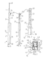
- a portable aerial cable lifting apparatus 1 comprising an elongate housing 2, a first telescopic member 3, a second telescopic member 4, a drive (not shown) operable at the housing 2, and a cable-engaging member 51 for lifting one or more aerial cables 53.
- the drive comprises a chain lever block 5 and a pulley arrangement 60.
- a first telescopic member 3 is extendable from and retractable into the housing 2
- a second telescopic member 4 is extendable from and retractable into the first telescopic member 3.
- the chain lever block 5 has a block 61, a chain 16 extending over the block 61, and a lever 12 for operating the block 61.
- the housing 2 is tubular, it has a ground-bearing base 10 and four sidewalls 11 (only some of which have been labelled) extending therefrom.
- the base 10 is wedge-shaped and the apparatus 1 can pivot relative to the ground about an edge of the wedge.
- Internal sidewalls 13, 18 and elongate nylon guides 17 ensure that the first telescopic member 3 extends and retracts correctly within the housing 2 (see Figure 3 ).
- Sidewalls 13 and 18 extend from the base 10 to a position below the block 61.
- the sidewalls 11, 13, 18 together provide two compartments 14, 15.
- the compartments 14, 15 collect and contain parts of the chain 16 hanging from opposite sides of the block 61, so as to prevent entanglement of the chain 16.
- a lifting flange 20 extends from a lower end of the first telescopic member 3 between sidewalls 13 and 18, and the chain 16 is attached to the flange 20.
- the block 5 is mounted to a sidewall 11 of the housing 2 for rotation relative thereto.
- Lever 12 extends from the sidewall 11.
- the first telescopic member 3 comprises a tube of rectangular cross-section and the second telescopic member 4 comprises a tube of circular cross-section.
- the housing 2 and telescopic members 3, 4 consist of aluminum or composite materials (eg. Kevlar ®) that will not buckle when placed under load.
- a pin 40 extends diametrically across an upper region of the second telescopic member 4, as seen in Figures 3 and 5 .
- a lifting flange 42 extends from a lower region of the second telescopic member 4, as seen in Figure 3 . Flange 42 prevents the second telescopic member 4 from rotating within the first telescopic member 3.
- the pulley arrangement 60 includes a main sheave 30, two additional smaller sheaves 31 and a wire cable 34.
- an angle bracket 33 mounts sheaves 30 and 31 to a front sidewall 32 of the first telescopic member 3.
- the front sidewall 32 has a pair of slits (not shown) through which extend sheaves 31.
- the cable 34 extends partly around each of the sheaves 30, 31 and through the slits.
- one end 35 of the cable 34 is attached to flange 42 and the other end 36 of the cable 34 is attached to the base 10 of the housing 2, so that when the first telescopic member 3 extends the second telescopic member 4 extends as well.
- FIGS 8 to 10 show different types of cable-engaging members 50, 51, 52 for lifting aerial cables 53.
- Each member 50, 51, 52 basically comprises a cylindrical body 57 and a headpiece 70 for engaging one or more cables 53.
- a lower end of the body 57 fits within the second telescopic member 4 and has a slot 54 that receives pin 40.
- the pin 40 prevents member 50 from rotating.
- the headpiece 70 of member 50 comprises a fork 55 for lifting a single cable 53.
- Member 52 differs from member 50 in that it has a second fork 56 of sorts (for a second cable 53) extending from the body 57.
- Member 51 differs from members 50 and 52 in that its headpiece 70 has an undulating surface 58. Each groove 59 of the undulating surface 58 can receive a cable 53. Undulating surface 58 enables multiple cables 53 to be lifted at any one time and to be kept in isolation from one another.
- the apparatus 1, with the telescopic members 3, 4 fully retracted, is positioned beneath one or more aerial cables (eg. overhead power lines) that need to be raised, so that, for instance, a truck carrying an oversized load may pass therebeneath.
- a suitable cable-engaging member 50, 51, 52 is attached to the second telescopic member 4.
- the chain lever block 5 is operated, the first telescopic member 3 extends from within the housing 2 and the second telescopic member 4 extends from the first telescopic member 3. If multiple cables need to be lifted, then either member 51 or 52 is used. If a single cable needs to be lifted, then any one of members 50 to 52 can be used.
- the telescopic members 3, 4 are extended until there is sufficient clearance between a top of the oversized load and the cable/s.
- the chain lever block 5 is locked such that the telescopic members 3, 4 cannot retract by accident.
- the apparatus 1 is insulated.
- the cable-engaging member 50, 51, 52 and/or the second telescopic member 4 can consist of a non-conductive material or can be insulated with rubber.
- the apparatus 1 is free standing and the apparatus 1 can, if necessary, pivot relative to the ground.
- the pivoting action enables the apparatus 1 to follow the movement of the lifted cable (such as when the cable sways when blown by wind) and reduces the bending moment on the apparatus 1.
- the apparatus can be used to raise one or more cables at any one time; since the apparatus is free standing whilst supporting the cable/s, other cables can be lifted by a single operator using additional like apparatuses; the apparatus can be used on uneven or sloping ground as it has a small ground-bearing surface; in the retracted state, the apparatus can be easily handled, transported and stored; an operator need not rely on physical strength to lift and hold a cable in the lifted position; since the apparatus is operable at ground level, an operator need not be in close proximity of an electrified cable; specialised machinery such as cherry pickers are not required; and, the apparatus can be positioned and extended in a time efficient manner with a great degree of accuracy and control.
Landscapes
- Life Sciences & Earth Sciences (AREA)
- Engineering & Computer Science (AREA)
- Geology (AREA)
- Mechanical Engineering (AREA)
- Structural Engineering (AREA)
- Forklifts And Lifting Vehicles (AREA)
- Load-Engaging Elements For Cranes (AREA)
- Electric Cable Installation (AREA)
- Bridges Or Land Bridges (AREA)
- Moulds For Moulding Plastics Or The Like (AREA)
Claims (16)
- Transportables Gerät (1) zum Anheben wenigstens eines Luftkabels, wobei das Gerät (1) folgendes umfasst: ein längliches Gehäuse (2); wenigstens ein erstes teleskopische Element (3), das aus dem länglichen Gehäuse (2) ausfahrbar und darin einfahrbar ist; einen Antrieb, der am länglichen Gehäuse (2) betreiben werden kann, um das erste teleskopische Element (3) auszufahren und einzufahren; und wenigstens ein Kabelgreifelement (50, 51, 52), das durch das erste teleskopische Element (3) positionierbar ist, um das wenigstens eine Luftkabel anzuheben, wenn das erste teleskopische Element (3) ausgefahren wurde, dadurch gekennzeichnet, dass eine Bodenlagerbasis (10) des Gehäuses (2) keilförmig und dazu geeignet ist, relativ zum Boden um eine Kante des Keils zu kippen, um der Bewegung des Luftkabels zu folgen, sollte das Luftkabel schaukeln, nachdem es angehoben wurde.
- Gerät (1) nach Anspruch 1, dadurch gekennzeichnet, dass der Antrieb einen Kettenhebelzug (5) umfasst, der am länglichen Gehäuse (2) montiert ist, und eine Kette (16) des Kettenhebelzugs (5) an einem unteren Ende des ersten teleskopischen Elements (3) angebracht ist.
- Gerät (1) nach Anspruch 2, dadurch gekennzeichnet, dass ein Block (61) des Kettenhebelzugs (5) innerhalb des länglichen Gehäuses (2) angeordnet ist, sich ein Bedienhebel (12) des Kettenhebelzugs (5) aus dem Inneren des länglichen Gehäuses (2) erstreckt und das längliche Gehäuse (2) separate Abteilungen (14, 15) zur Aufnahme von Teilen der Kette (16) aufweist, die sich von gegenüberliegenden Seiten des Blocks (61) erstrecken.
- Gerät (1) nach Anspruch 3, dadurch gekennzeichnet, dass das längliche Gehäuse (2) Innenführungen (17) für das erste teleskopische Element (3) aufweist.
- Gerät (1) nach einem der Ansprüche 2 bis 4, dadurch gekennzeichnet, dass das Gerät (1) darüber hinaus ein zweites teleskopisches Element (4) umfasst, das aus dem ersten teleskopischen Element (3) ausfahrbar und darin einfahrbar ist, und das Kabelgreifelement (50, 51, 52) am zweiten teleskopischen Element (4) angebracht ist.
- Gerät (1) nach Anspruch 5, dadurch gekennzeichnet, dass der Antrieb darüber hinaus eine Flaschenzuganordnung (60) zum Ausfahren und Einfahren des zweiten teleskopischen Elements (4) umfasst.
- Gerät (1) nach Anspruch 6, dadurch gekennzeichnet, dass die Flaschenzuganordnung (60) wenigstens eine Laufrolle (30) aufweist, die an einem oberen Ende des ersten teleskopischen Elements (3) angebracht ist, und ein flexibles Zugelement (34) der Flaschenzuganordnung (60) sich um die Laufrolle (30) erstreckt und jeweilige Enden aufweist, die an einem unteren Ende des zweiten teleskopischen Elements (4) und einem unteren Ende des länglichen Gehäuses (2) angebracht sind.
- Gerät (1) nach Anspruch 7, dadurch gekennzeichnet, dass wenn das erste teleskopische Element (3) mit dem Kettenhebelzug (5) hochgefahren wird, sich das zweite teleskopische Element (4) etwa doppelt so weit erstreckt, wie das erste teleskopische Element (3).
- Gerät (1) nach einem der Ansprüche 5 bis 8, dadurch gekennzeichnet, dass das Kabelgreifelement (50, 51, 52) einen Körper (57) besitzt, der austauschbar an einem oberen Ende des zweiten teleskopischen Elements (4) angebracht ist, und sich ein Kopfstück (70) vom Körper (57) erstreckt.
- Gerät (1) nach Anspruch 9, dadurch gekennzeichnet, dass das Kopfstück (70) und/oder der Körper (57) wenigstens eine Gabel oder Vertiefung (55, 56) aufweist, durch welche wenigstens eines der Kabel erfasst und angehoben werden kann.
- Gerät (1) nach Anspruch 10, dadurch gekennzeichnet, dass das Kopfstück (70) eine wellenförmige Oberfläche (58) aufweist und mehrere der Kabel innerhalb separater Furchen (59) der wellenförmigen Oberfläche (58) untergebracht werden können.
- Verfahren zum Anheben wenigstens eines Luftkabels, wobei das Verfahren die folgenden Schritte umfasst: a) Positionieren eines Hebegeräts (1) unter einem Luftkabel, wobei das Gerät (1) folgendes umfasst: ein Gehäuse (2); wenigstens ein erstes teleskopische Element (3), das aus dem Gehäuse (2) ausfahrbar und darin einfahrbar ist; einen Antrieb, der am Gehäuse (2) betreiben werden kann, um das erste teleskopische Element (3) auszufahren und einzufahren; wenigstens ein Kabelgreifelement (50, 51, 52), das durch das erste teleskopische Element (3) positionierbar ist, um das wenigstens eine Luftkabel anzuheben, wenn das erste teleskopische Element (3) ausgefahren wurde; und b) Anheben des Luftkabels, dadurch gekennzeichnet, dass eine Bodenlagerbasis (10) des Gehäuses (2) keilförmig und dazu geeignet ist, relativ zum Boden um eine Kante des Keils zu kippen, um der Bewegung des Luftkabels zu folgen, sollte das Luftkabel schaukeln, nachdem es angehoben wurde.
- Verfahren nach Anspruch 12, dadurch gekennzeichnet, dass das Gerät (1) nur dann freisteht, während es das Luftkabel abstützt.
- Verfahren nach Anspruch 12 oder Anspruch 13, dadurch gekennzeichnet, dass das Gerät (1) darüber hinaus ein zweites teleskopisches Element (4) umfasst, das aus dem ersten teleskopischen Element (3) ausfahrbar und darin einfahrbar ist, und das Kabelgreifelement (50, 51, 52) am zweiten teleskopischen Element (4) angebracht ist.
- Verfahren nach einem der Ansprüche 12 bis 14, dadurch gekennzeichnet, dass das Kabelgreifelement (51) gleichzeitig mehrere Luftkabel isoliert voneinander anhebt.
- Verfahren nach einem der Ansprüche 12 bis 14, dadurch gekennzeichnet, dass das Gehäuse (2) röhrenförmig ist.
Applications Claiming Priority (3)
| Application Number | Priority Date | Filing Date | Title |
|---|---|---|---|
| AUPS084202 | 2002-03-01 | ||
| AUPS0842A AUPS084202A0 (en) | 2002-03-01 | 2002-03-01 | A lifting apparatus |
| PCT/AU2003/000256 WO2003074415A1 (en) | 2002-03-01 | 2003-03-03 | Apparatus and method for lifting aerial cables |
Publications (3)
| Publication Number | Publication Date |
|---|---|
| EP1487733A1 EP1487733A1 (de) | 2004-12-22 |
| EP1487733A4 EP1487733A4 (de) | 2005-05-25 |
| EP1487733B1 true EP1487733B1 (de) | 2009-08-12 |
Family
ID=3834441
Family Applications (1)
| Application Number | Title | Priority Date | Filing Date |
|---|---|---|---|
| EP03702219A Expired - Lifetime EP1487733B1 (de) | 2002-03-01 | 2003-03-03 | Vorrichtung und verfahren zum anheben von luftkabeln |
Country Status (15)
| Country | Link |
|---|---|
| US (1) | US7156354B2 (de) |
| EP (1) | EP1487733B1 (de) |
| JP (1) | JP4129512B2 (de) |
| KR (1) | KR100970033B1 (de) |
| AT (1) | ATE439329T1 (de) |
| AU (2) | AUPS084202A0 (de) |
| BR (1) | BRPI0308177B1 (de) |
| CA (1) | CA2477123C (de) |
| DE (1) | DE60328760D1 (de) |
| DK (1) | DK1487733T3 (de) |
| ES (1) | ES2331566T3 (de) |
| NZ (1) | NZ535352A (de) |
| PT (1) | PT1487733E (de) |
| WO (1) | WO2003074415A1 (de) |
| ZA (1) | ZA200407735B (de) |
Cited By (1)
| Publication number | Priority date | Publication date | Assignee | Title |
|---|---|---|---|---|
| CN104124642A (zh) * | 2014-06-13 | 2014-10-29 | 江苏省电力公司江阴市供电公司 | 多功能智能绝缘提线器 |
Families Citing this family (14)
| Publication number | Priority date | Publication date | Assignee | Title |
|---|---|---|---|---|
| WO2007011398A2 (en) | 2004-10-21 | 2007-01-25 | Deka Products Limited Partnership | Controllable launcher |
| CN101472432B (zh) * | 2007-12-27 | 2011-11-30 | 鸿富锦精密工业(深圳)有限公司 | 调整机构 |
| CN101481073B (zh) * | 2008-01-09 | 2012-03-14 | 鸿富锦精密工业(深圳)有限公司 | 升降机构及其气缸 |
| AU2009202541B2 (en) * | 2008-06-24 | 2014-05-22 | Ostaric, Mariella | Safety Lead Stand |
| US7896298B2 (en) * | 2008-07-11 | 2011-03-01 | Amg Medical Inc. | Intravenous support apparatus |
| CA2667691A1 (en) * | 2008-07-14 | 2010-01-14 | Harvey Roth | Fluid bag stand |
| US7834487B2 (en) * | 2008-09-08 | 2010-11-16 | Netz Dana A | Shorting stick for safing of high-voltage equipment |
| US8278863B2 (en) * | 2009-06-16 | 2012-10-02 | Ns Microwave | Telescoping mast |
| US9768576B2 (en) | 2014-03-20 | 2017-09-19 | Dominion Energy, Inc. | Shotgun stick with remote controller |
| CN109713612B (zh) * | 2018-12-24 | 2024-04-12 | 国家电网有限公司 | 迪尼玛绳高空收紧装置 |
| JP6820573B2 (ja) * | 2019-01-15 | 2021-01-27 | 東日本電信電話株式会社 | 竿状構造体 |
| CN114803931B (zh) * | 2021-01-22 | 2023-12-05 | 国网智能科技股份有限公司 | 配网带电作业机器人导线举升装置、方法及机器人 |
| CN114852903B (zh) * | 2022-05-24 | 2023-09-12 | 柳州欧维姆机械股份有限公司 | 一种千斤顶与收放线装置协同作业控制方法及系统 |
| CN120834436B (zh) * | 2025-09-17 | 2026-01-20 | 国网瑞嘉(天津)智能机器人有限公司 | 一种用于机器人的带电搭接电缆装置及控制方法 |
Family Cites Families (12)
| Publication number | Priority date | Publication date | Assignee | Title |
|---|---|---|---|---|
| US1384761A (en) | 1920-04-14 | 1921-07-19 | James H Jessup | Cable-tie hanger |
| US1581325A (en) * | 1925-02-04 | 1926-04-20 | Russell J Sands | Extensible mast and supporting means therefor |
| US1725329A (en) * | 1927-08-19 | 1929-08-20 | Alsace S Blandford | Wall-board-handling device |
| US1748597A (en) * | 1928-03-29 | 1930-02-25 | James H Collins | Clothes tree |
| US2391536A (en) * | 1944-07-21 | 1945-12-25 | Edward M Anderson | Clothes post |
| US3788691A (en) | 1972-04-17 | 1974-01-29 | Hastings Fiber Glass Prod Inc | Shotgun stick |
| DE2620458A1 (de) | 1976-05-08 | 1977-11-24 | Werner Chudzik | Vorrichtung zum heranbringen von rettungsgeraeten an die gefahrenstelle, insbesondere fuer mehrgeschossige haeuser und zum einsatz bei feuerwehren |
| US4079978A (en) | 1976-12-03 | 1978-03-21 | Hastings Fiber Glass Products, Inc. | Hot stick with air cushion |
| DE2854034A1 (de) | 1978-12-14 | 1980-07-03 | Porsche Ag | Hubvorrichtung, insbesondere fuer brandbekaempfungs- und/oder rettungsfahrzeuge |
| CA2036617C (en) | 1990-02-20 | 1996-04-23 | Mitsuhiro Kishi | Lifting apparatus |
| DE4031105C2 (de) | 1990-10-02 | 2000-03-09 | High Tech Geraetebau | Teleskopartig ausfahrbare Hubsäule, insbesondere zur Höhenverstellung einer Kamera |
| US5533593A (en) | 1994-10-12 | 1996-07-09 | Huang; Andy C.-P. | Mobile lifter |
-
2002
- 2002-03-01 AU AUPS0842A patent/AUPS084202A0/en not_active Abandoned
-
2003
- 2003-03-03 KR KR1020047013578A patent/KR100970033B1/ko not_active Expired - Fee Related
- 2003-03-03 ES ES03702219T patent/ES2331566T3/es not_active Expired - Lifetime
- 2003-03-03 DK DK03702219T patent/DK1487733T3/da active
- 2003-03-03 EP EP03702219A patent/EP1487733B1/de not_active Expired - Lifetime
- 2003-03-03 US US10/504,858 patent/US7156354B2/en not_active Expired - Lifetime
- 2003-03-03 AU AU2003205449A patent/AU2003205449B2/en not_active Ceased
- 2003-03-03 PT PT03702219T patent/PT1487733E/pt unknown
- 2003-03-03 AT AT03702219T patent/ATE439329T1/de active
- 2003-03-03 CA CA2477123A patent/CA2477123C/en not_active Expired - Fee Related
- 2003-03-03 WO PCT/AU2003/000256 patent/WO2003074415A1/en not_active Ceased
- 2003-03-03 BR BRPI0308177-0A patent/BRPI0308177B1/pt not_active IP Right Cessation
- 2003-03-03 JP JP2003572895A patent/JP4129512B2/ja not_active Expired - Fee Related
- 2003-03-03 DE DE60328760T patent/DE60328760D1/de not_active Expired - Lifetime
- 2003-03-03 NZ NZ535352A patent/NZ535352A/en not_active IP Right Cessation
-
2004
- 2004-09-23 ZA ZA2004/07735A patent/ZA200407735B/en unknown
Cited By (1)
| Publication number | Priority date | Publication date | Assignee | Title |
|---|---|---|---|---|
| CN104124642A (zh) * | 2014-06-13 | 2014-10-29 | 江苏省电力公司江阴市供电公司 | 多功能智能绝缘提线器 |
Also Published As
| Publication number | Publication date |
|---|---|
| PT1487733E (pt) | 2009-11-11 |
| AU2003205449B2 (en) | 2007-06-14 |
| EP1487733A1 (de) | 2004-12-22 |
| DE60328760D1 (de) | 2009-09-24 |
| ES2331566T3 (es) | 2010-01-08 |
| JP2005519570A (ja) | 2005-06-30 |
| AUPS084202A0 (en) | 2002-03-21 |
| BR0308177A (pt) | 2005-01-11 |
| ATE439329T1 (de) | 2009-08-15 |
| CA2477123C (en) | 2011-07-19 |
| BRPI0308177B1 (pt) | 2015-03-24 |
| DK1487733T3 (da) | 2009-12-14 |
| JP4129512B2 (ja) | 2008-08-06 |
| KR100970033B1 (ko) | 2010-07-16 |
| WO2003074415A1 (en) | 2003-09-12 |
| EP1487733A4 (de) | 2005-05-25 |
| ZA200407735B (en) | 2005-12-28 |
| CA2477123A1 (en) | 2003-09-12 |
| US20050156092A1 (en) | 2005-07-21 |
| KR20040095245A (ko) | 2004-11-12 |
| AU2003205449A1 (en) | 2003-09-16 |
| NZ535352A (en) | 2006-01-27 |
| US7156354B2 (en) | 2007-01-02 |
Similar Documents
| Publication | Publication Date | Title |
|---|---|---|
| EP1487733B1 (de) | Vorrichtung und verfahren zum anheben von luftkabeln | |
| US5035336A (en) | Compact collapsible manhole cover lifter | |
| US4466506A (en) | Wire lift device for high tension electric line | |
| US8684335B2 (en) | Portable hoist for hand trucks | |
| US6945742B2 (en) | Portable manhole cover remover | |
| US10622791B2 (en) | Field-mountable winch assembly | |
| US4596336A (en) | Mobile crane | |
| US4721213A (en) | Equipment and method for installing apparatus at elevated locations | |
| US4310098A (en) | Portable boom structure | |
| US10662046B1 (en) | Boom-mountable material handler | |
| US4582206A (en) | Mobile aerial hoist | |
| US20040040925A1 (en) | Portable lift apparatus | |
| US6616397B1 (en) | Hoist system and method of use | |
| US6648570B2 (en) | Lifting and installing streetlight poles | |
| US20050189527A1 (en) | Aerial cable placing machine | |
| CN216764125U (zh) | 一种建筑工地用地面吊装移动工具 | |
| EP1405817A1 (de) | Teleskopischer,zerlegbarer und herausziehbarer Kran zum Installieren auf einem Transportmittel zum Laden und Entladen von Material | |
| US4364545A (en) | Well servicing apparatus | |
| CN215160610U (zh) | 一种可进行多方位固定防滑动的升降平台 | |
| CN212766328U (zh) | 一种电缆运输用乌龟车 | |
| US12158136B2 (en) | Rope driver, portable device for driving a rope comprising a rope driver, kit, method and use | |
| CN210285567U (zh) | 一种用于电梯维修的多功能搬运杆 | |
| EP0159543B1 (de) | Arbeitsplattformbefestigung für hydraulischen Kran | |
| AU2005203153A1 (en) | Safety system for truck loading or unloading | |
| JP2981615B1 (ja) | 電柱支持補助用自在台車 |
Legal Events
| Date | Code | Title | Description |
|---|---|---|---|
| PUAI | Public reference made under article 153(3) epc to a published international application that has entered the european phase |
Free format text: ORIGINAL CODE: 0009012 |
|
| 17P | Request for examination filed |
Effective date: 20040916 |
|
| AK | Designated contracting states |
Kind code of ref document: A1 Designated state(s): AT BE BG CH CY CZ DE DK EE ES FI FR GB GR HU IE IT LI LU MC NL PT RO SE SI SK TR |
|
| AX | Request for extension of the european patent |
Extension state: AL LT LV MK RO |
|
| RAP1 | Party data changed (applicant data changed or rights of an application transferred) |
Owner name: MSCLE HOLDINGS PTY LTD |
|
| RIN1 | Information on inventor provided before grant (corrected) |
Inventor name: SHEPHERD, KEIRON Inventor name: CLEM, TREVOR JOHN |
|
| A4 | Supplementary search report drawn up and despatched |
Effective date: 20050408 |
|
| RIC1 | Information provided on ipc code assigned before grant |
Ipc: 7B 66F 11/00 A Ipc: 7H 02G 7/00 B Ipc: 7B 25J 1/04 B Ipc: 7H 02G 1/02 B |
|
| 17Q | First examination report despatched |
Effective date: 20071213 |
|
| GRAP | Despatch of communication of intention to grant a patent |
Free format text: ORIGINAL CODE: EPIDOSNIGR1 |
|
| GRAS | Grant fee paid |
Free format text: ORIGINAL CODE: EPIDOSNIGR3 |
|
| GRAA | (expected) grant |
Free format text: ORIGINAL CODE: 0009210 |
|
| AK | Designated contracting states |
Kind code of ref document: B1 Designated state(s): AT BE BG CH CY CZ DE DK EE ES FI FR GB GR HU IE IT LI LU MC NL PT RO SE SI SK TR |
|
| REG | Reference to a national code |
Ref country code: GB Ref legal event code: FG4D |
|
| REG | Reference to a national code |
Ref country code: CH Ref legal event code: EP |
|
| REG | Reference to a national code |
Ref country code: IE Ref legal event code: FG4D |
|
| REF | Corresponds to: |
Ref document number: 60328760 Country of ref document: DE Date of ref document: 20090924 Kind code of ref document: P |
|
| REG | Reference to a national code |
Ref country code: PT Ref legal event code: SC4A Free format text: AVAILABILITY OF NATIONAL TRANSLATION Effective date: 20091103 |
|
| REG | Reference to a national code |
Ref country code: CH Ref legal event code: NV Representative=s name: RIEDERER HASLER & PARTNER PATENTANWAELTE AG |
|
| REG | Reference to a national code |
Ref country code: SE Ref legal event code: TRGR |
|
| REG | Reference to a national code |
Ref country code: DK Ref legal event code: T3 |
|
| REG | Reference to a national code |
Ref country code: GR Ref legal event code: EP Ref document number: 20090402728 Country of ref document: GR |
|
| REG | Reference to a national code |
Ref country code: ES Ref legal event code: FG2A Ref document number: 2331566 Country of ref document: ES Kind code of ref document: T3 |
|
| PG25 | Lapsed in a contracting state [announced via postgrant information from national office to epo] |
Ref country code: SI Free format text: LAPSE BECAUSE OF FAILURE TO SUBMIT A TRANSLATION OF THE DESCRIPTION OR TO PAY THE FEE WITHIN THE PRESCRIBED TIME-LIMIT Effective date: 20090812 |
|
| REG | Reference to a national code |
Ref country code: HU Ref legal event code: AG4A Ref document number: E006775 Country of ref document: HU |
|
| PG25 | Lapsed in a contracting state [announced via postgrant information from national office to epo] |
Ref country code: BG Free format text: LAPSE BECAUSE OF FAILURE TO SUBMIT A TRANSLATION OF THE DESCRIPTION OR TO PAY THE FEE WITHIN THE PRESCRIBED TIME-LIMIT Effective date: 20091112 |
|
| PG25 | Lapsed in a contracting state [announced via postgrant information from national office to epo] |
Ref country code: RO Free format text: LAPSE BECAUSE OF FAILURE TO SUBMIT A TRANSLATION OF THE DESCRIPTION OR TO PAY THE FEE WITHIN THE PRESCRIBED TIME-LIMIT Effective date: 20090812 Ref country code: EE Free format text: LAPSE BECAUSE OF FAILURE TO SUBMIT A TRANSLATION OF THE DESCRIPTION OR TO PAY THE FEE WITHIN THE PRESCRIBED TIME-LIMIT Effective date: 20090812 |
|
| PG25 | Lapsed in a contracting state [announced via postgrant information from national office to epo] |
Ref country code: SK Free format text: LAPSE BECAUSE OF FAILURE TO SUBMIT A TRANSLATION OF THE DESCRIPTION OR TO PAY THE FEE WITHIN THE PRESCRIBED TIME-LIMIT Effective date: 20090812 |
|
| PLBE | No opposition filed within time limit |
Free format text: ORIGINAL CODE: 0009261 |
|
| STAA | Information on the status of an ep patent application or granted ep patent |
Free format text: STATUS: NO OPPOSITION FILED WITHIN TIME LIMIT |
|
| 26N | No opposition filed |
Effective date: 20100517 |
|
| PG25 | Lapsed in a contracting state [announced via postgrant information from national office to epo] |
Ref country code: MC Free format text: LAPSE BECAUSE OF NON-PAYMENT OF DUE FEES Effective date: 20100331 |
|
| PG25 | Lapsed in a contracting state [announced via postgrant information from national office to epo] |
Ref country code: CY Free format text: LAPSE BECAUSE OF FAILURE TO SUBMIT A TRANSLATION OF THE DESCRIPTION OR TO PAY THE FEE WITHIN THE PRESCRIBED TIME-LIMIT Effective date: 20090812 |
|
| PG25 | Lapsed in a contracting state [announced via postgrant information from national office to epo] |
Ref country code: LU Free format text: LAPSE BECAUSE OF NON-PAYMENT OF DUE FEES Effective date: 20100303 |
|
| PG25 | Lapsed in a contracting state [announced via postgrant information from national office to epo] |
Ref country code: TR Free format text: LAPSE BECAUSE OF FAILURE TO SUBMIT A TRANSLATION OF THE DESCRIPTION OR TO PAY THE FEE WITHIN THE PRESCRIBED TIME-LIMIT Effective date: 20090812 |
|
| REG | Reference to a national code |
Ref country code: FR Ref legal event code: PLFP Year of fee payment: 14 |
|
| REG | Reference to a national code |
Ref country code: FR Ref legal event code: PLFP Year of fee payment: 15 |
|
| PGFP | Annual fee paid to national office [announced via postgrant information from national office to epo] |
Ref country code: NL Payment date: 20170315 Year of fee payment: 15 Ref country code: GR Payment date: 20170327 Year of fee payment: 15 Ref country code: CH Payment date: 20170320 Year of fee payment: 15 |
|
| PGFP | Annual fee paid to national office [announced via postgrant information from national office to epo] |
Ref country code: IE Payment date: 20170320 Year of fee payment: 15 Ref country code: AT Payment date: 20170327 Year of fee payment: 15 Ref country code: DK Payment date: 20170323 Year of fee payment: 15 Ref country code: PT Payment date: 20170302 Year of fee payment: 15 Ref country code: HU Payment date: 20170302 Year of fee payment: 15 Ref country code: BE Payment date: 20170315 Year of fee payment: 15 |
|
| PGFP | Annual fee paid to national office [announced via postgrant information from national office to epo] |
Ref country code: IT Payment date: 20170321 Year of fee payment: 15 |
|
| PGFP | Annual fee paid to national office [announced via postgrant information from national office to epo] |
Ref country code: ES Payment date: 20170328 Year of fee payment: 15 |
|
| REG | Reference to a national code |
Ref country code: FR Ref legal event code: PLFP Year of fee payment: 16 |
|
| REG | Reference to a national code |
Ref country code: DK Ref legal event code: EBP Effective date: 20180331 |
|
| PG25 | Lapsed in a contracting state [announced via postgrant information from national office to epo] |
Ref country code: PT Free format text: LAPSE BECAUSE OF NON-PAYMENT OF DUE FEES Effective date: 20180903 |
|
| REG | Reference to a national code |
Ref country code: CH Ref legal event code: PL |
|
| REG | Reference to a national code |
Ref country code: NL Ref legal event code: MM Effective date: 20180401 |
|
| REG | Reference to a national code |
Ref country code: AT Ref legal event code: MM01 Ref document number: 439329 Country of ref document: AT Kind code of ref document: T Effective date: 20180303 |
|
| REG | Reference to a national code |
Ref country code: BE Ref legal event code: MM Effective date: 20180331 |
|
| REG | Reference to a national code |
Ref country code: IE Ref legal event code: MM4A |
|
| PG25 | Lapsed in a contracting state [announced via postgrant information from national office to epo] |
Ref country code: NL Free format text: LAPSE BECAUSE OF NON-PAYMENT OF DUE FEES Effective date: 20180401 |
|
| PG25 | Lapsed in a contracting state [announced via postgrant information from national office to epo] |
Ref country code: HU Free format text: LAPSE BECAUSE OF NON-PAYMENT OF DUE FEES Effective date: 20180304 Ref country code: GR Free format text: LAPSE BECAUSE OF NON-PAYMENT OF DUE FEES Effective date: 20181003 Ref country code: IE Free format text: LAPSE BECAUSE OF NON-PAYMENT OF DUE FEES Effective date: 20180303 Ref country code: AT Free format text: LAPSE BECAUSE OF NON-PAYMENT OF DUE FEES Effective date: 20180303 |
|
| PG25 | Lapsed in a contracting state [announced via postgrant information from national office to epo] |
Ref country code: BE Free format text: LAPSE BECAUSE OF NON-PAYMENT OF DUE FEES Effective date: 20180331 Ref country code: CH Free format text: LAPSE BECAUSE OF NON-PAYMENT OF DUE FEES Effective date: 20180331 Ref country code: LI Free format text: LAPSE BECAUSE OF NON-PAYMENT OF DUE FEES Effective date: 20180331 Ref country code: IT Free format text: LAPSE BECAUSE OF NON-PAYMENT OF DUE FEES Effective date: 20180303 |
|
| PG25 | Lapsed in a contracting state [announced via postgrant information from national office to epo] |
Ref country code: DK Free format text: LAPSE BECAUSE OF NON-PAYMENT OF DUE FEES Effective date: 20180331 |
|
| REG | Reference to a national code |
Ref country code: ES Ref legal event code: FD2A Effective date: 20190904 |
|
| PG25 | Lapsed in a contracting state [announced via postgrant information from national office to epo] |
Ref country code: ES Free format text: LAPSE BECAUSE OF NON-PAYMENT OF DUE FEES Effective date: 20180304 |
|
| PGFP | Annual fee paid to national office [announced via postgrant information from national office to epo] |
Ref country code: FI Payment date: 20200309 Year of fee payment: 18 Ref country code: SE Payment date: 20200310 Year of fee payment: 18 Ref country code: DE Payment date: 20200218 Year of fee payment: 18 Ref country code: GB Payment date: 20200219 Year of fee payment: 18 |
|
| PGFP | Annual fee paid to national office [announced via postgrant information from national office to epo] |
Ref country code: CZ Payment date: 20200218 Year of fee payment: 18 |
|
| PGFP | Annual fee paid to national office [announced via postgrant information from national office to epo] |
Ref country code: FR Payment date: 20200214 Year of fee payment: 18 |
|
| REG | Reference to a national code |
Ref country code: DE Ref legal event code: R119 Ref document number: 60328760 Country of ref document: DE |
|
| REG | Reference to a national code |
Ref country code: FI Ref legal event code: MAE |
|
| PG25 | Lapsed in a contracting state [announced via postgrant information from national office to epo] |
Ref country code: CZ Free format text: LAPSE BECAUSE OF NON-PAYMENT OF DUE FEES Effective date: 20210303 Ref country code: FI Free format text: LAPSE BECAUSE OF NON-PAYMENT OF DUE FEES Effective date: 20210303 |
|
| GBPC | Gb: european patent ceased through non-payment of renewal fee |
Effective date: 20210303 |
|
| PG25 | Lapsed in a contracting state [announced via postgrant information from national office to epo] |
Ref country code: SE Free format text: LAPSE BECAUSE OF NON-PAYMENT OF DUE FEES Effective date: 20210304 Ref country code: DE Free format text: LAPSE BECAUSE OF NON-PAYMENT OF DUE FEES Effective date: 20211001 Ref country code: FR Free format text: LAPSE BECAUSE OF NON-PAYMENT OF DUE FEES Effective date: 20210331 Ref country code: GB Free format text: LAPSE BECAUSE OF NON-PAYMENT OF DUE FEES Effective date: 20210303 |