EP1487723B1 - Rodless conveyor belt or chain - Google Patents
Rodless conveyor belt or chain Download PDFInfo
- Publication number
- EP1487723B1 EP1487723B1 EP03711243A EP03711243A EP1487723B1 EP 1487723 B1 EP1487723 B1 EP 1487723B1 EP 03711243 A EP03711243 A EP 03711243A EP 03711243 A EP03711243 A EP 03711243A EP 1487723 B1 EP1487723 B1 EP 1487723B1
- Authority
- EP
- European Patent Office
- Prior art keywords
- link
- link section
- section
- adjacent
- belt
- Prior art date
- Legal status (The legal status is an assumption and is not a legal conclusion. Google has not performed a legal analysis and makes no representation as to the accuracy of the status listed.)
- Expired - Lifetime
Links
- 230000008878 coupling Effects 0.000 claims description 15
- 238000010168 coupling process Methods 0.000 claims description 15
- 238000005859 coupling reaction Methods 0.000 claims description 15
- 239000000463 material Substances 0.000 description 17
- 239000004033 plastic Substances 0.000 description 9
- 229920003023 plastic Polymers 0.000 description 9
- 241001270131 Agaricus moelleri Species 0.000 description 7
- 238000012546 transfer Methods 0.000 description 6
- 230000009471 action Effects 0.000 description 5
- 238000004519 manufacturing process Methods 0.000 description 5
- 238000013461 design Methods 0.000 description 4
- 239000004744 fabric Substances 0.000 description 4
- 238000000034 method Methods 0.000 description 4
- 238000012986 modification Methods 0.000 description 4
- 230000004048 modification Effects 0.000 description 4
- 230000008901 benefit Effects 0.000 description 3
- 229910001220 stainless steel Inorganic materials 0.000 description 3
- 239000010935 stainless steel Substances 0.000 description 3
- 239000004743 Polypropylene Substances 0.000 description 2
- DHKHKXVYLBGOIT-UHFFFAOYSA-N acetaldehyde Diethyl Acetal Natural products CCOC(C)OCC DHKHKXVYLBGOIT-UHFFFAOYSA-N 0.000 description 2
- 125000002777 acetyl group Chemical class [H]C([H])([H])C(*)=O 0.000 description 2
- 239000000853 adhesive Substances 0.000 description 2
- 230000001070 adhesive effect Effects 0.000 description 2
- 238000013459 approach Methods 0.000 description 2
- 238000013037 co-molding Methods 0.000 description 2
- 239000002131 composite material Substances 0.000 description 2
- 230000001010 compromised effect Effects 0.000 description 2
- 238000010276 construction Methods 0.000 description 2
- 230000008030 elimination Effects 0.000 description 2
- 238000003379 elimination reaction Methods 0.000 description 2
- 238000005192 partition Methods 0.000 description 2
- -1 polypropylene Polymers 0.000 description 2
- 229920001155 polypropylene Polymers 0.000 description 2
- 229920000785 ultra high molecular weight polyethylene Polymers 0.000 description 2
- 235000015173 baked goods and baking mixes Nutrition 0.000 description 1
- 239000011324 bead Substances 0.000 description 1
- 230000009286 beneficial effect Effects 0.000 description 1
- 230000002457 bidirectional effect Effects 0.000 description 1
- 230000008859 change Effects 0.000 description 1
- 230000003247 decreasing effect Effects 0.000 description 1
- 230000002939 deleterious effect Effects 0.000 description 1
- 238000012938 design process Methods 0.000 description 1
- 238000011161 development Methods 0.000 description 1
- 235000013305 food Nutrition 0.000 description 1
- 238000002844 melting Methods 0.000 description 1
- 230000008018 melting Effects 0.000 description 1
- 239000002184 metal Substances 0.000 description 1
- 238000000465 moulding Methods 0.000 description 1
- 239000002245 particle Substances 0.000 description 1
- 230000008569 process Effects 0.000 description 1
- 230000008439 repair process Effects 0.000 description 1
- 230000007704 transition Effects 0.000 description 1
- 238000011144 upstream manufacturing Methods 0.000 description 1
- 239000011800 void material Substances 0.000 description 1
- 230000003313 weakening effect Effects 0.000 description 1
- 238000003466 welding Methods 0.000 description 1
Images


Classifications
-
- B—PERFORMING OPERATIONS; TRANSPORTING
- B65—CONVEYING; PACKING; STORING; HANDLING THIN OR FILAMENTARY MATERIAL
- B65G—TRANSPORT OR STORAGE DEVICES, e.g. CONVEYORS FOR LOADING OR TIPPING, SHOP CONVEYOR SYSTEMS OR PNEUMATIC TUBE CONVEYORS
- B65G17/00—Conveyors having an endless traction element, e.g. a chain, transmitting movement to a continuous or substantially-continuous load-carrying surface or to a series of individual load-carriers; Endless-chain conveyors in which the chains form the load-carrying surface
- B65G17/30—Details; Auxiliary devices
- B65G17/38—Chains or like traction elements; Connections between traction elements and load-carriers
- B65G17/40—Chains acting as load-carriers
-
- B—PERFORMING OPERATIONS; TRANSPORTING
- B65—CONVEYING; PACKING; STORING; HANDLING THIN OR FILAMENTARY MATERIAL
- B65G—TRANSPORT OR STORAGE DEVICES, e.g. CONVEYORS FOR LOADING OR TIPPING, SHOP CONVEYOR SYSTEMS OR PNEUMATIC TUBE CONVEYORS
- B65G17/00—Conveyors having an endless traction element, e.g. a chain, transmitting movement to a continuous or substantially-continuous load-carrying surface or to a series of individual load-carriers; Endless-chain conveyors in which the chains form the load-carrying surface
- B65G17/06—Conveyors having an endless traction element, e.g. a chain, transmitting movement to a continuous or substantially-continuous load-carrying surface or to a series of individual load-carriers; Endless-chain conveyors in which the chains form the load-carrying surface having a load-carrying surface formed by a series of interconnected, e.g. longitudinal, links, plates, or platforms
- B65G17/08—Conveyors having an endless traction element, e.g. a chain, transmitting movement to a continuous or substantially-continuous load-carrying surface or to a series of individual load-carriers; Endless-chain conveyors in which the chains form the load-carrying surface having a load-carrying surface formed by a series of interconnected, e.g. longitudinal, links, plates, or platforms the surface being formed by the traction element
Definitions
- the present invention relates to the conveyor art and, more particularly, to a modular link or link section for forming a "rodless" conveyor belt or chain, including a portion or section thereof.
- modular conveyor systems are extensively utilized to transport articles to and from various work stations during all stages of production.
- manufacturers using production lines with conveyors as an integral component of the material handling system have realized reasonably significant gains in productivity and resource utilization.
- modular conveyor systems have become even more widely implemented and have been adapted to meet an even wider scope of the material handling needs of producers of a multitude of consumer and industrial goods. Therefore, the continual development of improved modular conveyors is necessary in order to keep pace with the demands and expectations of the users of such conveyors.
- the belts or chains used in such conveyors are formed of a plurality of laterally repeating modular links, or unitary link sections comprising a plurality of laterally repeating link-shaped structures (collectively referred to as "links").
- the links are typically formed of a low-cost, high strength, wear resistant material, such as Acetal or UHMW polypropylene).
- a plurality of links or link sections are positioned in interdigitating, longitudinally repeating rows. Each row is then connected to the adjacent row by a transverse connecting rod that projects through one or more apertures in a first, usually leading portion of a first link or link section and one or more apertures or slots in a second, or trailing portion of the next-adjacent link or link section.
- a slot is provided for receiving a locking structure, such as a tab, that holds the transverse connector rod in place.
- a locking structure such as a tab
- the belt disclosed in the '296 patent is ostensibly capable of behaving more like a continuous piece of material than a conventional modular link conveyor belt
- the primary disadvantage is the need for an extraordinary number of man hours to form the belt.
- the assembler must position two link sections adjacent to each other, align them in an interdigitated relationship, and then thread the narrow plastic rod through the aligned apertures. Since there are no locking tabs or the like, both ends of the connector rod must then be mutilated to ensure that it remains held in place.
- the mutilated end may also inhibit one link section from freely pivoting relative to the next-adjacent link section.
- the links disclosed in the '901 patent are not readily adaptable for being scaled down to create a "micropitch" belt or chain, since each includes many intricate features that would be exceptionally difficult to replicate in a substantially smaller version (e.g., a link that is less than about 6 millimeters in height).
- a substantially smaller version e.g., a link that is less than about 6 millimeters in height.
- the strength of structures such as the opposed integral stub shafts projecting from each link may be compromised if made substantially smaller.
- the height-to-pitch ratio of the belt depicted in that patent is also low (e.g., 5 millimeters/27 millimeters, or around 0.25), which means that it is not well-suited for traversing over structures having a small radius of curvature, such as the rounded end of a bed in a transfer conveyor, a nose bar, or like structure.
- GB 2282115 discloses modular link sections, which can be coupled together to form a conveyor belt.
- the modular link sections are interconnected by coupling a bar located on one link section to a hook or another link section.
- Forming the belt or chain from a plurality of links or link sections to create a relatively wide conveying surface, and possibly one with a completely flat top portion, would facilitate receiving and transporting many different types of articles, including possibly as part of a transfer assembly positioned between the ends of two adjacent conveyors.
- Driving the belt or chain could also be accomplished using a sprocket or a friction drive, which would enhance the versatility and concomitantly increase the options available to the conveyor system designer.
- the elimination of the connector rods would also greatly facilitate forming a "micropitch" belt or chain using such links or link sections, which could be used in regular conveyors, transfer conveyors, or the like.
- a "rodless" belt or chain having these capabilities would fulfill a long-felt need by solving the various problems and addressing the limitations of prior art belts or chains identified in the foregoing discussion.
- a modular link section for intended use in coupling with an adjacent link or link section to form a part of a conveyor belt for conveying articles or products.
- the link section comprises a unitary body including a plurality of laterally repeating link-shaped portions.
- Each link-shaped portion includes a surface capable of engaging or assisting in supporting the particles or products being conveyed, a pair of leg portions, at least one first integral connector extending between the leg portions, and a receiver capable of receiving a portion of the adjacent link in snap-fit engagement.
- the snap-fit engagement allows for the easy and secure assembly of the link or link section with the adjacent one to form the part of the conveyor belt.
- each link-shaped portion also include an outer sidewall, and a second integral connector is provided between the outer sidewall of one leg portion of a first link-shaped portion and the adjacent outer sidewall of one leg portion of a second, adjacent link-shaped portion.
- the second integral connector is adapted for engaging a tooth on a drive or idler sprocket for driving or guiding the belt.
- the receiver includes an oversized entryway and opposed, inwardly sloping or tapered sidewalls that form a neck.
- the portion of the adjacent link section passes through the oversized entryway, along the inwardly sloping sidewalls, and snaps past the neck to become captured in the receiver, thereby creating the desired snap-fit engagement.
- a unitary modular link for intended use in coupling with an adjacent link to form a part or section of a conveyor belt for conveying articles or products.
- the link comprises a plurality of laterally repeating apex portions, each including a surface capable of engaging or assisting in supporting the articles or products being conveyed.
- a pair of leg portions extend from each apex portion, and at least one integral connector is positioned between the leg portions.
- Each apex portion includes a receiver capable of receiving a portion of the adjacent link in snap-fit engagement. This allows for the easy and secure assembly of the link with the adjacent link to form the part or section of the conveyor belt.
- the receiver in each apex portion includes an oversized entryway and opposed, inwardly sloping or tapered sidewalls that form a neck. Accordingly, the portion of the adjacent link passes through the oversized entryway, along the sloping sidewalls, and snaps past the neck to become captured in the receiver and create the desired snap-fit engagement.
- the leg portions of each apex portion may further include an outer sidewall.
- a second integral connector is provided between the outer sidewall of one leg portion of a first apex portion and the adjacent outer sidewall of one leg portion of a second, adjacent apex portion. The second integral connector is adapted for engaging a tooth on a drive or idler sprocket for driving or guiding the belt.
- each apex portion includes a pair of outer sidewalls, each having a taper in the vertical plane.
- each leg portion includes an inner sidewall having a slope that corresponds to the taper.
- a unitary modular link section for intended use in coupling with an adjacent link section to form a part or section of a conveyor belt for conveying articles or products.
- the link section comprises at least two laterally repeating link-shaped portions adapted for engaging or assisting in supporting the articles or products.
- First and second leg portions also form a part of each link-shaped portion, and at least one first integral connector extends between the first and second leg portions.
- a second integral connector is also provided between the first leg portion of a first link-shaped portion and the adjacent, second leg portion of a second link-shaped portion.
- Each link-shaped portion further includes a receiver capable of receiving and capturing a portion of the next-adjacent link section.
- first and second integral connectors are substantially cylindrical, with the second integral connector being larger in diameter than the first integral connector.
- each first connector is adapted for being received in a receiver of the next adjacent link or link section.
- each second connector is adapted for being engaged by a tooth on a drive or idler sprocket for driving or guiding the belt.
- a modular link conveyor belt section for intended use in forming a part of an endless conveyor belt for conveying articles or products.
- the belt section comprises a plurality of unitary link sections.
- Each link section includes a plurality of laterally repeating link-shaped portions, each having a surface for engaging or assisting in supporting the articles or products, a pair of leg portions, and at least one first integral connector.
- the link-shaped portions of a first one of the link sections each further include a receiver for receiving the first integral connector of a second, adjacent link section in snap-fit engagement, such that the first link section is capable of pivoting movement relative to the second link section.
- the snap-fit engagement allows for the easy and secure assembly of the link sections to form the conveyor belt section.
- the first integral connector extends between the leg portions of the second link section, and the receiver of each link-shaped portion on the first link section includes an oversized entryway and inwardly sloping sidewalls forming a neck.
- each first integral connector of the second link section passes through the oversized entryway, along the sloped sidewalls, and snaps past the neck to become captured in the receiver and form the desired snap-fit engagement.
- the leg portions of each link-shaped portion on one or both of the first and second link sections may include an outer sidewall and a second integral connector may be provided between the outer sidewall of one leg portion of a first link-shaped portion and the adjacent outer sidewall of the leg portion of a second, adjacent link-shaped portion.
- the second integral connector provides a surface for engaging a tooth on a drive or idler sprocket for driving or guiding the belt.
- each link-shaped portion includes an apex portion having a pair of outer sidewalls, with each sidewall having a taper in the vertical plane.
- Each leg portion of the second link section includes an inner sidewall having a slope that matches the taper. Consequently, the matching sidewalls facilitate relative pivoting movement to a limited degree between the first and second link sections.
- the underside surfaces of the first and second link sections are specially contoured or curved. Consequently, when these link sections are pivoted a certain, preselected amount, the underside surfaces may correspond to the contour of an adjacent guide structure, such as a cylindrical nosebar. As a result, the belt section is capable of smoothly traversing over the guide structure.
- Each link-shaped portion may further include an apex portion having a generally arcuate or rounded nose and a matching recess.
- the nose of each apex portion on the first link section cooperates with the recess of each apex portion on the second link section during relative pivoting movement.
- each leg portion may include a generally arcuate or rounded leading recess and a matching trailing surface. In use, the trailing surface of each leg portion on the first link section cooperates with the leading recess of each leg portion on the second link section during relative pivoting movement.
- a modular link conveyor belt section for intended use in forming a part of an endless conveyor belt capable of conveying articles or products and traversing over a guide structure having a relatively small diameter, such as a nose bar, is disclosed.
- the belt section comprises a plurality of link sections, each including a plurality of laterally repeating link-shaped portions having a surface for engaging or assisting in supporting the articles or products, a pair of leg portions, and an integral connector.
- the link-shaped portion of a first one of the link sections includes a receiver for receiving the integral connector of a second link section such that the first link section is capable of pivoting relative to the second link section.
- both of the first and second link sections are specially contoured or curved such that when the link sections are pivoted a preselected amount, a curved profile is create that corresponds to the contour of the guide structure. As a result, smooth travel of the belt section over the guide structure is facilitated.
- the integral connector extends between the leg portions of the second link section and the receiver of each link-shaped portion on the first link section includes an oversized entryway and opposed, inwardly sloping sidewalls that form a neck.
- each integral connector of the second link section passes through the oversized entryway, along the sloping sidewalls, and snaps past the neck to become captured in the receiver and form the snap-fit engagement.
- the leg portions of each link-shaped portion on one or both of the first and second link sections may include an outer sidewall and a second integral connector may be provided between the outer sidewall of one leg portion of a first link-shaped portion and the adjacent outer sidewall of the leg portion of a second, adjacent link-shaped portion.
- the second integral connector provides a surface for engaging a tooth on a drive or idler sprocket for driving or guiding the belt.
- each link-shaped portion includes an apex portion having a pair of outer sidewalls, with each sidewall having a taper in the vertical plane.
- Each leg portion of the second link section includes an inner sidewall, with the inner sidewall having a slope that matches the taper.
- the matching sidewalls facilitate relative pivoting movement to a limited degree between the first and second link sections.
- each link-shaped portion includes an apex portion having a generally arcuate leading nose and a matching recess.
- the nose of each apex portion on the first link section is positioned closely to and moves along the recess of each apex portion on the section link section during relative pivoting movement.
- each leg portion includes a generally arcuate leading recess and a matching trailing surface. In use, the arcuate leading recess of each leg portion on the second link section is positioned closely to and moves along the trailing surface of each leg portion on the first link section during relative pivoting movement.
- a unitary modular link section for intended use in coupling with an adjacent link or link section to form a part of a conveyor belt for conveying articles or products.
- the link section comprises a plurality of laterally repeating link-shaped portions, each having a surface capable of engaging or assisting in supporting the articles or products being conveyed.
- a ratio of the height of each link-shaped portion to the width of each link-shaped portion is about 3.75.
- a unitary modular link section for intended use in coupling with an adjacent link or link section to form a part of a conveyor belt for conveying articles or products.
- the link section comprises a plurality of laterally repeating link-shaped portions, each having a surface capable of engaging or assisting in supporting the articles or products being conveyed.
- a ratio of the height of each link-shaped portion to the width of each link-shaped portion is about 2.5.
- a unitary modular link for intended use in coupling with first and second adjacent links to form apart of a conveyor belt for conveying articles or products.
- the link comprises at least one laterally repeating link-shaped portion having a receiver for receiving the first adjacent link in snap-fit engagement, a connector for connecting with the second adjacent link, and a surface capable of engaging or assisting in supporting the articles or products being conveyed.
- the height of the link is about six millimeters or less.
- the height of the link-shaped portion is four millimeters and a width of each link-shaped portion is fifteen millimeters. Either four or eight laterally-repeating link-shaped portions may be provided. This allows for a belt or chain formed of the link sections to be easily created using the well-known brick-layering techniques.
- a unitary modular link section for intended use in coupling with an adjacent link or link section to form a part of a conveyor belt for conveying articles or products.
- the link section comprises a plurality of laterally repeating link-shaped portions, each having a surface capable of engaging or assisting in supporting the articles or products being conveyed, a pair of leg portions, at least one first integral connector extending between the leg portions, and a receiver capable of receiving a portion of the adjacent link section in snap-fit engagement.
- a second integral connector extends between the leg portions of adjacent link-shaped portions and defines a portion of the article support surface, such that a substantially continuous or uninterrupted article support surface is provided.
- a modular link conveyor belt section for intended use in forming a part of an endless conveyor belt capable of conveying articles or products.
- the belt section comprises a plurality of link sections, each including a plurality of laterally repeating link-shaped portions having a surface for engaging or assisting in supporting the articles or products, a pair of leg portions, and an integral connector.
- Each link-shaped portion on a first one of said link sections includes a receiver for receiving the integral connector of a second link-shaped portion such that the first link section is capable of pivoting relative to the second link section.
- At least a portion of each link section is provided with a high-friction conveying surface, and preferably one that is integrally formed with the link section.
- a modular link conveyor belt section for intended use in forming a part of an endless conveyor belt for conveying articles or products.
- the belt section comprises a plurality of link sections, each including a plurality of laterally repeating link-shaped portions.
- Each link-shaped portion includes a surface for engaging or assisting in supporting the articles or products, a pair of leg portions, and at least one first integral connector.
- Each link-shaped portion on a first one of said link sections includes a receiver for receiving the first integral connector of a second, adjacent link section in snap-fit engagement such that the first link section is capable of pivoting movement relative to the second link section.
- a second integral connector is provided between one leg portion of a first link-shaped portion and the leg portion of a second, adjacent link-shaped portion.
- the second integral connector defines a portion of the conveying surface such that, when a plurality of the link sections are interconnected, a substantially uninterrupted, flat-top conveying surface is provided.
- a unitary modular link section for intended use in coupling with an adjacent link or link section to form a part of a conveyor belt for conveying articles or products.
- the link section comprises a plurality of laterally repeating link-shaped portions, each having a surface capable of engaging or assisting in supporting the articles or products being conveyed, a pair of leg portions, at least one first integral connector extending between the leg portions, and a receiver capable of receiving a portion of the adjacent link section in snap-fit engagement.
- a second integral connector extends between the leg portions of adjacent link-shaped portions and defines a continuous portion of the article support surface.
- the article support surface of each link section is convex or otherwise formed having a particular degree of curvature.
- a modular link conveyor belt section for intended use in forming a part of an endless conveyor belt capable of conveying articles or products.
- the belt section comprises a plurality of link sections, each including a plurality of laterally repeating link-shaped portions having a surface for engaging or assisting in supporting the articles or products, a pair of leg portions, and an integral connector.
- Each link-shaped portion on a first one of said link sections includes a receiver for receiving the integral connector of a second link-shaped portion such that the first link section is capable of pivoting relative to the second link section.
- the article support surface of each link section is generally convex in cross-section.
- a unitary modular link section for intended use in coupling with an adjacent link or link section to form a part of a conveyor belt for conveying articles or products.
- the link section comprises a plurality of laterally repeating link-shaped portions, each having a surface capable of engaging or assisting in supporting the articles or products being conveyed, a pair of leg portions, at least one first integral connector extending between the leg portions, and a receiver capable of receiving a portion of the adjacent link section in snap-fit engagement.
- a second integral connector extends between the leg portions of adjacent link-shaped portions and defines a portion of the article support surface.
- the article support surface further includes at least one upstanding cleat.
- a modular link conveyor belt section for intended use in forming a part of an endless conveyor belt capable of conveying articles or products.
- the belt section comprises a plurality of link sections, each including a plurality of laterally repeating link-shaped portions having a surface for engaging or assisting in supporting the articles or products, a pair of leg portions, and an integral connector.
- Each link-shaped portion on a first one of said link sections includes a receiver for receiving the integral connector of a second link-shaped portion such that the first link section is capable of pivoting relative to the second link section.
- Each link section is further provided with a generally upstanding cleat.
- a unitary modular link section for intended use in coupling with an adjacent link or link section to form a part of a conveyor belt for conveying articles or products.
- the link section comprises a plurality of laterally repeating link-shaped portions, each having a surface capable of engaging or assisting in supporting the articles or products being conveyed, a pair of leg portions, at least one first integral connector extending between the leg portions, a receiver capable of receiving a portion of the adjacent link section in snap-fit engagement, and a pair of upstanding lugs.
- a second integral connector extends between the leg portions of adjacent link-shaped portions and defines a portion of the article support surface.
- a modular link conveyor belt section for intended use in forming a part of an endless conveyor belt capable of conveying articles or products.
- the belt section comprises a plurality of link sections, each including a plurality of laterally repeating link-shaped portions having a surface for engaging or assisting in supporting the articles or products, a pair of leg portions, an integral connector, and a pair of upstanding lugs.
- Each link-shaped portion on a first one of said link sections includes a receiver for receiving the integral connector of a second link-shaped portion such that a first link section is capable of pivoting relative to a second link section.
- a link for intended use in coupling with first and second adjacent links in snap-fit engagement to form a part of a conveyor belt or chain for conveying articles or products comprises a body including a receiver capable of receiving a portion of the first adj acent link in snap-fit engagement, a connector adapted for being received by the second adjacent link, and a surface capable of engaging or assisting in supporting the articles or products being conveyed.
- a ratio of the height of the body to a pitch of the link is about 1.0. More preferably, the ratio is about 0.8 to 1.2. Also, the pitch may be measured from substantially the center of the receiver to substantially the center of the connector of the link.
- the height of the link is between about 4-6 millimeters and the pitch of the link is about 5 millimeters.
- a link for intended use in coupling with first and second adjacent links in snap-fit engagement to form a part of a conveyor belt or chain for conveying articles or products comprises a body including a receiver capable of receiving a portion of the first adjacent link in snap-fit engagement, a connector adapted for being received by the second adjacent link, and a surface capable of engaging or assisting in supporting the articles or products being conveyed.
- a ratio of the height of the body to a pitch of the link is greater than 0.8 and less than 1.2.
- a conveyor belt or chain comprises a plurality of links, each adapted for engaging one another in snap-fit engagement and including a body having a receiver capable of receiving a portion of a first adjacent link in snap-fit engagement, a connector adapted for being received by a second adjacent link, and a surface capable of engaging or assisting in supporting the articles or products being conveyed.
- a ratio of the height of the body to a pitch of each link is about 1.0. More preferably, the ratio is between about 0.8 and 1.2.
- link section 10 for use in forming an endless conveyor belt C (see Figure 8), such as for use as part of an overall conveyor system, is disclosed.
- each link section 10 is readily adapted for coupling with an identical, next-adjacent link section, preferably in snap-fit engagement.
- This advantageously allows for the construction of a non-longitudinally-compressible, fixed length “rodless” conveyor belt (or sometimes referred to herein as a “chain”); that is, one in which the need for separate, removable transverse connector rods typically required in modular link conveyor belts or chains is eliminated.
- link or link section 10 is readily adaptable to being scaled up or down, including to a relatively small size.
- a "micropitch" belt i.e., one having a pitch of about 5 millimeters, formed of links having a height-to-pitch ratio of about 1.0, or otherwise capable of traversing over a nose bar having a relatively small diameter
- a "micropitch" belt i.e., one having a pitch of about 5 millimeters, formed of links having a height-to-pitch ratio of about 1.0, or otherwise capable of traversing over a nose bar having a relatively small diameter
- an endless belt or chain formed of such link sections 10 behaves more like one formed of fabric, rubber, or like composite materials than one formed of a plurality of interconnected modular links or link sections. Yet, since the belt is "rodless," the complicated and time-consuming assembly techniques characteristic of prior art approaches and the need for extra structures, such as separate locking tabs, are avoided.
- the particular link section 10 is also adapted for being driven by either a sprocket or friction roller, including along both the forward and return runs of an endless conveyor system. This versatility not only enhances the options available to the conveyor designer, but also allows for the effective and efficient use of different types of drive units (including intermediate drives for driving or assisting in driving a belt along particularly lengthy sections of the conveyor).
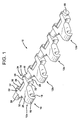
- the link section 10 includes a plurality of laterally repeating link-shaped portions 12a ... 12n, four of which (12a, 12b, 12c, 12d) are shown in the drawings for purposes of illustrating one possible embodiment of the invention.
- link-shaped portion 12a it can be seen that it includes a first projecting end or apex portion 14. This first end or apex portion 14 preferably leads when used in forming a conveyor belt or chain, although it will be understood from the description that follows that a belt or belt section formed of a plurality of the link sections 10a . . .
- the apex portion 14 includes a rounded nose 16 having a generally arcuate, rounded, or curved leading surface and a receiver 18, the details of which are provided in the description that follows.
- An upper surface 20 of the apex portion 14 when oriented as shown in Figure 1 may be substantially planar and, thus, forms a surface capable of engaging or assisting in supporting the articles or products being transported (or possibly for engaging a drive roller when a friction-type drive is used).
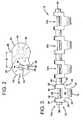
- At least two projections which may be in the form of leg portions 22, 24, project or extend from the apex portion 14.
- these leg portions 22, 24 include a generally planar upper surface 26 capable of engaging or assisting in supporting articles being conveyed.
- Each leg portion 22, 24 further includes an outer sidewall 28, an inner sidewall 30, a leading recessed portion 32, and a trailing portion 34.
- Both portions 32, 34 may be generally arcuate, rounded or curved.
- the curvature of the leading recessed portion 32 may generally match the curvature of the trailing portion 34, such that the outer surfaces of these portions cooperate or mate together in an interdigitating fashion without interference when two of the link sections 10 are interconnected and caused to pivot relative to one another.
- the first integral connector 36 may be a single, continuous, generally cylindrical piece of material that extends between and is integrally formed in the opposed inner sidewalls 30 of each leg portion 22, 24.
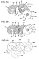
- the first connector 36 is spaced from a recessed portion 38 of the corresponding apex portion 14 (see Figure 6a). This recessed portion 38 is adapted for cooperating with the outer surface of the rounded nose 16 on the apex portion 14 of a next-adj acent link and, thus, is also generally arcuate, rounded or curved (see Figure 5).
- a second integral connector 40 extends between the outer walls 28 of the adjacent leg portions 22, 24 and, thus, connects the adjacent, substantially identical link-shaped portions 12a, 12b, 12c, 12d to form the unitary link section 10.
- the second integral connector 40 like the first one, may also be barrel-shaped or cylindrical, but may be oversized as compared to the first connector 36. In certain applications, this may be desirable to ensure that a strong connection is established between the adjacent link-like or link-shaped portions 12a ... 12n and that the article-carrying capabilities of the belt or chain are not compromised.
- this second connector 40 may be designed for engaging a tooth on a drive or idler sprocket, when such a structure is used to drive or guide a belt formed of the link sections 10a ... 10n.
- the connector need not have any particular shape or form.
- the receiver 18 may include an entryway 46 (preferably oversized, but at a minimum sufficient to accommodate the first connector 36) and a pair of opposed sidewalls 48.
- the sidewalls 48 may slope inwardly towards each other when viewed from the side and, thus, form a neck N through which a structure, such as the first integral connector 36 of an adjacent link, may pass to create a snap-fit engagement.
- This snap-fit engagement is one of the many advantageous features of this link section 10, since it creates a secure, strong connection while avoiding the need for the removable-type of transverse connector rod and locking tabs characteristic of many prior art proposals.
- the link section 10 can be provided as a single, unitary piece, which facilitates scaling it up or down, including possibly for use as part of a "micropitch” belt or chain. Assembly of a belt section (or chain section, the terms “belt” and “chain” being used interchangeably throughout) using the link sections 10 is also made less time consuming and less expensive, both of which are considered significant advantages.
- each apex portion 14 includes outer sidewalls 42 that may be tapered. Specifically, by comparing Figures 3 and 4, it is noted that these outer sidewalls 42 are tapered in two different vertically oriented planes, including: (1) a first taper having its widest extent at the portion of the apex portion 14 adjacent to the leg portions 22, 24 and tapering toward the nose portion 16 ( Figure 3); and (2) a second taper having its widest extent at the upper surface 20 of the apex portion 14 and tapering toward the underside surface 44 of the link section 10.
- each leg portion 22, 24 are also sloped so as match the taper of the sidewalls 42 (which in this case, makes the inner walls outwardly divergent). Consequently, when two of the link sections 10a, 10b are interconnected to form a belt section 50 (such as is shown in Figures 6-8 and described further below), smooth, relative pivoting movement may result. However, because of the taper and matching slope of the sidewalls 30, 42, the degree to which adjacent link sections 10a, 10b pivot relative to one another may be precisely controlled.
- a limit on the amount of pivoting movement that can be achieved by one link section 10a may be controlled by providing the outer sidewalls 42 of the apex portion 14 with a taper greater than or less than the slope of the corresponding inner sidewalls 30 of the next-adjacent link section 10b.
- Figure 6a shows that two link sections 10a, 10b may be interconnected by positioning the first integral connectors 36 on each link-like portion 12a ... 12d in the entryway 46 of the receiver 18 formed in each apex portion 14. It should be appreciated from Figure 6a that the protruding nature of the nose portion 16 may interfere with an overhang created by the combination of the upper surface 20 of the apex portion 14 and the arcuate recessed portion 38 formed adjacent thereto.
- the second link section 10b should be positioned at an angle relative to the first link section 10a. From this position, gentle finger pressure may then be applied to either or both of the link sections 10a, 10b (note action arrow A in Figure 6a) such that each first connector 36 passes along the tapered sidewalls 48 and past the neck N to form a secure, snap-fit engagement in the receiver 18 (see Figure 6b).
- the link sections 10a, 10b are fabricated of lightweight, low-cost wear-resistant plastics materials (Acetal, UHMW polypropylene, etc.). While these materials are generally rigid, the design of the apex portion 14 is such that the nose portion 16 is capable of flexing outwardly relative to the remainder of the link section 10a or 10b to at least a limited degree. Consequently, each first connector 36 may pass through the neck N with the application of only a moderate amount of force (such as finger pressure), yet remains securely captured once in place in the receiver 18 as a result of the "snap-back" action that occurs once the connector passes the neck.
- a moderate amount of force such as finger pressure
- first integral connector 36 with a smaller diameter relative to the second connector 40 may be a desirable feature, since it may allow for the corresponding receiver 18 to consume less of the material forming the apex portion 14 and may contribute to the overall strength of the link section 10.
- each receiver 18 is slightly oversized relative to the corresponding first connector 36. Accordingly, when the two link sections 10a, 10b are interconnected in snap-fit engagement, one is capable of pivoting relative to the other. Hence; once the desired snap-fit engagement is established between the receivers 18 and the corresponding first connectors 36, the next-adjacent link 10b is simply rotated into position, with the cooperating leading recess portion 32 and curved trailing surface 34 on the leg portions 22, 24 and the cooperating nose portion 16 and recessed portion 38 on the nested apex portions 14 freely moving relative to one another.
- the slight overhang that may optionally be created by the upper surface 20 of the apex portion 14 of the first or leading link section 10a advantageously serves to cover the arcuate or curved nose 16 of the apex portion 14 of the next-adjacent, second, or trailing link section 10b.
- an overhang may be created by the upper surface 26 of the leg portions 22, 24 of the second or trailing link 10b to partially cover the arcuate or curved trailing surface 34 of the leg portions 22, 24 of the next-adjacent, first, or leading link 10a.
- the result is a generally planar and substantially continuous conveying surface between the link-shaped portions 12 of link sections 10a, 10b capable of engaging, supporting, or assisting in supporting objects, such as products or articles being conveyed.
- the link sections 10a, 10b are capable of pivoting through a range of approximately 85° (from about positive 25° in the first quadrant to about negative 60° in the fourth quadrant (300° when measured from the horizontal or X-axis); note action arrow P in Figure 6c and the position of phantom link section 10a').
- increasing or decreasing this range is possible by changing the relative orientation of the matching sidewalls 30, 42.
- orienting the sidewalls 30, 42 generally perpendicular to a transverse axis and substantially parallel to each other may allow for a greater degree of pivoting movement.
- changing the taper of one sidewall 30, 42 without making a corresponding change to the other may serve to limit the degree of relative pivoting movement.
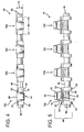
- each leg portion 22, 24 slopes or curves downwardly and then gently upwardly to form a rounded or bulbous lower surface 56 coextensive with the arcuate or curved rear or trailing portion 34.
- the resulting curved profile has a radius of curvature that matches that of the adjacent structure, such as nose bar B.
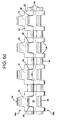
- Figure 8 shows the manner in which the teeth of a drive or idler sprocket S may engage the second integral connectors 40a, 40b on interconnected link sections 10a, 10b when a belt C formed of the links or link sections 10a ... 10n is driven or guided in this manner. While the conveyor belt C is shown as being driven with the apex portion 14 as the leading portion and the leg portions 22, 24 in the trailing position (note action arrow F), it should be appreciated that a belt formed of link sections 10a ... 10n is easily capable of being driven in the opposite direction by simply reversing the direction in which the sprocket S rotates.
- each second integral connector 40 may be driven along the return run, including by one or more sprockets (not shown) positioned external to the now-inverted "upper" surface 20 of the apex portion 14.
- sprockets not shown
- the use of tensioning/pinch rollers or like structures may be desirable to ensure that the belt engages the sprocket(s).
- any engagement roller contacting the underside surfaces 44, including the underside 56 of the leg portions 22, 24 at each end of the belt, or alternatively the upper surfaces 20, 26 along the return run, such as if tensioning rollers or the like are used (not shown).
- each link section 10 is shown as including an optional partial or truncated integral connector 58 projecting from the outer sidewall 28 of the outermost link-shaped portions 12a, 12d. While this feature is optional, it may provide several advantages when present, depending on the particular application. First of all, it provides a surface for abutting with a guide structure, such as a guide rail, sidewall, or the like.
- a corresponding connector 58 projecting from a laterally-adjacent link section (not shown) in situations where shorter link sections are "brick-layered" with longer link sections (not shown) (e.g., two link sections spaced laterally side-by-side, each with four laterally repeating link-shaped portions, coupled to an upstream unitary link section having eight laterally repeating link-shaped portions).
- the abutting connectors 58 not only cover the void that would otherwise exist between laterally adjacent link sections, but also provide a structure that may be engaged by a corresponding drive or idler sprocket positioned at the center of the longer link section (e.g., between the fourth and fifth link-shaped portions, in the case where there are eight total).
- the connector 58 may be sized and shaped to fit into and slide along a corresponding channel (not shown) formed in a guide structure, such as a sidewall supported by a support structure such as a conveyor frame.
- This type of arrangement can also be used in assisting in supporting a belt formed of the link sections 10a ... 10n along the return run of the conveyor, for providing guidance as it passes through an intermediate drive structure or the like, or for other types of arrangements where simultaneously capturing, guiding, and supporting a moving belt is necessary.
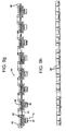
- Figure 9a-9j shows two different embodiments of link sections 10 having a high-friction conveying surface CS.
- Figures 9a-9e show a link section 10 with four laterally-repeating link-shaped portions 12a-12d
- Figures 9g-9j show one with eight laterally repeating portions 12a-12h.
- the two types of link sections 10 are thus readily adapted for being formed into a belt or chain C in a brick-layered fashion (e.g., 4+4, 8, 4+4, 8, etc.; 4+8+8, 8+8+4, 8+4+8, etc.).
- the high-friction surface may be formed by providing dimples or dimple-like projections 60 in at least part of the apex portion 14 (such as the upper surface 20) and the leg portions 22, 24 (such as the upper surface 26).
- the projections 60 may be formed integrally during the molding process, or may be provided on separate structures that are affixed to the link 10 (such as by co-molding or adhesives).
- Link sections 10 with projections 60 can also be combined with "regular" links or link sections to form a composite belt section.
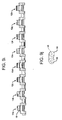
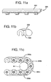
- each second connector 140 present is in the form of a flat article support surface, generally planar with the upper surfaces 126 of the leg portions 122, 124 (which may also be considered to comprise part of the article support surface), rather than a "barrel-like" portion that creates a gap in the conveying surface.
- a first end 130 of this portion is preferably rounded and the corresponding second end 132 includes a matching curved face having a contour adapted for engaging the rounded first end of a next-adjacent link when the two are connected in snap-fit engagement.
- the underside of this connector 140 may include a portion 142 adapted for being engaged by a drive or idler sprocket, which may be rounded similar to the underside of the second connector 40 (see Figure 5).
- the optional end stubs or truncated connectors 58 are also modified to include a flat-top portion 140 that completes the conveying surface.
- the flat-top portion 140 may also include the underside portion 142 adapted for engaging a drive or idler sprocket.
- the link 100 of this embodiment may also be provided with a high-friction conveying surface in the manner previously described.
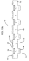
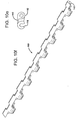
- FIGs 11a-11c show a "curved top" embodiment of a link 200.
- each link 200 may be substantially similar in construction to the flat top embodiment described above, but is provided with a substantially continuous, generally convex or bowed article conveying surface 202.
- the contour of this surface 202 may substantially match the contour of the underside portion 204 of the link 200 (which provides it with a kidney-shaped cross-section; see Figure 11b).
- the belt or chain C of this embodiment formed of the links 200 essentially behaves more like a piece of fabric or cloth passing the transfer than one formed of regular pitch links with a flat surface, which presents a varied or constantly changing surface to the bridge, transfer, or other structure.
- the convex conveying surface 202 may be unitary with each link section 200, or may be a provided on a separate component for attachment to a "regular" link section 10, 100, such as using welding, adhesives, snaps, or the like.
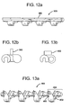
- Figures 12a and 12b show a version of the link 300 in which a generally upstanding cleat 302 forms part of the conveying surface.
- These links 300 may be spaced with other, non-cleated links to form a belt or belt section capable of selectively engaging and conveying articles of a particular type or size.
- links without cleats may be brick-layered with links 300 having cleats to form a specialized type of conveying surface for engaging and conveying a particular variety of articles.
- the cleats 302 may be unitary or otherwise.
- Figures 13 a and 13b show a link 400 with a raised top surface in which a pair of generally upstanding lugs 402 are provided on each laterally-repeating link section 404 or portion for assisting in engaging the articles being conveyed.
- the lugs 402 are generally oriented in the direction of travel, and may be angled slightly to improve their article-engaging capabilities.
- the use of brush top, scoop cleats, and laterally movable guides is also possible.
- the use of well-known types of co-molding techniques to include a resilient insert in the body of each link or link section having one or more outwardly extending, resilient fingers to form a high friction surface is also possible.
- each link section 10a, 10b preferably has a height H of approximately 6 millimeters (see Figure 4), and most preferably has a lesser height of about 4 millimeters.
- the width as measured from one end of the link-shaped portion 12d to the imaginary opposite end is about 15 millimeters (which, in the case of the exemplary link having a 4 millimeter height, makes the height to width ratio 1:3.75, and in the case of an exemplary link having a 6 millimeter height, makes this ratio 2.5).
- each of the laterally repeating link-shaped portions 12a-12d creates a link section 10 approximately 60 millimeters wide, and eight create a link section approximately 120 millimeters wide.
- the distance from about the center of the receiver 18 to about the center of the first connector 36 is most preferably 5 millimeters.
- the "height-to-pitch" ratio of a link (H/D) having this preferred range of dimensions is about 1 when speaking in terms of one significant figure and, more specifically, from about 0.8 (4 millimeters/5 millimeters) to about 1.2 (6 millimeters/5 millimeters) when speaking in terms of two significant figures.
- a conveyor belt or chain C formed of the link sections 10a ... 10n may be supported and guided using any conventional arrangement, including well-known types of support beds, rails, or the like.
- stub connectors 58 it is also possible to adapt the ends of the link section 10 to include depending side arms with inwardly projecting guide tabs for engaging a guide rail (not shown), as disclosed in the commonly assigned '693 and '757 patents.
- a "regular" sized, non-"micropitch" link formed in accordance with the teachings of the present application is more amenable to having these types of depending and inwardly projecting structures, since weakening due to the smaller dimensions may be less of a concern.
- second integral connectors 40 may also be adjusted as necessary or desired to achieve a particular purpose. For example, in the case where there are four link-shaped portions 12a-12d, it is possible to provide a second integral connector 40 between portions 12a and 12b and between portions 12c and 12d, each for engaging a corresponding drive or idler sprocket. Portions 12b and 12c can simply be merged together at the interface between the outer sidewalls 28 of the corresponding leg portions 22, 24 (not shown). In cases where a belt formed of the link sections 10a ... 10n is not sprocket-driven, the second integral connectors 40 couldbe eliminated altogether, with the adjacent leg portions 22, 24 simply being merged together. However, in terms of ease of belt design and manufacturing flexibility, it is preferable to create symmetrical link sections 10a.... 10n that laterally repeat with the same predictable frequency.
- the relative size and width of the apex portion 14 and the leg portions 22, 24 may also be changed as necessary to achieve a particular result. For example, in the case where a slightly stronger link section is required, it may be beneficial to widen the leg portions 22, 24 and shorten the apex portion 14 in the transverse or width dimension.
- the sizes, shapes, and relative orientations of the receiver 18 and the connectors 36, 40 may also be changed as necessary, such as to strengthen the link section 10 or achieve any other desired result.
- the use of integral connectors in place of the conventional stainless steel connector rods may substantially reduce the weight of the resulting belt or chain C. This generally means that less support and driving force are required for a chain formed of these links or link sections 10, as compared to one having stainless steel connector rods.
- the connector may comprise two opposed, spaced stub shafts (not shown, but see partial projection 58) that project inwardly from each sidewall 30.
- the receiver 18 may be divided by a wall or partition (not shown) into two receivers, one of which receives each stub shaft comprising the integral connector 36.
- the wall or partition does serve to strengthen the resulting link section 10, but is generally considered optional.
- This embodiment is somewhat less preferred, since the opposed stub shafts are considerably weaker than the continuous connector 36, especially in the "micropitch" arrangement.
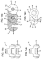
- links formed having the dimensions disclosed herein to create a "micropitch" belt it is possible to provide only one link-shaped portion 12 that interconnects with the link-shaped portions of first and second adjacent links or link sections 10a, 10b in snap-fit engagement to form a narrow-width belt or chain C.
- Examples of such a link 10 and a chain C formed of links 10a, 10b are shown in Figures 14a, 14b, 14c, and 14d.
- a plurality of belts or chains formed of such links may then be arranged side-by-side and gang driven to create the conveyor.
Landscapes
- Engineering & Computer Science (AREA)
- Mechanical Engineering (AREA)
- Chain Conveyers (AREA)
- Belt Conveyors (AREA)
- Compositions Of Macromolecular Compounds (AREA)
- Package Frames And Binding Bands (AREA)
- Lubricants (AREA)
- Structure Of Belt Conveyors (AREA)
Priority Applications (1)
| Application Number | Priority Date | Filing Date | Title |
|---|---|---|---|
| EP07018250A EP1911694A3 (en) | 2002-02-26 | 2003-02-26 | Rodless conveyor belt or chain |
Applications Claiming Priority (7)
| Application Number | Priority Date | Filing Date | Title |
|---|---|---|---|
| US35958202P | 2002-02-26 | 2002-02-26 | |
| US359582P | 2002-02-26 | ||
| US42306702P | 2002-11-01 | 2002-11-01 | |
| US423067P | 2002-11-01 | ||
| US43522102P | 2002-12-18 | 2002-12-18 | |
| US435221P | 2002-12-18 | ||
| PCT/US2003/005666 WO2003072464A1 (en) | 2002-02-26 | 2003-02-26 | Rodless conveyor belt or chain |
Related Child Applications (1)
| Application Number | Title | Priority Date | Filing Date |
|---|---|---|---|
| EP07018250A Division EP1911694A3 (en) | 2002-02-26 | 2003-02-26 | Rodless conveyor belt or chain |
Publications (3)
| Publication Number | Publication Date |
|---|---|
| EP1487723A1 EP1487723A1 (en) | 2004-12-22 |
| EP1487723A4 EP1487723A4 (en) | 2006-01-18 |
| EP1487723B1 true EP1487723B1 (en) | 2007-12-19 |
Family
ID=27767847
Family Applications (1)
| Application Number | Title | Priority Date | Filing Date |
|---|---|---|---|
| EP03711243A Expired - Lifetime EP1487723B1 (en) | 2002-02-26 | 2003-02-26 | Rodless conveyor belt or chain |
Country Status (10)
| Country | Link |
|---|---|
| US (2) | US7314132B2 (ja) |
| EP (1) | EP1487723B1 (ja) |
| JP (1) | JP4445269B2 (ja) |
| AT (1) | ATE381502T1 (ja) |
| AU (1) | AU2003213562A1 (ja) |
| CA (1) | CA2477145C (ja) |
| DE (1) | DE60318187T2 (ja) |
| DK (1) | DK1487723T3 (ja) |
| MX (1) | MXPA04008160A (ja) |
| WO (1) | WO2003072464A1 (ja) |
Cited By (1)
| Publication number | Priority date | Publication date | Assignee | Title |
|---|---|---|---|---|
| WO2021141883A1 (en) * | 2020-01-06 | 2021-07-15 | Laitram, L.L.C. | Modular conveyor belt with dedicated access assembly |
Families Citing this family (48)
| Publication number | Priority date | Publication date | Assignee | Title |
|---|---|---|---|---|
| US6959803B1 (en) * | 2002-12-18 | 2005-11-01 | Span Tech Llc | Self-tensioning conveyor |
| WO2005040016A1 (en) * | 2003-10-23 | 2005-05-06 | Joan Anton Halbesma | Flexible conveyor for conveying exceptionally heavy loads |
| EP1588958A3 (en) * | 2004-04-22 | 2006-03-22 | uni-chains A/S | Clean Belt |
| US20060051511A1 (en) * | 2004-08-13 | 2006-03-09 | Orosz Gary R | Apparatus and systems for coating objects |
| US7278535B2 (en) * | 2004-11-10 | 2007-10-09 | Ped Invest A/S | Net belt |
| ES2265293B1 (es) * | 2005-07-28 | 2008-02-16 | Thyssenkrupp Norte, S.A. | Pasillo movil. |
| NL1030155C2 (nl) * | 2005-10-10 | 2007-04-11 | Rexnord Flattop Europe Bv | Transporteur. |
| US7517270B2 (en) * | 2006-05-30 | 2009-04-14 | Minds-I, Inc. | Construction system |
| US20080075528A1 (en) * | 2006-09-22 | 2008-03-27 | Michael Marzetta | Construction system |
| US7410225B1 (en) * | 2007-03-14 | 2008-08-12 | Minds-I, Inc. | Multi-part links for endless track |
| US7360644B1 (en) | 2007-03-23 | 2008-04-22 | Habasit Ag | Modular belt with rodless hinge |
| ES2283237B1 (es) | 2007-04-23 | 2008-08-01 | Angel Carmelo San Miguel Zarzuela | Eslabon para cadenas transportadoras y cadena obtenida con el mismo. |
| US20090017716A1 (en) * | 2007-07-11 | 2009-01-15 | Michael Marzetta | Construction system |
| US7874419B2 (en) * | 2007-07-19 | 2011-01-25 | Dorner Mfg. Corp. | Contained drive system for chain conveyor belt to reduce catenary sag |
| US7841923B2 (en) * | 2007-11-13 | 2010-11-30 | Minds-I, Inc. | Vehicle axle joint for a toy vehicle |
| US7624858B2 (en) * | 2007-12-21 | 2009-12-01 | Habasit Ag | Modular plastic conveyor belt for spiral conversion |
| US7635060B2 (en) * | 2008-02-06 | 2009-12-22 | Laitram, L.L.C. | Apparatus and method for sensing conditions local to a modular conveyor belt |
| US8042597B2 (en) * | 2009-04-27 | 2011-10-25 | Lutron Electronics Co., Inc. | Roller shade system having hembar for pleating a shade fabric |
| US8113340B1 (en) | 2009-02-03 | 2012-02-14 | Hormel Foods Corporation | Modular conveyer belt |
| DE102009020304A1 (de) * | 2009-05-07 | 2010-11-25 | Hastem-Müller, Stefan | Glied für ein Gliederband |
| JP2011172766A (ja) * | 2010-02-24 | 2011-09-08 | Fujifilm Corp | トルク伝達デバイス |
| US8522961B2 (en) * | 2010-08-19 | 2013-09-03 | Laitram, L.L.C. | Two-material conveyor belt module |
| DK177377B1 (en) * | 2011-07-05 | 2013-02-25 | Ammeraal Beltech Modular As | Modular belt module |
| DE102012103078A1 (de) * | 2012-04-10 | 2013-10-10 | Krones Ag | Kettenförderer für Kunststoffvorformlinge |
| US9102476B2 (en) | 2012-10-25 | 2015-08-11 | Solus Industrial Innovations, Llc | Conveyor system wear indication devices and methods |
| WO2014085688A2 (en) | 2012-11-29 | 2014-06-05 | Emerson Electric Company | Side-flexing conveyors |
| NL2011934C2 (en) * | 2013-12-10 | 2015-06-11 | Rexnord Flattop Europe Bv | Module for a conveyor chain and modular conveyor chain. |
| US9663298B2 (en) * | 2014-12-18 | 2017-05-30 | Laitram, L.L.C. | Conveyor belt module with shaped bottom surface |
| IL243145B (en) * | 2014-12-24 | 2019-06-30 | System and methods for assembling chain links using a coupling mechanism | |
| US10464757B2 (en) | 2014-12-31 | 2019-11-05 | Prince Castle LLC | Sprocket driven conveyor belt link and conveyor belt assembly |
| US10315847B2 (en) | 2014-12-31 | 2019-06-11 | Prince Castle LLC | Extruded slat/link conveyance chain |
| NL2014355B1 (en) * | 2015-02-26 | 2016-10-13 | Kaak Groep B V | Linked conveyor belt and method of manufacturing a linked conveyor belt. |
| US9889992B1 (en) | 2015-05-13 | 2018-02-13 | Prince Castle LLC | Conveyor belt slat |
| US9908708B1 (en) | 2015-05-13 | 2018-03-06 | Prince Castle LLC | Conveyor belt link with coupling mechanism |
| US10752446B2 (en) * | 2015-09-25 | 2020-08-25 | Habasit Ag | Hybrid modular belt |
| EP3199477B1 (en) | 2016-01-27 | 2019-07-17 | Prince Castle LLC | A slat for a chain conveyor belt and a conveyor belt system comprising the same |
| USD804137S1 (en) * | 2016-02-23 | 2017-11-28 | Span Tech Llc | Conveyor link |
| US10308433B2 (en) | 2016-06-29 | 2019-06-04 | Prince Castle LLC | Conveyor belt slat with side carrier connection |
| US20180000284A1 (en) * | 2016-06-29 | 2018-01-04 | Prince Castle LLC | Continuous conveyor belt for food heating device |
| US10723560B2 (en) | 2016-11-18 | 2020-07-28 | Prince Castle LLC | Side-by-side snap on slats for a chain conveyor belt and conveyor belt system comprising same |
| DE102017113096A1 (de) * | 2017-06-14 | 2018-12-20 | Ketten-Wulf Betriebs-Gmbh | Modulares Förderband |
| US10919703B2 (en) * | 2017-07-10 | 2021-02-16 | Laitram, L.L.C. | Belt conveyor and modular conveyor belt for inclines |
| US10843871B2 (en) | 2017-12-01 | 2020-11-24 | Prince Castle LLC | Side-by-side slats for a chain conveyor belt and conveyor belt system comprising same |
| CN108482944B (zh) * | 2018-03-30 | 2024-01-02 | 浙江工业职业技术学院 | 一种双辊转弯输送机 |
| EP3921253A4 (en) | 2019-02-06 | 2022-11-30 | Laitram, L.L.C. | MODULAR CONVEYOR BELT WITH HOOK HINGES |
| US11279563B2 (en) * | 2019-12-17 | 2022-03-22 | Cambridge International, Inc. | Systems and methods for a wire plate conveyor belt |
| USD919922S1 (en) | 2019-12-17 | 2021-05-18 | Cambridge International, Inc. | Conveyor belt |
| USD998059S1 (en) * | 2021-07-14 | 2023-09-05 | Jinfeng Cai | Marble run toy |
Family Cites Families (59)
| Publication number | Priority date | Publication date | Assignee | Title |
|---|---|---|---|---|
| US382554A (en) | 1888-05-08 | Detachable-link chain | ||
| US237591A (en) | 1881-02-08 | Detachable drive-chain | ||
| US377120A (en) | 1888-01-31 | Drive-chain | ||
| US2695095A (en) * | 1950-12-05 | 1954-11-23 | Mathews Conveyer Co | Conveyer chain link |
| US3069923A (en) | 1960-11-17 | 1962-12-25 | Kropp Forge Co | Link member |
| DE1183014B (de) * | 1961-04-20 | 1964-12-03 | Alfred Schmermund | Presskette zum Zufuehren von Tabak, z. B. zu Tabakschneidern |
| US3160024A (en) | 1964-05-05 | 1964-12-08 | Oliver W Mojonnier | Link member |
| US3415136A (en) | 1967-03-13 | 1968-12-10 | Oliver W. Mojonnier | Link chain |
| US3513965A (en) | 1968-10-21 | 1970-05-26 | Eldon S Miller | Conveyor and link |
| US3628834A (en) | 1969-09-03 | 1971-12-21 | Baychem Corp | Link members and endless chains especially for tracked vehicles |
| NL7202250A (ja) | 1972-02-21 | 1973-08-23 | ||
| FR2214244A5 (ja) | 1973-01-13 | 1974-08-09 | Fischer Artur | |
| FR2279047A1 (fr) | 1974-07-19 | 1976-02-13 | Ugine Carbone | Nouvelle sole de four |
| DE2909893C2 (de) * | 1979-03-14 | 1982-07-29 | Heinrich Schlick KG, GmbH & Co, 4402 Greven | Band für eine Muldenband-Reinigungsvorrichtung |
| US4815270A (en) | 1980-11-26 | 1989-03-28 | Lapeyre James M | Detachable link chain |
| US4473365A (en) | 1980-11-26 | 1984-09-25 | Lapeyre James M | Detachable link chain |
| US4815271A (en) | 1980-11-26 | 1989-03-28 | The Laitram Corporation | Detachable link chain |
| US4597747A (en) | 1980-11-26 | 1986-07-01 | The Laitram Corporation | Detachable link chain |
| US4882901A (en) | 1980-11-26 | 1989-11-28 | The Laitram Corporation | Detachable link chain |
| US4394901A (en) | 1980-12-16 | 1983-07-26 | Ashworth Bros., Inc. | Modular plastic conveyor belt |
| NZ211988A (en) | 1985-05-06 | 1990-12-21 | Napier Tool & Die Co | Conveyor belt element; elements join to make up endless conveyor without need for separate pin |
| USD307707S (en) | 1987-01-29 | 1990-05-08 | Ab Skf | Conveyor chain link |
| US4953693A (en) | 1989-01-23 | 1990-09-04 | Span Tech Corporation | Modular link conveyor system |
| US4951457A (en) | 1989-11-08 | 1990-08-28 | Deal Douglas O | Narrow pitch articulated chain and links therefor |
| US5031757A (en) | 1989-12-26 | 1991-07-16 | Span Tech Corporation | Modular link conveyor system with narrow chain |
| US5181601A (en) | 1990-10-09 | 1993-01-26 | Palmaer K V | Plastic conveyor belt with integral sideplate |
| SE9004102D0 (sv) | 1990-12-21 | 1990-12-21 | Skf Specialty Product Ab | Plastkedja och monterbar laasningslaepp respektive styrtapp |
| US5197591A (en) * | 1992-02-11 | 1993-03-30 | Ashworth Bros., Inc. | Replaceable snap-on modular overlay for rod and link turn-curve conveyor belts |
| US5125504A (en) * | 1991-03-08 | 1992-06-30 | Rexnord Corporation | Modular conveyor chain having open hinge pin construction |
| US5215185A (en) | 1992-09-08 | 1993-06-01 | Rexnord Corporation | Breakable molded plastic links for forming conveyor chain |
| US5562200A (en) | 1994-03-25 | 1996-10-08 | Maryland Wire Belts, Inc. | Unitary components and modular belt assembly |
| NL9301355A (nl) | 1993-08-03 | 1995-03-01 | Mcc Nederland | Uit kunststof modules opgebouwde transportmat en modules voor een dergelijke transportmat. |
| US5346060A (en) | 1993-08-31 | 1994-09-13 | Precision Handling Devices, Inc. | Link assemblies which are interconnected to provide a self-tensioning conveyor belt |
| GB2282115A (en) | 1993-09-22 | 1995-03-29 | Kelvin Taylor Robertson | Interconnecting conveyor modules |
| US5797820A (en) | 1995-09-22 | 1998-08-25 | Yamakyu Chain Co., Ltd. | Slat band chain and sprocket |
| NL1002501C2 (nl) * | 1996-03-01 | 1997-09-03 | Mcc Nederland | Kunststof module voor een transportmat. |
| US6223889B1 (en) | 1996-06-10 | 2001-05-01 | Span Tech Llc | Modular link conveyor with interdigitating grid and interleaving side wings |
| US5967296A (en) | 1997-03-06 | 1999-10-19 | Dolan; Rex H. | Transfer conveyor |
| US5964340A (en) | 1997-03-06 | 1999-10-12 | Dolan; Rex H. | Transfer conveyor |
| USD427898S (en) | 1997-04-02 | 2000-07-11 | Sinapore Technologies Automotive Limited | Tracked link body |
| USD420483S (en) | 1997-10-06 | 2000-02-08 | Flexlink Systems Ab | Chain-link to a conveyor |
| USD419742S (en) | 1997-10-06 | 2000-01-25 | Flexlink Systems Ab | Chain-link to a conveyor |
| US6158575A (en) | 1998-04-28 | 2000-12-12 | Berg Technology, Inc. | Links for forming a connector transport chain |
| US6138820A (en) * | 1998-05-15 | 2000-10-31 | Westar Mfg. Corp. | Conveyor chain link |
| JP2000072214A (ja) | 1998-08-31 | 2000-03-07 | Tsubakimoto Chain Co | 低摩擦樹脂製コンベヤチェーン |
| GB9920932D0 (en) | 1999-09-03 | 1999-11-10 | Boc Group Plc | Chain clamp |
| US6347699B1 (en) * | 1999-11-08 | 2002-02-19 | Earl Ramsey | Conveyor chain link |
| JP3448255B2 (ja) | 2000-03-24 | 2003-09-22 | 株式会社椿本チエイン | 直交荷渡しコンベヤに用いる搬送用チェーン |
| US6364095B1 (en) | 2000-04-13 | 2002-04-02 | Span Tech Llc | Modular conveyor system with side flexing belt having roller support |
| US6305530B1 (en) | 2000-05-30 | 2001-10-23 | Habasit Ag | Module for a modular conveying belt |
| US6382404B1 (en) | 2000-12-21 | 2002-05-07 | Habasit Ag | Corrugated flight module |
| US6732856B2 (en) | 2001-02-27 | 2004-05-11 | Maryland Wire Belts, Inc. | Modular conveyor belt |
| US6443795B1 (en) | 2001-09-11 | 2002-09-03 | Wen-Pin Lin | Transmission chain for toys |
| USD473032S1 (en) | 2002-01-15 | 2003-04-08 | Larry Altom | Modular plastic conveyor belt component |
| USD483168S1 (en) | 2002-08-13 | 2003-12-02 | Span Tech Llc | Modular guide link for conveyor chain |
| US6874617B1 (en) * | 2003-09-26 | 2005-04-05 | Span Tech Llc | Modular link conveyor chain with rotatable article engaging assemblies |
| US7108126B2 (en) * | 2003-12-10 | 2006-09-19 | Span Tech, Llc | Side-flexing conveyor chain having twin transverse connectors |
| US7367447B1 (en) * | 2006-11-03 | 2008-05-06 | Habasit Ag | Rodless modular conveyor belt |
| US7360644B1 (en) * | 2007-03-23 | 2008-04-22 | Habasit Ag | Modular belt with rodless hinge |
-
2003
- 2003-02-26 EP EP03711243A patent/EP1487723B1/en not_active Expired - Lifetime
- 2003-02-26 DE DE60318187T patent/DE60318187T2/de not_active Expired - Lifetime
- 2003-02-26 AU AU2003213562A patent/AU2003213562A1/en not_active Abandoned
- 2003-02-26 WO PCT/US2003/005666 patent/WO2003072464A1/en active IP Right Grant
- 2003-02-26 AT AT03711243T patent/ATE381502T1/de active
- 2003-02-26 MX MXPA04008160A patent/MXPA04008160A/es active IP Right Grant
- 2003-02-26 JP JP2003571180A patent/JP4445269B2/ja not_active Expired - Fee Related
- 2003-02-26 CA CA2477145A patent/CA2477145C/en not_active Expired - Fee Related
- 2003-02-26 US US10/505,943 patent/US7314132B2/en not_active Expired - Lifetime
- 2003-02-26 DK DK03711243T patent/DK1487723T3/da active
-
2007
- 2007-08-15 US US11/839,284 patent/US7559422B2/en not_active Expired - Lifetime
Cited By (2)
| Publication number | Priority date | Publication date | Assignee | Title |
|---|---|---|---|---|
| WO2021141883A1 (en) * | 2020-01-06 | 2021-07-15 | Laitram, L.L.C. | Modular conveyor belt with dedicated access assembly |
| EP4087798A4 (en) * | 2020-01-06 | 2024-05-15 | Laitram Llc | MODULAR CONVEYOR BELT WITH OWN ACCESS ARRANGEMENT |
Also Published As
| Publication number | Publication date |
|---|---|
| AU2003213562A1 (en) | 2003-09-09 |
| CA2477145C (en) | 2011-04-05 |
| EP1487723A4 (en) | 2006-01-18 |
| US20080023303A1 (en) | 2008-01-31 |
| US7314132B2 (en) | 2008-01-01 |
| DE60318187D1 (de) | 2008-01-31 |
| JP2005518322A (ja) | 2005-06-23 |
| EP1487723A1 (en) | 2004-12-22 |
| WO2003072464A8 (en) | 2003-12-18 |
| ATE381502T1 (de) | 2008-01-15 |
| DK1487723T3 (da) | 2008-04-28 |
| WO2003072464A1 (en) | 2003-09-04 |
| MXPA04008160A (es) | 2005-06-08 |
| US7559422B2 (en) | 2009-07-14 |
| JP4445269B2 (ja) | 2010-04-07 |
| US20050067262A1 (en) | 2005-03-31 |
| DE60318187T2 (de) | 2008-12-04 |
| CA2477145A1 (en) | 2003-09-04 |
Similar Documents
| Publication | Publication Date | Title |
|---|---|---|
| EP1487723B1 (en) | Rodless conveyor belt or chain | |
| EP1154941B1 (en) | Modular belt with tapered oblong hinge pins | |
| US8210341B2 (en) | Conveyor transfer system with floating transfer platform | |
| US5775480A (en) | Low-friction conveyor assembly | |
| US4909380A (en) | Low backline pressure chain | |
| JP5379691B2 (ja) | モジュール間に支持されたローラを備える搬送ベルト | |
| KR100327962B1 (ko) | 방사형콘베이어벨트 | |
| CA2016155C (en) | Flat top conveyor | |
| US3854575A (en) | Conveyor belt system | |
| US6578704B1 (en) | Belts and belt modules for spiral conveyors | |
| US5330045A (en) | Low backline pressure chain | |
| AU2007265273B2 (en) | Roller-belt conveyor with infeed pull-away | |
| KR20080004542A (ko) | 컨베이어 및 모듈형 컨베이어 벨트 | |
| CN209922175U (zh) | 一种缝隙紧密的输送结构 | |
| US7527145B2 (en) | Low-friction conveyor | |
| EP1911694A1 (en) | Rodless conveyor belt or chain | |
| US11186439B2 (en) | Chain conveyor curve | |
| US20060175181A1 (en) | Reduced friction roller support for modular link conveyor chain | |
| EP3261962B1 (en) | Modular link conveyor with features for enhancing the efficient conveyance of articles | |
| CA1215016A (en) | Low backline pressure chain |
Legal Events
| Date | Code | Title | Description |
|---|---|---|---|
| PUAI | Public reference made under article 153(3) epc to a published international application that has entered the european phase |
Free format text: ORIGINAL CODE: 0009012 |
|
| 17P | Request for examination filed |
Effective date: 20040915 |
|
| AK | Designated contracting states |
Kind code of ref document: A1 Designated state(s): AT BE BG CH CY CZ DE DK EE ES FI FR GB GR HU IE IT LI LU MC NL PT SE SI SK TR |
|
| AX | Request for extension of the european patent |
Extension state: AL LT LV MK RO |
|
| A4 | Supplementary search report drawn up and despatched |
Effective date: 20051207 |
|
| GRAP | Despatch of communication of intention to grant a patent |
Free format text: ORIGINAL CODE: EPIDOSNIGR1 |
|
| RIN1 | Information on inventor provided before grant (corrected) |
Inventor name: LAYNE, JAMES, L. Inventor name: JOHNSON, MARK, T. Inventor name: DRAEBEL, OTTO, JORGEN Inventor name: MCDANIEL, MAICHEL, D. |
|
| GRAS | Grant fee paid |
Free format text: ORIGINAL CODE: EPIDOSNIGR3 |
|
| GRAA | (expected) grant |
Free format text: ORIGINAL CODE: 0009210 |
|
| AK | Designated contracting states |
Kind code of ref document: B1 Designated state(s): AT BE BG CH CY CZ DE DK EE ES FI FR GB GR HU IE IT LI LU MC NL PT SE SI SK TR |
|
| REG | Reference to a national code |
Ref country code: GB Ref legal event code: FG4D |
|
| REG | Reference to a national code |
Ref country code: IE Ref legal event code: FG4D |
|
| REG | Reference to a national code |
Ref country code: CH Ref legal event code: EP |
|
| REF | Corresponds to: |
Ref document number: 60318187 Country of ref document: DE Date of ref document: 20080131 Kind code of ref document: P |
|
| REG | Reference to a national code |
Ref country code: DK Ref legal event code: T3 |
|
| PG25 | Lapsed in a contracting state [announced via postgrant information from national office to epo] |
Ref country code: SE Free format text: LAPSE BECAUSE OF FAILURE TO SUBMIT A TRANSLATION OF THE DESCRIPTION OR TO PAY THE FEE WITHIN THE PRESCRIBED TIME-LIMIT Effective date: 20080319 Ref country code: LI Free format text: LAPSE BECAUSE OF FAILURE TO SUBMIT A TRANSLATION OF THE DESCRIPTION OR TO PAY THE FEE WITHIN THE PRESCRIBED TIME-LIMIT Effective date: 20071219 Ref country code: CH Free format text: LAPSE BECAUSE OF FAILURE TO SUBMIT A TRANSLATION OF THE DESCRIPTION OR TO PAY THE FEE WITHIN THE PRESCRIBED TIME-LIMIT Effective date: 20071219 |
|
| PG25 | Lapsed in a contracting state [announced via postgrant information from national office to epo] |
Ref country code: FI Free format text: LAPSE BECAUSE OF FAILURE TO SUBMIT A TRANSLATION OF THE DESCRIPTION OR TO PAY THE FEE WITHIN THE PRESCRIBED TIME-LIMIT Effective date: 20071219 Ref country code: NL Free format text: LAPSE BECAUSE OF FAILURE TO SUBMIT A TRANSLATION OF THE DESCRIPTION OR TO PAY THE FEE WITHIN THE PRESCRIBED TIME-LIMIT Effective date: 20071219 Ref country code: SI Free format text: LAPSE BECAUSE OF FAILURE TO SUBMIT A TRANSLATION OF THE DESCRIPTION OR TO PAY THE FEE WITHIN THE PRESCRIBED TIME-LIMIT Effective date: 20071219 |
|
| NLV1 | Nl: lapsed or annulled due to failure to fulfill the requirements of art. 29p and 29m of the patents act | ||
| REG | Reference to a national code |
Ref country code: CH Ref legal event code: PL |
|
| PG25 | Lapsed in a contracting state [announced via postgrant information from national office to epo] |
Ref country code: ES Free format text: LAPSE BECAUSE OF FAILURE TO SUBMIT A TRANSLATION OF THE DESCRIPTION OR TO PAY THE FEE WITHIN THE PRESCRIBED TIME-LIMIT Effective date: 20080330 Ref country code: CZ Free format text: LAPSE BECAUSE OF FAILURE TO SUBMIT A TRANSLATION OF THE DESCRIPTION OR TO PAY THE FEE WITHIN THE PRESCRIBED TIME-LIMIT Effective date: 20071219 |
|
| ET | Fr: translation filed | ||
| PG25 | Lapsed in a contracting state [announced via postgrant information from national office to epo] |
Ref country code: SK Free format text: LAPSE BECAUSE OF FAILURE TO SUBMIT A TRANSLATION OF THE DESCRIPTION OR TO PAY THE FEE WITHIN THE PRESCRIBED TIME-LIMIT Effective date: 20071219 Ref country code: BE Free format text: LAPSE BECAUSE OF FAILURE TO SUBMIT A TRANSLATION OF THE DESCRIPTION OR TO PAY THE FEE WITHIN THE PRESCRIBED TIME-LIMIT Effective date: 20071219 |
|
| PG25 | Lapsed in a contracting state [announced via postgrant information from national office to epo] |
Ref country code: PT Free format text: LAPSE BECAUSE OF FAILURE TO SUBMIT A TRANSLATION OF THE DESCRIPTION OR TO PAY THE FEE WITHIN THE PRESCRIBED TIME-LIMIT Effective date: 20080519 |
|
| PLBE | No opposition filed within time limit |
Free format text: ORIGINAL CODE: 0009261 |
|
| STAA | Information on the status of an ep patent application or granted ep patent |
Free format text: STATUS: NO OPPOSITION FILED WITHIN TIME LIMIT |
|
| PG25 | Lapsed in a contracting state [announced via postgrant information from national office to epo] |
Ref country code: MC Free format text: LAPSE BECAUSE OF NON-PAYMENT OF DUE FEES Effective date: 20080228 |
|
| 26N | No opposition filed |
Effective date: 20080922 |
|
| PG25 | Lapsed in a contracting state [announced via postgrant information from national office to epo] |
Ref country code: IE Free format text: LAPSE BECAUSE OF NON-PAYMENT OF DUE FEES Effective date: 20080226 Ref country code: GR Free format text: LAPSE BECAUSE OF FAILURE TO SUBMIT A TRANSLATION OF THE DESCRIPTION OR TO PAY THE FEE WITHIN THE PRESCRIBED TIME-LIMIT Effective date: 20080320 Ref country code: EE Free format text: LAPSE BECAUSE OF FAILURE TO SUBMIT A TRANSLATION OF THE DESCRIPTION OR TO PAY THE FEE WITHIN THE PRESCRIBED TIME-LIMIT Effective date: 20071219 |
|
| PG25 | Lapsed in a contracting state [announced via postgrant information from national office to epo] |
Ref country code: BG Free format text: LAPSE BECAUSE OF FAILURE TO SUBMIT A TRANSLATION OF THE DESCRIPTION OR TO PAY THE FEE WITHIN THE PRESCRIBED TIME-LIMIT Effective date: 20080319 |
|
| PG25 | Lapsed in a contracting state [announced via postgrant information from national office to epo] |
Ref country code: CY Free format text: LAPSE BECAUSE OF FAILURE TO SUBMIT A TRANSLATION OF THE DESCRIPTION OR TO PAY THE FEE WITHIN THE PRESCRIBED TIME-LIMIT Effective date: 20071219 |
|
| PG25 | Lapsed in a contracting state [announced via postgrant information from national office to epo] |
Ref country code: LU Free format text: LAPSE BECAUSE OF NON-PAYMENT OF DUE FEES Effective date: 20080226 Ref country code: HU Free format text: LAPSE BECAUSE OF FAILURE TO SUBMIT A TRANSLATION OF THE DESCRIPTION OR TO PAY THE FEE WITHIN THE PRESCRIBED TIME-LIMIT Effective date: 20080620 |
|
| PG25 | Lapsed in a contracting state [announced via postgrant information from national office to epo] |
Ref country code: TR Free format text: LAPSE BECAUSE OF FAILURE TO SUBMIT A TRANSLATION OF THE DESCRIPTION OR TO PAY THE FEE WITHIN THE PRESCRIBED TIME-LIMIT Effective date: 20071219 |
|
| PG25 | Lapsed in a contracting state [announced via postgrant information from national office to epo] |
Ref country code: IT Free format text: LAPSE BECAUSE OF NON-PAYMENT OF DUE FEES Effective date: 20080229 |
|
| PGFP | Annual fee paid to national office [announced via postgrant information from national office to epo] |
Ref country code: GB Payment date: 20130218 Year of fee payment: 11 Ref country code: DE Payment date: 20130219 Year of fee payment: 11 Ref country code: FR Payment date: 20130301 Year of fee payment: 11 Ref country code: DK Payment date: 20130218 Year of fee payment: 11 |
|
| PGFP | Annual fee paid to national office [announced via postgrant information from national office to epo] |
Ref country code: AT Payment date: 20130213 Year of fee payment: 11 |
|
| REG | Reference to a national code |
Ref country code: DE Ref legal event code: R119 Ref document number: 60318187 Country of ref document: DE |
|
| REG | Reference to a national code |
Ref country code: DK Ref legal event code: EBP Effective date: 20140228 |
|
| REG | Reference to a national code |
Ref country code: AT Ref legal event code: MM01 Ref document number: 381502 Country of ref document: AT Kind code of ref document: T Effective date: 20140226 |
|
| GBPC | Gb: european patent ceased through non-payment of renewal fee |
Effective date: 20140226 |
|
| REG | Reference to a national code |
Ref country code: FR Ref legal event code: ST Effective date: 20141031 |
|
| PG25 | Lapsed in a contracting state [announced via postgrant information from national office to epo] |
Ref country code: AT Free format text: LAPSE BECAUSE OF NON-PAYMENT OF DUE FEES Effective date: 20140226 |
|
| REG | Reference to a national code |
Ref country code: DE Ref legal event code: R119 Ref document number: 60318187 Country of ref document: DE Effective date: 20140902 |
|
| PG25 | Lapsed in a contracting state [announced via postgrant information from national office to epo] |
Ref country code: DK Free format text: LAPSE BECAUSE OF NON-PAYMENT OF DUE FEES Effective date: 20140228 Ref country code: DE Free format text: LAPSE BECAUSE OF NON-PAYMENT OF DUE FEES Effective date: 20140902 Ref country code: FR Free format text: LAPSE BECAUSE OF NON-PAYMENT OF DUE FEES Effective date: 20140228 Ref country code: GB Free format text: LAPSE BECAUSE OF NON-PAYMENT OF DUE FEES Effective date: 20140226 |