EP1487632B1 - Deformable component, in particular fitting for a motor vehicle and method for producing the same - Google Patents
Deformable component, in particular fitting for a motor vehicle and method for producing the same Download PDFInfo
- Publication number
- EP1487632B1 EP1487632B1 EP03744364A EP03744364A EP1487632B1 EP 1487632 B1 EP1487632 B1 EP 1487632B1 EP 03744364 A EP03744364 A EP 03744364A EP 03744364 A EP03744364 A EP 03744364A EP 1487632 B1 EP1487632 B1 EP 1487632B1
- Authority
- EP
- European Patent Office
- Prior art keywords
- carrier structure
- soft
- recesses
- elastic
- equipment part
- Prior art date
- Legal status (The legal status is an assumption and is not a legal conclusion. Google has not performed a legal analysis and makes no representation as to the accuracy of the status listed.)
- Expired - Lifetime
Links
- 238000004519 manufacturing process Methods 0.000 title claims description 6
- 239000006260 foam Substances 0.000 claims abstract description 25
- 238000005187 foaming Methods 0.000 claims description 13
- 238000000034 method Methods 0.000 claims description 13
- 238000007789 sealing Methods 0.000 claims description 13
- 210000002105 tongue Anatomy 0.000 claims description 8
- 239000011324 bead Substances 0.000 claims description 7
- 239000013013 elastic material Substances 0.000 claims description 5
- 238000001746 injection moulding Methods 0.000 claims description 4
- 238000002347 injection Methods 0.000 claims description 3
- 239000007924 injection Substances 0.000 claims description 3
- 239000010985 leather Substances 0.000 claims description 3
- 239000002985 plastic film Substances 0.000 claims description 3
- 229920006255 plastic film Polymers 0.000 claims description 3
- 239000004753 textile Substances 0.000 claims description 2
- 238000005034 decoration Methods 0.000 claims 4
- 230000002093 peripheral effect Effects 0.000 claims 1
- 239000000463 material Substances 0.000 abstract description 11
- 239000004033 plastic Substances 0.000 abstract description 4
- 229920003023 plastic Polymers 0.000 abstract description 4
- 239000004743 Polypropylene Substances 0.000 description 4
- 229920001155 polypropylene Polymers 0.000 description 4
- 229920002725 thermoplastic elastomer Polymers 0.000 description 3
- 239000004744 fabric Substances 0.000 description 2
- 229920005830 Polyurethane Foam Polymers 0.000 description 1
- 238000005452 bending Methods 0.000 description 1
- 150000001875 compounds Chemical class 0.000 description 1
- 230000002349 favourable effect Effects 0.000 description 1
- 230000003287 optical effect Effects 0.000 description 1
- -1 polypropylene Polymers 0.000 description 1
- 239000004814 polyurethane Substances 0.000 description 1
- 239000011496 polyurethane foam Substances 0.000 description 1
- 239000000243 solution Substances 0.000 description 1
Images
Classifications
-
- B—PERFORMING OPERATIONS; TRANSPORTING
- B60—VEHICLES IN GENERAL
- B60N—SEATS SPECIALLY ADAPTED FOR VEHICLES; VEHICLE PASSENGER ACCOMMODATION NOT OTHERWISE PROVIDED FOR
- B60N2/00—Seats specially adapted for vehicles; Arrangement or mounting of seats in vehicles
- B60N2/70—Upholstery springs ; Upholstery
- B60N2/7017—Upholstery springs ; Upholstery characterised by the manufacturing process; manufacturing upholstery or upholstery springs not otherwise provided for
-
- B—PERFORMING OPERATIONS; TRANSPORTING
- B29—WORKING OF PLASTICS; WORKING OF SUBSTANCES IN A PLASTIC STATE IN GENERAL
- B29C—SHAPING OR JOINING OF PLASTICS; SHAPING OF MATERIAL IN A PLASTIC STATE, NOT OTHERWISE PROVIDED FOR; AFTER-TREATMENT OF THE SHAPED PRODUCTS, e.g. REPAIRING
- B29C45/00—Injection moulding, i.e. forcing the required volume of moulding material through a nozzle into a closed mould; Apparatus therefor
- B29C45/16—Making multilayered or multicoloured articles
- B29C45/1676—Making multilayered or multicoloured articles using a soft material and a rigid material, e.g. making articles with a sealing part
-
- B—PERFORMING OPERATIONS; TRANSPORTING
- B60—VEHICLES IN GENERAL
- B60N—SEATS SPECIALLY ADAPTED FOR VEHICLES; VEHICLE PASSENGER ACCOMMODATION NOT OTHERWISE PROVIDED FOR
- B60N2/00—Seats specially adapted for vehicles; Arrangement or mounting of seats in vehicles
- B60N2/75—Arm-rests
-
- B—PERFORMING OPERATIONS; TRANSPORTING
- B29—WORKING OF PLASTICS; WORKING OF SUBSTANCES IN A PLASTIC STATE IN GENERAL
- B29C—SHAPING OR JOINING OF PLASTICS; SHAPING OF MATERIAL IN A PLASTIC STATE, NOT OTHERWISE PROVIDED FOR; AFTER-TREATMENT OF THE SHAPED PRODUCTS, e.g. REPAIRING
- B29C45/00—Injection moulding, i.e. forcing the required volume of moulding material through a nozzle into a closed mould; Apparatus therefor
- B29C45/16—Making multilayered or multicoloured articles
-
- B—PERFORMING OPERATIONS; TRANSPORTING
- B29—WORKING OF PLASTICS; WORKING OF SUBSTANCES IN A PLASTIC STATE IN GENERAL
- B29K—INDEXING SCHEME ASSOCIATED WITH SUBCLASSES B29B, B29C OR B29D, RELATING TO MOULDING MATERIALS OR TO MATERIALS FOR MOULDS, REINFORCEMENTS, FILLERS OR PREFORMED PARTS, e.g. INSERTS
- B29K2105/00—Condition, form or state of moulded material or of the material to be shaped
- B29K2105/04—Condition, form or state of moulded material or of the material to be shaped cellular or porous
-
- B—PERFORMING OPERATIONS; TRANSPORTING
- B29—WORKING OF PLASTICS; WORKING OF SUBSTANCES IN A PLASTIC STATE IN GENERAL
- B29L—INDEXING SCHEME ASSOCIATED WITH SUBCLASS B29C, RELATING TO PARTICULAR ARTICLES
- B29L2031/00—Other particular articles
- B29L2031/30—Vehicles, e.g. ships or aircraft, or body parts thereof
- B29L2031/3005—Body finishings
- B29L2031/3026—Arm-rests
Definitions
- the invention relates to a fitting for the interior of a motor vehicle, from a first, hard-elastic or plastically deformable support structure and integrally connected thereto second, soft elastic component, which closes the recess provided with carrier structure sealing, and a method for producing such a component in at in which the recess-provided hard-elastic or plastically deformable support structure is preferably formed by injection molding.
- the designed as a storage compartment for a motor vehicle component consists of a trough-like inner part of a soft plastic, for example of a thermoplastic elastomer, which is surrounded by a cohesively connected to the inner part hard outer shell.
- a soft plastic for example of a thermoplastic elastomer
- U-shaped recesses are embedded, which provided with locking projections, hard elastic spring Train snap tongues. From the inside of the storage compartment ago the recesses are completely covered by the trough-like inner part. A bending deformation of the latching tongue causes a warping of the inner part, which has no mechanical damage due to the use of a soft elastic material.
- the inner part is first molded onto a mandrel in an injection mold in a cavity which is reduced in size by the wall thickness of the hard component relative to the desired contour. Subsequently, the mandrel is used with the molded soft inner part in the mold cavity of an enlarged mold. When the tool is closed, the gap remaining between the inner part and the mold cavity can now be filled with the hard plastic.
- This procedure basically has the disadvantage that a considerable use of material of the comparatively expensive soft component is required. It is therefore only suitable for components in which the inner shell to improve the feel of the entire surface is lined with a soft tub.
- the invention has for its object to provide a sealed fitting part for the interior of a motor vehicle, which has deformable support structures with a sufficient basic stiffness, but nevertheless has a favorable deformation behavior in an accident, such as a side impact. Furthermore, it should be able to be finished with a relatively small proportion of soft elastic material component by means of a simple and process-safe process.
- the object is achieved in that the recesses of the component are substantially filled by the soft elastic component and thus sealed.
- the hard-elastic support structure may have U-shaped recesses which form latching tongues molded into the support structure and serve, for example, for the releasable fastening of the component in an overall system.
- the local wall thickness of the recess sealingly filling soft elastic component is preferably less, in particular by at least half is formed lower than the local width of the respective recess. In this way, the soft elastic filling of the recess is sufficiently deformable, so that the curvatures required for inserting the locking tongues can be made damage-free and with little effort.
- the hard-elastic or plastically deformable support structure is formed like a lattice, wherein the area between the grid elements formed recesses are substantially filled by the soft elastic component and thus sealed sealing.
- a component has a sufficient basic rigidity, but can deform plastically in a side impact, without an undesirably high deformation force is expended.
- the sealing closure by the soft elastic component further allows the application of a hard-elastic or plastically deformable support structure and the recesses sealingly filling soft elastic portion on one side covering foam layer, in particular of a polyurethane foam without special measures during production for closing the recesses during the Foaming process are to be made.
- a hard-elastic or plastically deformable support structure and the recesses sealingly filling soft elastic portion on one side covering foam layer, in particular of a polyurethane foam without special measures during production for closing the recesses during the Foaming process are to be made.
- the foam layer is fully surrounded on its lateral, the support structure facing system of a integrally formed on the support structure sealing bead of soft elastic material.
- the sealing bead seals the support structure laterally in the foaming tool so that the foam can not escape from the tool
- the foam can be additionally laminated with a flat decorative material, in particular a plastic film, a fabric or a leather.
- the inventive method for producing the component is characterized in that the recesses are subsequently filled by sealing a soft elastic component sealing.
- a preferably circumferential sealing bead made of soft elastic component can be molded onto the support structure simultaneously with the injection of the soft elastic component into the recesses or with a time delay to this process.
- the support structure can be inserted into a foaming tool and provided at least on one side with a foam layer.
- a sheetlike decorative material is inserted into the foaming tool and subsequently the foam layer is introduced into the space between the decorative material and the carrier structure.
- a sheet-like decorative material can be laminated on the foam layer following the foaming process, in particular adhesively bonded.
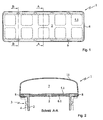
- the armrest 1 shown in the figures consists of a hard-elastic or plastically deformable support structure 2, which can be produced, for example, from a polypropylene (PP) or a PP compound by injection molding.
- the armrest can be solved via a locking connection 3 with a in FIG. 2 indicated center console 4 are connected.
- the support structure 2 is formed lattice-like, so that they basically has sufficient strength for use, but in an accidental lateral load, for example, the impact of a sitting next to the center console seat occupant, is elastically or plastically deformable.
- the forces acting on the seat occupant local forces can be significantly reduced by this training over a full-surface closed support structure.
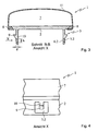
- the resulting in the lattice-like design of the support structure recesses 5.1 are, as in FIG. 2 shown sealed with a membranous, soft elastic component 6.1. It is therefore possible, without further action, to insert the sealed support structure 2 into a foaming tool and to cushion it on the support side for the arm of the seat occupant by foaming a foam pad 7, for example of a PUR foam.
- the foam pad 7 is laminated on the support side with a decor 11, for example made of leather, a plastic film or a textile fabric.
- a material for the soft elastic component is for example a polyolefinic thermoplastic elastomer (TPE-O) having a hardness of 60 to 80 Shore A into consideration.
- TPE-O polyolefinic thermoplastic elastomer
- This material can be combined well with a support structure made of PP, only slightly increases its rigidity and has sufficient strength to withstand the foaming pressure during foaming of the foam pad 7.
- a sealing bead 8 which surrounds the support structure laterally in its entirety, is also injection-molded from the same material, which seals the support structure 2 in the foaming tool and prevents the foam from passing.
- care must be taken to ensure that the expanding foam can be removed from the cavity to be displaced air.
- the support structure 2 is further provided with a number of U-shaped recesses 5.2, which form locking lugs 10 provided in the region of the locking connections 3 with latching hooks 9.
- the recesses 5.2 are also closed with a soft elastic component 6.2, which is preferably molded in one operation with the remaining soft components of the same material.
- the wall thickness d of the soft elastic component is dimensioned such that it is smaller than the width b of the recess 5.2 to reduce the deformation resistance.
- the wall thickness d is about half the width b, so that the flexibility of the tongue 10 is not unduly reduced by the connection of the soft elastic component.
Abstract
Description
Die Erfindung betrifft ein Ausstattungsteil für den Innenraum eines Kraftfahrzeugs, aus einer ersten, hartelastischen oder plastisch verformbaren Trägerstruktur und einer mit dieser einstückig verbundenen zweiten, weichelastischen Komponente, welche die mit Ausnehmungen versehene Trägerstruktur dichtend verschließt, sowie ein Verfahren zur Herstellung eines derartigen Bauteils, bei dem die mit Ausnehmungen versehene hartelastische oder plastisch verformbare Trägerstruktur bevorzugt durch Spritzgießen ausgeformt wird.The invention relates to a fitting for the interior of a motor vehicle, from a first, hard-elastic or plastically deformable support structure and integrally connected thereto second, soft elastic component, which closes the recess provided with carrier structure sealing, and a method for producing such a component in at in which the recess-provided hard-elastic or plastically deformable support structure is preferably formed by injection molding.
Aus der Offenlegungsschrift
Bei der Herstellung eines derartigen Bauteils wird in einer Spritzgießform zuerst das Innenteil in einer gegenüber der Sollkontur um die Wanddicke der Hartkomponente verkleinerten Kavität auf einen Formkern aufgeformt. Anschließend wird der Formkern mit dem aufgeformten weichen Innenteil in das Formnest einer vergrößerten Gießform eingesetzt. Bei geschlossenem Werkzeug kann nun der zwischen Innenteil und Formnest verbleibende Spalt mit dem harten Kunststoff ausgefüllt werden.In the production of such a component, the inner part is first molded onto a mandrel in an injection mold in a cavity which is reduced in size by the wall thickness of the hard component relative to the desired contour. Subsequently, the mandrel is used with the molded soft inner part in the mold cavity of an enlarged mold. When the tool is closed, the gap remaining between the inner part and the mold cavity can now be filled with the hard plastic.
Dieses Vorgehen hat grundsätzlich den Nachteil, dass ein erheblicher Werkstoffeinsatz der vergleichsweise teuren Weichkomponente erforderlich ist. Es eignet sich daher nur für Bauteile, bei denen die Innenschale zur Verbesserung der Haptik vollflächig mit einer weichen Wanne auszukleiden ist.This procedure basically has the disadvantage that a considerable use of material of the comparatively expensive soft component is required. It is therefore only suitable for components in which the inner shell to improve the feel of the entire surface is lined with a soft tub.
Im gleichen Dokument wird ein vorbekanntes Verfahren beschrieben, bei dem ein derartiges Ablagefach durch Spritzgießen der äußeren harten Wanne gefertigt wird. Nach dem Ausziehen des Formkerns werden ein anderer Formkern kleineren Querschnitts in das Wanneninnere eingeführt und der entstehende Spalt mit der Weichkomponente ausgefüllt. Dabei ist nach Auffassung des Anmelders unbedingt zu vermeiden, dass weiches Kunststoffmaterial in freigelegte Rastkonturen der Hartschale einläuft.In the same document a previously known method is described in which such a storage compartment is made by injection molding of the outer hard tub. After the mold core has been removed, another mold core of smaller cross-section is introduced into the interior of the bath, and the resulting gap is filled with the soft component. It should be avoided, in the applicant's opinion, that soft plastic material runs into exposed catch contours of the hard shell.
Der Erfindung liegt die Aufgabe zugrunde, ein gedichtetes Ausstattungsteil für den Innenraum eines Kraftfahrzeugs bereitzustellen, welches verformbare Trägerstrukturen mit einer ausreichenden Grundsteifigkeit besitzt, aber dennoch bei einem Unfall, beispielsweise einem seitlichen Aufprall, ein günstiges Verformungsverhalten aufweist. Ferner soll es sich mit einem relativ geringen Anteil an weichelastischer Werkstoffkomponente mittels eines einfachen und prozesssicheren Verfahrens fertigen lassen.The invention has for its object to provide a sealed fitting part for the interior of a motor vehicle, which has deformable support structures with a sufficient basic stiffness, but nevertheless has a favorable deformation behavior in an accident, such as a side impact. Furthermore, it should be able to be finished with a relatively small proportion of soft elastic material component by means of a simple and process-safe process.
Die Aufgabe wird erfindungsgemäß dadurch gelöst, dass die Ausnehmungen des Bauteils durch die weichelastische Komponente im Wesentlichen ausgefüllt und damit dichtend verschlossen sind.The object is achieved in that the recesses of the component are substantially filled by the soft elastic component and thus sealed.
Die hartelastische Trägerstruktur kann dabei nach einer bevorzugten Ausführungsform U-förmige Ausnehmungen aufweisen, die in die Trägerstruktur eingeformte Rastzungen ausbilden und beispielsweise zur lösbaren Befestigung des Bauteils in einem Gesamtsystem dienen. Dabei wird die örtliche Wanddicke der die Ausnehmung dichtend ausfüllenden weichelastischen Komponente vorzugsweise geringer, insbesondere um mindestens die Hälfte niedriger ist als die örtliche Breite der betreffenden Ausnehmung ausgebildet. Auf diese Weise ist die weichelastische Füllung der Ausnehmung ausreichend verformbar, so dass die zum Einfügen der Rastzungen erforderlichen Verwölbungen schadensfrei und unter geringem Kraftaufwand vorgenommen werden können.According to a preferred embodiment, the hard-elastic support structure may have U-shaped recesses which form latching tongues molded into the support structure and serve, for example, for the releasable fastening of the component in an overall system. In this case, the local wall thickness of the recess sealingly filling soft elastic component is preferably less, in particular by at least half is formed lower than the local width of the respective recess. In this way, the soft elastic filling of the recess is sufficiently deformable, so that the curvatures required for inserting the locking tongues can be made damage-free and with little effort.
Nach einer anderen bevorzugten Ausführungsform der Erfindung ist die hartelastische oder plastisch verformbare Trägerstruktur gitterartig ausgebildet, wobei die zwischen den Gitterelementen ausgebildeten flächigen Ausnehmungen durch die weichelastische Komponente im Wesentlichen ausgefüllt und damit dichtend verschlossen sind. Ein derartiges Bauteil weist zwar eine ausreichende Grundsteifigkeit auf, kann sich jedoch bei seitlichem Aufprall plastisch verformen, ohne dass eine unerwünscht hohe Verformungskraft aufzuwenden ist.According to another preferred embodiment of the invention, the hard-elastic or plastically deformable support structure is formed like a lattice, wherein the area between the grid elements formed recesses are substantially filled by the soft elastic component and thus sealed sealing. Although such a component has a sufficient basic rigidity, but can deform plastically in a side impact, without an undesirably high deformation force is expended.
Der dichtende Verschluß durch die weichelastische Komponente ermöglicht ferner das Aufbringen einer die hartelastische oder plastisch verformbare Trägerstruktur und den die Ausnehmungen dichtend ausfüllenden weichelastischen Anteil einseitig bedeckenden Schaumlage, insbesondere aus einem PUR-Schaum, ohne dass bei der Fertigung besondere Maßnahmen zum Verschluß der Ausnehmungen während des Schäumvorgangs vorzunehmen sind. In diesem speziellen Fall kann es jedoch angebracht sein, die Trägerstruktur wie im zitierten Stand der Technik innen- oder außenseitig zur Abdichtung ganz oder zumindest im Bereich der Ausnehmungen mit der weichelastischen Komponente zu überziehen. Nach einer weiteren Ausbildung der Erfindung kann dabei mit Vorteil vorgesehen werden, dass die Schaumlage an ihrem seitlichen, der Trägerstruktur zugewandten Anlage vollumfänglich von einem einstückig an die Trägerstruktur angeformten Dichtwulst aus weichelastischem Werkstoff umgeben ist. Der Dichtwulst dichtet die Trägerstruktur im Schäumwerkzeug seitlich ab, so dass der Schaum nicht aus der Werkzeugkavität austreten kann.The sealing closure by the soft elastic component further allows the application of a hard-elastic or plastically deformable support structure and the recesses sealingly filling soft elastic portion on one side covering foam layer, in particular of a polyurethane foam without special measures during production for closing the recesses during the Foaming process are to be made. In this special case, however, it may be appropriate to cover the support structure as in the cited prior art inside or outside to seal completely or at least in the region of the recesses with the soft elastic component. According to a further embodiment of the invention can be provided with advantage that the foam layer is fully surrounded on its lateral, the support structure facing system of a integrally formed on the support structure sealing bead of soft elastic material. The sealing bead seals the support structure laterally in the foaming tool so that the foam can not escape from the tool cavity.
Nach außen kann der Schaum zusätzlich mit einem flächigem Dekormaterial, insbesondere einer Kunststofffolie, einem Gewebe oder einem Leder kaschiert werden.To the outside, the foam can be additionally laminated with a flat decorative material, in particular a plastic film, a fabric or a leather.
Das erfindungsgemäße Verfahren zur Herstellung des Bauteils ist dadurch gekennzeichnet, dass die Ausnehmungen nachfolgend durch Einspritzen einer weichelastischen Komponente dichtend ausgefüllt werden.The inventive method for producing the component is characterized in that the recesses are subsequently filled by sealing a soft elastic component sealing.
Nach einer besonderen Weiterbildung des Verfahrens kann dabei zeitgleich mit dem Einspritzen der weichelastischen Komponente in die Ausnehmungen oder zeitversetzt zu diesem Vorgang ein bevorzugt umlaufender Dichtwulst aus weichelastischer Komponente an die Trägerstruktur angeformt werden. Nachfolgend kann die Trägerstruktur in ein Schäumwerkzeug eingelegt und zumindest einseitig mit einer Schaumlage versehen werden. In einem weiteren Verfahrensschritt kann vorgesehen werden, dass vor dem Schäumen ein flächiges Dekormaterial in das Schäumwerkzeug eingelegt und nachfolgend die Schaumlage in den Raum zwischen Dekormaterial und Trägerstruktur eingebracht wird. Alternativ kann auf die Schaumlage im Anschluß an den Schäumprozess ein flächiges Dekormaterial aufkaschiert, insbesondere aufgeklebt werden.According to a particular embodiment of the method, a preferably circumferential sealing bead made of soft elastic component can be molded onto the support structure simultaneously with the injection of the soft elastic component into the recesses or with a time delay to this process. Subsequently, the support structure can be inserted into a foaming tool and provided at least on one side with a foam layer. In a further method step, it can be provided that, before foaming, a sheetlike decorative material is inserted into the foaming tool and subsequently the foam layer is introduced into the space between the decorative material and the carrier structure. Alternatively, a sheet-like decorative material can be laminated on the foam layer following the foaming process, in particular adhesively bonded.
Die Figuren stellen beispielhaft und schematisch eine Ausführung der Erfindung dar.The figures illustrate by way of example and schematically an embodiment of the invention.
Es zeigen:
- Fig. 1
- eine erfindungsgemäß gestaltete Armauflage für eine Mittelkonsole in Aufsicht
- Fig. 2
- die Armauflage nach
Fig. 1 im Schnitt A-A - Fig. 3
- die Armauflage nach
Fig. 1 im Schnitt B-B - Fig. 4
- einen Ausschnitt einer seitlichen Ansicht auf die Armauflage nach
Fig. 3 aus Richtung X
- Fig. 1
- an inventively designed armrest for a center console in supervision
- Fig. 2
- the armrest after
Fig. 1 on average AA - Fig. 3
- the armrest after
Fig. 1 in section BB - Fig. 4
- a section of a side view of the armrest
Fig. 3 from direction X
Die in den Figuren dargestellte Armauflage 1 besteht aus einer hartelastischen oder plastisch verformbaren Trägerstruktur 2, die beispielsweise aus einem Polypropylen (PP) oder einem PP-Compound durch Spritzgießen herstellbar ist. Die Armauflage kann über eine Rastverbindung 3 lösbar mit einer in
Wie aus
Die bei der gitterartigen Ausbildung der Trägerstruktur entstehenden Ausnehmungen 5.1 sind, wie in
Als Werkstoff für die weichelastische Komponente kommt beispielsweise ein polyolefinisches thermoplastisches Elastomer (TPE-O) mit einer Härte von 60 bis 80 Shore A in Betracht. Dieses Material läßt sich gut mit einer aus PP gefertigten Trägerstruktur verbinden, erhöht dessen Steifigkeit nur geringfügig und weist eine ausreichende Festigkeit auf, um dem Schäumdruck beim Anschäumen des Schaumkissens 7 zu widerstehen.As a material for the soft elastic component is for example a polyolefinic thermoplastic elastomer (TPE-O) having a hardness of 60 to 80 Shore A into consideration. This material can be combined well with a support structure made of PP, only slightly increases its rigidity and has sufficient strength to withstand the foaming pressure during foaming of the
Gemeinsam mit der membranartigen weichelastischen Komponente 6.1 wird aus dem gleichen Werkstoff ferner ein die Trägerstruktur seitlich vollumfänglich umgebender Dichtwulst 8 angespritzt, der die Trägerstruktur 2 im Schäumwerkzeug abdichtet und einen Übertritt des Schaums verhindert. Selbstverständlich ist dabei Sorge zu tragen, dass die vom sich ausdehnenden Schaum aus der Kavität zu verdrängende Luft abgeführt werden kann.Together with the membrane-like soft-elastic component 6.1, a
Wie aus
Aus optischen Gründen sind die Ausnehmungen 5.2 ebenfalls mit einer weichelastischen Komponente 6.2 verschlossen, die bevorzugt in einem Arbeitsgang mit den übrigen Weichanteilen aus dem gleichen Werkstoff angespritzt wird. Die Wanddicke d der weichelastischen Komponente ist dabei zur Reduzierung des Verformungswiderstands so bemessen, dass sie geringer ist als die Breite b der Ausnehmung 5.2. Im Ausführungsbeispiel beträgt die Wanddicke d etwa die Hälfte der Breite b, so dass die Flexibilität der Zunge 10 durch die Anbindung der weichelastischen Komponente nicht unzulässig herabgesetzt wird.For optical reasons, the recesses 5.2 are also closed with a soft elastic component 6.2, which is preferably molded in one operation with the remaining soft components of the same material. The wall thickness d of the soft elastic component is dimensioned such that it is smaller than the width b of the recess 5.2 to reduce the deformation resistance. In the exemplary embodiment, the wall thickness d is about half the width b, so that the flexibility of the
- 11
- Armlehnearmrest
- 22
- Trägerstruktursupport structure
- 33
- Rastverbindunglocking connection
- 44
- Mittelkonsolecenter console
- 55
- Ausnehmungrecess
- 66
- weichelastische Komponentesoft elastic component
- 77
- Schaumkissenfoam cushion
- 88th
- Dichtwulstsealing bead
- 99
- Rasthakenlatch hook
- 1010
- Rastzungecatch tongue
- 1111
- Dekordecor
Claims (12)
- Equipment part for the interior of a motor vehicle, consisting of a first, hard-elastic or plastically deformable carrier structure (2) and of a second, soft-elastic component (6) which is connected in one piece to the latter and which sealingly closes the carrier structure provided with recesses (5), characterized in that the recesses (5) are essentially filled by the soft-elastic component (6) and are consequently sealingly closed.
- Equipment part according to Claim 1, characterized in that the hard-elastic carrier structure (2) preferably has U-shaped recesses (5.2) which form latching tongues (10) integrally formed into the carrier structure.
- Equipment part according to Claim 2, characterized in that the local wall thickness (d) of the soft-elastic component (6) sealingly filling the recess (5.2) is smaller than, in particular at most half as large as, the local width (b) of the respective recess.
- Equipment part according to one of the preceding claims, characterized in that the hard-elastic or plastically deformable carrier structure (2) is of grid-like design, the sheet-like recesses (5.1) formed between the grid elements being essentially filled by the soft-elastic component (6.1) and consequently being sealingly closed.
- Equipment part according to one of the preceding claims, characterized by a foam layer, particularly in the form of a foam cushion (7) consisting of a PUR foam, which covers on one side the hard-elastic or plastically deformable carrier structure (2) and the soft-elastic component sealing the recesses (5.1).
- Equipment part according to Claim 5, characterized in that the foam layer is preferably surrounded over the entire circumference by a sealing bead (8) consisting of soft-elastic material and integrally formed in one piece onto the carrier structure (2).
- Equipment part according to Claim 5 or 6, characterized in that the foam is coated with a sheet-like decoration (11), in particular a plastic film, a sheet-like textile structure or a leather.
- Method for producing an equipment part according to Claim 1, in which the hard-elastic or plastically deformable carrier structure (2) provided with recesses (5) is preferably formed by injection molding, characterized in that the recesses (5) are subsequently sealingly filled by the injection of a soft-elastic component (6).
- Method according to Claim 8, characterized in that, at the same time or offset in time, a preferably peripheral sealing bead (8) consisting of soft-elastic material is integrally formed onto the carrier structure (2).
- Method according to Claim 8 or 9, characterized in that the carrier structure (8) is subsequently introduced into a foaming die and is provided at least on one side with a foam layer, in particular a foam cushion (7).
- Method according to Claim 10, characterized in that a sheet-like decoration (11) is introduced into the foaming die and the foam layer is subsequently introduced into the space between the decoration and the carrier structure (2).
- Method according to Claim 10, characterized in that a sheet-like decoration (11) is subsequently coated, in particular glued, onto the foam layer.
Applications Claiming Priority (3)
| Application Number | Priority Date | Filing Date | Title |
|---|---|---|---|
| DE10211656 | 2002-03-15 | ||
| DE10211656A DE10211656C1 (en) | 2002-03-15 | 2002-03-15 | Interior fitting for a vehicle, e.g. an arm rest, has a carrier structure with hard elasticity bonded to a section of soft elasticity e.g. a foam cushion, where the bonding openings are wholly filled and sealed |
| PCT/EP2003/002695 WO2003078149A1 (en) | 2002-03-15 | 2003-03-14 | Deformable component, in particular fitting for a motor vehicle and method for producing the same |
Publications (2)
| Publication Number | Publication Date |
|---|---|
| EP1487632A1 EP1487632A1 (en) | 2004-12-22 |
| EP1487632B1 true EP1487632B1 (en) | 2010-08-18 |
Family
ID=7714124
Family Applications (1)
| Application Number | Title | Priority Date | Filing Date |
|---|---|---|---|
| EP03744364A Expired - Lifetime EP1487632B1 (en) | 2002-03-15 | 2003-03-14 | Deformable component, in particular fitting for a motor vehicle and method for producing the same |
Country Status (7)
| Country | Link |
|---|---|
| US (1) | US7357443B2 (en) |
| EP (1) | EP1487632B1 (en) |
| JP (1) | JP4785344B2 (en) |
| CN (1) | CN100515740C (en) |
| AT (1) | ATE477918T1 (en) |
| DE (2) | DE10211656C1 (en) |
| WO (1) | WO2003078149A1 (en) |
Families Citing this family (16)
| Publication number | Priority date | Publication date | Assignee | Title |
|---|---|---|---|---|
| US7556301B2 (en) | 2006-03-28 | 2009-07-07 | Ford Global Technologies, Llc | Dynamically deconstructable armrest for automotive vehicle |
| DE102011112164B4 (en) * | 2011-08-29 | 2018-05-17 | Faurecia Innenraum Systeme Gmbh | Method for producing a vehicle interior trim part and vehicle interior trim part |
| EP2790891B1 (en) | 2012-10-09 | 2016-10-26 | Reliant Worldwide Plastics, LLC | Thermoplastic injection molded element with integral thermoplastic positioning system for reinforced composite structures |
| DE102013100903A1 (en) | 2013-01-30 | 2014-07-31 | Dr. Ing. H.C. F. Porsche Aktiengesellschaft | Armrest for a door of a motor vehicle |
| DE102013103382A1 (en) * | 2013-04-04 | 2014-10-09 | Recaro Aircraft Seating Gmbh & Co. Kg | armrests device |
| US9394052B2 (en) | 2013-09-10 | 2016-07-19 | Reliant Worldwide Plastics, Llc | Tray table and method of manufacture |
| US9925897B2 (en) * | 2013-12-17 | 2018-03-27 | Ford Global Technologies, Llc | Door trim armrest substrate structure |
| US9254765B2 (en) * | 2013-12-17 | 2016-02-09 | Ford Global Technologies, Llc | Vehicle armrest with structural fabric substrate |
| WO2015168680A1 (en) | 2014-05-02 | 2015-11-05 | Reliant Worldwide Plastics, Llc | Method and system for homogenous thermoplastic seat back assembly |
| EP3154825A4 (en) * | 2014-06-16 | 2018-04-25 | Reliant Worldwide Plastics, LLC | Method and apparatus for composite thermoplastic arm rest assembly |
| US9643651B2 (en) | 2015-08-28 | 2017-05-09 | Honda Motor Co., Ltd. | Casting, hollow interconnecting member for connecting vehicular frame members, and vehicular frame assembly including hollow interconnecting member |
| WO2017070186A1 (en) | 2015-10-23 | 2017-04-27 | Reliant Worldwide Plastics, Llc | Method and apparatus for a homogeneous thermoplastic leg support |
| WO2017079088A1 (en) | 2015-11-04 | 2017-05-11 | Reliant Worldwide Plastics, Llc | Method and apparatus for a thermoplastic homogeneous failure module |
| US9994137B2 (en) | 2016-02-16 | 2018-06-12 | Ford Global Technologies, Llc | Deformable armrest having a patterned array of channels |
| DE102018131247A1 (en) * | 2018-12-06 | 2020-06-10 | Metak GmbH & Co. KG | Armrest for chairs and chairs with such an armrest |
| DE102018131754A1 (en) * | 2018-12-11 | 2020-06-18 | Bayerische Motoren Werke Aktiengesellschaft | Process for the production of vehicle spare parts |
Family Cites Families (14)
| Publication number | Priority date | Publication date | Assignee | Title |
|---|---|---|---|---|
| DE2434768A1 (en) | 1974-07-19 | 1976-02-05 | Gruenzweig Hartmann Glasfaser | Noise-damping thermally non-insulating, panel - comprises a perforated carrier plate with foam-filled apertures |
| JPS57120421A (en) * | 1981-01-16 | 1982-07-27 | Tokai Kasei Kogyo Kk | Manufacture of foamed product lined with core material |
| BR8407275A (en) * | 1984-02-03 | 1986-01-21 | Duret M & Fils | PROCESS FOR THE MANUFACTURING OF A SEATING ELEMENT THROUGH THE FRAMING OF A FRAME ON A GARAGE AND SEATING ELEMENT OBTAINED BY THE PROCESS REFERRED TO |
| US5244251A (en) * | 1990-01-05 | 1993-09-14 | Ilan Bourla | Pneumatic seat for bicycle and method of manufacture |
| JP2978355B2 (en) * | 1993-02-26 | 1999-11-15 | 株式会社イノアックコーポレーション | Shock absorbing structure for vehicle door |
| US5348369A (en) * | 1993-03-01 | 1994-09-20 | Yu Tsai Yun | Saddle for a bicycle |
| JP3320213B2 (en) * | 1994-08-25 | 2002-09-03 | 三菱自動車工業株式会社 | Impact energy absorbing structure in the vehicle interior |
| JP3604183B2 (en) * | 1994-11-14 | 2004-12-22 | 株式会社イノアックコーポレーション | Interior parts for vehicles |
| DE19752786A1 (en) * | 1996-12-19 | 1998-06-25 | Sarnatech Paulmann & Crone | Inbuilt glove box compartment, having soft interior surface and harder exterior |
| JPH11139232A (en) * | 1997-11-07 | 1999-05-25 | Kasai Kogyo Co Ltd | Arm rest structure for automobile |
| US6142563A (en) * | 1998-10-09 | 2000-11-07 | Joalto Design | Vehicle seat with energy absorbing deformable structural material |
| JP4263808B2 (en) * | 1999-05-31 | 2009-05-13 | 株式会社岡村製作所 | Chair armrest equipment |
| US6343839B1 (en) * | 1999-12-17 | 2002-02-05 | Steelcase Development Corporation | Flexible armrest construction |
| US7201434B1 (en) * | 2005-11-04 | 2007-04-10 | Cadence Innovation Llc | Energy-absorbing bolster for an automotive instrument panel assembly |
-
2002
- 2002-03-15 DE DE10211656A patent/DE10211656C1/en not_active Expired - Fee Related
-
2003
- 2003-03-14 DE DE50313000T patent/DE50313000D1/en not_active Expired - Lifetime
- 2003-03-14 US US10/507,981 patent/US7357443B2/en not_active Expired - Fee Related
- 2003-03-14 WO PCT/EP2003/002695 patent/WO2003078149A1/en active Application Filing
- 2003-03-14 JP JP2003576181A patent/JP4785344B2/en not_active Expired - Fee Related
- 2003-03-14 AT AT03744364T patent/ATE477918T1/en active
- 2003-03-14 EP EP03744364A patent/EP1487632B1/en not_active Expired - Lifetime
- 2003-03-14 CN CNB038061147A patent/CN100515740C/en not_active Expired - Fee Related
Also Published As
| Publication number | Publication date |
|---|---|
| ATE477918T1 (en) | 2010-09-15 |
| JP2005527400A (en) | 2005-09-15 |
| WO2003078149A1 (en) | 2003-09-25 |
| DE50313000D1 (en) | 2010-09-30 |
| CN1642720A (en) | 2005-07-20 |
| JP4785344B2 (en) | 2011-10-05 |
| US7357443B2 (en) | 2008-04-15 |
| DE10211656C1 (en) | 2003-07-17 |
| EP1487632A1 (en) | 2004-12-22 |
| US20050168003A1 (en) | 2005-08-04 |
| CN100515740C (en) | 2009-07-22 |
Similar Documents
| Publication | Publication Date | Title |
|---|---|---|
| EP1487632B1 (en) | Deformable component, in particular fitting for a motor vehicle and method for producing the same | |
| DE102004021222B4 (en) | Hard or soft composite panel with foam layer | |
| DE602005000107T2 (en) | Cladding element, in particular for a vehicle interior, and manufacturing method thereof | |
| DE102006001663B4 (en) | United, padded interior trim panel for a vehicle | |
| DE2110382A1 (en) | Vehicle seat, especially for tractors | |
| EP2953815B1 (en) | Headrest for a vehicle and a method of producing the same | |
| DE3823584A1 (en) | METHOD FOR PRODUCING A UPHOLSTERY PART | |
| DE3712882C2 (en) | ||
| DE102015201237A1 (en) | Lightweight seat for vehicles | |
| DE102019117112A1 (en) | HYBRID-DOOR MODULE | |
| DE102010040021A1 (en) | Door interior trim for vehicle doors | |
| EP2335900B1 (en) | Method for producing a moulded interior panel | |
| DE102007053009B4 (en) | Fastening arrangement for a seat cover, in particular a vehicle seat, and a mounting method | |
| DE3300509A1 (en) | Sealing profile of elastomeric material, especially for motor vehicle bodies, and process for the manufacture thereof | |
| DE4024274A1 (en) | Recyclable polypropylene upholstery for vehicles - has centre layer foamed in die between outer layers | |
| DE3816167C1 (en) | ||
| DE2726141A1 (en) | Foam pad for head rest for use in a vehicle - has additional very much softer, foam bolster firmly moulded onto it | |
| DE19700759C1 (en) | Profile for side airbag of motor vehicle | |
| DE102010019927A1 (en) | Padding part for padding support structure of back of seat i.e. motor car seat, in motor car, has male insert comprising mold member and firmly connected with edge such that edge is fixed and actuated at air bag module housing member | |
| DE3939301C2 (en) | ||
| DE102008039607A1 (en) | Cover part for interior of vehicle, particularly passenger car, comprises carrier, external layer and intermediate carrier, where foam layer is arranged on external layer | |
| DE10211631B4 (en) | Equipment part, in particular for interior equipment in vehicles | |
| DE102019204206A1 (en) | Molding tool and method for producing a trim component from an expanded plastic granulate for visible attachment in an interior of a vehicle | |
| DE3425277A1 (en) | PLASTIC ELASTIC SUPPORT FOR ONE SEAT | |
| DE102020124414A1 (en) | Door lining with different add-on parts |
Legal Events
| Date | Code | Title | Description |
|---|---|---|---|
| PUAI | Public reference made under article 153(3) epc to a published international application that has entered the european phase |
Free format text: ORIGINAL CODE: 0009012 |
|
| 17P | Request for examination filed |
Effective date: 20041015 |
|
| AK | Designated contracting states |
Kind code of ref document: A1 Designated state(s): AT BE BG CH CY CZ DE DK EE ES FI FR GB GR HU IE IT LI LU MC NL PT RO SE SI SK TR |
|
| 17Q | First examination report despatched |
Effective date: 20070529 |
|
| GRAP | Despatch of communication of intention to grant a patent |
Free format text: ORIGINAL CODE: EPIDOSNIGR1 |
|
| GRAS | Grant fee paid |
Free format text: ORIGINAL CODE: EPIDOSNIGR3 |
|
| GRAA | (expected) grant |
Free format text: ORIGINAL CODE: 0009210 |
|
| AK | Designated contracting states |
Kind code of ref document: B1 Designated state(s): AT BE BG CH CY CZ DE DK EE ES FI FR GB GR HU IE IT LI LU MC NL PT RO SE SI SK TR |
|
| REG | Reference to a national code |
Ref country code: GB Ref legal event code: FG4D Free format text: NOT ENGLISH |
|
| REG | Reference to a national code |
Ref country code: CH Ref legal event code: EP |
|
| REG | Reference to a national code |
Ref country code: IE Ref legal event code: FG4D Free format text: LANGUAGE OF EP DOCUMENT: GERMAN |
|
| REF | Corresponds to: |
Ref document number: 50313000 Country of ref document: DE Date of ref document: 20100930 Kind code of ref document: P |
|
| REG | Reference to a national code |
Ref country code: NL Ref legal event code: VDEP Effective date: 20100818 |
|
| PG25 | Lapsed in a contracting state [announced via postgrant information from national office to epo] |
Ref country code: FI Free format text: LAPSE BECAUSE OF FAILURE TO SUBMIT A TRANSLATION OF THE DESCRIPTION OR TO PAY THE FEE WITHIN THE PRESCRIBED TIME-LIMIT Effective date: 20100818 |
|
| REG | Reference to a national code |
Ref country code: SK Ref legal event code: T3 Ref document number: E 8190 Country of ref document: SK |
|
| PG25 | Lapsed in a contracting state [announced via postgrant information from national office to epo] |
Ref country code: SI Free format text: LAPSE BECAUSE OF FAILURE TO SUBMIT A TRANSLATION OF THE DESCRIPTION OR TO PAY THE FEE WITHIN THE PRESCRIBED TIME-LIMIT Effective date: 20100818 Ref country code: PT Free format text: LAPSE BECAUSE OF FAILURE TO SUBMIT A TRANSLATION OF THE DESCRIPTION OR TO PAY THE FEE WITHIN THE PRESCRIBED TIME-LIMIT Effective date: 20101220 Ref country code: CY Free format text: LAPSE BECAUSE OF FAILURE TO SUBMIT A TRANSLATION OF THE DESCRIPTION OR TO PAY THE FEE WITHIN THE PRESCRIBED TIME-LIMIT Effective date: 20100818 Ref country code: BG Free format text: LAPSE BECAUSE OF FAILURE TO SUBMIT A TRANSLATION OF THE DESCRIPTION OR TO PAY THE FEE WITHIN THE PRESCRIBED TIME-LIMIT Effective date: 20101118 |
|
| REG | Reference to a national code |
Ref country code: IE Ref legal event code: FD4D |
|
| REG | Reference to a national code |
Ref country code: HU Ref legal event code: AG4A Ref document number: E009276 Country of ref document: HU |
|
| PG25 | Lapsed in a contracting state [announced via postgrant information from national office to epo] |
Ref country code: NL Free format text: LAPSE BECAUSE OF FAILURE TO SUBMIT A TRANSLATION OF THE DESCRIPTION OR TO PAY THE FEE WITHIN THE PRESCRIBED TIME-LIMIT Effective date: 20100818 Ref country code: GR Free format text: LAPSE BECAUSE OF FAILURE TO SUBMIT A TRANSLATION OF THE DESCRIPTION OR TO PAY THE FEE WITHIN THE PRESCRIBED TIME-LIMIT Effective date: 20101119 Ref country code: SE Free format text: LAPSE BECAUSE OF FAILURE TO SUBMIT A TRANSLATION OF THE DESCRIPTION OR TO PAY THE FEE WITHIN THE PRESCRIBED TIME-LIMIT Effective date: 20100818 |
|
| PG25 | Lapsed in a contracting state [announced via postgrant information from national office to epo] |
Ref country code: IE Free format text: LAPSE BECAUSE OF FAILURE TO SUBMIT A TRANSLATION OF THE DESCRIPTION OR TO PAY THE FEE WITHIN THE PRESCRIBED TIME-LIMIT Effective date: 20100818 Ref country code: DK Free format text: LAPSE BECAUSE OF FAILURE TO SUBMIT A TRANSLATION OF THE DESCRIPTION OR TO PAY THE FEE WITHIN THE PRESCRIBED TIME-LIMIT Effective date: 20100818 |
|
| PG25 | Lapsed in a contracting state [announced via postgrant information from national office to epo] |
Ref country code: EE Free format text: LAPSE BECAUSE OF FAILURE TO SUBMIT A TRANSLATION OF THE DESCRIPTION OR TO PAY THE FEE WITHIN THE PRESCRIBED TIME-LIMIT Effective date: 20100818 Ref country code: IT Free format text: LAPSE BECAUSE OF FAILURE TO SUBMIT A TRANSLATION OF THE DESCRIPTION OR TO PAY THE FEE WITHIN THE PRESCRIBED TIME-LIMIT Effective date: 20100818 Ref country code: RO Free format text: LAPSE BECAUSE OF FAILURE TO SUBMIT A TRANSLATION OF THE DESCRIPTION OR TO PAY THE FEE WITHIN THE PRESCRIBED TIME-LIMIT Effective date: 20100818 |
|
| PLBE | No opposition filed within time limit |
Free format text: ORIGINAL CODE: 0009261 |
|
| STAA | Information on the status of an ep patent application or granted ep patent |
Free format text: STATUS: NO OPPOSITION FILED WITHIN TIME LIMIT |
|
| PG25 | Lapsed in a contracting state [announced via postgrant information from national office to epo] |
Ref country code: ES Free format text: LAPSE BECAUSE OF FAILURE TO SUBMIT A TRANSLATION OF THE DESCRIPTION OR TO PAY THE FEE WITHIN THE PRESCRIBED TIME-LIMIT Effective date: 20101129 |
|
| 26N | No opposition filed |
Effective date: 20110519 |
|
| REG | Reference to a national code |
Ref country code: DE Ref legal event code: R097 Ref document number: 50313000 Country of ref document: DE Effective date: 20110519 |
|
| BERE | Be: lapsed |
Owner name: JOHNSON CONTROLS INTERIORS G.M.B.H. & CO. KG Effective date: 20110331 |
|
| PG25 | Lapsed in a contracting state [announced via postgrant information from national office to epo] |
Ref country code: MC Free format text: LAPSE BECAUSE OF NON-PAYMENT OF DUE FEES Effective date: 20110331 |
|
| REG | Reference to a national code |
Ref country code: CH Ref legal event code: PL |
|
| GBPC | Gb: european patent ceased through non-payment of renewal fee |
Effective date: 20110314 |
|
| PG25 | Lapsed in a contracting state [announced via postgrant information from national office to epo] |
Ref country code: BE Free format text: LAPSE BECAUSE OF NON-PAYMENT OF DUE FEES Effective date: 20110331 |
|
| PG25 | Lapsed in a contracting state [announced via postgrant information from national office to epo] |
Ref country code: CH Free format text: LAPSE BECAUSE OF NON-PAYMENT OF DUE FEES Effective date: 20110331 Ref country code: LI Free format text: LAPSE BECAUSE OF NON-PAYMENT OF DUE FEES Effective date: 20110331 |
|
| PG25 | Lapsed in a contracting state [announced via postgrant information from national office to epo] |
Ref country code: GB Free format text: LAPSE BECAUSE OF NON-PAYMENT OF DUE FEES Effective date: 20110314 |
|
| REG | Reference to a national code |
Ref country code: AT Ref legal event code: MM01 Ref document number: 477918 Country of ref document: AT Kind code of ref document: T Effective date: 20110314 |
|
| PG25 | Lapsed in a contracting state [announced via postgrant information from national office to epo] |
Ref country code: AT Free format text: LAPSE BECAUSE OF NON-PAYMENT OF DUE FEES Effective date: 20110314 |
|
| PG25 | Lapsed in a contracting state [announced via postgrant information from national office to epo] |
Ref country code: LU Free format text: LAPSE BECAUSE OF NON-PAYMENT OF DUE FEES Effective date: 20110314 |
|
| PG25 | Lapsed in a contracting state [announced via postgrant information from national office to epo] |
Ref country code: TR Free format text: LAPSE BECAUSE OF FAILURE TO SUBMIT A TRANSLATION OF THE DESCRIPTION OR TO PAY THE FEE WITHIN THE PRESCRIBED TIME-LIMIT Effective date: 20100818 |
|
| REG | Reference to a national code |
Ref country code: FR Ref legal event code: PLFP Year of fee payment: 13 |
|
| PGFP | Annual fee paid to national office [announced via postgrant information from national office to epo] |
Ref country code: CZ Payment date: 20150225 Year of fee payment: 13 Ref country code: SK Payment date: 20150313 Year of fee payment: 13 Ref country code: HU Payment date: 20150319 Year of fee payment: 13 |
|
| PGFP | Annual fee paid to national office [announced via postgrant information from national office to epo] |
Ref country code: FR Payment date: 20150319 Year of fee payment: 13 |
|
| PG25 | Lapsed in a contracting state [announced via postgrant information from national office to epo] |
Ref country code: CZ Free format text: LAPSE BECAUSE OF NON-PAYMENT OF DUE FEES Effective date: 20160314 |
|
| REG | Reference to a national code |
Ref country code: SK Ref legal event code: MM4A Ref document number: E 8190 Country of ref document: SK Effective date: 20160314 |
|
| REG | Reference to a national code |
Ref country code: FR Ref legal event code: ST Effective date: 20161130 |
|
| PG25 | Lapsed in a contracting state [announced via postgrant information from national office to epo] |
Ref country code: HU Free format text: LAPSE BECAUSE OF NON-PAYMENT OF DUE FEES Effective date: 20160315 Ref country code: FR Free format text: LAPSE BECAUSE OF NON-PAYMENT OF DUE FEES Effective date: 20160331 Ref country code: SK Free format text: LAPSE BECAUSE OF NON-PAYMENT OF DUE FEES Effective date: 20160314 |
|
| PGFP | Annual fee paid to national office [announced via postgrant information from national office to epo] |
Ref country code: DE Payment date: 20170307 Year of fee payment: 15 |
|
| REG | Reference to a national code |
Ref country code: DE Ref legal event code: R119 Ref document number: 50313000 Country of ref document: DE |
|
| PG25 | Lapsed in a contracting state [announced via postgrant information from national office to epo] |
Ref country code: DE Free format text: LAPSE BECAUSE OF NON-PAYMENT OF DUE FEES Effective date: 20181002 |