EP1487241B1 - Kochgerät mit einem Gewichtmessgerät versehen - Google Patents
Kochgerät mit einem Gewichtmessgerät versehen Download PDFInfo
- Publication number
- EP1487241B1 EP1487241B1 EP04250413A EP04250413A EP1487241B1 EP 1487241 B1 EP1487241 B1 EP 1487241B1 EP 04250413 A EP04250413 A EP 04250413A EP 04250413 A EP04250413 A EP 04250413A EP 1487241 B1 EP1487241 B1 EP 1487241B1
- Authority
- EP
- European Patent Office
- Prior art keywords
- lever
- cooking
- cooking cavity
- cooking apparatus
- sensor housing
- Prior art date
- Legal status (The legal status is an assumption and is not a legal conclusion. Google has not performed a legal analysis and makes no representation as to the accuracy of the status listed.)
- Expired - Lifetime
Links
Images




Classifications
-
- F—MECHANICAL ENGINEERING; LIGHTING; HEATING; WEAPONS; BLASTING
- F24—HEATING; RANGES; VENTILATING
- F24C—DOMESTIC STOVES OR RANGES ; DETAILS OF DOMESTIC STOVES OR RANGES, OF GENERAL APPLICATION
- F24C7/00—Stoves or ranges heated by electric energy
- F24C7/02—Stoves or ranges heated by electric energy using microwaves
-
- H—ELECTRICITY
- H05—ELECTRIC TECHNIQUES NOT OTHERWISE PROVIDED FOR
- H05B—ELECTRIC HEATING; ELECTRIC LIGHT SOURCES NOT OTHERWISE PROVIDED FOR; CIRCUIT ARRANGEMENTS FOR ELECTRIC LIGHT SOURCES, IN GENERAL
- H05B6/00—Heating by electric, magnetic or electromagnetic fields
- H05B6/64—Heating using microwaves
- H05B6/6447—Method of operation or details of the microwave heating apparatus related to the use of detectors or sensors
- H05B6/6464—Method of operation or details of the microwave heating apparatus related to the use of detectors or sensors using weight sensors
-
- H—ELECTRICITY
- H05—ELECTRIC TECHNIQUES NOT OTHERWISE PROVIDED FOR
- H05B—ELECTRIC HEATING; ELECTRIC LIGHT SOURCES NOT OTHERWISE PROVIDED FOR; CIRCUIT ARRANGEMENTS FOR ELECTRIC LIGHT SOURCES, IN GENERAL
- H05B6/00—Heating by electric, magnetic or electromagnetic fields
- H05B6/64—Heating using microwaves
- H05B6/6408—Supports or covers specially adapted for use in microwave heating apparatus
- H05B6/6411—Supports or covers specially adapted for use in microwave heating apparatus the supports being rotated
Definitions
- the present invention relates to a cooking apparatus equipped with a weight measuring device and, more particularly, to a mounting structure of a weight sensor of a cooking apparatus that accurately measures a weight of food, and determines an appropriate cooking time using the measured weight of the food.
- an automatic cooking apparatus such as a gas oven, an electrical oven or a microwave oven
- food is automatically cooked according to a control method provided to the apparatus.
- Efficient use of the automatic cooking apparatus requires entry of information regarding the food, such as the kind of food or the amount of food, into the cooking apparatus in order to automatically cook the food with an appropriate amount of heating over an appropriate cooking time.
- the information regarding the food is provided by a user through an input unit of the automatic cooking apparatus.
- the user needs to use a separate weight measuring device to accurately measure the amount of food that requires cooking. If the user roughly estimates the amount of food and enters the roughly estimated amount of food into the automatic cooking apparatus that is not equipped with the separate weight measuring device, a discrepancy between the actual amount of food and the entered amount of food may occur resulting in an error. Due to the error, a control unit of the automatic cooking apparatus may not determine the appropriate cooking time and the appropriate amount of heating required to cook the food, thus, resulting in a reduced cooking quality.
- EP 0 608 797 discloses a cooking apparatus where the cooking apparatus is provided with a weighing device comprising a plate having a vertically movable shaft, and a fluid-containing bladder or a fluid-containing piston and cylinder assembly, and a pressure sensor for sensing the weight of a food product to be cooked in the oven.
- the present invention provides a cooking apparatus comprising a cooking cavity provided with a lever passing hole in an outer bottom surface of the cooking cavity, a rotatable tray located inside the cooking cavity to hold food, a plurality of rollers brought into rolling contact with the tray and a bottom surface of the cooking cavity to rotate with the tray when the tray is rotated a weight sensor disposed under the cooking cavity, and a lever; characterised in that the lever extends from the weight sensor and to lever passing hole to allow a first end of the lever to be pushed by food placed in the cooking cavity and transmit pressure to the weight sensor through a lever action; and wherein the lever further extends from the weight sensor to a track of the rollers and is arranged to transmit pressure applied by the rollers to the weight sensor through a lever action.
- FIG. 1 is a perspective view of a microwave oven, according to an embodiment of the present invention.
- a tray 110 is provided to allow food to be laid thereon and to be rotated.
- a tray motor (not shown) is disposed under the cooking cavity 102 to rotate the tray 110.
- the tray motor is mechanically connected to the tray 110 via a rotating shaft 104a, and is rotated together with the tray 110.
- a ring-shaped roller supporting member 108 is disposed on a bottom 104 of the cooking cavity 102.
- Rollers 108a are mounted on the roller supporting member 108 to be rotatable.
- the tray 110 is put on the rollers 108a, and is smoothly rotated together with the rotating shaft 104a on the bottom 104 of the cooking cavity 102 without a tilt or movement using the roller supporting member 108 and the rollers 108a.
- a first end 120 of a lever (see Figure 5) to transmit pressure to a weight sensor (see Figure 2) is protruded through a track along which the rollers 108a move on the bottom 104 of the cooking cavity 102.
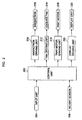
- FIG. 2 is a block diagram to show a control system of the microwave oven 100 of Figure 1 according to an embodiment of the present invention.
- a control unit 202 that controls an overall operation of the microwave oven 100 is connected at input terminals thereof to an input unit 204 and a weight sensor 206.
- the input unit 204 is provided with a cooking mode setting button (not shown) and numeral buttons (not shown) to allow a user to input cooking conditions.
- the control unit 202 is connected at output terminals thereof to a magnetron driving unit 208, a fan driving unit 212, a tray motor driving unit 216, and a display driving unit 220.
- the magnetron driving unit 208 drives a magnetron 210 to generate electromagnetic waves.
- the fan driving unit 212 drives a cooling fan 214 to cool various kinds of electric elements provided to a machine room (not shown).
- the tray motor driving unit 216 drives a tray motor 218 to rotate the tray 110 in the cooking cavity 102.
- the display driving unit 220 drives a display unit 222 to display help information required for cooking, cooking information, or currently set values.
- FIG 3 is a perspective view to show a mounting structure of a weight measuring device provided to the microwave oven 100 of Figure 1, according to an embodiment of the present invention.
- the weight sensor (not shown) accommodated in a sensor housing 304 is pushed onto an outer bottom surface 104b of the cooking cavity 102, that is, an outer surface of the bottom 104 of the cooking cavity 102, via a lever 306.
- the sensor housing 304 includes a lever fastening unit 304a.
- the lever fastening unit 304a is fastened by a fastening member 310 to allow rotation of the lever 306.
- a bracket 302 is fitted onto sides of the sensor housing 304 through an opening formed in a side of the bracket 302, and fastened by fastening members 308 to secure the sensor housing 304 to the outer bottom surface 104b of the cooking cavity.
- the bracket 302 is also attached to the outer bottom surface 104b of the cooking cavity 102 by welding, bonding, or other suitable securing technique.
- Figure 4 is an exploded perspective view to show the weight measuring device provided to the microwave oven, shown in Figure 3, according to an embodiment of the present invention.
- two positioning elements 416 are formed to indicate a mounting position of the sensor housing 304, and a lever passing hole 414 is formed to allow protrusion of the end 120 of the lever 306 into an inside of the cooking cavity 102.
- the lever passing hole 414 is formed on the outer bottom surface 104b of the cooking cavity 102 on the track of the rollers 108a.
- the positioning elements 416 are used to determine accurate relative positions of the lever passing hole 414 and the sensor housing 304.
- the relative positions refer to positions, which allow a first end 120 of the lever 306 to be passed through the lever passing hole 414, and a second end 420 of the lever 306 to be inserted into the sensor housing 304 when the sensor housing 304 is disposed to correspond to positions of the positioning elements 416 and the lever 306 is connected to the sensor housing 304.
- the positioning elements 416 constitute a pair. Accordingly, because the positions of the positioning elements 416 and a position of the lever passing hole 414 form a triangle, accurate positions and directions of the sensor housing 304 and the lever 306 are established.
- the positioning elements 416 may be formed by punching holes in the bottom 104 of the cooking cavity 102 or by forming grooves on the outer bottom surface 104b of the cooking cavity 102.
- the positioning elements 416 that determine the mounting position of the sensor housing 304 are spaced from the lever passing hole 414 by a predetermined distance. Since the sensor housing 304 and the lever passing hole 414 are spaced from each other, the weight sensor accommodated in the sensor housing 304 is protected from contamination even when moisture or the dregs separated from food in the cooking cavity 102 during cooking falls through the lever passing hole 414 to a space under the cooking cavity 102.
- the sensor housing 304 is used to accommodate the weight sensor therein.
- An opening is formed on an upper portion of the sensor housing 304 to accommodate the weight sensor in the sensor housing 304 through the opening.
- the weight sensor 502, accommodated through the opening is electrically connected to a separate control unit (not shown) to allow exchange of communication between the weight sensor 502 and the control unit.
- the sensor housing 304 is disposed on the outer bottom surface 104b of the cooking cavity 102 with the upper portion of the sensor housing 304 having the opening being brought into contact with the outer bottom surface 104b of the cooking cavity 102.
- a lever receiving hole 418 is formed on a portion of the sensor housing 304 opposite to the opening formed to accommodate the weight sensor 502.
- the second end 420 of the lever 306 is inserted into the lever receiving hole 418 and brought into contact with the weight sensor 502 accommodated in the sensor hosing 304.
- Two wing portions 410 are positioned at both sides of the sensor housing 304, respectively.
- Two protrusions (not shown), to be inserted into the positioning elements 416, are formed on the wing portions 410 that are brought into contact with the outer bottom surface 104b of the cooking cavity 102, respectively.
- Two fastening grooves 402 are formed on surfaces of the wing portions 410 opposite to surfaces of the wing portions 410 brought into contact with the outer bottom surface 104b of the cooking cavity 102, to allow portions of the fastening members 308 to be inserted therein. Spacing between the protrusions is the same as that of the spacing between the positioning elements 416 that are formed on the outer bottom surface 104b of the cooking cavity 102.
- the lever fastening unit 304a is integrated with the sensor housing 304.
- the lever 306 is fastened to the lever fastening unit 304a to be rotated by aligning fastening holes 406 of the lever fastening unit 304a with a fastening hole 408 of the lever 306 and then inserting the fastening member 310 into the fastening holes 406 and 408.
- a portion of the level fastening unit 304a into which the fastening member 310 is inserted acts as a fulcrum of the lever 306.
- the lever 306 is shaped similar to a rod.
- the first end 120 of the lever 306 is inserted through the lever passing hole 414 on the outer bottom surface 104b of the cooking cavity 102, and then protruded to the inside of the cooking cavity 102.
- the first end 120 of the lever 306 protruded to the inside of the cooking cavity 102 is pushed by the rollers 108a in the cooking cavity 102 so that a lever action occurs through the lever 306.
- the first end 120 of the lever 306 functions as a point of application of force, that is, a point where force is applied.
- the second end 420 of the lever 306 functions as a point of application of the lever action that is performed when the first end 120 of the lever 306 is pushed upon by the rollers 108a, that is, a point to where the force is transmitted.
- the second end 420 of the lever 306 pushes the weight sensor accommodated in the sensor housing 304 through the lever action.
- the bracket 302 is used to secure the sensor housing 304 to the outer bottom surface 104a of the cooking cavity 102, and is provided with a space formed by openings in one side portion and an upper portion of the bracket 302 so that the wing portions 410 of the sensor housing 304 are inserted thereinto and, therefore, brought into contact with the outer bottom surface 104b of the cooking cavity 102. Additionally, when the sensor housing 304 is secured by the bracket 302, the opening is formed on a lower portion of the bracket 302 so that the lever receiving hole 418 of the lever housing 304 and the lever fastening unit 304a are exposed below the bracket 302. That is, the bracket 302 has a "U" shape when viewed from below.
- Two fastening holes 404 are formed on a lower portion of the bracket 302.
- the fastening members 308 are inserted into the fastening holes 404 and push the fastening grooves 402 of the sensor housing 304 inserted through the side opening of the bracket 302.
- the weight sensor is accommodated in the sensor housing 304.
- the protrusions formed on the wing portions 410 of the sensor housing 304 are inserted to correspond to the positioning elements 416 of the outer bottom surface 104b of the cooking cavity 102 to allow the mounting position of the sensor housing 304 to be accurately determined.
- the bracket 302 is secured onto the sides of the sensor housing 304, and then the bracket 302 and the sensor housing 304 are fastened to each other by the fastening members 308.
- the bracket 302 is secured to a portion of the outer bottom surface 104b of the cooking cavity 102 by welding or bonding.
- the protrusions formed on the wing portions 410 of the sensor housing 304 are formed to have sizes so that the through holes are completely closed to prevent microwaves from leaking out of the microwave oven.
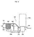
- Figure 5 is a side sectional view of the weight measuring device of the microwave oven shown in Figure 3, according to an embodiment of the present invention.
- the first end 120 of the lever 306 is pushed by the rollers 108a in the cooking cavity 102
- the second end 420 of the lever 306 pushes the weight sensor 502 accommodated in the sensor housing 304 through the lever action.
- the control unit 202 shown in Figure 2 detects an amount of pressure exerted on the weight sensor 502 by the lever 306, and determines a weight of an object laid on the tray 110.
- Figure 6 is another side sectional view of the weight measuring device of the microwave oven shown in Figure 3, according to another embodiment of the present invention.
- the protrusions 602 formed on the wing portions 410 of the sensor housing 304 are inserted into the positioning elements 416 having through hole shapes that are formed on the outer bottom surface 104b of the cooking cavity 102, and, thereby, the accurate mounting position of the sensor housing 304 is determined.
- an embodiment of the present invention provides a cooking apparatus, in which the mounting structure of the weight sensor to accurately and automatically measure a weight of food is improved, thereby preventing the weight sensor from being contaminated by the food.
Landscapes
- Physics & Mathematics (AREA)
- Electromagnetism (AREA)
- Engineering & Computer Science (AREA)
- Chemical & Material Sciences (AREA)
- Combustion & Propulsion (AREA)
- Mechanical Engineering (AREA)
- General Engineering & Computer Science (AREA)
- Electric Ovens (AREA)
Claims (31)
- Kochgerät (100) mit:einem Garraum (102), der mit einem Hebeldurchtrittsloch (414) auf einer äußeren unteren Oberfläche (104b) des Garraumes (102) versehen ist;einem drehbaren Tablett (110), das in dem Garraum (102) angeordnet ist, um Nahrungsmittel zu tragen;einer Mehrzahl an Rollen (108a), die mit dem Tablett (110) und einer unteren Oberfläche des Garraumes (102) in rollenden Kontakt gebracht ist, um sich mit dem Tablett (110) zu drehen, wenn das Tablett (110) gedreht wird;einem Gewichtssensor (206, 502), der unter dem Garraum (102) angeordnet ist; undeinem Hebel (306);dadurch gekennzeichnet,dass sich der Hebel von dem Gewichtssensor (206, 502) zu dem Hebeldurchtrittsloch (414) erstreckt, um es einem ersten Ende des Hebels zu ermöglichen, durch in den Garraum (102) eingebrachte Nahrungsmittel gedrückt zu werden und Druck zu dem Gewichtssensor (206, 502) über eine Hebelwirkung zu übertragen; und wobeisich der Hebel (306) weiter von dem Gewichtssensor (206, 502) zu einer Laufbahn der Rollen (108a) erstreckt und angeordnet ist, um Druck zu übertragen, der durch die Rollen (108a) zu dem Gewichtssensor (206, 502) durch eine Hebelwirkung angelegt wird.
- Kochgerät (100) nach Anspruch 1, wobei
der Gewichtssensor (206, 502) ein Ausgabesignal erzeugt, das eine Größe aufweist, die einem Gewicht der in den Garraum (102) eingebrachten Nahrungsmittel entspricht. - Kochgerät (100) nach Anspruch 1 oder 2, wobei:das erste Ende (120) des Hebels (306) zu einem Inneren des Garraumes (102) durch das Hebeldurchtrittsloch (414) vorsteht; undein zweites Ende (420) des Hebels (306) mit dem Gewichtssensor (206, 502) in Kontakt steht.
- Kochgerät nach einem vorhergehenden Anspruch, ferner mit:einem Sensorgehäuse (304), das auf der äußeren unteren Oberfläche (104b) des Garraumes (102) angeordnet ist, um den Gewichtssensor (206, 502) unterzubringen; undeinem Hebelaufnahmeloch (418), das auf dem Sensorgehäuse (304) vorgesehen ist, um es einem zweiten Ende (420) des Hebels (306) zu ermöglichen, mit dem Gewichtssensor (206, 502), der in dem Sensorgehäuse (304) untergebracht ist, in Kontakt gebracht zu werden.
- Kochgerät (100) nach Anspruch 4, ferner mit:einer Hebelbefestigungseinheit (304a), die in dem Sensorgehäuse (304) integriert ist, um es einem Abschnitt des Hebels (306) zwischen den ersten und zweiten Enden (120, 420) des Hebels (306) zu erlauben, an der Hebelbefestigungseinheit (304a) befestigt zu werden, um es einem Abschnitt der Hebelbefestigungseinheit (304a), an der der Hebel (306) befestigt ist, zu ermöglichen, als ein Drehpunkt des Hebels (306) zu fungieren, wenn der Hebel (306) an der Hebelbefestigungseinheit (304a) befestigt ist.
- Kochgerät (100) nach Anspruch 4 oder 5, wobei des Sensorgehäuse (304) auf der äußeren unteren Oberfläche (104b) des Garraumes (102) angebracht ist, ohne einen Bereich der äußeren unteren Oberfläche (104b) des Garraumes (102) zu bedecken, auf der das Hebeldurchtrittsloch (414) ausgebildet ist.
- Kochgerät (100) nach einem der Ansprüche 4 bis 6, wobei das Sensorgehäuse (304) ferner aufweist:zumindest einen Vorsprung, der auf einer Oberfläche vorgesehen ist, die mit der äußeren unteren Oberfläche (104b) des Garraumes (102) in Kontakt gebracht ist; undzumindest einem Positionierungselement (416), das auf der äußeren unteren Oberfläche (104b) des Garraumes (102) ausgebildet ist, um eine Anbringposition des Sensorgehäuses (304) anzuzeigen, um es dem zumindest einen Vorsprung des Sensorgehäuses zu ermöglichen, in das zumindest eine Positionierungselement (416) eingesetzt zu werden.
- Kochgerät (100) nach Anspruch 4, ferner mit:einer Öffnung, die auf einem oberen Bereich des Sensorgehäuses (304) vorgesehen ist, um den Gewichtssensor (206, 502) darin unterzubringen.
- Kochgerät (100) nach Anspruch 8,
wobei die Öffnung, die auf dem oberen Bereich des Sensorgehäuses (304) vorgesehen ist, mit der äußeren unteren Oberfläche (104b) des Garraumes (102) in Kontakt gebracht ist. - Kochgerät (100) nach Anspruch 9,
wobei das Hebelaufnahmeloch, das auf dem Sensorgehäuse (304) vorgesehen ist, der Öffnung gegenüberliegt, die auf dem oberen Bereich des Sensorgehäuses (304) vorgesehen ist. - Kochgerät (100) nach Anspruch 10,
wobei das zweite Ende (420) des Hebels (306) in das Hebelaufnahmeloch (418) des Sensorgehäuses (304) eingesetzt ist, um mit dem Gewichtssensor (206, 502) in Kontakt zu stehen. - Kochgerät (100) nach Anspruch 5, wobei:das erste Ende (120) des Hebels (306), das in den Garraum (102) vorsteht, als ein Kraftangriffspunkt fungiert; unddas zweite Ende (420) des Hebels (306) in Kontakt mit dem Gewichtssensor (206, 502) als ein Angriffspunkt der Hebelwirkung fungiert, auf den Kraft übertragen wird.
- Kochgerät (100) nach Anspruch 7, wobei:zwei Vorsprünge auf der Oberfläche des Sensorgehäuses (304) vorgesehen sind und zwei Positionierungselemente (416) auf der äußeren unteren Oberfläche (104b) des Garraumes (102) ausgebildet sind; undein Zwischenraum zwischen den zwei Vorsprüngen der gleiche ist, wie ein Zwischenraum zwischen den zwei Positionierungselementen (416).
- Kochgerät (100) nach Anspruch 7,
wobei das zumindest eine Positionierungselement (416) aufweist:eine Mehrzahl an Positionierungselementen (416) und wobei eine Lage der Mehrzahl an Positionierungselementen (416) und die Lage des Hebeldurchtrittsloches (414) ein Dreieck bildet. - Kochgerät (100) nach Anspruch 7,
wobei das zumindest eine Positionierungselement (416) durch Stanzen eines Loches auf dem Boden des Garraumes (102) oder durch Bilden einer Rille auf der äußeren unteren Oberfläche des Garraumes (102) gebildet wird. - Kochgerät (100) nach Anspruch 7,
wobei das zumindest eine Positionierungselement (416) von dem Hebeldurchtrittsloch (414) um einen vorbestimmten Abstand beabstandet ist. - Kochgerät nach einem der Ansprüche 7 bis 16, wobei das zumindest eine Positionierungselement (416) zwei Löcher aufweist, die durch Stanzen von Löchern in einen Boden des Garraumes (102) gebildet sind.
- Kochgerät nach einem der Ansprüche 7 bis 17, wobei der zumindest eine Vorsprung in das zumindest eine Positionierungselement (416), das auf der äußeren unteren Oberfläche (104b) des Garraumes (102) ausgebildet ist, eingesetzt wird, ohne zu der Innenseite des Garraumes (102) vorzustehen.
- Kochgerät nach einem der Ansprüche 7 bis 18, ferner mit:zumindest einem Flügelabschnitt (410), der an dem Sensorgehäuse (304) vorgesehen ist und mit der äußeren unteren Oberfläche (104b) des Garraumes (102) in Kontakt gebracht ist; undzumindest einem Vorsprung, der auf einer Oberfläche des zumindest einen Flügelabschnitts (410), der mit der äußeren unteren Oberfläche (104b) des Garraumes (102) in Kontakt gebracht ist, ausgebildet ist.
- Kochgerät (100) nach einem vorhergehenden Anspruch, ferner mit:einer Steuereinheit (202), die elektrisch mit dem Gewichtssensor (206, 502) verbunden ist, um ein Gewicht eines auf das Tablett (110) gelegten Objektes basierend auf einer Druckänderung, die durch den Gewichtssensor (206, 502) gemessen wird, zu bestimmen.
- Kochgerät nach Anspruch 20, ferner mit:einem Hebeldurchtrittsloch (414), das auf der Laufbahn der Rolle (108a) ausgebildet ist;einem ersten Ende (120) des Hebels (306), das zu einer Innenseite des Garraumes (102) durch das Hebeldurchtrittsloch (414) vorsteht; undeinem zweiten Ende (420) des Hebels (306), das mit dem Gewichtssensor (206, 502) in Kontakt gebracht ist.
- Kochgerät (100) nach einem vorhergehenden Anspruch, ferner mit:einem Tablettmotor (218), der unter dem Garraum (102) angeordnet ist, um das Tablett (110) zu drehen; undeiner Rotationswelle (104a), um den Tablettmotor (218) mit dem Tablett (110) zu verbinden.
- Kochgerät nach Anspruch 20, wobei die Steuereinheit (202) ferner aufweist:eine Eingabeeinheit (204), die mit einem Kochmoduseinstellknopf und numerischen Knöpfen versehen ist, um es einem Benutzer zu erlauben, die Kochbedingungen einzugeben.
- Kochgerät (100) nach Anspruch 20, ferner mit:einer Magnetronantriebseinheit (208), um ein Magnetron (210) anzutreiben, um elektromagnetische Wellen zu erzeugen;einer Gebläseantriebseinheit (212), um ein Kühlgebläse (214) anzutreiben;einer Anzeigeantriebseinheit (220), um eine Anzeigeeinheit (222) anzutreiben; undeiner Tablettantriebseinheit (216), um einen Tablettmotor (218) anzutreiben, um das Tablett (110) in dem Garraum (102) zu drehen.
- Kochgerät (100) nach Anspruch 21, wobei der Gewichtssensor (206, 502) unter dem Garraum (102), wo das Hebeldurchtrittsloch (414) ausgebildet ist, angebracht ist, ohne einen Abschnitt des Garraumes (102), zu bedecken.
- Kochgerät (100) nach einem vorhergehenden Anspruch, ferner mit:einem Garraum (102), der mit zumindest einem Positionierungselement (416) versehen ist, das auf einer äußeren unteren Oberfläche (104b) des Garraumes (102) ausgebildet ist;einem Sensorgehäuse (304), das unter dem Garraum (102) in Beziehung zu dem zumindest einen Positionierungselement (416) angeordnet ist, um den Gewichtssensor (206, 502) unterzubringen; undeiner Schelle (302), die angepasst ist, um das Sensorgehäuse (304) mit der äußeren unteren Oberfläche (104b) des Garraumes (102) zu befestigen.
- Kochgerät (100) nach Anspruch 26, wobei:das Sensorgehäuse (304) mit Vorsprüngen versehen ist; unddie Vorsprünge des Sensorgehäuses (304) in das zumindest eine Positionierungselement (416) von unterhalb des Garraumes (102) eingesetzt sind, aber nicht zu einer Innenseite des Garraumes (102) vorstehen.
- Kochgerät (100) nach Anspruch 26 oder 27, wobei das Sensorgehäuse (304) ferner aufweist:zumindest einem Flügelabschnitt (410), der mit der äußeren unteren Oberfläche (104b) des Garraumes (102) in Kontakt gebracht ist; undzumindest einem Vorsprung, der auf einer Oberfläche des zumindest einen Flügelabschnitts (410), der mit der äußeren unteren Oberfläche (104b) des Garraumes (102) in Kontakt gebracht ist, vorgesehen ist.
- Kochgerät (100) nach einem der Ansprüche 26 bis 28, wobei die Schelle (302) an der äußeren unteren Oberfläche (104b) des Garraumes (102) durch Verschweißen oder Verkleben befestigt ist.
- Kochgerät (100) nach einem der Ansprüche 26 bis 29, ferner mit:einem ringförmigen Rollenstützglied (108), das auf einem unteren Abschnitt des Garraumes (102) angeordnet ist; undeiner Mehrzahl an Rollen (108a), die auf dem Rollenstützglied (108) angebracht ist, damit das Rollenstützglied (108) drehbar ist.
- Kochgerät (100) nach einem vorhergehenden Anspruch, ferner mit:einem Hebel, der zu einer Innenseite des Garraumes (102) vorsteht, um Druck zu dem Gewichtssensor (206, 502) zu übertragen.
Applications Claiming Priority (2)
| Application Number | Priority Date | Filing Date | Title |
|---|---|---|---|
| KR1020030036434A KR20040105145A (ko) | 2003-06-05 | 2003-06-05 | 중량 검출 장치를 구비한 조리 장치 |
| KR2003036434 | 2003-06-05 |
Publications (3)
| Publication Number | Publication Date |
|---|---|
| EP1487241A2 EP1487241A2 (de) | 2004-12-15 |
| EP1487241A3 EP1487241A3 (de) | 2005-01-12 |
| EP1487241B1 true EP1487241B1 (de) | 2006-09-27 |
Family
ID=33297378
Family Applications (1)
| Application Number | Title | Priority Date | Filing Date |
|---|---|---|---|
| EP04250413A Expired - Lifetime EP1487241B1 (de) | 2003-06-05 | 2004-01-27 | Kochgerät mit einem Gewichtmessgerät versehen |
Country Status (6)
| Country | Link |
|---|---|
| US (1) | US6946632B2 (de) |
| EP (1) | EP1487241B1 (de) |
| JP (1) | JP2004361068A (de) |
| KR (1) | KR20040105145A (de) |
| CN (1) | CN1283955C (de) |
| DE (1) | DE602004002521T2 (de) |
Families Citing this family (6)
| Publication number | Priority date | Publication date | Assignee | Title |
|---|---|---|---|---|
| KR20060079814A (ko) * | 2005-01-03 | 2006-07-06 | 삼성전자주식회사 | 전자레인지의 조리제어장치 및 그 방법 |
| KR102037371B1 (ko) * | 2013-02-27 | 2019-10-28 | 엘지전자 주식회사 | 조리기기 및 이의 제어방법 |
| US10845774B2 (en) * | 2014-06-12 | 2020-11-24 | SmartyPlans, Inc. | Cooking device operable to sense an ingredient characteristic and a cooking environment |
| DE102018204955A1 (de) * | 2018-04-03 | 2019-10-10 | BSH Hausgeräte GmbH | Gargerät mit Wiegevorrichtung |
| CN109864605A (zh) * | 2019-02-25 | 2019-06-11 | 华帝股份有限公司 | 一种具有称重功能的烹饪设备 |
| CN114173621B (zh) * | 2019-03-19 | 2025-01-14 | 贾尔斯企业公司 | 滤盘油位传感器 |
Family Cites Families (7)
| Publication number | Priority date | Publication date | Assignee | Title |
|---|---|---|---|---|
| US4413168A (en) * | 1980-09-24 | 1983-11-01 | Raytheon Company | Heating time coupling factor for microwave oven |
| US4595827A (en) * | 1984-05-02 | 1986-06-17 | Matsushita Electric Industrial Co., Ltd. | Cooking apparatus with weighing device |
| JPS61119921A (ja) * | 1984-11-15 | 1986-06-07 | Toshiba Corp | 重量センサ付調理器 |
| JPH05180445A (ja) * | 1991-12-26 | 1993-07-23 | Sharp Corp | 電子レンジ |
| SE500823C2 (sv) * | 1993-01-29 | 1994-09-12 | Whirlpool Europ | Mikrovågsugn med vägningsanordning |
| KR970005758B1 (ko) * | 1994-02-28 | 1997-04-19 | 엘지전자 주식회사 | 전자총의 전극간격 자동 측정장치 |
| US6180923B1 (en) * | 1999-10-08 | 2001-01-30 | Po-Han Yang | Spinning tray for oven |
-
2003
- 2003-06-05 KR KR1020030036434A patent/KR20040105145A/ko not_active Ceased
- 2003-10-31 US US10/697,646 patent/US6946632B2/en not_active Expired - Lifetime
-
2004
- 2004-01-27 DE DE602004002521T patent/DE602004002521T2/de not_active Expired - Lifetime
- 2004-01-27 EP EP04250413A patent/EP1487241B1/de not_active Expired - Lifetime
- 2004-02-04 CN CNB2004100037375A patent/CN1283955C/zh not_active Expired - Fee Related
- 2004-02-17 JP JP2004040423A patent/JP2004361068A/ja active Pending
Also Published As
| Publication number | Publication date |
|---|---|
| JP2004361068A (ja) | 2004-12-24 |
| US20040245245A1 (en) | 2004-12-09 |
| EP1487241A2 (de) | 2004-12-15 |
| DE602004002521D1 (de) | 2006-11-09 |
| CN1573218A (zh) | 2005-02-02 |
| US6946632B2 (en) | 2005-09-20 |
| EP1487241A3 (de) | 2005-01-12 |
| DE602004002521T2 (de) | 2007-05-03 |
| KR20040105145A (ko) | 2004-12-14 |
| CN1283955C (zh) | 2006-11-08 |
Similar Documents
| Publication | Publication Date | Title |
|---|---|---|
| CA1299628C (en) | Installation method of a kneading trough in an oven and its apparatus | |
| EP1487241B1 (de) | Kochgerät mit einem Gewichtmessgerät versehen | |
| KR102066762B1 (ko) | 조리 기구 및 그 실시 방법 | |
| US6016743A (en) | Clamshell cooking apparatus with automatic gap size determination | |
| US11219333B2 (en) | Wireless temperature sensing system for a cooking appliance | |
| CN100465597C (zh) | 电子加热成本分配器 | |
| EP0924964A2 (de) | Mikrowellenherd mit Infrarot Sensor | |
| WO2018103966A1 (en) | An oven comprising a water tank | |
| JP3672767B2 (ja) | 電子レンジ | |
| CN112197441B (zh) | 无线控制器及热水器 | |
| EP0917405A2 (de) | Anordnung zum Verhidern von Kondensation auf einem Sensor fur Mikrowellenherd | |
| CN110613354B (zh) | 烹饪器具和用于烹饪器具的检测组件 | |
| KR101153477B1 (ko) | 조작 스트립이 구비된 가전제품 | |
| CN211822541U (zh) | 控制组件和烹饪器具 | |
| US6091029A (en) | Weight sensing device for a microwave oven | |
| JP3896308B2 (ja) | 加熱調理器 | |
| EP4293288B1 (de) | Dunstabzugshaube mit automatischer betriebsleistung | |
| CN116202658B (zh) | 测试装置及其控制方法、热敏器件测试方法 | |
| CN218916294U (zh) | 工作平台及测量仪 | |
| JP2760256B2 (ja) | 電気焼き物調理器 | |
| JP3128392B2 (ja) | 電子レンジ | |
| JP2004108707A (ja) | 重量センサ及び重量センサを用いた加熱調理器 | |
| KR19980015413U (ko) | 전자렌지의 중량감지장치 | |
| JPS6340723Y2 (de) | ||
| JPS634395Y2 (de) |
Legal Events
| Date | Code | Title | Description |
|---|---|---|---|
| PUAI | Public reference made under article 153(3) epc to a published international application that has entered the european phase |
Free format text: ORIGINAL CODE: 0009012 |
|
| PUAL | Search report despatched |
Free format text: ORIGINAL CODE: 0009013 |
|
| AK | Designated contracting states |
Kind code of ref document: A2 Designated state(s): AT BE BG CH CY CZ DE DK EE ES FI FR GB GR HU IE IT LI LU MC NL PT RO SE SI SK TR |
|
| AX | Request for extension of the european patent |
Extension state: AL LT LV MK |
|
| AK | Designated contracting states |
Kind code of ref document: A3 Designated state(s): AT BE BG CH CY CZ DE DK EE ES FI FR GB GR HU IE IT LI LU MC NL PT RO SE SI SK TR |
|
| AX | Request for extension of the european patent |
Extension state: AL LT LV MK |
|
| 17P | Request for examination filed |
Effective date: 20050503 |
|
| 17Q | First examination report despatched |
Effective date: 20050603 |
|
| AKX | Designation fees paid |
Designated state(s): DE FR GB |
|
| GRAP | Despatch of communication of intention to grant a patent |
Free format text: ORIGINAL CODE: EPIDOSNIGR1 |
|
| GRAS | Grant fee paid |
Free format text: ORIGINAL CODE: EPIDOSNIGR3 |
|
| GRAA | (expected) grant |
Free format text: ORIGINAL CODE: 0009210 |
|
| AK | Designated contracting states |
Kind code of ref document: B1 Designated state(s): DE FR GB |
|
| REG | Reference to a national code |
Ref country code: GB Ref legal event code: FG4D |
|
| REF | Corresponds to: |
Ref document number: 602004002521 Country of ref document: DE Date of ref document: 20061109 Kind code of ref document: P |
|
| ET | Fr: translation filed | ||
| PLBE | No opposition filed within time limit |
Free format text: ORIGINAL CODE: 0009261 |
|
| STAA | Information on the status of an ep patent application or granted ep patent |
Free format text: STATUS: NO OPPOSITION FILED WITHIN TIME LIMIT |
|
| 26N | No opposition filed |
Effective date: 20070628 |
|
| REG | Reference to a national code |
Ref country code: FR Ref legal event code: PLFP Year of fee payment: 13 |
|
| REG | Reference to a national code |
Ref country code: FR Ref legal event code: PLFP Year of fee payment: 14 |
|
| PGFP | Annual fee paid to national office [announced via postgrant information from national office to epo] |
Ref country code: FR Payment date: 20161223 Year of fee payment: 14 |
|
| PGFP | Annual fee paid to national office [announced via postgrant information from national office to epo] |
Ref country code: GB Payment date: 20171222 Year of fee payment: 15 |
|
| REG | Reference to a national code |
Ref country code: DE Ref legal event code: R082 Ref document number: 602004002521 Country of ref document: DE Representative=s name: WUNDERLICH & HEIM PATENTANWAELTE PARTNERSCHAFT, DE |
|
| PGFP | Annual fee paid to national office [announced via postgrant information from national office to epo] |
Ref country code: DE Payment date: 20171221 Year of fee payment: 15 |
|
| PG25 | Lapsed in a contracting state [announced via postgrant information from national office to epo] |
Ref country code: FR Free format text: LAPSE BECAUSE OF NON-PAYMENT OF DUE FEES Effective date: 20180131 |
|
| REG | Reference to a national code |
Ref country code: FR Ref legal event code: ST Effective date: 20180928 |
|
| REG | Reference to a national code |
Ref country code: DE Ref legal event code: R119 Ref document number: 602004002521 Country of ref document: DE |
|
| GBPC | Gb: european patent ceased through non-payment of renewal fee |
Effective date: 20190127 |
|
| PG25 | Lapsed in a contracting state [announced via postgrant information from national office to epo] |
Ref country code: DE Free format text: LAPSE BECAUSE OF NON-PAYMENT OF DUE FEES Effective date: 20190801 |
|
| PG25 | Lapsed in a contracting state [announced via postgrant information from national office to epo] |
Ref country code: GB Free format text: LAPSE BECAUSE OF NON-PAYMENT OF DUE FEES Effective date: 20190127 |