EP1487158B1 - Verfahren zur Rekonfiguration eines Ringnetzes - Google Patents
Verfahren zur Rekonfiguration eines Ringnetzes Download PDFInfo
- Publication number
- EP1487158B1 EP1487158B1 EP04253184A EP04253184A EP1487158B1 EP 1487158 B1 EP1487158 B1 EP 1487158B1 EP 04253184 A EP04253184 A EP 04253184A EP 04253184 A EP04253184 A EP 04253184A EP 1487158 B1 EP1487158 B1 EP 1487158B1
- Authority
- EP
- European Patent Office
- Prior art keywords
- node
- link
- adjacent
- ncm
- network
- Prior art date
- Legal status (The legal status is an assumption and is not a legal conclusion. Google has not performed a legal analysis and makes no representation as to the accuracy of the status listed.)
- Expired - Lifetime
Links
- 238000000034 method Methods 0.000 title claims description 23
- 238000011010 flushing procedure Methods 0.000 claims description 14
- 230000000903 blocking effect Effects 0.000 claims description 5
- 238000012423 maintenance Methods 0.000 claims description 5
- 238000001514 detection method Methods 0.000 claims description 2
- 239000003112 inhibitor Substances 0.000 description 4
- 238000004590 computer program Methods 0.000 description 3
- 230000005540 biological transmission Effects 0.000 description 2
- 238000010586 diagram Methods 0.000 description 2
- 238000004891 communication Methods 0.000 description 1
- 230000001419 dependent effect Effects 0.000 description 1
- 238000012986 modification Methods 0.000 description 1
- 230000004048 modification Effects 0.000 description 1
- 230000006855 networking Effects 0.000 description 1
Images



Classifications
-
- H—ELECTRICITY
- H04—ELECTRIC COMMUNICATION TECHNIQUE
- H04L—TRANSMISSION OF DIGITAL INFORMATION, e.g. TELEGRAPHIC COMMUNICATION
- H04L12/00—Data switching networks
- H04L12/28—Data switching networks characterised by path configuration, e.g. LAN [Local Area Networks] or WAN [Wide Area Networks]
- H04L12/42—Loop networks
-
- H—ELECTRICITY
- H04—ELECTRIC COMMUNICATION TECHNIQUE
- H04L—TRANSMISSION OF DIGITAL INFORMATION, e.g. TELEGRAPHIC COMMUNICATION
- H04L12/00—Data switching networks
- H04L12/28—Data switching networks characterised by path configuration, e.g. LAN [Local Area Networks] or WAN [Wide Area Networks]
- H04L12/44—Star or tree networks
-
- H—ELECTRICITY
- H04—ELECTRIC COMMUNICATION TECHNIQUE
- H04L—TRANSMISSION OF DIGITAL INFORMATION, e.g. TELEGRAPHIC COMMUNICATION
- H04L12/00—Data switching networks
- H04L12/28—Data switching networks characterised by path configuration, e.g. LAN [Local Area Networks] or WAN [Wide Area Networks]
- H04L12/42—Loop networks
- H04L12/437—Ring fault isolation or reconfiguration
Definitions
- This invention relates to methods for reconfiguring a network of nodes physically connected in a ring, to network nodes, and to computer program products.
- a protocol is used to configure the paths over which data with a specific destination is transmitted, i.e, to obtain information via which network nodes data (often in the form of frames or packets) has to be sent.
- this protocol is called a spanning tree protocol which is used to configure a spanning tree over which data traffic is transmitted.
- the spanning tree provides a unique path between any two nodes in the network.
- each bridge in the network uses a learning algorithm to store in an address table the directions in which received frames have to be forwarded.
- the spanning tree may be altered by the spanning tree protocol, for example in case of failure of a link between two bridges.
- the address tables have to be flushed, at least partially, and rebuilt using the learning algorithm.
- the rebuilding may result in an incorrect address table. For example, if a bridge receives data transmitted both via the old spanning tree and the new spanning tree, the rebuilt address table will provide an addressing scheme based on the old, now incorrect, spanning tree which is likely to result in errors in the data traffic.
- a disadvantage of this IEEE method is that the entire network may not be used for a long time, typically around 50 seconds.
- United States patent publication US 2002/0147800 provides background regarding reconfiguring computer networks using a spanning tree algorithm.
- a link is a channel, physical or virtual, between two nodes of a network, and may be implemented as a cable or be wireless, or as e.g. an SDH virtual channel.
- a link or port is blocked if, except for specific types of data, such as maintenance messages or in Ethernet networks, Bridge Protocol Data Units (BPDU), no data will be processed.
- BPDU Bridge Protocol Data Units
- a link or port is disabled when no data at all will be processed on the respective port or link.
- a node is any element in a network, such as for example a general purpose computer, a router, a switch or a bridge.
- a node which is directly connected to another node is said to be adjacent to that other node.
- each node will normally have two adjacent nodes.
- the terms comprising and including are used in this application as meaning: having but not limited to.
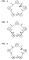
- the example of a network embodying the invention as shown in Figs.1 to 6 has five network nodes 10, 20, 30, 40 and 50 connected to each other in a ring topology via links 1-5. Link 5 between network node 10 and network node 50 is blocked, as indicated by the dotted lines.
- the shown example of a network is compliant with the Bridged Ethernet standards, also known in the art as the IEEE 802.3 and IEEE 802.1 standards. However, the invention is not limited to Bridged Ethernet networks and may also be applied in other types of networks.
- Network nodes 10-50 each have a memory (not shown) in which addressing information is stored as an address table providing an addressing scheme.
- the network nodes may perform a method according to the invention, for example the method illustrated by the flow-chart of Fig. 8.
- the method is initiated in step 101, for example by the detection of a link failure or the reception of a network change message which indicates that the addressing scheme, in the Ethernet network known as the spanning tree, should be reconfigured.
- link 2 between network nodes 20 and 30 may be physically damaged, for example because of a broken cable.
- both nodes 20 and 30 detect a link failure and initiate the method of Fig. 8 in step 101.
- step 102 the respective node blocks the link for which the failure is detected to another network node.
- nodes 20 and 30 block the link 2 by closing the ports (not shown) connected to link 2 on the respective node, as is indicated by the dotted line between nodes 20 and 30.
- step 103 the node sends a network change message (NCM) to a node directly connected to the node after or during the closing of the link.
- NCM network change message
- node 20 sends a NCM to adjacent node 10 via link 1 after closing link 2
- node 30 sends a NCM to adjacent node 40 via link 3 (Fig. 3).
- Steps 102 and 103 may be performed in the order shown and described, or they may be performed in reverse order, or they may be performed at the same time as each other.
- the flowchart of Fig. 8 divides into two branches, one comprising step 106, and the other comprising steps 107 and 108.
- the steps in one branch may be performed after, or before, or preferably, for the sake of speed, at the same time as the steps of the other branch.
- step 106 nodes 20 and 30 reconfigure the addressing information, in the example of Fig. 1 by at least partially erasing or flushing the, Bridged Ethernet compliant, address table.
- step 107 any old queued messages are also flushed by simply deleting them or waiting for their regular transmission to finish.
- nodes 20 and 30 send, in step 108, a reconfigured message (RM) to nodes 10 and 40, respectively, via links 1 and 3, respectively.
- RM reconfigured message
- nodes which are not directly connected to the failed link and are not connected to a blocked link are able to perform a method as illustrated in Fig. 9 in which, in step 101, the method is initiated with the reception of a NCM from another node.
- node 40 receives a NCM from node 30, as shown in Fig. 3.
- step 102 in reaction to the NCM, the respective node blocks the link over which the NCM was transmitted, as indicated in Fig. 4 by the dotted lines.
- node 40 blocks the port to link 3.
- step 103 which, as in Fig. 8, may be performed before, after, or at the same time as step 102, node 40 sends a NCM to adjacent node 50.
- step 106 node 40 reconfigures its addressing information by at least partially flushing its address table.
- step 107 as in step 107 of Fig. 8, the node also flushes any old queued messages, after which, in step 108, node 40 transmits a RM to a node directly connected to the respective node for links which are open.
- node 40 transmits a RM to node 50 as is shown in Fig. 6.
- step 104 node 40 checks if it has received a RM, and, if so, in step 105 node 40 de-blocks the respective link over which the RM was received (in this example the RM transmitted in step 108 of Fig. 8). Thus in the shown example, node 40 de-blocks the port to the blocked link 3.
- nodes which are directly connected to a blocked link are able to perform a method as illustrated in Fig. 10 in which, in step 101, the method is initiated with the reception of a NCM from another node.
- node 10 receives an NCM from adjacent node 20, as shown in Fig. 3
- node 50 receives an NCM from adjacent node 40, as shown in Fig. 4.
- step 102 in reaction to the NCM, the respective node blocks the link over which the NCM was received, as indicated in Fig. 4 and Fig. 5 by the dotted lines.
- node 10 blocks the port to link 1 and node 50 blocks the port to link 4.
- the flowchart of Fig. 10 divides into three branches, the first branch comprising step 106, the second branch comprising steps 107 and 109, and the third branch comprising step 104 and 105.
- the steps in one branch may be performed after, or before, or preferably, for the sake of speed, at the same time as the steps of the other branches.
- step 106 nodes 10 and 50 reconfigure the addressing information, in the example of Fig. 1 by at least partially erasing or flushing the, Bridged Ethernet compliant, address table.
- step 107 any old queued messages are also flushed by simply deleting them or waiting for their regular transmission to finish.
- step 109 the respective node de-blocks the link over which no NCM was transmitted.
- node 10 and node 50 de-block link 5, as is shown in Fig. 6.
- step 104 the respective nodes check if they have received an RM, and, if so, in step 105 the nodes de-block the respective links over which the RM was received.
- node 10 de-blocks link 1 after receiving the RM from node 20 as transmitted in step 108 of Fig. 8
- node 50 de-blocks link 4 after receiving the RM as transmitted in step 108 of Fig. 9.
- Fig. 7 shows a block diagram of an example of a network node 10 embodying the invention.
- the node 10 may, for example, be a general purpose computer, a router, a bridge or otherwise.
- the node has a data handler device 11 which is arranged to handle received data, for example by transmitting the data further, discarding the data or displaying the data.
- the data handler device 11 is communicatively connected to an input port 16 and an output port 17.
- a memory device 12 Connected to data handler device 11 is a memory device 12 in which information about the data is stored, for example as an address table or routing information.
- Also connected to data handler device 11 are a change detector 13 and an inhibitor device 14.
- the change detector 13 is also connected to an eraser device 15 which is connected to memory device 12.
- the change detector detects the necessity for changing the spanning tree, for example because detector 13 monitors the integrity of the links to which the input port 16 and the output port 17 are connected and/or detects the reception ofNCMs and/or RMs. If detector 13 finds that the spanning tree has to be changed, detector 13 will send a signal to inhibitor device 14 and eraser device 15 and sends a NCM to output port 17. Inhibitor device 14 then blocks one or more of the links connected to node 10, while eraser device 15 will at least partially erase the addressing information in memory 12. After having erased the addressing information, the eraser device will send a signal to detector 13. In reaction, detector 13 will send a RM to output port 17 via data handler 11 and also will send a signal to inhibitor device 14 to stop blocking the link.
- a method, network node, or computer program product according to the invention may be compliant with any networking protocol, for example, the Bridged Ethernet standards, and if the invention is applied in a Bridged Ethernet network, the NCM and the RM may be implemented as bridge protocol data units (BPDU), which are already provided for in the Bridged Ethernet protocols.
- BPDU bridge protocol data units
Landscapes
- Engineering & Computer Science (AREA)
- Computer Networks & Wireless Communication (AREA)
- Signal Processing (AREA)
- Small-Scale Networks (AREA)
- Data Exchanges In Wide-Area Networks (AREA)
Claims (4)
- Verfahren (Fig. 8) zum Rekonfigurieren eines Netzwerks aus Knoten, die physisch zu einem Ring verbunden sind, der wenigstens drei Knoten (10, 20, 30, 40, 50) aufweist, die durch mehrere Verknüpfungen (1, 2, 3, 4, 5) zu dem Netzwerk verbunden sind, wobei das Verfahren an einem ersten Knoten (40) der wenigstens drei Knoten Folgendes aufweist:Rekonfigurieren (Fig. 3) des ersten Knotens (40) in Reaktion auf den Erhalt einer Netzwerkänderungsmeldung (NCM), die von einem ersten benachbarten Knoten (30) neben dem ersten Knoten (40) erhalten wurde, durch:selektives Blockieren (Fig. 4) der Verknüpfung (3), über die die NCM erhalten wurde, dergestalt, dass keine Wartungsmeldungen blockiert werden, wobei die Wartungsmeldungen rekonfigurierte Meldungen (RMs) aufweisen;Senden (Fig. 5) einer NCM an einen zweiten benachbarten Knoten (50) neben dem ersten Knoten (40);Rekonfigurieren von Adressinformationen in dem ersten Knoten (40) durch wenigstens teilweises Entfernen (106) von Adressinformationen in dem ersten Knoten (40);Entfernen aus dem ersten Knoten (40) aller zuvor in einer Schlange eingereihten Meldungen (107), die in dem ersten Knoten (40) gespeichert sind;Übermitteln (Fig. 6) einer rekonfigurierten Meldung (RM) (108) an den zweiten benachbarten Knoten (50) in Reaktion auf die Vollendung des Entfernens (107) aus dem ersten Knoten (40) aller zuvor in einer Schlange eingereihten Meldungen (107), die in dem ersten Knoten (40) gespeichert sind; undAufheben der Blockierung (108, Fig. 5) der Verknüpfung (3), über die die NCM erhalten wurde, in Reaktion auf eine RM, die von dem ersten benachbarten Knoten (30) erhalten wurde (104).
- Verfahren (Fig. 9) nach Anspruch 1, das des Weiteren an einem zweiten Knoten (20), wobei der zweite Knoten (20) mit einer ausgefallenen Verknüpfung verbunden ist, Folgendes aufweist:Rekonfigurieren des zweiten Knotens (20) in Reaktion auf das Erkennen eines Ausfalls der Verknüpfung durch:Senden (103, Fig. 3) einer NCM an einen dritten benachbarten Knoten (10) neben dem zweiten Knoten (20) am anderen Ende der nicht-ausgefallenen Verknüpfung, die mit dem zweiten Knoten (20) verbunden ist;Blockieren der ausgefallenen Verknüpfung (Fig. 4:2);Rekonfigurieren (106) von Adressinformationen in dem zweiten Knoten (20) durch wenigstens teilweises Entfernen von Adressinformationen, die in dem zweiten Knoten (20) gespeichert sind;Entfernen (107) aus dem zweiten Knoten (20) aller zuvor in einer Schlange eingereihten Meldungen, die in dem zweiten Knoten (20) gespeichert sind; undÜbermitteln (Fig. 5) einer RM an den dritten benachbarten Knoten (10) in Reaktion auf die Vollendung des Entfernens aus dem zweiten Knoten (20) aller zuvor in einer Schlange eingereihten Meldungen, die in dem zweiten Knoten (20) gespeichert sind.
- Verfahren (Fig. 10) nach Anspruch 1, das des Weiteren an einem zweiten Knoten (10), der mit einer blockierten Verknüpfung (5) verbunden ist, Folgendes aufweist:Rekonfigurieren des zweiten Knotens (10) in Reaktion (Fig. 3) auf den Erhalt einer NCM von einem dritten benachbarten Knoten (20) neben dem zweiten Knoten (10) durch:selektives Blockieren der Verknüpfung (1), über die die NCM erhalten wurde, dergestalt, dass keine Wartungsmeldungen blockiert werden, wobei die Wartungsmeldungen rekonfigurierte Meldungen (RMs) aufweisen;Rekonfigurieren von Adressinformationen in dem zweiten Knoten (10) durch wenigstens teilweises Entfernen von Adressinformationen, die in dem zweiten Knoten (10) gespeichert sind;Entfernen aus dem zweiten Knoten (10) aller zuvor in einer Schlange eingereihten Meldungen, die in dem zweiten Knoten (10) gespeichert sind;Aufheben der Blockierung der blockierten Verknüpfung (5) in Reaktion auf die Vollendung des Entfernens aus dem zweiten Knoten (10) aller zuvor in einer Schlange eingereihten Meldungen, die in dem zweiten Knoten (10) gespeichert sind; undAufheben der Blockierung der Verknüpfung (1), über die die NCM erhalten wurde, in Reaktion auf eine RM, die von dem dritten benachbarten Knoten (20) erhalten wurde.
- Verfahren nach Anspruch 1, 2 oder 3, wobei das Netzwerk einem Ethernet-Standard entspricht.
Applications Claiming Priority (2)
| Application Number | Priority Date | Filing Date | Title |
|---|---|---|---|
| US452626 | 2003-06-02 | ||
| US10/452,626 US8543672B2 (en) | 2003-06-02 | 2003-06-02 | Method for reconfiguring a ring network, a network node, and a computer program product |
Publications (2)
| Publication Number | Publication Date |
|---|---|
| EP1487158A1 EP1487158A1 (de) | 2004-12-15 |
| EP1487158B1 true EP1487158B1 (de) | 2006-07-12 |
Family
ID=33299593
Family Applications (1)
| Application Number | Title | Priority Date | Filing Date |
|---|---|---|---|
| EP04253184A Expired - Lifetime EP1487158B1 (de) | 2003-06-02 | 2004-05-28 | Verfahren zur Rekonfiguration eines Ringnetzes |
Country Status (5)
| Country | Link |
|---|---|
| US (1) | US8543672B2 (de) |
| EP (1) | EP1487158B1 (de) |
| JP (1) | JP4372618B2 (de) |
| KR (1) | KR101094049B1 (de) |
| DE (1) | DE602004001489T2 (de) |
Families Citing this family (6)
| Publication number | Priority date | Publication date | Assignee | Title |
|---|---|---|---|---|
| US7688716B2 (en) * | 2005-05-02 | 2010-03-30 | Cisco Technology, Inc. | Method, apparatus, and system for improving ethernet ring convergence time |
| US7948922B2 (en) * | 2006-04-18 | 2011-05-24 | Cisco Technology, Inc. | Blocked redundant link-aware spanning tree protocol enhancement |
| CN101141366A (zh) * | 2006-09-07 | 2008-03-12 | 华为技术有限公司 | 一种在环状以太网中避免数据环路的方法 |
| US20090016214A1 (en) * | 2007-07-12 | 2009-01-15 | Allied Telesis Holdings K.K. | Method and system for network recovery from multiple link failures |
| JP4977190B2 (ja) * | 2009-11-12 | 2012-07-18 | 富士通テレコムネットワークス株式会社 | 通信装置、インターフェースカードおよび障害対処方法 |
| JP5581141B2 (ja) * | 2010-07-29 | 2014-08-27 | 株式会社Pfu | 管理サーバ、通信遮断装置、情報処理システム、方法およびプログラム |
Family Cites Families (15)
| Publication number | Priority date | Publication date | Assignee | Title |
|---|---|---|---|---|
| US4683563A (en) | 1984-10-11 | 1987-07-28 | American Telephone And Telegraph Company, At&T Bell Laboratories | Data communication network |
| US6091705A (en) * | 1996-12-20 | 2000-07-18 | Sebring Systems, Inc. | Method and apparatus for a fault tolerant, software transparent and high data integrity extension to a backplane bus or interconnect |
| US6976088B1 (en) * | 1997-12-24 | 2005-12-13 | Cisco Technology, Inc. | Method and apparatus for rapidly reconfiguring bridged networks using a spanning tree algorithm |
| US6032194A (en) * | 1997-12-24 | 2000-02-29 | Cisco Technology, Inc. | Method and apparatus for rapidly reconfiguring computer networks |
| US6330229B1 (en) * | 1998-11-09 | 2001-12-11 | 3Com Corporation | Spanning tree with rapid forwarding database updates |
| US6606301B1 (en) * | 1999-03-01 | 2003-08-12 | Sun Microsystems, Inc. | Method and apparatus for early random discard of packets |
| US6535490B1 (en) | 1999-03-04 | 2003-03-18 | 3Com Corporation | High availability spanning tree with rapid reconfiguration with alternate port selection |
| US6731596B1 (en) * | 1999-04-01 | 2004-05-04 | Advanced Micro Devices, Inc. | Network switch having system for automatically detecting change in network node connection |
| US6952396B1 (en) * | 1999-09-27 | 2005-10-04 | Nortel Networks Limited | Enhanced dual counter rotating ring network control system |
| US6973229B1 (en) * | 2001-02-28 | 2005-12-06 | Lambda Opticalsystems Corporation | Node architecture for modularized and reconfigurable optical networks, and methods and apparatus therefor |
| JP2002330152A (ja) * | 2001-04-27 | 2002-11-15 | Fujitsu Ltd | 障害時/増設時におけるスパニングツリー制御装置及び方法 |
| US7362709B1 (en) * | 2001-11-02 | 2008-04-22 | Arizona Board Of Regents | Agile digital communication network with rapid rerouting |
| US7496650B1 (en) * | 2003-01-09 | 2009-02-24 | Cisco Technology, Inc. | Identifying and suppressing transient routing updates |
| US20040160895A1 (en) * | 2003-02-14 | 2004-08-19 | At&T Corp. | Failure notification method and system in an ethernet domain |
| US20040165595A1 (en) * | 2003-02-25 | 2004-08-26 | At&T Corp. | Discovery and integrity testing method in an ethernet domain |
-
2003
- 2003-06-02 US US10/452,626 patent/US8543672B2/en not_active Expired - Fee Related
-
2004
- 2004-05-28 EP EP04253184A patent/EP1487158B1/de not_active Expired - Lifetime
- 2004-05-28 DE DE602004001489T patent/DE602004001489T2/de not_active Expired - Lifetime
- 2004-06-01 KR KR1020040039592A patent/KR101094049B1/ko not_active Expired - Fee Related
- 2004-06-02 JP JP2004164581A patent/JP4372618B2/ja not_active Expired - Fee Related
Also Published As
| Publication number | Publication date |
|---|---|
| KR101094049B1 (ko) | 2011-12-19 |
| US8543672B2 (en) | 2013-09-24 |
| US20050015470A1 (en) | 2005-01-20 |
| EP1487158A1 (de) | 2004-12-15 |
| JP2004364302A (ja) | 2004-12-24 |
| DE602004001489T2 (de) | 2007-07-05 |
| JP4372618B2 (ja) | 2009-11-25 |
| KR20040103787A (ko) | 2004-12-09 |
| DE602004001489D1 (de) | 2006-08-24 |
Similar Documents
| Publication | Publication Date | Title |
|---|---|---|
| US8199636B1 (en) | Bridged network system with traffic resiliency upon link failure | |
| US7027390B2 (en) | Packet routing apparatus and a method of communicating a packet | |
| US8699380B2 (en) | Port table flushing in ethernet networks | |
| JP4008923B2 (ja) | フォルトトレラントネットワークルーティング | |
| EP2150007B1 (de) | Umleitung auf Mac-Schicht 2 | |
| US7339888B2 (en) | Bridge and route change method of network using the same | |
| US20100284416A1 (en) | Network relay device and ring network | |
| US8687523B2 (en) | System and method for integrating ring-protocol-compatible devices into network configurations that also include non-ring-protocol compatible devices | |
| EP1480397B1 (de) | Erweiterungen des Spanning-Tree-Protokolls | |
| CN111886834A (zh) | 用于网段间通信的系统、方法和设备 | |
| US20200044964A1 (en) | Defect detection in ip/mpls network tunnels | |
| EP1487158B1 (de) | Verfahren zur Rekonfiguration eines Ringnetzes | |
| US20030161275A1 (en) | Spanning tree method | |
| JP2008167315A (ja) | 回線冗長接続方法および広域通信網ノード装置 | |
| CN104780138B (zh) | 私有冗余协议网络中stp/rstp报文的透传方法及装置 | |
| KR20180028291A (ko) | 이더넷 프레임 기반의 트래픽 제어 방법 | |
| CN101227368B (zh) | 分布式环网的组网方法 | |
| EP2898636B1 (de) | Verfahren zum betreiben eines computernetzwerks | |
| KR101992713B1 (ko) | 통신 인터페이스 장치 | |
| CN113875196B (zh) | 通信装置 | |
| CN107360075B (zh) | 网络设备环保护方法及其装置、网络系统 | |
| JP2001053772A (ja) | 分岐挿入ノード、それを複数接続したリングネットワークおよびリングネットワークの障害復旧方法 | |
| JP2004229152A (ja) | 回線切替装置及びデータ伝送システム及び回線切替方法 | |
| JPH11205367A (ja) | パケットの無限中継検出・除去方法及びそのネットワーク装置 | |
| JPH05268221A (ja) | Lan間接続装置のフレーム中継方式 |
Legal Events
| Date | Code | Title | Description |
|---|---|---|---|
| PUAI | Public reference made under article 153(3) epc to a published international application that has entered the european phase |
Free format text: ORIGINAL CODE: 0009012 |
|
| 17P | Request for examination filed |
Effective date: 20040614 |
|
| AK | Designated contracting states |
Kind code of ref document: A1 Designated state(s): AT BE BG CH CY CZ DE DK EE ES FI FR GB GR HU IE IT LI LU MC NL PL PT RO SE SI SK TR |
|
| AX | Request for extension of the european patent |
Extension state: AL HR LT LV MK |
|
| 17Q | First examination report despatched |
Effective date: 20050217 |
|
| AKX | Designation fees paid |
Designated state(s): DE FR GB |
|
| GRAP | Despatch of communication of intention to grant a patent |
Free format text: ORIGINAL CODE: EPIDOSNIGR1 |
|
| RTI1 | Title (correction) |
Free format text: METHOD FOR RECONFIGURING A RING NETWORK |
|
| GRAS | Grant fee paid |
Free format text: ORIGINAL CODE: EPIDOSNIGR3 |
|
| GRAA | (expected) grant |
Free format text: ORIGINAL CODE: 0009210 |
|
| AK | Designated contracting states |
Kind code of ref document: B1 Designated state(s): DE FR GB |
|
| REG | Reference to a national code |
Ref country code: GB Ref legal event code: FG4D |
|
| REF | Corresponds to: |
Ref document number: 602004001489 Country of ref document: DE Date of ref document: 20060824 Kind code of ref document: P |
|
| ET | Fr: translation filed | ||
| PLBE | No opposition filed within time limit |
Free format text: ORIGINAL CODE: 0009261 |
|
| STAA | Information on the status of an ep patent application or granted ep patent |
Free format text: STATUS: NO OPPOSITION FILED WITHIN TIME LIMIT |
|
| 26N | No opposition filed |
Effective date: 20070413 |
|
| REG | Reference to a national code |
Ref country code: GB Ref legal event code: 732E Free format text: REGISTERED BETWEEN 20131121 AND 20131127 |
|
| REG | Reference to a national code |
Ref country code: FR Ref legal event code: CD Owner name: ALCATEL-LUCENT USA INC. Effective date: 20131122 |
|
| REG | Reference to a national code |
Ref country code: FR Ref legal event code: GC Effective date: 20140410 |
|
| REG | Reference to a national code |
Ref country code: FR Ref legal event code: RG Effective date: 20141015 |
|
| REG | Reference to a national code |
Ref country code: FR Ref legal event code: PLFP Year of fee payment: 12 |
|
| REG | Reference to a national code |
Ref country code: FR Ref legal event code: PLFP Year of fee payment: 13 |
|
| REG | Reference to a national code |
Ref country code: FR Ref legal event code: PLFP Year of fee payment: 14 |
|
| PGFP | Annual fee paid to national office [announced via postgrant information from national office to epo] |
Ref country code: GB Payment date: 20170519 Year of fee payment: 14 Ref country code: DE Payment date: 20170523 Year of fee payment: 14 Ref country code: FR Payment date: 20170523 Year of fee payment: 14 |
|
| REG | Reference to a national code |
Ref country code: DE Ref legal event code: R119 Ref document number: 602004001489 Country of ref document: DE |
|
| GBPC | Gb: european patent ceased through non-payment of renewal fee |
Effective date: 20180528 |
|
| REG | Reference to a national code |
Ref country code: GB Ref legal event code: 732E Free format text: REGISTERED BETWEEN 20190131 AND 20190206 |
|
| PG25 | Lapsed in a contracting state [announced via postgrant information from national office to epo] |
Ref country code: GB Free format text: LAPSE BECAUSE OF NON-PAYMENT OF DUE FEES Effective date: 20180528 Ref country code: FR Free format text: LAPSE BECAUSE OF NON-PAYMENT OF DUE FEES Effective date: 20180531 Ref country code: DE Free format text: LAPSE BECAUSE OF NON-PAYMENT OF DUE FEES Effective date: 20181201 |