EP1486962A1 - Optical recording medium, its recording/reproducing apparatus, its storage apparatus, and its recording/reproducing method - Google Patents
Optical recording medium, its recording/reproducing apparatus, its storage apparatus, and its recording/reproducing method Download PDFInfo
- Publication number
- EP1486962A1 EP1486962A1 EP02701602A EP02701602A EP1486962A1 EP 1486962 A1 EP1486962 A1 EP 1486962A1 EP 02701602 A EP02701602 A EP 02701602A EP 02701602 A EP02701602 A EP 02701602A EP 1486962 A1 EP1486962 A1 EP 1486962A1
- Authority
- EP
- European Patent Office
- Prior art keywords
- optical
- recording medium
- recording
- near field
- film
- Prior art date
- Legal status (The legal status is an assumption and is not a legal conclusion. Google has not performed a legal analysis and makes no representation as to the accuracy of the status listed.)
- Withdrawn
Links
Images








Classifications
-
- G—PHYSICS
- G11—INFORMATION STORAGE
- G11B—INFORMATION STORAGE BASED ON RELATIVE MOVEMENT BETWEEN RECORD CARRIER AND TRANSDUCER
- G11B7/00—Recording or reproducing by optical means, e.g. recording using a thermal beam of optical radiation by modifying optical properties or the physical structure, reproducing using an optical beam at lower power by sensing optical properties; Record carriers therefor
- G11B7/24—Record carriers characterised by shape, structure or physical properties, or by the selection of the material
- G11B7/2407—Tracks or pits; Shape, structure or physical properties thereof
- G11B7/24073—Tracks
- G11B7/24076—Cross sectional shape in the radial direction of a disc, e.g. asymmetrical cross sectional shape
-
- G—PHYSICS
- G11—INFORMATION STORAGE
- G11B—INFORMATION STORAGE BASED ON RELATIVE MOVEMENT BETWEEN RECORD CARRIER AND TRANSDUCER
- G11B7/00—Recording or reproducing by optical means, e.g. recording using a thermal beam of optical radiation by modifying optical properties or the physical structure, reproducing using an optical beam at lower power by sensing optical properties; Record carriers therefor
- G11B7/24—Record carriers characterised by shape, structure or physical properties, or by the selection of the material
- G11B7/2407—Tracks or pits; Shape, structure or physical properties thereof
- G11B7/24073—Tracks
- G11B7/24079—Width or depth
-
- G—PHYSICS
- G11—INFORMATION STORAGE
- G11B—INFORMATION STORAGE BASED ON RELATIVE MOVEMENT BETWEEN RECORD CARRIER AND TRANSDUCER
- G11B11/00—Recording on or reproducing from the same record carrier wherein for these two operations the methods are covered by different main groups of groups G11B3/00 - G11B7/00 or by different subgroups of group G11B9/00; Record carriers therefor
- G11B11/10—Recording on or reproducing from the same record carrier wherein for these two operations the methods are covered by different main groups of groups G11B3/00 - G11B7/00 or by different subgroups of group G11B9/00; Record carriers therefor using recording by magnetic means or other means for magnetisation or demagnetisation of a record carrier, e.g. light induced spin magnetisation; Demagnetisation by thermal or stress means in the presence or not of an orienting magnetic field
- G11B11/105—Recording on or reproducing from the same record carrier wherein for these two operations the methods are covered by different main groups of groups G11B3/00 - G11B7/00 or by different subgroups of group G11B9/00; Record carriers therefor using recording by magnetic means or other means for magnetisation or demagnetisation of a record carrier, e.g. light induced spin magnetisation; Demagnetisation by thermal or stress means in the presence or not of an orienting magnetic field using a beam of light or a magnetic field for recording by change of magnetisation and a beam of light for reproducing, i.e. magneto-optical, e.g. light-induced thermomagnetic recording, spin magnetisation recording, Kerr or Faraday effect reproducing
-
- G—PHYSICS
- G11—INFORMATION STORAGE
- G11B—INFORMATION STORAGE BASED ON RELATIVE MOVEMENT BETWEEN RECORD CARRIER AND TRANSDUCER
- G11B11/00—Recording on or reproducing from the same record carrier wherein for these two operations the methods are covered by different main groups of groups G11B3/00 - G11B7/00 or by different subgroups of group G11B9/00; Record carriers therefor
- G11B11/10—Recording on or reproducing from the same record carrier wherein for these two operations the methods are covered by different main groups of groups G11B3/00 - G11B7/00 or by different subgroups of group G11B9/00; Record carriers therefor using recording by magnetic means or other means for magnetisation or demagnetisation of a record carrier, e.g. light induced spin magnetisation; Demagnetisation by thermal or stress means in the presence or not of an orienting magnetic field
- G11B11/105—Recording on or reproducing from the same record carrier wherein for these two operations the methods are covered by different main groups of groups G11B3/00 - G11B7/00 or by different subgroups of group G11B9/00; Record carriers therefor using recording by magnetic means or other means for magnetisation or demagnetisation of a record carrier, e.g. light induced spin magnetisation; Demagnetisation by thermal or stress means in the presence or not of an orienting magnetic field using a beam of light or a magnetic field for recording by change of magnetisation and a beam of light for reproducing, i.e. magneto-optical, e.g. light-induced thermomagnetic recording, spin magnetisation recording, Kerr or Faraday effect reproducing
- G11B11/10532—Heads
-
- G—PHYSICS
- G11—INFORMATION STORAGE
- G11B—INFORMATION STORAGE BASED ON RELATIVE MOVEMENT BETWEEN RECORD CARRIER AND TRANSDUCER
- G11B5/00—Recording by magnetisation or demagnetisation of a record carrier; Reproducing by magnetic means; Record carriers therefor
- G11B5/127—Structure or manufacture of heads, e.g. inductive
- G11B5/31—Structure or manufacture of heads, e.g. inductive using thin films
- G11B5/3109—Details
- G11B5/313—Disposition of layers
- G11B5/3133—Disposition of layers including layers not usually being a part of the electromagnetic transducer structure and providing additional features, e.g. for improving heat radiation, reduction of power dissipation, adaptations for measurement or indication of gap depth or other properties of the structure
- G11B5/314—Disposition of layers including layers not usually being a part of the electromagnetic transducer structure and providing additional features, e.g. for improving heat radiation, reduction of power dissipation, adaptations for measurement or indication of gap depth or other properties of the structure where the layers are extra layers normally not provided in the transducing structure, e.g. optical layers
-
- G—PHYSICS
- G11—INFORMATION STORAGE
- G11B—INFORMATION STORAGE BASED ON RELATIVE MOVEMENT BETWEEN RECORD CARRIER AND TRANSDUCER
- G11B7/00—Recording or reproducing by optical means, e.g. recording using a thermal beam of optical radiation by modifying optical properties or the physical structure, reproducing using an optical beam at lower power by sensing optical properties; Record carriers therefor
- G11B7/004—Recording, reproducing or erasing methods; Read, write or erase circuits therefor
-
- G—PHYSICS
- G11—INFORMATION STORAGE
- G11B—INFORMATION STORAGE BASED ON RELATIVE MOVEMENT BETWEEN RECORD CARRIER AND TRANSDUCER
- G11B7/00—Recording or reproducing by optical means, e.g. recording using a thermal beam of optical radiation by modifying optical properties or the physical structure, reproducing using an optical beam at lower power by sensing optical properties; Record carriers therefor
- G11B7/12—Heads, e.g. forming of the optical beam spot or modulation of the optical beam
-
- G—PHYSICS
- G11—INFORMATION STORAGE
- G11B—INFORMATION STORAGE BASED ON RELATIVE MOVEMENT BETWEEN RECORD CARRIER AND TRANSDUCER
- G11B7/00—Recording or reproducing by optical means, e.g. recording using a thermal beam of optical radiation by modifying optical properties or the physical structure, reproducing using an optical beam at lower power by sensing optical properties; Record carriers therefor
- G11B7/12—Heads, e.g. forming of the optical beam spot or modulation of the optical beam
- G11B7/135—Means for guiding the beam from the source to the record carrier or from the record carrier to the detector
-
- G—PHYSICS
- G11—INFORMATION STORAGE
- G11B—INFORMATION STORAGE BASED ON RELATIVE MOVEMENT BETWEEN RECORD CARRIER AND TRANSDUCER
- G11B7/00—Recording or reproducing by optical means, e.g. recording using a thermal beam of optical radiation by modifying optical properties or the physical structure, reproducing using an optical beam at lower power by sensing optical properties; Record carriers therefor
- G11B7/12—Heads, e.g. forming of the optical beam spot or modulation of the optical beam
- G11B7/135—Means for guiding the beam from the source to the record carrier or from the record carrier to the detector
- G11B7/1387—Means for guiding the beam from the source to the record carrier or from the record carrier to the detector using the near-field effect
-
- G—PHYSICS
- G11—INFORMATION STORAGE
- G11B—INFORMATION STORAGE BASED ON RELATIVE MOVEMENT BETWEEN RECORD CARRIER AND TRANSDUCER
- G11B7/00—Recording or reproducing by optical means, e.g. recording using a thermal beam of optical radiation by modifying optical properties or the physical structure, reproducing using an optical beam at lower power by sensing optical properties; Record carriers therefor
- G11B7/12—Heads, e.g. forming of the optical beam spot or modulation of the optical beam
- G11B7/14—Heads, e.g. forming of the optical beam spot or modulation of the optical beam specially adapted to record on, or to reproduce from, more than one track simultaneously
-
- G—PHYSICS
- G11—INFORMATION STORAGE
- G11B—INFORMATION STORAGE BASED ON RELATIVE MOVEMENT BETWEEN RECORD CARRIER AND TRANSDUCER
- G11B7/00—Recording or reproducing by optical means, e.g. recording using a thermal beam of optical radiation by modifying optical properties or the physical structure, reproducing using an optical beam at lower power by sensing optical properties; Record carriers therefor
- G11B7/24—Record carriers characterised by shape, structure or physical properties, or by the selection of the material
-
- G—PHYSICS
- G11—INFORMATION STORAGE
- G11B—INFORMATION STORAGE BASED ON RELATIVE MOVEMENT BETWEEN RECORD CARRIER AND TRANSDUCER
- G11B11/00—Recording on or reproducing from the same record carrier wherein for these two operations the methods are covered by different main groups of groups G11B3/00 - G11B7/00 or by different subgroups of group G11B9/00; Record carriers therefor
- G11B11/10—Recording on or reproducing from the same record carrier wherein for these two operations the methods are covered by different main groups of groups G11B3/00 - G11B7/00 or by different subgroups of group G11B9/00; Record carriers therefor using recording by magnetic means or other means for magnetisation or demagnetisation of a record carrier, e.g. light induced spin magnetisation; Demagnetisation by thermal or stress means in the presence or not of an orienting magnetic field
- G11B11/105—Recording on or reproducing from the same record carrier wherein for these two operations the methods are covered by different main groups of groups G11B3/00 - G11B7/00 or by different subgroups of group G11B9/00; Record carriers therefor using recording by magnetic means or other means for magnetisation or demagnetisation of a record carrier, e.g. light induced spin magnetisation; Demagnetisation by thermal or stress means in the presence or not of an orienting magnetic field using a beam of light or a magnetic field for recording by change of magnetisation and a beam of light for reproducing, i.e. magneto-optical, e.g. light-induced thermomagnetic recording, spin magnetisation recording, Kerr or Faraday effect reproducing
- G11B11/10582—Record carriers characterised by the selection of the material or by the structure or form
- G11B11/10584—Record carriers characterised by the selection of the material or by the structure or form characterised by the form, e.g. comprising mechanical protection elements
-
- G—PHYSICS
- G11—INFORMATION STORAGE
- G11B—INFORMATION STORAGE BASED ON RELATIVE MOVEMENT BETWEEN RECORD CARRIER AND TRANSDUCER
- G11B5/00—Recording by magnetisation or demagnetisation of a record carrier; Reproducing by magnetic means; Record carriers therefor
- G11B2005/0002—Special dispositions or recording techniques
- G11B2005/0005—Arrangements, methods or circuits
-
- G—PHYSICS
- G11—INFORMATION STORAGE
- G11B—INFORMATION STORAGE BASED ON RELATIVE MOVEMENT BETWEEN RECORD CARRIER AND TRANSDUCER
- G11B5/00—Recording by magnetisation or demagnetisation of a record carrier; Reproducing by magnetic means; Record carriers therefor
- G11B2005/0002—Special dispositions or recording techniques
- G11B2005/0005—Arrangements, methods or circuits
- G11B2005/0021—Thermally assisted recording using an auxiliary energy source for heating the recording layer locally to assist the magnetization reversal
-
- G—PHYSICS
- G11—INFORMATION STORAGE
- G11B—INFORMATION STORAGE BASED ON RELATIVE MOVEMENT BETWEEN RECORD CARRIER AND TRANSDUCER
- G11B7/00—Recording or reproducing by optical means, e.g. recording using a thermal beam of optical radiation by modifying optical properties or the physical structure, reproducing using an optical beam at lower power by sensing optical properties; Record carriers therefor
- G11B7/24—Record carriers characterised by shape, structure or physical properties, or by the selection of the material
- G11B7/2403—Layers; Shape, structure or physical properties thereof
- G11B7/24035—Recording layers
- G11B7/24038—Multiple laminated recording layers
Definitions
- the present invention generally relates to an optical recording medium, a memory apparatus, and a recording/reproduction method, more particularly, a high density optical recording medium, a memory apparatus, and a recording/reproduction method that use optical near field.
- a conventional optical head for an optical disk light is condensed by using a lens.
- the amount of information that can be recorded onto the optical disk depends on the diameter of the condensed beam.
- the diameter of such condensed beam is confined to the wavelength of the laser beam for recording and/or reproducing information to/from the optical disk, and by the numerical aperture (NA) of the optical lens system.
- NA numerical aperture
- a method for recording information onto an optical disk medium in which a numerical aperture (NA) of 1 or more is obtained by employing a SIL (Solid Immersion Lens) and utilizing the evanescent light leaking from the bottom of the SIL.
- NA numerical aperture
- recording information onto the optical disk medium by utilizing the evanescent light requires the distance between the SIL and the recording surface of the optical disk to be maintained at no more than 1/10 of the wavelength. Therefore, precise control is required for maintaining a constant distance between the optical disk and the SIL.
- dust may adhere to the optical disk to cause contact with the SIL. The problem of dust causes difficulty in attaining removability, which is one of the benefits of the optical disk.
- NA numerical aperture
- an optical fiber optical fiber probe
- the optical fiber probe is manufactured by applying metal coating to portions other than its tip portion after heating and stretching an end of an optical fiber or after tapering an optical fiber with a chemical etching method. Accordingly, by directing an incident laser beam on the optical fiber probe, an optical near field can be generated at the proximity of the fine opening formed at the tip portion.
- the optical fiber probe has a drawback of inefficient utilization of light.
- the aperture diameter is 100 nm
- the ratio of the optical strength of the incident laser beam on the optical fiber probe to the laser beam emitted from the tip portion of the optical fiber probe becomes 0.001% or less, thereby resulting to an emitted laser beam with considerably low optical strength.
- the below-given optical near field probes are proposed.
- the first probe is a multi-level taper optical fiber probe.
- This optical fiber probe is described in "Applied Physics Letters” (Vol.68, No.19, p. 2612-2614) issued in 1996, and "Applied Physics Letters” (Vol.73, No.15, p. 2090-2092) issued in 1998.
- This optical fiber probe has its pointed tip formed in two or three varying levels from its root portion to its tip portion.
- the next probe is a metal needle probe.
- This probe is described in Japanese Laid-Open Patent Application No.6-137847, in which light is irradiated to a tip of a needle for generating an optical near field in proximity to the tip portion.
- the next probe is a fine aperture fiber probe with a fine metal sphere.
- This fiber probe is described in Japanese Laid-Open Patent Application No.11-101809, in which a fine metal sphere is formed at a center of a fine aperture of a tip portion of the fiber probe.
- an optical near field is generated by irradiating light from the fine aperture and thereby exciting plasmon in the fine metal sphere.
- the next probe is a probe with a metal coated glass segment.
- This probe is described in "Physical Review B” (Vol.55, No.12, p.7977-7984) issued in 1997.
- This probe has a metal film with a thickness of approximately 50 nm formed on a triangularly cut-out glass segment, in which surface plasmon is excited on the metal film. Accordingly, since the excited surface plasmon is propagated toward the tip of the probe, a strong optical near field is generated in proximity to the tip.
- the next probe is a glass substrate probe with a metal scatterer.
- This probe is described in Japanese Laid-Open Patent Application No.11-250460 This is a probe having a metal scatterer attached to a bottom portion of a glass substrate. By attaching the metal scatterer, a strong optical near field is generated in proximity to the metal scatterer.
- a particular control system is necessary for precisely controlling the space between the tip portion of the probe and the recording surface.
- This control system measures the space between the tip portion of the probe and the recording surface by measuring the atomic force between the tip portion of the probe and the recording surface, and servo controls the position of the probe so that the measured value is constant.
- the relative scanning speed of the probe with respect to a recording medium is to be no more than a prescribed speed with an error no more than a prescribed value.
- the servo control system may be unable to provide sufficient control since the probe is required to trace large disturbances with high frequency amplitude. In order to solve the problem, the below described probe is proposed.
- the first probe is a flat aperture optic fiber probe.
- This optical fiber probe is described in "Electronics and Communications in Japan” (Part 2, Vol.81, No.8, p.41-48) issued in 1998 (translated from “Journal of The Institute of Electronics, Information, and Communication Engineers Vol.J81-C-I, No.3, p.119-126).
- This probe has an aperture formed by applying an anisotropic etching technique to a silicon substrate. Since the portion surrounding the aperture is flat, the distance between the tip portion of the probe and the recording surface can be maintained constant when the probe approaches the recording medium.
- the next probe is a pad aperture probe.
- This probe is described in Japanese Laid-Open Patent Application No.11-265520.
- This probe has a quadrangular pyramid-shaped protrusion with a fine aperture formed at a tip portion thereof, and also has a pad formed at a surrounding portion of the protrusion. The pad serves to maintain the distance between the tip portion of the probe and the recording surface constant.
- the next probe is a plane illumination laser probe with a fine metal chip.
- This probe is described in "Applied Physics” (Vol.68, No.12, p.1380-1383) issued in 1999.
- This probe has a fine metal protrusion with a fine aperture formed at an end face of the plane illumination laser port. Since the probe has a flat structure, the distance between the tip portion of the probe and the recording surface can be maintained constant when the probe approaches the recording medium.
- the three below given factors are required to be satisfied.
- the beam spot of the generated optical near field is required to be of a fine size.
- Third, the generated optical near field is required to be of high light use efficiency.
- the above-described multi-stage pointed optical fiber probe has a light use efficiency which is approximately 10 to 100 times higher than that of a typically used fiber probe, but is still insufficient to be applied for optical recording/reproduction, which requires a high light use efficiency of 10% or more. In addition, it is mechanically fragile, and is especially vulnerable in high speed scanning since optical fiber is used.
- the metal needle probe, the fine aperture fiber probe with a fine metal sphere, the probe with a metal coated glass segment, and the glass substrate probe with a metal scatterer are able to attain high light use efficiency by utilizing their metal property. All of them, however, are formed with a mechanically fragile tip, and are, therefore, particularly vulnerable in high speed scanning. Particularly, the metal pin probe and the glass substrate probe with a metal scatterer have a problem in that a large amount of background light is detected therefrom since the light that is irradiated neither to the tip of the needle nor the scatterer becomes incident on the recording medium.
- the plane illumination laser probe with a fine metal chip is expected to provide high speed scanning performance, high light use efficiency, and little background light.
- the form of the metal is to be optimized. Nevertheless, neither the form nor the method of manufacture is disclosed.
- the lens uses, for example, TiO 2 as its material since a refractive index of 2.7 is required. With such material, however, light cannot pass through in a case of employing a blue-violet laser diode (LD) with a wavelength of 410 nm. Accordingly, the method cannot be applied to a short wavelength laser diode, and cannot attain high recording density.
- LD blue-violet laser diode
- the present invention aims to provide a high density optical recording medium, a memory apparatus, a high density recording/reproduction method, and a manufacturing method of a high density optical recording medium that obviate the problems caused by the related art.
- the present invention provides an optical recording medium having at least a recording film and a protection film disposed on a substrate, the optical recording medium including: a plurality of recording tracks being disposed, along a predetermined direction, on a signal recording surface to which a laser beam is incident, the recording tracks having tapered protruding portions; wherein the protruding portions are formed of an optical near field generation film.
- an optical near field generation film for intensifying electric field can be buried in the optical disk medium, and the distance between the optical near field generation film and the recording film can be defined when forming the films in a process of optical disk manufacture. Furthermore, by using a conventional sputtering apparatus or the like, the distance between the films can be precisely controlled in nanometer (nm) sizes. Accordingly, as long as a laser beam is controlled to condense at the tip portion of the optical near field generation film by using an optical system of a typical optical disk apparatus, an optical near field can be generated in an area situated at a predetermined distance apart from the tip portion of the optical near field generation film buried in the optical disk, thereby enabling the generated optical near field to be used for recording signals on the recording film. Accordingly, the present invention is free from the head/disk interface problem that requires the distance between the probe and the recording medium to be precisely controlled to the distance for generating the optical near field.
- Fig.1 is a schematic view showing an apparatus 100 for recording signals to an optical disk and/or reproducing signals recorded to an optical disk according to an embodiment of the present invention.
- a magnetic optical recording technique is applied in this embodiment, other techniques, such as, a phase change technique, may alternatively be applied to the present invention.
- a recording/reproduction apparatus 100 mainly includes, for example, a recording/reproduction optical system including a semiconductor laser 101 (laser diode), a collimator lens 102, a beam shaping prism 103, a first polarization beam splitter 104, an objective lens 105, a second polarization beam splitter 106, a condensing lens 107, a half-prism 108, a knife-edge 109, a first photo detector 110, a second photo detector 111, a ⁇ /2 plate 112, a condensing lens 113, a third polarization beam splitter 114, a third photo detector 115, and a fourth photo detector 116; a recording system 122 for driving the semiconductor laser 101 from an input of data 121; a reproduction system 130 for reproducing a reproduction signal 131 from the outputs of the third photo detector 115 and the fourth photo detector 116; a focus control system
- the data 121 is input to the recording system 122, and the recording system 122 drives the laser diode 101 according to the input data 121.
- the laser diode 101 In reading out data recorded to the optical disk 121, the laser diode 101 outputs light having an optical strength for reproduction.
- the laser light beam emitted from the semiconductor laser 101 is converted to a parallel beam by the collimator lens 102.
- the beam After passing the beam shaping prism 103, the beam is converted to a linear polarized light in a direction perpendicular to the scanning direction of the optical disk 120 (P-polarized light) by the first polarization beam splitter 104 for obtaining satisfactory recording/reproduction performance with the magnetic optical technique, and is directed to the objective lens 105, thereby being condensed onto the optical disk 120 by the objective lens 105.
- the polarization angle of reflected light rotates owing to the Kerr effect.
- a P component light for signal detection is rotated for a rotation angle of ⁇ K owing to the Kerr effect, to thereby generate an S component light.
- the reflected light of P and S components passes through the second polarization beam splitter 106, the ⁇ /2 plate 112, the condensing lens 113, and is separated to P component light and S component light by the third polarization beam splitter 114.
- the separated P component light and the S component light are incident on the third photo detector 115 and the fourth photo detector 116, respectively.
- the reproduction system 130 calculates the difference of optical strength between the P component light and the S component light according to the difference in the output between the third photo detector 115 and the fourth photo detector 116, to thereby detect the signals recorded on the optical disk 120, and output the signals as reproduction signals 131.
- a part of the light reflected from the optical disk 120 is separated by the second polarization beam splitter 106, and is incident on the knife-edge 109 after passing through the condensing lens 107 and the half-prism 108.
- the amount of light incident on the first photo detector 110 via the knife-edge 109 changes depending on the amount of deviation of the focal point of the laser beam condensed on the optical disk 120.
- the focus control system 140 detects focus error signals by detecting the changes in the amount of light incident on the first photo detector 110. Then, in accordance with the focus error signals, the focus control system 140 drives the focus actuator 141, and controls the position of the objective lens 105 for condensing the laser beam on the optical disk 120.
- the tracking control system 150 drives the tracking actuator 151 and moves the objective lens 105 in a radial direction of the optical disk 120 for enabling the laser beam spot to trace the track having signals recorded thereto.
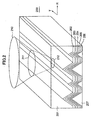
- Fig.2 shows a high density optical disk 200 having a substrate 201, an optical near field generation film 202, a protection film 203, a recording film 204, a protection film 205, a reflection film 206, and a protection film 207.
- the arrow R indicates a radial direction of the high density optical disk 200
- the arrow T indicates a tangential line direction in a case where the high density optical disk 200 is rotated.
- Tracks to which signals are recorded are consecutively formed in the tangential direction on the high density optical disk 200.
- the tracks form tapered protruding parts along the tangential direction.
- the protruding parts are shaped with the same linear form along the tangential direction, and are formed with prescribed inclinations in the radial direction, thereby forming a triangular peak at the tip portions.
- a laser beam 210, being incident on the substrate 201, forms a shape 211 on an incident plane on the substrate 201.
- the laser beam 210 being refracted at the substrate 201, is condensed on the tip portion of the optical near field film 202, thereby forming a laser spot 212 thereon.
- the optical near field film 202 may be formed, for example, as a thin film of metal (e.g. gold, silver, titanium, or aluminum), or of plastic or silicon in a case where a high sensitivity recording/reproduction material is used.
- the metal thin film may employ, for example, a material having the complex permittivity for which at least one of a real part or an imaginary part is a negative value for laser wavelength, a material having the complex permittivity for which a real part is a negative value and thus the absolute value of an imaginary part is smaller than that of the real part, or a material having the absolute value of the imaginary part of the complex refractive index which is larger than that of the real part of the complex refractive index.
- a conventional probe or the like for generating optical near field requires a hole to be drilled with, for example, an expensive focused ion beam (FIB), so as to form a fine aperture of a size no more than the wavelength of the laser beam for allowing the optical near field to pass therethrough.
- FIB focused ion beam
- the present invention requires no such fine aperture, or slit, to thereby achieve manufacture at low cost.
- the optical near field generation film 202 formed of thin metal material or the like may have a protection film 203 formed of, for example, silicon nitride (SiN) disposed at the opposite side of its incident surface. Further, the recording film 204 (TbFeCo), the protection film 205, and the reflection film 206 are formed therebelow. For example, a material with a high refractive index (e.g. ZnS/SiO 2 ) of approximately 2 may preferably be used for the optical near field generation film 202 in order to reduce cross-talk between adjacent tracks. Last, the protection film 207 is formed therebelow.
- a material with a high refractive index e.g. ZnS/SiO 2
- the distance between the optical near field generation probe and a recording medium is required to be controlled so that the optical near field is irradiated to a recording film of the recording medium while the recording medium is rotated.
- the conventional example faces the head/disk interface problem.
- the optical near field generation film 202 for intensifying the electric field is buried in the optical disk medium, the distance between the optical near field generation film 202 and the recording film 204 can be defined when forming the films in a process of optical disk manufacture.
- the distance between the optical near field generation film 202 and the recording film 204 be ⁇ /10 or less (however, 0 nm not included) for satisfactorily generating an optical near field. It is to be noted that if the optical near field generation film 202 is too thick, the optical near field cannot be generated since light is unable to be transmitted therethrough. Furthermore, by using a conventional sputtering apparatus or the like, the distance between the films can be precisely controlled in nanometer (nm) sizes.
- an optical near field can be generated in an area situated at a predetermined distance apart from the tip portion of the optical near field generation film 202 buried in the optical disk 120, thereby enabling the generated optical near field to be used for recording signals on the recording film 204 of the optical disk 120. Accordingly, the present invention has no difficulty in controlling the distance between the probe and the recording medium for generating the optical near field (head-disk interface problem).
- Fig.4 shows a model used for the calculation.
- like components are denoted by like reference numerals as of Fig.2.
- an FDTD method Finite Difference Time Domain Method
- the wavelength of the irradiated laser beam is 780 nm
- the numerical aperture (NA) of the objective lens is 0.8
- the diameter of the condensed beam is 0.95 ⁇ m (1/e2).
- the polarization of the laser beam is calculated as being TM polarization (P polarization) where the direction of the polarized laser beam is the radial direction of the optical disk.
- the track pitch is 500 nm.
- a metal thin film of gold having a thickness of 40 nm is used for the optical near field generation film 202, in which the refractive index is 0.175-i 4.91.
- the letter i indicates an imaginary part of complex permittivity.
- the angle of the apex of the triangles is 30 degrees.
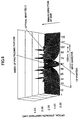
- Fig.5 shows the optical strength when calculating with the model in Fig.4.
- the electric field strength (light) is maximum in an area situated apart from the tip portion of the optical near field generation film 202 at a distance of 80 nm (40 nm from the border between the optical near field generation film 202 and the protection film 203). This area is the optical near field area.
- the calculation shows that the optical strength does not acutely decrease at the border between the optical near field generation film 202 and the protection film 203, and that the portion of maximum optical strength is situated in the optical near field area.
- the diameter of the condensed beam becomes 50 nm in the track direction, to thereby enable a fine recording in the track direction.
- the optical strength may become maximum at a portion immediately after the optical near field generation film 202.
- the protection film 203 may be formed immediately before the optical near field generation film 202.
- transmittance is 3% at the strength center in a case where a spherical wave is incident on a typical flat gold metal thin film with a thickness of 40 nm.
- transmittance is increased 43 times, thereby enabling high speed recording and high speed data transfer.
- the cross-talk with an adjacent track is -26 dB (1/20). Therefore, problems such as cross-talk, cross-erase, and cross-write do not occur.
- light use efficiency can be further improved.
- light use efficiency can also be further improved by adjusting, for example, the angle or height of the metal film.
- the tracks may be formed with varied (adjusted) height between the adjacent tracks.
- calculation of optical strength is performed using a medium with tracks of adjusted height such as the medium shown in Fig.2.
- the difference in the height of adjacent tracks is set to 0.65 ⁇ /n, in which n is the refractive index of the medium.
- Fig.6 shows the optical strength where a laser beam is condensed onto the tapered tip portions of the tracks (toward the side of the incident surface), wherein the track pitch is 250 nm.
- the cross-talk in the tracks situated toward the side of the incident surface is -26 dB (1/20). Therefore, problems such as cross-talk, cross-erase, and cross-write do not occur.
- the cross-talk in the tracks situated away from the side of the incident surface is also -26 dB (1/20). Therefore, problems such as cross-talk, cross-erase, and cross-write do not occur.
- the reason for such reduced cross-talk owes to the fact that a condensed beam being incident on the tapered tip portion of the metal film causes intensification of the electrical field and allows the strength of an incident wave to concentrate toward a center area, to thereby cause the beam diameter that was originally 0.95 ⁇ m (1/e 2 ) to be narrowed to approximately 0.5 ⁇ m (see Fig.6).
- the metal film shields the light irradiated to a side surface of a track or to an adjacent track.
- the metal film has a thickness that prevents heat from penetrating the protection film and reaching the recording film.
- the inclination angle of the tip portion for further reducing cross-talk, for example, forming the apex angle of the tip portion to an angle of no more than 90 degrees (however, 0 degrees not included), more specifically, to an angle between approximately 30 to 90 degrees.
- the inclined surfaces of the tapered protruding parts may be provided with different (varied) inclination angles among three or more tracks. By varying the angles, cross-talk can be further reduced. It is to be noted that the parameters used in this calculation are the same as those used in the calculation with the model of Fig.4.
- the calculated ⁇ /NA serving to define the beam diameter, is 0.975.
- the obtained ⁇ /NA would be 0.47, and a track pitch of 120 nm would be obtained.
- a high density recording medium with a track pitch that is several times narrower than the conventional track pitch can be obtained.
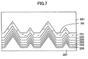
- Fig.7 shows a high density optical recording medium according to another embodiment of the present invention.
- the high density optical recording medium in the embodiment shown in Fig.7 serves to further reduce cross-talk between adjacent tracks.
- like components are denoted by like reference numerals as of Fig.2.
- the high density optical recording medium has a dielectric film 701 of high refractive index (higher than that of the protection layer or the substrate 201) disposed between the substrate 201 and the optical near field generation film 202, and a flat portion 702 interposed between the protruding parts.
- the dielectric film 701 is formed of, for example, ZnS having a refractive index of approximately 2.2.
- the dielectric film 701 serves to prevent the light conventionally diffused to tracks beside the target recording/reproduction track from diffusing to adjacent tracks by having the light bent by refractive index difference. It is to be noted that a track pitch of no more than 100 nm can be obtained in a case where the present invention is applied to a magnetic optical disk using magnetic super resolution, which can permit a relatively large amount of cross-talk. Furthermore, the high density optical recording medium according to the present invention can serve as a removable medium since the recording medium has no head/disk interface problem.
- a light-shielding member is disposed at a center portion of the condensing area and an optic super resolution lens for reducing optical strength at the center portion is employed, so that reproduction can be performed where the optical strength at the center portion of the beam spot on the reproduction/recording surface is lower than the portion surrounding the center portion.
- a method for optically reproducing information by using an optical super resolution lens is described in Japanese Laid-Open Patent Application No.7-6379.
- reproduction of information using optical super resolution can be achieved by disposing a light shielding plate between the ⁇ /2 plate and the condensing lens 113 (see Fig.1).
- Fig.8 shows a high density optical recording medium according to another embodiment of the present invention.
- the high density optical recording medium shown in Fig.8 has various tracks with different heights for adjacent tracks.
- adjacent tracks refer not only to tracks that are disposed on both sides of a target track, but also to a number of tracks disposed within a prescribed area.
- cross-talk between adjacent tracks can be reduced.
- the apex angle of the inclinations between adjacent tracks may also be adjusted (varied).
- Fig.9 shows a high density optical recording medium according to another embodiment of the present invention.
- like components are denoted by like reference numerals as of Fig.2.
- a tip portion of a track has a flat shape.
- the track is formed with a tapered tip portion, an optical near field can be generated where the tip portion of a track alternatively has a flat part 202-A.
- the length of the flat part d is no more than ⁇ /(2n) (however, 0 not included) where the wavelength of the laser beam is ⁇ , and where the refractive index of the optical near field generation film is n.
- Figs.10(a)-10(c) show a high density optical recording medium according to another embodiment of the present invention.
- like components are denoted by like reference numerals as of Fig.2.
- the side surface of the tracks are formed with curvatures.
- This recording medium having a side surface with no fixed inclination and a tip portion (apex portion) serving as an inflexion point, is also able to generate an optical near field.
- the tip portion of the track can be formed in a parabolic shape.
- a corner portion (where the tip portion is relatively flat) may be formed with a curvature.
- the high density optical recording medium may be obtained by providing a gap at a plastic substrate. Accordingly, the high density optical recording medium of the present invention can be obtained even with a material with a small refractive index.
- Fig.11 shows a high density optical recording medium according to another embodiment of the present invention.
- the high density optical recording medium of Fig.11 has plural layers of the optical near field generation film provided in the thickness direction of the recording medium, in which the layers are separated by separation layers 1111, 1112.
- like components are denoted by like reference numerals as of Fig.2.
- recording density of the recording medium can be enhanced in proportion to the number of layers.
- each layer of recording film 204 is a magnetic optical recording film. Recorded signals are read by using the magnetic field generated from the optical near field in each recording film 204.
- TbFeCo may be used as the recording film.
- This recording medium has little residual magnetization at room temperature, and hardly leaks any magnetic flux; however, magnetic signals can be detected with a magnetic head for reproduction since residual magnetization increases when a laser beam is condensed to a desired reproduction portion.
- a UV curable resin, a dielectric material, or an aluminum material for example, may be disposed as the separation layers 1111, 1112 interposed between each of the recording layers formed of the optical near field generation film 202, the protection film 203, and the recording film 204, to thereby prevent interference between the layers.
- Fig.12 shows a high density optical recording medium according to another embodiment of the present invention.
- the high density optical recording medium in the embodiment shown in Fig.12 has a structure similar to that of the embodiment shown in Fig.11 where plural layers including the optical near field generating film are provided; however, in the embodiment shown in Fig.12, the tracks are disposed at positions deviating from each other in the radial direction. With the arrangement of the embodiment of Fig.12, light-use efficiency can be effectively achieved. Nevertheless, the same as the embodiment shown in Fig.11, this embodiment also enables recording/reproduction of signals for each layer.
- the optical near field generation film may be formed with aluminum, in which the film is annealed with heat.
- aluminum By employing aluminum for the optical near field generation film, manufacturing cost can be reduced. Furthermore, since the use of aluminum enhances transmittance at the tip portion, light-use efficiency can be improved.
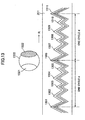
- Fig.13 shows a high density optical recording medium according to another embodiment of the present invention.
- the high density optical recording medium shown in Fig.13 is able to obtain radial push-pull signals as tracking signals.
- the arrow R shown in Fig.13 indicates a radial direction of the optical disk (track-crossing direction).
- a single cycle (track group) has a number (N) of tracks with protrusions of different height (for example, tracks 1301, 1302, 1303, 1304, and 1305 in Fig.13).
- tracks of the optical disk are formed by repeating the formation of the aforementioned track group in which tracks with heights corresponding to those of the aforementioned track group (for example, tracks 1306, 1307, 1308, 1309, and 1310) are formed in the radial direction of the optical disk.
- the distance between the track 1301 and the track 1306 is the distance of a single cycle d.
- numeral 1320 is a beam spot of a laser beam incident on the tracks
- numerals 1321 and 1322 are patterns of the beam spot formed from reflected light.
- the track of the optical disk is formed to satisfy a relation of ⁇ /d ⁇ 1, where ⁇ is the wavelength of the laser beam of the beam spot 1320, and d is the distance of a single cycle.
- ⁇ 1 (first) diffracted light is generated.
- the patterns of the beam spot of the diffracted light change according to the degree (amount) of displacement of the center of the incident beam spot 1320 with respect to the center of each track (for example, pattern 1321 or 1322 in Fig.13).
- the second photo detector 111 shown in Fig.1 detects the pattern changes of the diffracted light, and the degree (amount) of the displacement of the center of the incident beam spot 1320 with respect to the center of each track.
- the track control system 150 performs tracking control, in which the track actuator 151 is driven to adjust the position of the objective lens 105 shown in Fig.1 in the radial direction (track crossing direction).
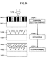
- Fig.14 illustrates a mastering process.
- a resist material 1402 e.g. photo resist or resist material employed for electron beam
- a substrate 1401 e.g. quartz
- Portions of the coated resist 1402 targeted for forming the tracks are exposed by using a laser mastering apparatus or an electron beam lithography apparatus, in which a laser beam or an electron beam is irradiated thereto via a lens 1410, to thereby form track patterns.
- a laser beam having a wavelength of 250 nm is typically employed for exposure of resist
- an electron beam may be employed depending on track pitch, such as a case of forming a narrow track pitch of no more than 100 nm.
- Step 2 the exposed resist material 1402 is developed, to thereby form tracks having tapered tip portions.
- the cross-sectional shapes of the tracks can be adjusted by controlling, for example, the resist or conditions of development.
- a stamper 1403 is formed by electroforming.
- a substrate is formed by injection molding, then, layers including, for example, an optical near field generation film, a protection film (e.g. SiN), and/or a recording film (e.g. TbTeCo) are formed as described with the high density optical recording medium according to the embodiments of the present invention, and then another protection film is formed, thereby obtaining a replication disk.
- This method can be performed by utilizing existing apparatuses and installations for manufacturing a stamper of an optical disk, thereby incurring little manufacturing cost.
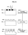
- Fig.15 shows a mastering process using an RIE (Reactive Ion Etching) technique.
- RIE reactive Ion Etching
- the tip portion has a pointed shape.
- the diameter of the mark to be recorded is determined according to how pointed the tip portion is.
- a resist material 1502 (e.g. photo resist or resist material employed for electron beam) is coated on a substrate 1501 (e.g. quartz). Portions of the coated resist 1502 targeted for forming the tracks are exposed by using a laser mastering apparatus or an electron beam lithography apparatus, in which a laser beam or an electron beam is irradiated thereto via a lens 1510, to thereby form track patterns. In a case of forming tracks with adjusted (varied) height, exposure is performed by altering the width of exposure patterns.
- Step 2 the exposed resist material 1502 is developed, and the resist corresponding to the target track portions is removed.
- Step 3 by using a dry etching technique such as the aforementioned RIE technique, tracks with tapered tip portions can be formed. Last, the remaining resist material is removed to form a stamper 1501.
- a substrate is formed by injection molding, and a replication disk is obtained in the same manner described with the embodiment shown in Fig.14.
- Fig.15 shows a mastering process using an RIE (Reactive Ion Etching) technique.
- RIE Reactive Ion Etching
- exposure is performed by altering the intensity of the laser beam or electron beam used for the exposure (Step 1).
- Step 2 in Fig.15 the resist 1502 remaining after the developing procedure can be formed having different thickness in correspondence with the height of the tracks.
- Step 3 by using a dry etching technique such as the aforementioned RIE technique, tracks with tapered tip portions can be formed.
- the remaining resist material 1502 is removed to form a stamper 1501.
- a substrate is formed by injection molding, and a replication disk is obtained in the same manner described with the embodiment shown in Fig.14.
- embossments are formed for recording addresses for recording/reproduction to a blank disk, for example, a ROM disk.
- the present invention does not form embossments for recording such addresses during a manufacturing process of an optical disk.
- a memory apparatus performs an initial formatting procedure where the memory apparatus records data to the disk with a typical data recording (optical recording or magneto optical recording) technique.
- a control part e.g. optical disk controller and microprocessor
- the control part performs recording control by using a low power beam for tracing tracks and a high power beam for sequentially recording the information in a predetermined portion at a predetermined clock timing.
- address information stored in a memory of the memory apparatus is read out when the control part of the memory apparatus receives a format command from a host apparatus, so that the control part performs recording control by using a low power beam for tracing tracks and a high power beam for sequentially recording the address information on a predetermined portion at a predetermined clock timing.
- the process of manufacturing a recording medium can be simplified.
- Fig.17 shows an example for modulating the magnetic field and laser pulse for a magnetic optical disk.
- Fig.17(A) shows a laser pulse irradiating during recording
- Fig.17(B) shows an external magnetic field corresponding to recording signals
- Fig.17(C) shows recording patterns formed on a recording medium.
- numeral 1703 is a pattern recorded when the external magnetic field is +H
- numeral 1704 is a pattern recorded when the external magnetic field is -H.
- the external magnetic field corresponds to the information that is to be recorded.
- the patterns shown in Fig.17(C) can be recorded on the recording medium.
- crescent moon shaped patterns as shown in Fig.17(C) can be recorded on the recording medium, to thereby attain high density in a tangential direction of a track (track direction).
- this modulating technique can be used for over-write recording, to thereby achieve faster recording and/or reproduction.
- Fig.18 shows an example of an optical head and a magnetic head in a case of recording/reproducing by using the example of the modulating magnetic field and laser pulse shown in Fig.17.
- an optical head 1802 includes, for example, a laser diode 1803, a collimator lens 1804, an objective lens 1805, and an actuator 1806 serving to move the objective lens 1805.
- the laser beam irradiated from the laser diode 1803 is converted to a parallel beam by the collimator lens 1804, and is condensed to the recording surface of an optical disk 1801 by the objective lens 1805.
- the focus control system 140 controls the position of the focal point of the condensed light by driving the actuator 1806 so as to condense the light beam onto the tip protruding portion of the tracks of the optical disk 1801.
- a floating slider 1810 including a recording coil 1811 and a reading head 1812 is disposed on the opposite side of the optical head 1802 where the optical disk 1801 is situated therebetween.
- the recording coil 1811 of the floating slider 1810 performs modulation of magnetic field, to thereby record data on the optical disk 1801.
- a recording magnetic head with, for example, GMR (Giant Magnetic Resistance) or TMR (Tunnel Magnetic Resistance) may be used.
- a spin-valve magnetic resistance head may be employed, as shown in Japanese Laid-Open Patent Application No.10-340430.
- a magnetic head including, for example, a first magnetic layer, an insulation layer, and a second magnetic layer may be employed, as shown in Japanese Laid-Open Patent Application No.2001-229515.
- Fig.19 shows another example of an optical head and a magnetic head in a case of recording/reproducing by using the example of a modulating magnetic field and laser pulse shown in Fig.17.
- an optical head 1802 includes, for example, a laser diode 1803, a collimator lens 1804, an objective lens 1805, and an actuator 1806 serving to move the objective lens.
- NA numerical aperture
- a floating slider 1810 including an air-core recording coil 1811, a reading head 1812, and a lens 1813 in the air-core is disposed on the same side of the optical head 1802 with respect to the optical disk 1801.
- a magnetic field modulation magnetic head may be disposed on the side where light is incident on the medium, and an optical head may be used for reproduction.
- Fig.20 shows a substrate of a high density recording medium (optical disk) used in a case where an optical head has a small numerical aperture (NA), as in the example described in Fig.18.
- a high density recording medium used for a case where an optical head has a small numerical aperture (NA) can be formed by stacking films onto a substrate 2001 in an order of an optical near field generation film, a protection film, and a recording film.
- Fig.21 shows a substrate of a high density recording medium (optical disk) used in a case where an optical head has a large numerical aperture (NA), as in the example described in Fig.19.
- a high density recording medium used for a case where an optical head has a large numerical aperture (NA) can be formed by stacking films onto a substrate 2101 in an order of a recording film, a protection film, and an optical near field generation film.
- a device having a protruding shape e.g. cantilever
- a protruding shape e.g. cantilever
- a resist material may be disposed on a quartz substrate, and the resist can be exposed to form exposure patterns thereto. Then, after the exposed resist material is developed, the resist remaining at portions where tracks are to be formed are removed. Next, a dry etching technique such as an RIE technique is applied to form tracks having tapered tip portions. Last, a stamper is formed by removal of the remaining resist material. After the stamper is formed, a substrate for a replication disk is formed by injection molding, and with the above-described procedures, a replication disk is obtained.
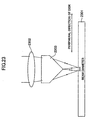
- Fig.22 shows an example of attaining high density in a tangential direction (scanning direction of a beam spot) of a track by using a cylindrical lens 2202.
- the cylindrical lens 2202 being held by a suspension part 2203, is disposed on the incident surface of an optical disk 2201.
- the laser beam 2204 incident on the cylindrical lens 2202 becomes a compressed oval spot in a tangential direction (scanning direction of a beam spot) of a track, in which the spot diameter in the tangential direction of the track is shortened. Accordingly, high density in the tangential direction of the track can be attained.
- the density can be further increased.
- an axicon prism 2303 (having an axicon shape only in a tangential direction of an optical disk 2301) between an optical disk 2301 and an objective lens 2302, high density can be attained in a peripheral direction of a track.
- signals can be recording with a fine beam (having a distribution of a 0 Bessel function). Accordingly, high density can be attained in a tangential direction of a track.
- the present invention provides a high density optical recording medium, a memory apparatus, a method of recording/reproducing a high density optical recording medium, and a method of manufacturing a high density optical recording medium.
Landscapes
- Physics & Mathematics (AREA)
- Optics & Photonics (AREA)
- Electromagnetism (AREA)
- Engineering & Computer Science (AREA)
- Manufacturing & Machinery (AREA)
- Optical Head (AREA)
- Optical Recording Or Reproduction (AREA)
- Optical Record Carriers And Manufacture Thereof (AREA)
Abstract
It is an object of the present invention
to provide a high density optical disk apparatus and
the like that uses optical near field without
causing a head/disk interface problem. In order to
achieve the object, the present invention provides
an optical recording medium having at least a
recording film and a protection film disposed on a
substrate, wherein a plurality of recording tracks
having tapered protruding portions are disposed,
along a predetermined direction, on a signal
recording surface to which a laser beam is incident,
wherein the protruding portions are formed to
include an optical near field generation film.
Accordingly, an optical near field generation film
for intensifying electric field can be buried in an
optical disk medium, and the head/disk interface
problem can be prevented from occurring.
Description
The present invention generally relates to
an optical recording medium, a memory apparatus, and
a recording/reproduction method, more particularly,
a high density optical recording medium, a memory
apparatus, and a recording/reproduction method that
use optical near field.
In a conventional optical head for an
optical disk, light is condensed by using a lens.
In this case, the amount of information that can be
recorded onto the optical disk depends on the
diameter of the condensed beam. The diameter of
such condensed beam is confined to the wavelength of
the laser beam for recording and/or reproducing
information to/from the optical disk, and by the
numerical aperture (NA) of the optical lens system.
In order to obtain a high density optical disk, it
is required to shorten the wavelength of the laser
beam and to increase the numerical aperture of the
optical lens. Nevertheless, due to limits in
diffraction, there are limits in obtaining such high
density optical disks with such methods.
In order to increase the numerical
aperture of the optical lens system, a method for
recording information onto an optical disk medium is
proposed, in which a numerical aperture (NA) of 1 or
more is obtained by employing a SIL (Solid Immersion
Lens) and utilizing the evanescent light leaking
from the bottom of the SIL. Nevertheless, recording
information onto the optical disk medium by
utilizing the evanescent light requires the distance
between the SIL and the recording surface of the
optical disk to be maintained at no more than 1/10
of the wavelength. Therefore, precise control is
required for maintaining a constant distance between
the optical disk and the SIL. There is also a
problem where dust may adhere to the optical disk to
cause contact with the SIL. The problem of dust
causes difficulty in attaining removability, which
is one of the benefits of the optical disk.
Furthermore, there are limits in obtaining a high
density optical disk by employing the SIL since the
numerical aperture (NA) is increased based on the
refractive index of the SIL.
Meanwhile, a method for recording and/or
reproducing information to/from an optical disk is
proposed, in which an optical near field is used for
increasing capacity of an optical disk by
intensifying the density of the optical disk.
As for a widely used optical near field
probe serving to generate the optical near field,
there is an optical fiber (optical fiber probe)
having a sharpened tip with a fine opening of a size
no more than the wavelength of the laser beam used
for recording and/or recording. The optical fiber
probe is manufactured by applying metal coating to
portions other than its tip portion after heating
and stretching an end of an optical fiber or after
tapering an optical fiber with a chemical etching
method. Accordingly, by directing an incident laser
beam on the optical fiber probe, an optical near
field can be generated at the proximity of the fine
opening formed at the tip portion.
Nevertheless, the optical fiber probe has
a drawback of inefficient utilization of light. For
example, in a case where the aperture diameter is
100 nm, the ratio of the optical strength of the
incident laser beam on the optical fiber probe to
the laser beam emitted from the tip portion of the
optical fiber probe becomes 0.001% or less, thereby
resulting to an emitted laser beam with considerably
low optical strength. In order to solve this
problem, the below-given optical near field probes
are proposed.
The first probe is a multi-level taper
optical fiber probe. This optical fiber probe is
described in "Applied Physics Letters" (Vol.68,
No.19, p. 2612-2614) issued in 1996, and "Applied
Physics Letters" (Vol.73, No.15, p. 2090-2092)
issued in 1998. This optical fiber probe has its
pointed tip formed in two or three varying levels
from its root portion to its tip portion.
The next probe is a metal needle probe.
This probe is described in Japanese Laid-Open Patent
Application No.6-137847, in which light is
irradiated to a tip of a needle for generating an
optical near field in proximity to the tip portion.
The next probe is a fine aperture fiber
probe with a fine metal sphere. This fiber probe is
described in Japanese Laid-Open Patent Application
No.11-101809, in which a fine metal sphere is formed
at a center of a fine aperture of a tip portion of
the fiber probe. In this fiber probe, an optical
near field is generated by irradiating light from
the fine aperture and thereby exciting plasmon in
the fine metal sphere.
The next probe is a probe with a metal
coated glass segment. This probe is described in
"Physical Review B" (Vol.55, No.12, p.7977-7984)
issued in 1997. This probe has a metal film with a
thickness of approximately 50 nm formed on a
triangularly cut-out glass segment, in which surface
plasmon is excited on the metal film. Accordingly,
since the excited surface plasmon is propagated
toward the tip of the probe, a strong optical near
field is generated in proximity to the tip.
The next probe is a glass substrate probe
with a metal scatterer. This probe is described in
Japanese Laid-Open Patent Application No.11-250460
This is a probe having a metal scatterer attached to
a bottom portion of a glass substrate. By attaching
the metal scatterer, a strong optical near field is
generated in proximity to the metal scatterer.
In near field optics, it is necessary to
maintain a space of approximately a few nanometers
(nm) to several tens of nanometers between an
optical near field generating member and the
recording surface. Accordingly, in the above-described
probes formed with the optical fiber or
the glass segment, a particular control system is
necessary for precisely controlling the space
between the tip portion of the probe and the
recording surface. This control system, in general,
measures the space between the tip portion of the
probe and the recording surface by measuring the
atomic force between the tip portion of the probe
and the recording surface, and servo controls the
position of the probe so that the measured value is
constant. Nevertheless, since there is a certain
limit to the servo control area, the relative
scanning speed of the probe with respect to a
recording medium is to be no more than a prescribed
speed with an error no more than a prescribed value.
Particularly, in an optical disk memory device
required to provide high speed data transfer, it is
necessary to increase the speed at which the probe
can scan the optical disk. Nevertheless, in a case
where a disk having tilt or skew is rotated at high
speed, the servo control system may be unable to
provide sufficient control since the probe is
required to trace large disturbances with high
frequency amplitude. In order to solve the problem,
the below described probe is proposed.
The first probe is a flat aperture optic
fiber probe. This optical fiber probe is described
in "Electronics and Communications in Japan" (Part 2,
Vol.81, No.8, p.41-48) issued in 1998 (translated
from "Journal of The Institute of Electronics,
Information, and Communication Engineers Vol.J81-C-I,
No.3, p.119-126). This probe has an aperture formed
by applying an anisotropic etching technique to a
silicon substrate. Since the portion surrounding
the aperture is flat, the distance between the tip
portion of the probe and the recording surface can
be maintained constant when the probe approaches the
recording medium.
The next probe is a pad aperture probe.
This probe is described in Japanese Laid-Open Patent
Application No.11-265520. This probe has a
quadrangular pyramid-shaped protrusion with a fine
aperture formed at a tip portion thereof, and also
has a pad formed at a surrounding portion of the
protrusion. The pad serves to maintain the distance
between the tip portion of the probe and the
recording surface constant.
The next probe is a plane illumination
laser probe with a fine metal chip. This probe is
described in "Applied Physics" (Vol.68, No.12,
p.1380-1383) issued in 1999. This probe has a fine
metal protrusion with a fine aperture formed at an
end face of the plane illumination laser port.
Since the probe has a flat structure, the distance
between the tip portion of the probe and the
recording surface can be maintained constant when
the probe approaches the recording medium.
The next probe is described in "Optics
Communications" (Vol.69, Nos.3 and 4, p.219-224)
issued in 1989. This probe is designed to
efficiently generate a slight optical near field.
This probe efficiently generates the optical near
field by applying light to a patch antenna and a
coaxial cable.
Another probe is described in U.S. Patent
No.5,696,372 issued on December 9, 1997 (Grober et
al.). This probe is also aimed at efficiently
generating a slight optical near field. This probe
employs a fine dipole antenna formed with a bow-tie
shaped metal segment for generating a slight optical
near field.
With a system for recording and/or
reproducing information by using an optical near
field, the three below given factors are required to
be satisfied. First, it is required to precisely
control the distance between the optical near field
probe or the like serving to generate the optical
near field and the recording medium to be a constant
distance shorter than the wavelength of the laser
beam used for recording/reproducing information.
Second, the beam spot of the generated optical near
field is required to be of a fine size. Third, the
generated optical near field is required to be of
high light use efficiency.
The above-described multi-stage pointed
optical fiber probe has a light use efficiency which
is approximately 10 to 100 times higher than that of
a typically used fiber probe, but is still
insufficient to be applied for optical
recording/reproduction, which requires a high light
use efficiency of 10% or more. In addition, it is
mechanically fragile, and is especially vulnerable
in high speed scanning since optical fiber is used.
All of the metal needle probe, the fine
aperture fiber probe with a fine metal sphere, the
probe with a metal coated glass segment, and the
glass substrate probe with a metal scatterer are
able to attain high light use efficiency by
utilizing their metal property. All of them,
however, are formed with a mechanically fragile tip,
and are, therefore, particularly vulnerable in high
speed scanning. Particularly, the metal pin probe
and the glass substrate probe with a metal scatterer
have a problem in that a large amount of background
light is detected therefrom since the light that is
irradiated neither to the tip of the needle nor the
scatterer becomes incident on the recording medium.
Furthermore, as described above, some
other probes capable of providing high speed
scanning are also proposed. Although the flat
aperture probe and the pad aperture probe can be
used in high speed scanning, their light use
efficiency is low.
The plane illumination laser probe with a
fine metal chip is expected to provide high speed
scanning performance, high light use efficiency, and
little background light. In generating a strong
optical near field by using the metal fine
protrusion of the probe, the form of the metal is to
be optimized. Nevertheless, neither the form nor
the method of manufacture is disclosed.
With the probe for efficiently generating
an optical near field by applying light to a patch
antenna and a coaxial cable, or with the probe
employing a fine dipole antenna formed with a bow-tie
shaped metal segment for generating a slight
optical near field, there still is a problem with
dust on the recording medium, and a problem in
precisely controlling the distance between the
optical near field generating member and the
recording medium to a constant minute distance that
is shorter than the wavelength of the laser beam
used for recording/reproduction (head/disk interface
problem). It is, therefore, difficult to attain
removability, which is one of the advantages of an
optical disk.
Meanwhile, a method where a lens-like
substrate is disposed in an optical disk medium for
improving recording density is disclosed in "Optical
Data Storage 2001 Technical Digest of 2001, April
22-25, (p.277-279, Guerra et al.). This method is
aimed at solving the dust problem and the head/disk
interface problem. However, this method does not
use an optical near field, but uses light condensed
by a micro-lens installed in a recording medium for
recording/reproducing with the recording medium.
This enables recording density to be increased by
increasing the refractive index of the material of
the lens. Nevertheless, as described in the
document, the track pitch can merely be reduced to
approximately one half when using a typical optical
system since there are limits to the refractive
index. As a result, its recording density can only
be enhanced to approximately two times. Furthermore,
manufacture of the recording medium is difficult
since the recording medium requires a spherical
lens-shaped substrate to be uniform at its periphery.
Furthermore, the track pitch can only be narrowed to
a small degree, and recording density cannot be
largely increased since it is possible that the beam
may diffuse to an adjacent track and cause problems
such as cross-talk, cross-erase, and cross-write.
In addition, the lens uses, for example, TiO2 as its
material since a refractive index of 2.7 is required.
With such material, however, light cannot pass
through in a case of employing a blue-violet laser
diode (LD) with a wavelength of 410 nm. Accordingly,
the method cannot be applied to a short wavelength
laser diode, and cannot attain high recording
density.
The present invention aims to provide a
high density optical recording medium, a memory
apparatus, a high density recording/reproduction
method, and a manufacturing method of a high density
optical recording medium that obviate the problems
caused by the related art.
It is an object of the present invention
to provide a high density optical recording medium,
a memory apparatus thereof, and a
recording/reproduction thereof that satisfy the
above-described three conditions with an information
recording/reproduction system using optical near
field.
In order to achieve the object, the
present invention provides an optical recording
medium having at least a recording film and a
protection film disposed on a substrate, the optical
recording medium including: a plurality of recording
tracks being disposed, along a predetermined
direction, on a signal recording surface to which a
laser beam is incident, the recording tracks having
tapered protruding portions; wherein the protruding
portions are formed of an optical near field
generation film.
Accordingly, an optical near field
generation film for intensifying electric field can
be buried in the optical disk medium, and the
distance between the optical near field generation
film and the recording film can be defined when
forming the films in a process of optical disk
manufacture. Furthermore, by using a conventional
sputtering apparatus or the like, the distance
between the films can be precisely controlled in
nanometer (nm) sizes. Accordingly, as long as a
laser beam is controlled to condense at the tip
portion of the optical near field generation film by
using an optical system of a typical optical disk
apparatus, an optical near field can be generated in
an area situated at a predetermined distance apart
from the tip portion of the optical near field
generation film buried in the optical disk, thereby
enabling the generated optical near field to be used
for recording signals on the recording film.
Accordingly, the present invention is free from the
head/disk interface problem that requires the
distance between the probe and the recording medium
to be precisely controlled to the distance for
generating the optical near field.
Other objects, features and advantages of
the present invention will be set forth in the
description which follows, and in part will become
apparent from the description and the accompanying
drawings.
In the following, embodiments of the
present invention are described with reference to
the accompanying drawings.
Fig.1 is a schematic view showing an
apparatus 100 for recording signals to an optical
disk and/or reproducing signals recorded to an
optical disk according to an embodiment of the
present invention. Although a magnetic optical
recording technique is applied in this embodiment,
other techniques, such as, a phase change technique,
may alternatively be applied to the present
invention.
In Fig.1, an optical system of a head for
a magnetic optical disk is shown, in which a
recording/reproduction apparatus 100 mainly includes,
for example, a recording/reproduction optical system
including a semiconductor laser 101 (laser diode), a
collimator lens 102, a beam shaping prism 103, a
first polarization beam splitter 104, an objective
lens 105, a second polarization beam splitter 106, a
condensing lens 107, a half-prism 108, a knife-edge
109, a first photo detector 110, a second photo
detector 111, a λ/2 plate 112, a condensing lens
113, a third polarization beam splitter 114, a third
photo detector 115, and a fourth photo detector 116;
a recording system 122 for driving the semiconductor
laser 101 from an input of data 121; a reproduction
system 130 for reproducing a reproduction signal 131
from the outputs of the third photo detector 115 and
the fourth photo detector 116; a focus control
system 140 for performing focus control based on
output of the first photo detector 110; a focus
actuator 141 driven by the focus control system 140;
a tracking control system 150 for performing
tracking control based on output of the second photo
detector 111; and a track actuator 151 driven by the
tracking control system 150.
In recording the data 121 onto an optical
disk 120, the data 121 is input to the recording
system 122, and the recording system 122 drives the
laser diode 101 according to the input data 121. In
reading out data recorded to the optical disk 121,
the laser diode 101 outputs light having an optical
strength for reproduction.
The laser light beam emitted from the
semiconductor laser 101 is converted to a parallel
beam by the collimator lens 102. After passing the
beam shaping prism 103, the beam is converted to a
linear polarized light in a direction perpendicular
to the scanning direction of the optical disk 120
(P-polarized light) by the first polarization beam
splitter 104 for obtaining satisfactory
recording/reproduction performance with the magnetic
optical technique, and is directed to the objective
lens 105, thereby being condensed onto the optical
disk 120 by the objective lens 105. Here, in a case
where signals are recorded on the optical disk 120,
the polarization angle of reflected light rotates
owing to the Kerr effect. That is, in a case where
signals are recorded, a P component light for signal
detection is rotated for a rotation angle of K
owing to the Kerr effect, to thereby generate an S
component light. The reflected light of P and S
components passes through the second polarization
beam splitter 106, the λ/2 plate 112, the
condensing lens 113, and is separated to P component
light and S component light by the third
polarization beam splitter 114. The separated P
component light and the S component light are
incident on the third photo detector 115 and the
fourth photo detector 116, respectively. The
reproduction system 130 calculates the difference of
optical strength between the P component light and
the S component light according to the difference in
the output between the third photo detector 115 and
the fourth photo detector 116, to thereby detect the
signals recorded on the optical disk 120, and output
the signals as reproduction signals 131.
Meanwhile, a part of the light reflected
from the optical disk 120 is separated by the second
polarization beam splitter 106, and is incident on
the knife-edge 109 after passing through the
condensing lens 107 and the half-prism 108. The
amount of light incident on the first photo detector
110 via the knife-edge 109 changes depending on the
amount of deviation of the focal point of the laser
beam condensed on the optical disk 120. The focus
control system 140 detects focus error signals by
detecting the changes in the amount of light
incident on the first photo detector 110. Then, in
accordance with the focus error signals, the focus
control system 140 drives the focus actuator 141,
and controls the position of the objective lens 105
for condensing the laser beam on the optical disk
120.
Meanwhile, a part of the light separated
by the half-prism 108 is incident on the second
photo detector 111 for generating tracking error
signals. According to the generated tracking error
signals, the tracking control system 150 drives the
tracking actuator 151 and moves the objective lens
105 in a radial direction of the optical disk 120
for enabling the laser beam spot to trace the track
having signals recorded thereto.
With such an optical disk apparatus, the
distance between the optical disk medium and a tip
portion of the optical head is on the order of
several 100 µm to several mm. By using the
advantage of the distance, the optical disk medium
may serve as a removable, inexpensive and highly
reliable recording medium for wide use. Next, an
exemplary high density optical recording medium
according to the present invention is described with
reference to Fig.2. Fig.2 shows a high density
optical disk 200 having a substrate 201, an optical
near field generation film 202, a protection film
203, a recording film 204, a protection film 205, a
reflection film 206, and a protection film 207. In
Fig.2, the arrow R indicates a radial direction of
the high density optical disk 200, and the arrow T
indicates a tangential line direction in a case
where the high density optical disk 200 is rotated.
Tracks to which signals are recorded are
consecutively formed in the tangential direction on
the high density optical disk 200. The tracks form
tapered protruding parts along the tangential
direction. The protruding parts are shaped with the
same linear form along the tangential direction, and
are formed with prescribed inclinations in the
radial direction, thereby forming a triangular peak
at the tip portions. A laser beam 210, being
incident on the substrate 201, forms a shape 211 on
an incident plane on the substrate 201. Further,
the laser beam 210, being refracted at the substrate
201, is condensed on the tip portion of the optical
near field film 202, thereby forming a laser spot
212 thereon. The optical near field film 202 may be
formed, for example, as a thin film of metal (e.g.
gold, silver, titanium, or aluminum), or of plastic
or silicon in a case where a high sensitivity
recording/reproduction material is used. The metal
thin film may employ, for example, a material having
the complex permittivity for which at least one of a
real part or an imaginary part is a negative value
for laser wavelength, a material having the complex
permittivity for which a real part is a negative
value and thus the absolute value of an imaginary
part is smaller than that of the real part, or a
material having the absolute value of the imaginary
part of the complex refractive index which is larger
than that of the real part of the complex refractive
index. A conventional probe or the like for
generating optical near field requires a hole to be
drilled with, for example, an expensive focused ion
beam (FIB), so as to form a fine aperture of a size
no more than the wavelength of the laser beam for
allowing the optical near field to pass therethrough.
The present invention, however, requires no such
fine aperture, or slit, to thereby achieve
manufacture at low cost.
Next, the optical near field generation
film 202 formed of thin metal material or the like
may have a protection film 203 formed of, for
example, silicon nitride (SiN) disposed at the
opposite side of its incident surface. Further, the
recording film 204 (TbFeCo), the protection film 205,
and the reflection film 206 are formed therebelow.
For example, a material with a high refractive index
(e.g. ZnS/SiO2) of approximately 2 may preferably be
used for the optical near field generation film 202
in order to reduce cross-talk between adjacent
tracks. Last, the protection film 207 is formed
therebelow.
Next, a principle of the present invention
is described with reference to Fig.3. In Fig.3,
like components are denoted by like reference
numerals as of Fig.2.
With an objective lens used for a typical
optical disk apparatus as described in Fig.1, it is
found that, according to calculation, when a laser
beam is irradiated to the tip portion of the optical
near field generation film 202 from the side of the
substrate 201 in a condensing manner, the electric
field (light) is intensified at a portion beneath
the optical near field generation film 202 where the
laser beam has transmitted therethrough.
Furthermore, it is found that the optical strength of the laser beam is maximum at an area (near field area) located at a predetermined distance from the optical nearfield generation film 202, and that the
optical strength rapidly decreases when further
apart from the near field area. This results from
the property of the optical near field. In a
conventional example of generating an optical near
field by using a probe for generating the optical
near field, the distance between the optical near
field generation probe and a recording medium
(optical disk) is required to be controlled so that
the optical near field is irradiated to a recording
film of the recording medium while the recording
medium is rotated. As described above, the
conventional example faces the head/disk interface
problem. With the present invention, however, since
the optical near field generation film 202 for
intensifying the electric field is buried in the
optical disk medium, the distance between the
optical near field generation film 202 and the
recording film 204 can be defined when forming the
films in a process of optical disk manufacture. For
example, in a case where the wavelength of the laser
beam incident on the signal recording surface is
indicated as λ, it is preferable that the distance
between the optical near field generation film 202
and the recording film 204 be λ/10 or less (however,
0 nm not included) for satisfactorily generating an
optical near field. It is to be noted that if the
optical near field generation film 202 is too thick,
the optical near field cannot be generated since
light is unable to be transmitted therethrough.
Furthermore, by using a conventional sputtering
apparatus or the like, the distance between the
films can be precisely controlled in nanometer (nm)
sizes. Accordingly, as long as a laser beam is
controlled to condense at the tip portion of the
optical near field generation film 202 by using an
optical system of a typical optical disk apparatus,
an optical near field can be generated in an area
situated at a predetermined distance apart from the
tip portion of the optical near field generation
film 202 buried in the optical disk 120, thereby
enabling the generated optical near field to be used
for recording signals on the recording film 204 of
the optical disk 120. Accordingly, the present
invention has no difficulty in controlling the
distance between the probe and the recording medium
for generating the optical near field (head-disk
interface problem).
Furthermore, it is found that the optical strength of the laser beam is maximum at an area (near field area) located at a predetermined distance from the optical near
Next, a calculation result in intensifying
electric field (light) is described. Fig.4 shows a
model used for the calculation. In Fig.4, like
components are denoted by like reference numerals as
of Fig.2. In calculating the intensification of
electric field, an FDTD method (Finite Difference
Time Domain Method) is applied to the model shown in
Fig.4. Here, the wavelength of the irradiated laser
beam is 780 nm, the numerical aperture (NA) of the
objective lens is 0.8, and the diameter of the
condensed beam is 0.95 µm (1/e2). Further, the
polarization of the laser beam is calculated as
being TM polarization (P polarization) where the
direction of the polarized laser beam is the radial
direction of the optical disk. Further, the track
pitch is 500 nm. Further, a metal thin film of gold
having a thickness of 40 nm is used for the optical
near field generation film 202, in which the
refractive index is 0.175-i 4.91. Here, the letter
i indicates an imaginary part of complex
permittivity. Further, the angle of the apex of the
triangles is 30 degrees.
Fig.5 shows the optical strength when
calculating with the model in Fig.4. As shown in
Fig.5, the electric field strength (light) is
maximum in an area situated apart from the tip
portion of the optical near field generation film
202 at a distance of 80 nm (40 nm from the border
between the optical near field generation film 202
and the protection film 203). This area is the
optical near field area. The calculation shows that
the optical strength does not acutely decrease at
the border between the optical near field generation
film 202 and the protection film 203, and that the
portion of maximum optical strength is situated in
the optical near field area. In the calculation,
the diameter of the condensed beam becomes 50 nm in
the track direction, to thereby enable a fine
recording in the track direction. According to
configuration, the optical strength may become
maximum at a portion immediately after the optical
near field generation film 202. For such a case,
the protection film 203 may be formed immediately
before the optical near field generation film 202.
It is to be noted that transmittance is 3%
at the strength center in a case where a spherical
wave is incident on a typical flat gold metal thin
film with a thickness of 40 nm. However, in a case
of using a tapered metal thin metal film, being
mainly composed of gold (Au) and having the
thickness shown in Fig.4, transmittance is increased
43 times, thereby enabling high speed recording and
high speed data transfer. In this example, the
cross-talk with an adjacent track is -26 dB (1/20).
Therefore, problems such as cross-talk, cross-erase,
and cross-write do not occur.
Accordingly, since a fine beam surpassing
the limits of diffraction can be generated by using
the optical near field, recording and/or
reproduction of signals can be performed with high
optical strength and with little cross-talk.
By optimizing the wavelength of the laser
by utilizing the phenomenon of plasmon resonance of
free electrons of metal, or optimizing track pitch,
light use efficiency can be further improved.
Moreover, light use efficiency can also be further
improved by adjusting, for example, the angle or
height of the metal film.
In order to narrow the pitch between the
tracks for increasing density, the tracks may be
formed with varied (adjusted) height between the
adjacent tracks. Here, calculation of optical
strength is performed using a medium with tracks of
adjusted height such as the medium shown in Fig.2.
In this case, the difference in the height of
adjacent tracks is set to 0.65 λ/n, in which n is
the refractive index of the medium. Thereby, cross-talk
between adjacent tracks can be sufficiently
reduced even if track pitch is narrowed. Fig.6
shows the optical strength where a laser beam is
condensed onto the tapered tip portions of the
tracks (toward the side of the incident surface),
wherein the track pitch is 250 nm. The cross-talk
in the tracks situated toward the side of the
incident surface (so-called land portion) is -26 dB
(1/20). Therefore, problems such as cross-talk,
cross-erase, and cross-write do not occur. In
addition, the cross-talk in the tracks situated away
from the side of the incident surface (so-called
groove portion) is also -26 dB (1/20). Therefore,
problems such as cross-talk, cross-erase, and cross-write
do not occur.
The reason for such reduced cross-talk
owes to the fact that a condensed beam being
incident on the tapered tip portion of the metal
film causes intensification of the electrical field
and allows the strength of an incident wave to
concentrate toward a center area, to thereby cause
the beam diameter that was originally 0.95 µm
(1/e2) to be narrowed to approximately 0.5 µm (see
Fig.6). Furthermore, the metal film shields the
light irradiated to a side surface of a track or to
an adjacent track. In addition, the metal film has
a thickness that prevents heat from penetrating the
protection film and reaching the recording film. It
is preferable to optimize the inclination angle of
the tip portion for further reducing cross-talk, for
example, forming the apex angle of the tip portion
to an angle of no more than 90 degrees (however, 0
degrees not included), more specifically, to an
angle between approximately 30 to 90 degrees.
Furthermore, the inclined surfaces of the
tapered protruding parts may be provided with
different (varied) inclination angles among three or
more tracks. By varying the angles, cross-talk can
be further reduced. It is to be noted that the
parameters used in this calculation are the same as
those used in the calculation with the model of
Fig.4.
In this example, the calculated λ/NA,
serving to define the beam diameter, is 0.975. In a
case supposing that a blue-violet laser diode with a
wavelength (λ) of 400 nm and an objective lens with
a numerical aperture (NA) of 0.85 are used, the
obtained λ/NA would be 0.47, and a track pitch of
120 nm would be obtained. Thereby, a high density
recording medium with a track pitch that is several
times narrower than the conventional track pitch can
be obtained.
Fig.7 shows a high density optical
recording medium according to another embodiment of
the present invention. The high density optical
recording medium in the embodiment shown in Fig.7
serves to further reduce cross-talk between adjacent
tracks. In the embodiment shown in Fig.7, like
components are denoted by like reference numerals as
of Fig.2. The high density optical recording medium
has a dielectric film 701 of high refractive index
(higher than that of the protection layer or the
substrate 201) disposed between the substrate 201
and the optical near field generation film 202, and
a flat portion 702 interposed between the protruding
parts. The dielectric film 701 is formed of, for
example, ZnS having a refractive index of
approximately 2.2. The dielectric film 701 serves
to prevent the light conventionally diffused to
tracks beside the target recording/reproduction
track from diffusing to adjacent tracks by having
the light bent by refractive index difference. It
is to be noted that a track pitch of no more than
100 nm can be obtained in a case where the present
invention is applied to a magnetic optical disk
using magnetic super resolution, which can permit a
relatively large amount of cross-talk. Furthermore,
the high density optical recording medium according
to the present invention can serve as a removable
medium since the recording medium has no head/disk
interface problem. In a case of reproduction using
an optical super resolution method, a light-shielding
member is disposed at a center portion of
the condensing area and an optic super resolution
lens for reducing optical strength at the center
portion is employed, so that reproduction can be
performed where the optical strength at the center
portion of the beam spot on the
reproduction/recording surface is lower than the
portion surrounding the center portion.
A method for optically reproducing
information by using an optical super resolution
lens is described in Japanese Laid-Open Patent
Application No.7-6379. In accordance with the
method described in Japanese Laid-Open Patent
Application No.7-6379, reproduction of information
using optical super resolution can be achieved by
disposing a light shielding plate between the λ/2
plate and the condensing lens 113 (see Fig.1).
Fig.8 shows a high density optical
recording medium according to another embodiment of
the present invention. In the embodiment shown in
Fig.8, like components are denoted by like reference
numerals as of Fig.2. The high density optical
recording medium shown in Fig.8 has various tracks
with different heights for adjacent tracks.
In this case, adjacent tracks refer not only to
tracks that are disposed on both sides of a target
track, but also to a number of tracks disposed
within a prescribed area. By adjusting (varying)
the height of the adjacent tracks, cross-talk
between adjacent tracks can be reduced. In this
case, the apex angle of the inclinations between
adjacent tracks may also be adjusted (varied).
Fig.9 shows a high density optical
recording medium according to another embodiment of
the present invention. In the embodiment shown in
Fig.9, like components are denoted by like reference
numerals as of Fig.2. In the high density optical
recording medium shown in Fig.9, a tip portion of a
track has a flat shape. Although the track is
formed with a tapered tip portion, an optical near
field can be generated where the tip portion of a
track alternatively has a flat part 202-A. It is,
however, preferable for the length of the flat part
d to be no more than λ/(2n) (however, 0 not
included) where the wavelength of the laser beam is
λ, and where the refractive index of the optical
near field generation film is n.
Figs.10(a)-10(c) show a high density
optical recording medium according to another
embodiment of the present invention. In the
embodiment shown in Figs.10(a)-10(c), like
components are denoted by like reference numerals as
of Fig.2. In the high density optical recording
medium of this embodiment, the side surface of the
tracks are formed with curvatures. This recording
medium, having a side surface with no fixed
inclination and a tip portion (apex portion) serving
as an inflexion point, is also able to generate an
optical near field. As shown in Fig.10(b), the tip
portion of the track can be formed in a parabolic
shape. Alternatively, as shown in Fig.10(c), a
corner portion (where the tip portion is relatively
flat) may be formed with a curvature. Further, the
high density optical recording medium may be
obtained by providing a gap at a plastic substrate.
Accordingly, the high density optical recording
medium of the present invention can be obtained even
with a material with a small refractive index.
Fig.11 shows a high density optical
recording medium according to another embodiment of
the present invention. The high density optical
recording medium of Fig.11 has plural layers of the
optical near field generation film provided in the
thickness direction of the recording medium, in
which the layers are separated by separation layers
1111, 1112. In the embodiment shown in Fig.11, like
components are denoted by like reference numerals as
of Fig.2. In this embodiment, recording density
of the recording medium can be enhanced in
proportion to the number of layers. For example,
each layer of recording film 204 is a magnetic
optical recording film. Recorded signals are read
by using the magnetic field generated from the
optical near field in each recording film 204. For
example, as described in the Technical Digest of
Magneto Optical Recording International Symposium
(MORIS) (1999, p.164-165), TbFeCo may be used as the
recording film. This recording medium has little
residual magnetization at room temperature, and
hardly leaks any magnetic flux; however, magnetic
signals can be detected with a magnetic head for
reproduction since residual magnetization increases
when a laser beam is condensed to a desired
reproduction portion. As shown in Fig.11, a UV
curable resin, a dielectric material, or an aluminum
material, for example, may be disposed as the
separation layers 1111, 1112 interposed between each
of the recording layers formed of the optical near
field generation film 202, the protection film 203,
and the recording film 204, to thereby prevent
interference between the layers.
As described above, when a laser beam is
condensed to the layer of the optical near field
generation film 202, an optical near field is
generated in the recording film 204, thereby
allowing signals to be recorded to the recording
film 204. Further, in a case of reproducing the
signals recorded to the recording film 204, a laser
beam is condensed to the layer of the optical near
field for generating an optical near field in the
recording film 204, thereby increasing residual
magnetization to allow a magnetic head for
reproduction to detect magnetic signals. Although
reproduction of signals is described with a magnetic
reproduction technique, reproduction of signals may
alternatively be performed with an optical
reproduction technique. Although the above-described
embodiments according to the present
invention have been described using an magneto
optical recording technique (magneto optical
recording film), the present invention may
alternatively be applied to a phase change recording
technique (phase change recording film) for
recording/reproduction of signals.
Fig.12 shows a high density optical
recording medium according to another embodiment of
the present invention. The high density optical
recording medium in the embodiment shown in Fig.12
has a structure similar to that of the embodiment
shown in Fig.11 where plural layers including the
optical near field generating film are provided;
however, in the embodiment shown in Fig.12, the
tracks are disposed at positions deviating from each
other in the radial direction. With the arrangement
of the embodiment of Fig.12, light-use efficiency
can be effectively achieved. Nevertheless, the same
as the embodiment shown in Fig.11, this embodiment
also enables recording/reproduction of signals for
each layer.
In the above-described embodiments, the
optical near field generation film may be formed
with aluminum, in which the film is annealed with
heat. By employing aluminum for the optical near
field generation film, manufacturing cost can be
reduced. Furthermore, since the use of aluminum
enhances transmittance at the tip portion, light-use
efficiency can be improved.
Fig.13 shows a high density optical
recording medium according to another embodiment of
the present invention. The high density optical
recording medium shown in Fig.13 is able to obtain
radial push-pull signals as tracking signals. The
arrow R shown in Fig.13 indicates a radial direction
of the optical disk (track-crossing direction). In
this embodiment, a single cycle (track group) has a
number (N) of tracks with protrusions of different
height (for example, tracks 1301, 1302, 1303, 1304,
and 1305 in Fig.13). Accordingly, tracks of the
optical disk are formed by repeating the formation
of the aforementioned track group in which tracks
with heights corresponding to those of the
aforementioned track group (for example, tracks 1306,
1307, 1308, 1309, and 1310) are formed in the radial
direction of the optical disk. In Fig.13, the
distance between the track 1301 and the track 1306
is the distance of a single cycle d. Furthermore,
in Fig.13, numeral 1320 is a beam spot of a laser
beam incident on the tracks, and numerals 1321 and
1322 are patterns of the beam spot formed from
reflected light.
Here, the track of the optical disk is
formed to satisfy a relation of λ/d < 1, where λ
is the wavelength of the laser beam of the beam spot
1320, and d is the distance of a single cycle. When
the relation is satisfied, ±1 (first) diffracted
light is generated. By forming the tracks in such
manner, the patterns of the beam spot of the
diffracted light change according to the degree
(amount) of displacement of the center of the
incident beam spot 1320 with respect to the center
of each track (for example, pattern 1321 or 1322 in
Fig.13). The second photo detector 111 shown in
Fig.1 detects the pattern changes of the diffracted
light, and the degree (amount) of the displacement
of the center of the incident beam spot 1320 with
respect to the center of each track. According to
the detected amount, the track control system 150
performs tracking control, in which the track
actuator 151 is driven to adjust the position of the
objective lens 105 shown in Fig.1 in the radial
direction (track crossing direction).
Next, a method of manufacturing the high
density recording medium according to the present
invention is described. Fig.14 illustrates a
mastering process. In Step 1, a resist material
1402 (e.g. photo resist or resist material employed
for electron beam) is coated on a substrate 1401
(e.g. quartz). Portions of the coated resist 1402
targeted for forming the tracks are exposed by using
a laser mastering apparatus or an electron beam
lithography apparatus, in which a laser beam or an
electron beam is irradiated thereto via a lens 1410,
to thereby form track patterns. Although a laser
beam having a wavelength of 250 nm is typically
employed for exposure of resist, an electron beam
may be employed depending on track pitch, such as a
case of forming a narrow track pitch of no more than
100 nm. In a case of forming tracks with adjusted
(varied) height, exposure is performed by altering
exposure intensity of the laser beam or the electron
beam, lithographic speed, and/or focal position.
Accordingly, the shapes of the grooves can be
altered. Next, in Step 2, the exposed resist
material 1402 is developed, to thereby form tracks
having tapered tip portions. The cross-sectional
shapes of the tracks can be adjusted by controlling,
for example, the resist or conditions of development.
Last, in Step 3, a stamper 1403 is formed by
electroforming.
After the stamper 1403 is formed, a
substrate is formed by injection molding, then,
layers including, for example, an optical near field
generation film, a protection film (e.g. SiN),
and/or a recording film (e.g. TbTeCo) are formed as
described with the high density optical recording
medium according to the embodiments of the present
invention, and then another protection film is
formed, thereby obtaining a replication disk. This
method can be performed by utilizing existing
apparatuses and installations for manufacturing a
stamper of an optical disk, thereby incurring little
manufacturing cost.
Next, another method of manufacturing a
high density recording medium according to an
embodiment of the present invention is described.
Fig.15 shows a mastering process using an RIE
(Reactive Ion Etching) technique. As described
above, the tip portion has a pointed shape. The
diameter of the mark to be recorded is determined
according to how pointed the tip portion is.
In Step 1, a resist material 1502 (e.g.
photo resist or resist material employed for
electron beam) is coated on a substrate 1501 (e.g.
quartz). Portions of the coated resist 1502
targeted for forming the tracks are exposed by using
a laser mastering apparatus or an electron beam
lithography apparatus, in which a laser beam or an
electron beam is irradiated thereto via a lens 1510,
to thereby form track patterns. In a case of
forming tracks with adjusted (varied) height,
exposure is performed by altering the width of
exposure patterns. Next, in Step 2, the exposed
resist material 1502 is developed, and the resist
corresponding to the target track portions is
removed. Next, in Step 3, by using a dry etching
technique such as the aforementioned RIE technique,
tracks with tapered tip portions can be formed. Last,
the remaining resist material is removed to form a
stamper 1501.
After the stamper 1510 is formed, a
substrate is formed by injection molding, and a
replication disk is obtained in the same manner
described with the embodiment shown in Fig.14.
Next, another method of manufacturing a
high density recording medium according to an
embodiment of the present invention is described.
Similar to the embodiment shown in Fig.14, Fig.15
shows a mastering process using an RIE (Reactive Ion
Etching) technique. In this embodiment, however, in
a case of forming tracks with adjusted (varied)
height, exposure is performed by altering the
intensity of the laser beam or electron beam used
for the exposure (Step 1). As shown in Step 2 in
Fig.15, the resist 1502 remaining after the
developing procedure can be formed having different
thickness in correspondence with the height of the
tracks. Next, in Step 3, by using a dry etching
technique such as the aforementioned RIE technique,
tracks with tapered tip portions can be formed.
Lastly, the remaining resist material 1502 is
removed to form a stamper 1501.
After the stamper 1510 is formed, a
substrate is formed by injection molding, and a
replication disk is obtained in the same manner
described with the embodiment shown in Fig.14.
Conventionally, embossments are formed for
recording addresses for recording/reproduction to a
blank disk, for example, a ROM disk. The present
invention, however, does not form embossments for
recording such addresses during a manufacturing
process of an optical disk. With the present
invention, after the replication disk is formed, a
memory apparatus performs an initial formatting
procedure where the memory apparatus records data to
the disk with a typical data recording (optical
recording or magneto optical recording) technique.
For example, in a case of recording addresses at a
factory, when a control part (e.g. optical disk
controller and microprocessor) of the memory
apparatus receives format information (e.g. address
information), the control part performs recording
control by using a low power beam for tracing tracks
and a high power beam for sequentially recording the
information in a predetermined portion at a
predetermined clock timing.
For example, in a case where a user of an
optical disk apparatus records address information
at the same time of formatting, address information
stored in a memory of the memory apparatus is read
out when the control part of the memory apparatus
receives a format command from a host apparatus, so
that the control part performs recording control by
using a low power beam for tracing tracks and a high
power beam for sequentially recording the address
information on a predetermined portion at a
predetermined clock timing. In such manner, the
process of manufacturing a recording medium can be
simplified.
Next, an example for attaining high
density in a tangential direction (scanning
direction of a beam spot) of a track is described.
Fig.17 shows an example for modulating the magnetic
field and laser pulse for a magnetic optical disk.
Fig.17(A) shows a laser pulse irradiating during
recording, Fig.17(B) shows an external magnetic
field corresponding to recording signals, and
Fig.17(C) shows recording patterns formed on a
recording medium. In Fig.17(C), numeral 1703 is a
pattern recorded when the external magnetic field is
+H, and numeral 1704 is a pattern recorded when the
external magnetic field is -H. The external
magnetic field corresponds to the information that
is to be recorded. By using laser pulses, such as
numeral 1702, indicating proportion of ON and OFF,
and delaying (as indicated with numeral 1701 in
Fig.17(B)) between of the change points of the
external magnetic field and a starting point of the
laser pulse, the patterns shown in Fig.17(C) can be
recorded on the recording medium. In recording by
modulation of magnetic field and laser pulse,
crescent moon shaped patterns as shown in Fig.17(C)
can be recorded on the recording medium, to thereby
attain high density in a tangential direction of a
track (track direction). Furthermore, this
modulating technique can be used for over-write
recording, to thereby achieve faster recording
and/or reproduction.
Fig.18 shows an example of an optical head
and a magnetic head in a case of
recording/reproducing by using the example of the
modulating magnetic field and laser pulse shown in
Fig.17. In Fig.18, an optical head 1802 includes,
for example, a laser diode 1803, a collimator lens
1804, an objective lens 1805, and an actuator 1806
serving to move the objective lens 1805. The laser
beam irradiated from the laser diode 1803 is
converted to a parallel beam by the collimator lens
1804, and is condensed to the recording surface of
an optical disk 1801 by the objective lens 1805.
The focus control system 140 (see Fig.1) controls
the position of the focal point of the condensed
light by driving the actuator 1806 so as to condense
the light beam onto the tip protruding portion of
the tracks of the optical disk 1801.
In a case where the numerical aperture
(NA) of the optical head 1802 is small, a floating
slider 1810 including a recording coil 1811 and a
reading head 1812 is disposed on the opposite side
of the optical head 1802 where the optical disk 1801
is situated therebetween. The recording coil 1811
of the floating slider 1810 performs modulation of
magnetic field, to thereby record data on the
optical disk 1801. In a case where the optical disk
1801 has a high density, a recording magnetic head
with, for example, GMR (Giant Magnetic Resistance)
or TMR (Tunnel Magnetic Resistance) may be used.
As an example of a GMR head, a spin-valve
magnetic resistance head may be employed, as shown
in Japanese Laid-Open Patent Application No.10-340430.
As an example of a TMR head, a magnetic
head including, for example, a first magnetic layer,
an insulation layer, and a second magnetic layer may
be employed, as shown in Japanese Laid-Open Patent
Application No.2001-229515.
Fig.19 shows another example of an optical
head and a magnetic head in a case of
recording/reproducing by using the example of a
modulating magnetic field and laser pulse shown in
Fig.17. In Fig.19, an optical head 1802 includes,
for example, a laser diode 1803, a collimator lens
1804, an objective lens 1805, and an actuator 1806
serving to move the objective lens. In a case where
the numerical aperture (NA) of the optical head 1802
is large, a floating slider 1810 including an air-core
recording coil 1811, a reading head 1812, and a
lens 1813 in the air-core is disposed on the same
side of the optical head 1802 with respect to the
optical disk 1801. Alternatively, a magnetic field
modulation magnetic head may be disposed on the side
where light is incident on the medium, and an
optical head may be used for reproduction.
Fig.20 shows a substrate of a high density
recording medium (optical disk) used in a case where
an optical head has a small numerical aperture (NA),
as in the example described in Fig.18. A high
density recording medium used for a case where an
optical head has a small numerical aperture (NA) can
be formed by stacking films onto a substrate 2001 in
an order of an optical near field generation film, a
protection film, and a recording film.
Fig.21 shows a substrate of a high density
recording medium (optical disk) used in a case where
an optical head has a large numerical aperture (NA),
as in the example described in Fig.19. A high
density recording medium used for a case where an
optical head has a large numerical aperture (NA) can
be formed by stacking films onto a substrate 2101 in
an order of a recording film, a protection film, and
an optical near field generation film. In
manufacturing an original disk of such a high
density recording medium, a device having a
protruding shape (e.g. cantilever) may be employed
for condensing a laser beam onto a protruding
recording surface, to thereby obtain the high
density recording medium.
Alternatively, in another example, a
resist material may be disposed on a quartz
substrate, and the resist can be exposed to form
exposure patterns thereto. Then, after the exposed
resist material is developed, the resist remaining
at portions where tracks are to be formed are
removed. Next, a dry etching technique such as an
RIE technique is applied to form tracks having
tapered tip portions. Last, a stamper is formed by
removal of the remaining resist material. After the
stamper is formed, a substrate for a replication
disk is formed by injection molding, and with the
above-described procedures, a replication disk is
obtained.
Next, another example for attaining high
density in a tangential direction of a track is
described. Fig.22 shows an example of attaining
high density in a tangential direction (scanning
direction of a beam spot) of a track by using a
cylindrical lens 2202. In Fig.22, the cylindrical
lens 2202, being held by a suspension part 2203, is
disposed on the incident surface of an optical disk
2201. The laser beam 2204 incident on the
cylindrical lens 2202 becomes a compressed oval spot
in a tangential direction (scanning direction of a
beam spot) of a track, in which the spot diameter in
the tangential direction of the track is shortened.
Accordingly, high density in the tangential
direction of the track can be attained. Furthermore,
by narrowing the laser beam 2204 in the tangential
direction by forming a slit with a size of no more
than λ/2 at a lower portion of the cylindrical lens
2202 in a tangential direction, the density can be
further increased.
In Fig.23, by disposing an axicon prism
2303 (having an axicon shape only in a tangential
direction of an optical disk 2301) between an
optical disk 2301 and an objective lens 2302, high
density can be attained in a peripheral direction of
a track. By using the axicon prism 2303, signals
can be recording with a fine beam (having a
distribution of a 0 Bessel function). Accordingly,
high density can be attained in a tangential
direction of a track.
As described above, the present invention,
with use of an optical near field, provides a high
density optical recording medium, a memory apparatus,
a method of recording/reproducing a high density
optical recording medium, and a method of
manufacturing a high density optical recording
medium.
Further, the present invention is not
limited to these embodiments, but various variations
and modifications may be made without departing from
the scope of the present invention.
Claims (24)
- An optical recording medium having at least a recording film and a protection film disposed on a substrate, the optical recording medium characterized in that:wherein the protruding portions are formed of an optical near field generation film.a plurality of recording tracks being disposed, along a predetermined direction, on a signal recording surface to which a laser beam is incident, the recording tracks having tapered protruding portions;
- The optical recording medium as claimed in claim 1, characterized in that the optical near field generation film is a metal film.
- The optical recording medium as claimed in claim 1, characterized in that the optical near field generation film has a complex permittivity for which at least one of a real part and an imaginary part is a negative value for laser wavelength.
- The optical recording medium as claimed in claim 1, characterized in that the optical near field generation film has a complex permittivity for which a real part is a negative value and an absolute value of an imaginary part is smaller than that of the real part for laser wavelength, or the optical near field generation film has an absolute value of a complex refractive index for which an imaginary part is larger than that of a real part for laser wavelength.
- The optical recording medium as claimed in claim 1, characterized in that a dielectric film, having a refractive index higher than that of the protection film and that of the substrate, is disposed between the substrate and the optical near field generation film.
- The optical recording medium as claimed in claim 1, characterized in that a distance between the optical near field generation film and the recording film is no more than 1/10 of the wavelength λ of the laser beam incident on the signal recording surface.
- The optical recording medium as claimed in claim 1, characterized in that one of the tapered protruding portions has a height and an apex angle in which at least one of the height and the apex angle is different from a height and an apex angle of another one of the tapered protruding portions.
- The optical recording medium as claimed in claim 1, characterized in that the tapered protruding portions has an apex angle of 90 degrees or less.
- The optical recording medium as claimed in claim 1, characterized in that a flat portion is disposed between the tapered protruding portions.
- The optical recording medium as claimed in claim 1, characterized in that a tip portion of one of the tapered protruding portions has a flat part,
wherein the flat part satisfies a relation of d ≦ λ/(2n),
wherein d represents the length of the flat part, n represents the refractive index of the substrate, and λ represents the wavelength of the incident laser beam,
wherein d does not include 0. - The optical recording medium as claimed in claim 1, characterized in that a tip portion of the tapered protruding portions has an inflection point or a curved shape, or both corners of a tip portion of the tapered protruding portions are curved.
- The optical recording medium as claimed in claim 1, characterized in that the height of the tapered protruding portions is changed every cycle,
wherein one cycle has N tracks,
wherein the tracks are disposed to satisfy a relation of λ/d < 1, where λ represents the wavelength of the incident laser beam, and d represents a length of one cycle. - The optical recording medium as claimed in claim 1, further characterized in that a plurality of signal recording layers disposed in a thickness direction of the optical recording medium.
- The optical recording medium as claimed in claim 1, characterized in that the tapered protruding portions include the optical near field generation film, the protection film, and the recording film that are stacked on the substrate in an order of the optical near field generation film, the protection film, and the recording film.
- The optical recording medium as claimed in claim 1, characterized in that the tapered protruding portions include the optical near field generation film, the protection film, and the recording film that are stacked on the substrate in an order of the recording film, the protection film, and the optical near field generation film.
- An apparatus for recording or reproducing signals, the apparatus characterized in that:wherein the signals are recorded on the optical recording medium or reproduced from the optical recording medium by an optical near field generated from the light beam condensed to a tip portion of the tapered protruding portions.an optical source for irradiating a light beam;an optical head for condensing the light beam onto an optical recording medium including a plurality of recording tracks being disposed, along a predetermined direction, on a signal recording surface to which the light beam is incident, the recording tracks having tapered protruding portions; anda moving part for moving the optical head;
- An apparatus for recording or reproducing signals, the apparatus characterized in that:wherein the signals are recorded on the optical recording medium or reproduced from the optical recording medium by an optical near field generated from the light beam condensed to a tip portion of the tapered protruding portions.an optical source for irradiating a light beam;an optical head for condensing the light beam onto an optical recording medium including a plurality of recording tracks being disposed, along a predetermined direction, on a signal recording surface to which the light beam is incident, the recording tracks having tapered protruding portions;a moving part for moving the optical head; anda magnetic head for functioning as a magnetic field modulating magnetic recording head and a magnetic reproduction head;
- The apparatus as claimed in claim 17, characterized in that the magnetic head is a giant magnetic resistance head or a tunnel magnetic resistance head.
- A memory apparatus characterized in that:an optical source for irradiating a light beam;an optical head for condensing the light beam onto an optical recording medium including a plurality of recording tracks being disposed, along a predetermined direction, on a signal recording surface to which the light beam is incident, the recording tracks having tapered protruding portions;a moving part for moving the optical head in a direction along the recording tracks;a detecting part for detecting reflected light from the optical recording medium; anda tracking control part for executing tracking control with the moving part according to push-pull signals obtained from the detecting part.
- The apparatus as claimed in claim 16, further characterized in that an optical super resolution part for reducing the optical strength of a portion of the optical recording medium surrounding a beam spot of the light beam.
- An apparatus for recording or reproducing signals, the apparatus characterized in that:wherein the signals are recorded on the optical recording medium or reproduced from the optical recording medium by an optical near field generated from the light beam condensed to a tip portion of the tapered protruding portions; andan optical source for irradiating a light beam;an optical head for condensing the light beam onto an optical recording medium including a plurality of recording tracks being disposed, along a predetermined direction, on a signal recording surface to which the light beam is incident, the recording tracks having tapered protruding portions; anda moving part for moving the optical head;
wherein the optical head includes apertures, having no more than half the size of the wavelength λ of the light beam, disposed along a predetermined direction. - The apparatus as claimed in claim 16, characterized in that after the optical recording medium is mounted to the apparatus, the optical recording medium is recorded with address information for indicating locations inside the optical recording medium.
- The apparatus as claimed in claim 16, characterized in that a linearly polarized light of the incident light beam irradiated from the optical source is a p-polarized light that perpendicularly intersects a scanning direction of the optical recording medium.
- A method of recording or reproducing signals characterized in that the steps of:irradiating a light beam from an optical source;condensing the light beam onto an optical recording medium including a plurality of recording tracks being disposed, along a predetermined direction, on a signal recording surface to which the light beam is incident, the recording tracks having tapered protruding portions; andrecording or reproducing signals with an optical near field generated from the tapered protruding portions of the optical recording medium.
Priority Applications (1)
| Application Number | Priority Date | Filing Date | Title |
|---|---|---|---|
| EP08159896A EP2012319A1 (en) | 2002-02-27 | 2002-02-27 | Optical recording medium, its recording/reproducing apparatus, its storage apparatus, and its recording/reproducing method |
Applications Claiming Priority (1)
| Application Number | Priority Date | Filing Date | Title |
|---|---|---|---|
| PCT/JP2002/001807 WO2003073420A1 (en) | 2002-02-27 | 2002-02-27 | Optical recording medium, its recording/reproducing apparatus, its storage apparatus, and its recording/reproducing method |
Related Child Applications (1)
| Application Number | Title | Priority Date | Filing Date |
|---|---|---|---|
| EP08159896A Division EP2012319A1 (en) | 2002-02-27 | 2002-02-27 | Optical recording medium, its recording/reproducing apparatus, its storage apparatus, and its recording/reproducing method |
Publications (2)
| Publication Number | Publication Date |
|---|---|
| EP1486962A1 true EP1486962A1 (en) | 2004-12-15 |
| EP1486962A4 EP1486962A4 (en) | 2007-05-23 |
Family
ID=27764181
Family Applications (2)
| Application Number | Title | Priority Date | Filing Date |
|---|---|---|---|
| EP08159896A Withdrawn EP2012319A1 (en) | 2002-02-27 | 2002-02-27 | Optical recording medium, its recording/reproducing apparatus, its storage apparatus, and its recording/reproducing method |
| EP02701602A Withdrawn EP1486962A4 (en) | 2002-02-27 | 2002-02-27 | OPTICAL RECORDING MEDIUM AND RECORDING / REPRODUCING APPARATUS, STORAGE APPARATUS, AND RECORDING / REPRODUCING METHOD THEREFOR |
Family Applications Before (1)
| Application Number | Title | Priority Date | Filing Date |
|---|---|---|---|
| EP08159896A Withdrawn EP2012319A1 (en) | 2002-02-27 | 2002-02-27 | Optical recording medium, its recording/reproducing apparatus, its storage apparatus, and its recording/reproducing method |
Country Status (8)
| Country | Link |
|---|---|
| US (1) | US7406005B2 (en) |
| EP (2) | EP2012319A1 (en) |
| JP (1) | JP4119846B2 (en) |
| KR (1) | KR100625630B1 (en) |
| CN (1) | CN1322503C (en) |
| AU (1) | AU2002234913A1 (en) |
| TW (1) | TW571303B (en) |
| WO (1) | WO2003073420A1 (en) |
Cited By (1)
| Publication number | Priority date | Publication date | Assignee | Title |
|---|---|---|---|---|
| EP2211343A1 (en) * | 2009-01-27 | 2010-07-28 | Thomson Licensing | High data density optical recording medium |
Families Citing this family (11)
| Publication number | Priority date | Publication date | Assignee | Title |
|---|---|---|---|---|
| US6977791B2 (en) * | 2002-03-23 | 2005-12-20 | Kla-Tencor Technologies Corporation | Media servowriting system |
| JP3491043B1 (en) * | 2002-06-11 | 2004-01-26 | 独立行政法人物質・材料研究機構 | Optical fiber probe manufacturing method and fine material processing method |
| TWI330834B (en) * | 2004-09-03 | 2010-09-21 | Hon Hai Prec Ind Co Ltd | An optical memory apparatus |
| US7136565B1 (en) | 2005-05-23 | 2006-11-14 | Imation Corp. | Optical waveguide disk |
| US7586583B2 (en) * | 2005-09-15 | 2009-09-08 | Franklin Mark Schellenberg | Nanolithography system |
| US20070103910A1 (en) * | 2005-11-08 | 2007-05-10 | Eastman Kodak Company | Light redirecting films having multiple layers and an adhesion layer |
| EP1801422B1 (en) * | 2005-12-22 | 2013-06-12 | Ziehl-Abegg AG | Fan and fan blade |
| EP2378520A1 (en) * | 2010-04-13 | 2011-10-19 | Thomson Licensing | Laser power management for Super-RENS optical recording media |
| WO2013021625A1 (en) * | 2011-08-09 | 2013-02-14 | パナソニック株式会社 | Information recording medium, information device, and method for producing information recording medium |
| US11735212B1 (en) * | 2022-04-25 | 2023-08-22 | Sae Magnetics (H.K.) Ltd. | Thermally assisted magnetic head including a record/read separate protective structure, head gimbal assembly and hard disk drive each having the thermally assisted magnetic head |
| US11562766B1 (en) * | 2022-04-25 | 2023-01-24 | Sae Magnetics (H.K.) Ltd. | Thermally assisted magnetic head, head gimbal assembly and hard disk drive |
Family Cites Families (26)
| Publication number | Priority date | Publication date | Assignee | Title |
|---|---|---|---|---|
| JP2900648B2 (en) | 1991-08-07 | 1999-06-02 | セイコーエプソン株式会社 | Super-resolution optical element and optical memory device |
| JP3196945B2 (en) | 1992-10-23 | 2001-08-06 | 有限会社千里応用計測研究所 | Scanning optical microscope |
| JP2664327B2 (en) | 1993-06-21 | 1997-10-15 | 富士通株式会社 | Optical head and optical recording / reproducing method |
| US5696372A (en) | 1996-07-31 | 1997-12-09 | Yale University | High efficiency near-field electromagnetic probe having a bowtie antenna structure |
| US5910940A (en) * | 1996-10-08 | 1999-06-08 | Polaroid Corporation | Storage medium having a layer of micro-optical lenses each lens generating an evanescent field |
| JPH10275369A (en) * | 1997-01-31 | 1998-10-13 | Canon Inc | Method of manufacturing information recording medium and information recording medium by the method |
| JPH10340430A (en) | 1997-06-10 | 1998-12-22 | Fujitsu Ltd | Spin valve magnetoresistive head and magnetic storage device |
| US6747942B1 (en) * | 1997-06-30 | 2004-06-08 | Kabushiki Kaisha Toshiba | Optical disk, and method apparatus for recording/reproducing data thereon wherein areas of the disk employ different formats |
| JP3117667B2 (en) | 1997-09-26 | 2000-12-18 | 財団法人神奈川科学技術アカデミー | Optical fiber probe and method of manufacturing the same |
| JPH11250460A (en) | 1998-03-04 | 1999-09-17 | Olympus Optical Co Ltd | Information recording and/or reproducing method and information recording and/or reproducing device |
| JPH11265520A (en) | 1998-03-17 | 1999-09-28 | Hitachi Ltd | Near-field optical head, near-field optical head processing method, and optical recording / reproducing apparatus |
| KR19980072197A (en) | 1998-07-31 | 1998-10-26 | 제원호 | Near-field optical recording device, recording medium and manufacturing method thereof using aperture array and sealed media |
| DE69921665T2 (en) * | 1998-08-05 | 2005-03-17 | Seiko Instruments Inc. | RECORDING MEDIA, INFORMATION RECORDER AND INFORMATION BOARD |
| JP2000229479A (en) * | 1998-12-09 | 2000-08-22 | Tdk Corp | Optical-recording medium |
| JP4230087B2 (en) * | 1999-03-29 | 2009-02-25 | 独立行政法人産業技術総合研究所 | Optical reproduction recording method and optical apparatus |
| JP2000293888A (en) * | 1999-04-08 | 2000-10-20 | Ricoh Co Ltd | Optical recording medium for recording / reproducing by near-field light, method of manufacturing the same, and recording / reproducing method using the same |
| JP2000322772A (en) | 1999-05-10 | 2000-11-24 | Ricoh Co Ltd | Optical recording / reproducing medium, optical recording / reproducing method using this optical recording / reproducing medium, and method of manufacturing this optical recording / reproducing medium |
| JP2000322722A (en) * | 1999-05-11 | 2000-11-24 | Matsushita Electric Ind Co Ltd | Disk recording and playback device slider |
| JP2001143295A (en) * | 1999-11-11 | 2001-05-25 | Minolta Co Ltd | Method and device for reproducing information from optical recording medium |
| JP2001229515A (en) | 1999-12-07 | 2001-08-24 | Fujitsu Ltd | Magnetoresistive magnetic head and magnetic reproducing apparatus using the same |
| CN1112680C (en) * | 1999-12-28 | 2003-06-25 | 中国科学院西安光学精密机械研究所 | Bacteriorhodopsin optical information storage method |
| JP2001344799A (en) | 2000-05-30 | 2001-12-14 | Fujitsu Ltd | Optical head |
| JP2002237102A (en) * | 2000-07-07 | 2002-08-23 | Tdk Corp | Optical recording medium and manufacturing method thereof |
| JP2002025138A (en) * | 2000-07-13 | 2002-01-25 | National Institute Of Advanced Industrial & Technology | Optical recording medium and optical recording / reproducing device |
| JP2002074744A (en) * | 2000-09-04 | 2002-03-15 | Taiyo Yuden Co Ltd | Optical information recording medium and optical information recording method |
| KR100399021B1 (en) | 2001-01-31 | 2003-09-19 | 한국과학기술연구원 | High Density Optical Disk Having Reflecting Layer of Amorphous Materials |
-
2002
- 2002-02-27 EP EP08159896A patent/EP2012319A1/en not_active Withdrawn
- 2002-02-27 CN CNB028283724A patent/CN1322503C/en not_active Expired - Fee Related
- 2002-02-27 AU AU2002234913A patent/AU2002234913A1/en not_active Abandoned
- 2002-02-27 WO PCT/JP2002/001807 patent/WO2003073420A1/en not_active Ceased
- 2002-02-27 EP EP02701602A patent/EP1486962A4/en not_active Withdrawn
- 2002-02-27 KR KR1020047013387A patent/KR100625630B1/en not_active Expired - Fee Related
- 2002-02-27 JP JP2003572029A patent/JP4119846B2/en not_active Expired - Fee Related
- 2002-03-07 TW TW091104286A patent/TW571303B/en not_active IP Right Cessation
-
2004
- 2004-08-10 US US10/915,091 patent/US7406005B2/en not_active Expired - Fee Related
Cited By (3)
| Publication number | Priority date | Publication date | Assignee | Title |
|---|---|---|---|---|
| EP2211343A1 (en) * | 2009-01-27 | 2010-07-28 | Thomson Licensing | High data density optical recording medium |
| EP2211344A1 (en) * | 2009-01-27 | 2010-07-28 | Thomson Licensing | High data density optical recording medium |
| US8693301B2 (en) | 2009-01-27 | 2014-04-08 | Thomson Licensing | High data density optical recording medium |
Also Published As
| Publication number | Publication date |
|---|---|
| WO2003073420A1 (en) | 2003-09-04 |
| KR100625630B1 (en) | 2006-09-20 |
| CN1623197A (en) | 2005-06-01 |
| US7406005B2 (en) | 2008-07-29 |
| AU2002234913A1 (en) | 2003-09-09 |
| KR20040078702A (en) | 2004-09-10 |
| JP4119846B2 (en) | 2008-07-16 |
| TW571303B (en) | 2004-01-11 |
| CN1322503C (en) | 2007-06-20 |
| EP2012319A1 (en) | 2009-01-07 |
| EP1486962A4 (en) | 2007-05-23 |
| JPWO2003073420A1 (en) | 2005-06-23 |
| US20050007894A1 (en) | 2005-01-13 |
Similar Documents
| Publication | Publication Date | Title |
|---|---|---|
| US6320708B1 (en) | Optical head, disk apparatus, method for manufacturing optical head, and optical element | |
| US6614742B2 (en) | Optical head, magneto-optical head, disk apparatus and manufacturing method of optical head | |
| US5676854A (en) | Optical memory having narrowed track pitch | |
| WO1998018122A9 (en) | Magneto-optic recording system and method | |
| WO1998018122A1 (en) | Magneto-optic recording system and method | |
| US7406005B2 (en) | Optical recording medium, memory apparatus, and recording/reproduction method | |
| CN1172295C (en) | Information recording/reproducing device | |
| JP2000173093A (en) | Optical element and information recording / reproducing device | |
| US6687196B1 (en) | Method and apparatus for implementing high density recording on a recording medium and a method of manufacturing same | |
| EP1154414B1 (en) | Optical recording medium, master disc for the preparation of the optical recording medium and optical recording and/or reproducing apparatus | |
| EP0306324A1 (en) | An optical memory system | |
| US6704250B1 (en) | Near-field magneto-optical head having a magnetic sensor | |
| JP2001236685A (en) | Optical head, magneto-optical head, disk device, and manufacturing method of optical head | |
| JP2644840B2 (en) | optical disk | |
| JP4837521B2 (en) | Surface plasmon polariton concentrator, information recording head, and recording apparatus | |
| JP2002197725A (en) | Recording medium, recording medium master and method of manufacturing recording medium | |
| JPH0793797A (en) | Optical head and disk device using the same | |
| JP2000099979A (en) | Beam condensing optical device | |
| JP4135150B2 (en) | Optical information recording / reproducing apparatus | |
| US6674693B1 (en) | Recording method, reproducing method and recording and reproducing apparatus for magneto-optical recording medium | |
| JP2003077166A (en) | Optical recording / reproducing device | |
| JP2002032941A (en) | Head position adjusting method and recording / reproducing apparatus | |
| Matsumoto | Near-Field Optical-Head Technology for High-Density, Near-Field Optical Recording | |
| Zhao et al. | Development of real-time method to measure SIL-DISK spacing for superlow-flying system | |
| JP2000021005A (en) | Near-field optical head and optical recording / reproducing device |
Legal Events
| Date | Code | Title | Description |
|---|---|---|---|
| PUAI | Public reference made under article 153(3) epc to a published international application that has entered the european phase |
Free format text: ORIGINAL CODE: 0009012 |
|
| 17P | Request for examination filed |
Effective date: 20040920 |
|
| AK | Designated contracting states |
Kind code of ref document: A1 Designated state(s): AT BE CH CY DE DK ES FI FR GB GR IE IT LI LU MC NL PT SE TR |
|
| AX | Request for extension of the european patent |
Extension state: AL LT LV MK RO SI |
|
| A4 | Supplementary search report drawn up and despatched |
Effective date: 20070424 |
|
| 17Q | First examination report despatched |
Effective date: 20071016 |
|
| STAA | Information on the status of an ep patent application or granted ep patent |
Free format text: STATUS: THE APPLICATION IS DEEMED TO BE WITHDRAWN |
|
| 18D | Application deemed to be withdrawn |
Effective date: 20121207 |